1
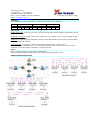
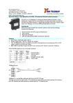
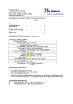
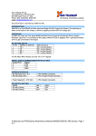
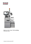
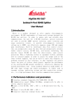
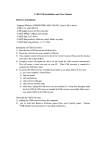
San Telequip (P) Ltd.,
4 Crystal House , 235, Navi Peth
Off LBS Road, Pune 411 030, India
Phone : 91-20- 24320023, 24334423, 65001587
email : [email protected]
Connecting. Converting. Leading !
Document Name : User Manual for Self Healing Serial to Fiber Converter Model SC12 FS SH
The SC12FS SH is used to transmit the RS232 / RS485 / RS422 signal by the fiber optic ring network at a high
rate, over long distances, offering immunity to various types of noise and increasing the dependability of data.
The communications system model of SC12FS SH is one Master to multiple Slaves.
It is easy to structure a network of Star, Chain and Loop type.
It is a Self Healing product. When any of Slave nodes fails or the Power is cut off or there is a break in fiber etc,
the communication shifts to the alternate loop & resumes normal communication, through the normal loop, once
the fault is restored.
Specifications :
Ports
Code error rate
Wavelength
Cable
Fiber Connectors
Distance
Sensitivity
Code
Serial Port Connector
Baud Rate
: below 10-9
: SM : 1310 nm, MM : 850 nm
: SM : 09/125 µm
: MM : 62.5/125 µm or 50/125 µm
: ST, SC or FC. Select any one.
: SM : 20km, MM : 5km
: -35 dbm
: HDB3
: 10 pin Screw type Industrial Connectors for RS-232, RS-422 and RS-485
: 300bps to 115.2Kbps
Power
Power supply
Power
: DC 9 - 30V DC. Optional, external AC 230V AC Adapter for 12V DC.
: <2W
Mechanicals
Dimensions
Weight
: 100mm × 90mm ×3 0mm
: 0.7kg
Operating Conditions
Working temperature
Storage temperature
Relative humidity
: -20 to +70 °C.
: -40 to +85 °C.
: 95% rh non condensation
Protection
MTBF
ESD Protection
Isolation Protection
Surge Protection
: Better than 100 thousand hours
: 15 KV ESD Surge Protection for all signals (Optional)
: 2.5KV Optical Isolation for Power and Signals (Optional)
: 600W on RS485 lines
Indicators
MAIN
SUB
LOOPA
LOOPB
TxA
RxA
TxB
RxB
TXD
RXD
: Master station, Red
: Slave station, Green
: Fiber port A receiving, Green
: Fiber port B receiving, Green
: A Data Send, Green
: A Data Receive, Green
: B Data Send, Green
: B Data Receive, Green
: Serial port Data Send, Green
: Serial port Data Receive, Green
DIP Switches
DIP switch 1 is used for the configuration of the Master and Slave. Up ( ON ) is Master & Down ( OFF ) is Slave.
Switch 2 is used to add a 120 Ohm matching resistor on RS-485 data lines.
Up is with the terminations & Down is without terminators.
The switch 3 and 4 is not used.
.
San Telequip (P) Ltd.,
4 Crystal House , 235, Navi Peth
Off LBS Road, Pune 411 030, India
Phone : 91-20- 24320023, 24334423, 65001587
email : [email protected]
Connecting. Converting. Leading !
.
Pin Details :
A 10 pin Industrial grade Terminal Strip is used to connect with the device data port.
Signal
Pin
T+
1
RS485/RS422
TR+
R2
3
4
Gnd
5
RS232
TX
RX
6
7
Gnd
8
Power
V+
9
V10
Connections :
RS232 connections : Connect the TX of the converter to the RX of the external equipment and the RX to the TX,
the GND to the GND.
RS-485/422 connection : RS485 / 422 is auto selectable. Pin 1 (T+) and Pin 2 (T-) are used for RS485, and pin
1,2,3,4 are used for RS422.
Important : It is necessary to add a matching resistance of 120 Ohm both at the start & at the end of the RS485
loop. (By turning on the switch 2)
Fiber connection : To construct a self-heal loop, the fiber network must be constructed as A
to B and B to A,TX to RX and RX to TX. In a self-heal loop network of 2 fibers there can be only one master
station but several slave stations. Following is a sample connection.
Power :
DC9 - 30V power supply needed, the power is low than 2W.
Notice of the power polarity, the apparatus will be damaged when the polarity is reverse.
CONNECTION ARCHITECTURES