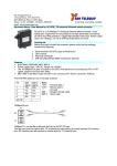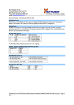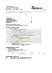
1
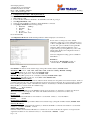
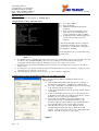
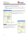
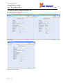
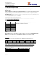
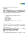
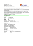
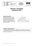
San Telequip (P) Ltd.,
4 Crystal House, 235, Navi Peth
Off LBS Road, Pune 411 030
Phone : 020- 24320023, 65001587
email : [email protected]
Connecting. Converting. Leading !
..
Document Name : User Manual for SC10EJ Serial to Ethernet Converter
INDEX
1.
2.
3.
4.
5.
6.
7.
8.
9.
Technical Specifications
Modes of Operation
Configuring the SC10 EJ : Through Serial Port
a. Configuring the SC10 EJ : Through Telnet.
b. Configuring the SC10 EJ : Through Ethernet side Utility.
c. Configuring the SC10 EJ : Through HTTP
Operation in Normal Mode
Communication Ports Details of SC10 EJ
DIP Settings & LED Status Indicators
Cable Details
Back to Back Scheme
Configuration for Virtual Com Port
1
1
2
3
3
5
6
6
6
7
7
8
SC10 EJ is Serial to Ethernet PCB Module. It is an Interface Converter between Ethernet and RS232 / RS485 2 / 4
Wire devices. The Serial & Ethernet Ports along with the LED indications are on the front facia, the Power Supply
jack is on the Right-Back side & the DIP switches on the Right-Front side.
1.
TECHNICAL SPECIFICATIONS
Communication Interfaces
Ethernet Interface
Serial Interface
Baud Rates
Network Protocols
Configuration
Indications
Modes
Mechanical : Connectors
RS232 / RS485 / 422
Ethernet
Dimensions
Power Supply
Power Supply
Environmental
Operating Temperature
Relative Humidity
10 / 100 Base Mbps
RS-232 or RS485 2/4 Wire.
1200 to 115 Kbps.
TCP, IP, ICMP, ARP, Telnet, UDP, HTTP.
Serial port, Ethernet Port, Utility on a PC, HTTP.
4 Status LED’s for Serial & Ethernet activities.
Both Master / Slave Modes are possible.
9 Pin Howder Connector.
RJ45.
EJ : 126 mm x 80 mm x 40 mm (L x W x H).
230V AC. Range 90 to 270V AC.
0°C to 55°C.
10 to 90 % RH non-condensing.
Table - 1
2. MODES OF OPERATION
The SC10 EJ Converter operates in the following modes: Configuration Mode :
Through Serial Mode
: By any Terminal Software or our PC Side Utility.
Through Ethernet Mode
: Our PC Side Utility.
Through Telnet
This mode is used to configure the SC10 EJ’s functional parameters / settings via the Serial port. If at “Power On”,
DIP 1 & 3 are ON, you can enter the Configuration mode.
NOTE : DIP1 is to be turned ON only if the configuration is being done through RS232 port.
Turn DIP 1 OFF after configuration through Serial Port & Reset the Converter.
Normal Mode :
If at Power ON, DIP 1 is OFF then SC10 EJ will go in Normal operating mode. In TCP Slave mode, it will directly go
in Disconnect State, waiting for connection, while in case of TCP Master Mode, it will try to establish connection with
remote device.
In the Normal mode, SC10 EJ performs the data conversion from Ethernet to Serial and vice a versa.
Page 1 of 10
San Telequip (P) Ltd.,
4 Crystal House, 235, Navi Peth
Off LBS Road, Pune 411 030
Phone : 020- 24320023, 65001587
email : [email protected]
Connecting. Converting. Leading !
..
3. Configuration Procedure : Through Serial Port :
Configuration Procedure : Through Serial Port :
1. Make DIP 1 & 3 ON.
2. Connect Tx, Rx and Gnd of SC10 EJ to the COM Port of the PC as per fig. 5.
3. Start HyperTerminal on PC.
4. Select the same COM Port of the PC to which SC10 EJ is connected.
5. Setup Hyper Terminal with following settings:
a. Baud Rate : 9600 bps
b. Data Bits
: 8
c. Parity
: None
d. Stop bits
:1
e. Flow Control : None
Power On SC10 EJ .
A Configuration Menu with all the default parameters will be displayed as shown below :
If user wishes to change any of the default
parameters, simply type corresponding letter (viz. b
or B for setting IP Address etc.), then list of current
set value and options available for that particular
parameter will be displayed. Enter the option
required and upon pressing Enter key, same value
will be again displayed in configuration menu as
default parameter.
Various Configuration setting options available in
SC10 EJ are : IP Address
It should be in “Dot-Decimal” format, i.e.
“192.168.106.11”. : Default: 127.0.0.1
Figure 1
Port Number : It must be in 0 to 65534 range. ( Except Port number 65535 ). Default : 1001
Baud Rate : Select from : 1200, 2400, 4800, 9600, 19200, 38400 and 57600bps. Default : 9600bps
Parity : Select Parity from : None, Even, Odd. Default: None
Stop Bits : Select Stop bits from : 1 bit, 2 bits. Default: 1 bit
Data Bits : Select Bits per byte from : 7 bits/byte, 8 bits/byte. Default: 8 bits / byte
Flow Control : Select Flow control as : None, RTS / CTS. Default: None
Maximum Intercharacter Delay
SC10 EJ packets the Serial data & sends it to Ethernet. If the characters in the packet are less than 255 bytes, the above
parameter will come into play. After last character has been received from serial side, the converter waits for this time
before sending the packet. Value of 0 disables this function. Actual delay is calculated as Maximum Intercharacter
Delay X 10ms, i.e. it can be in the 10 - 2550ms range.
Default:
10 (i.e. 10 msec)
Connection Timeout
Specifies timeout (in minutes) for the TCP/ IP connections in case there is no transaction of data in any direction.
Timeout should be in the range 0 to 255. Value of 0 disables this function (connection never times out).
Default:
5 (5 minutes)
Destination IP
Defines the Destination IP Address. It should be in “dot-decimal” format, i.e. “198.168.106.14”.
Default:
0.0.0.0
Destination Port Number
Defines the destination data port number. Between 0 to 65535 range. ( Except Port number 65535 ) Default: 1001
Gateway IP address
Defines the IP address of the Network’s Gateway to which the SC10 EJ is connected. It should be in “dot-decimal”
format, i.e. “128.0.0.1”. Default: 0.0.0.0
SubNet Mask Address
It defines whether the Destination IP address is considered to be on the local network segment or foreign network
segment. It should be in “dot-decimal” format, i.e. “255.255.255.0”. Default: 0.0.0.0
Page 2 of 10
San Telequip (P) Ltd.,
4 Crystal House, 235, Navi Peth
Off LBS Road, Pune 411 030
Phone : 020- 24320023, 65001587
email : [email protected]
Connecting. Converting. Leading !
..
Operation Mode
Selects “Slave or Master Routing Mode”. Default: Slave.
Configuration Procedure : Through Telnet:
1) Go to Start Run.
2) Type Command
3) MSDOS Command Prompt will be
displayed.
4) Type C:\telnet 192.168.106.11 (Type
previously set Source IP address for
present configuration) and press Enter.
5) Configuration menu will be displayed as
shown in the screenshot in below
diagram.
After the Configuration menu is displayed,
configuration should be done in the same
way as is done for Serial Port configuration
through Hyper Terminal.
Following features are provided while using
Telnet menu :
Figure – 2
1) If communication is established and data transfer is in progress and Telnet menu is invoked, then the user will
be asked to enter valid PASSWORD. Once user enters valid password, Data transfer will stop and
Configuration menu will be displayed. Default password is “ net ” and is case sensitive.
2) If Telnet menu is invoked and valid Password is not entered for one minute, then connection to host ID i.e.
Device is lost.
3) If valid password is entered and menu is displayed but afterwards no action is performed to change any of the
parameters then connection to device is lost.
4) After changing the parameters, when we press ‘p or ‘P’ to end the configuration.
Configuration Procedure through Ethernet Mode (PC side utility provided):
When configuring the SC10 EJ through PC side utility use the
following steps:
1) Start SC10 EJ Config utility (Through shortcut on desktop or
through Start -> Programs -> SC10Config -> SC10Config)
2) Go to step 3 if IP address of SC10 EJ converter is not according
to the required local network settings.
3) Search for the SC10 EJ Converter by pressing “Search “ Button
on the utility.
4) If only one SC10 EJ converter is present on the network, then
an IP address setting dialog box will appear in this box. Set the
IP address as pre your network configuration.
5) If more than one SC10 EJ converter are attached to the
network, then a list box containing MAC address of the
converters will appear. From this list, select any MAC address
and set the IP address for the corresponding converter.
6) After IP address has been set, select “Ethernet” under
“Programming SC10 through” Option. Enter the “Set IP
Address” in Drop Down list given in front of “Enter/Select IP
Address of SC10.” Now press “Login” again.
Figure 3
Page 3 of 10
San Telequip (P) Ltd.,
4 Crystal House, 235, Navi Peth
Off LBS Road, Pune 411 030
Phone : 020- 24320023, 65001587
email : [email protected]
Connecting. Converting. Leading !
..
Note:
a) Make sure that the IP of the converter and PC are within the same range. I.e. if the IP address of the converter
is 192.168.106.xxx then the IP address of the PC must be 192.168.106.yyy.
b) To make sure the converter is reachable, you can Ping the converter.
c) The IP address of the PC can be configured from Control Panel Network -> Protocol -> TCP/IP
(Properties).
d) If the connection is established, the appropriate version and a message will be displayed at the bottom of the
window. When the desired settings are done, converter should be returned to “Normal Mode” by pressing
“Save & Exit ” button on the utility.
Network Settings
To set any parameter of network settings, select the parameter from the
drop down list.The utility will fetch the current value from the converter
and display on screen. The new value then can be entered and sent to
converter by pressing “Write” Button (Figure 4).
All the network settings can be done exactly as per already specified
configuration steps for a) Configuration through Serial and b)
configuration through Telnet
Figure 4
Serial Settings
To set any parameter of serial settings, select the parameter from the Drop
Down List. The utility will fetch the current value from the converter and
display on screen. The new value then can be entered and send to the
converter by pressing “Write” Button.(Figure 5)
All the serial settings can be done exactly as per already specified
configuration steps for a) Configuration through Serial and b)
configuration through Telnet
Figure - 5
Page 4 of 10
San Telequip (P) Ltd.,
4 Crystal House, 235, Navi Peth
Off LBS Road, Pune 411 030
Phone : 020- 24320023, 65001587
email : [email protected]
Connecting. Converting. Leading !
..
CONFIGURATION THROUGH HTTP (IE ) : Open Internet Browser using the IP of the device.
Proceed as per the screens below.
Default Page
Network Parameter Setting
Page 5 of 10
Serial Parameter Setting
San Telequip (P) Ltd.,
4 Crystal House, 235, Navi Peth
Off LBS Road, Pune 411 030
Phone : 020- 24320023, 65001587
email : [email protected]
Connecting. Converting. Leading !
..
4. OPERATION IN NORMAL MODE
Ensure that you have configured the SC10 EJ before entering this mode. If at Power On, DIP 1 is OFF, then SC10 EJ
will go in Normal operating mode. In the Normal Mode there are two sub modes of operation : TCP Slave Mode
In Slave Routing Mode, SC10 EJ is always in Listen State (Waiting for a connection). The connection command
must be from peer side. In the Slave Mode, SC10 EJ will work with any station on the network that contacts it,
irrespective of settings of Destination IP and Destination Port number in SC10 EJ’s Configuration parameters.
TCP Master Mode
In the Master Routing Mode, SC10 EJ always initiates a connection with remote device whose IP Address & Port
no’s is set as destination IP & port no’s for SC10 EJ.
Serial to Ethernet Data transfer using RTS / CTS.
If Flow control is enabled, additionally RTS and CTS lines are used, apart from Tx, Rx and GND.
5. COMMUNICATION PORTS DETAILS
Serial Port Details :
Port Pin
Assignments
Pin 1
Pin 2
Pin 3
Pin 4
Pin 5
Pin 6
Pin 7
Pin 8
Pin 9
Pin
Configuration
TX
RX
GND
RTS
CTS
TX+
TXRX+
RX-
RS-232 / RS485-2 / 4 Wire options are available as default for Serial
Communication through a 9 Pin Howder connector.
Pin Details of Serial Port is as alongside.
Table – 2
Ethernet Port
The SC10 EJ Converter has a RJ-45 Ethernet port. The SC10 EJ is connected using the Straight Ethernet Cable
when connected via a Hub / Switch or a Cross-Ethernet Cable when connected directly to the PC.
6.
DIP & LED’s Status Indications
DIP Details
Set DIP Switches as given below depending upon the communication standard required by you.
ON
OFF
DIP 1
Config Mode
Normal Mode
DIP2
RS485 2 Wire
NA
DIP3
RS232
NA
DIP4
RS485 4 Wire
NA
Auto Negotiation
Force 100 Mbps
Force 10 Mbps
DIP 5
OFF
ON
ON
DIP 6
OFF
OFF
ON
Table – 3
NOTE : DIP1 is to be turned ON only if the configuration is being done through RS232 port.
NOTE : Turn DIP 1 OFF after configuration through Serial Port & Reset the Converter.
LED Indicators : Operation
LED No. Indication
Status
LED 2A
Link
Active when Link is established
LED 2B
Active when collisions occur.
Collision
LED 4A
Reception on Serial side
Active when Data received.
LED 4B
Transmission on Serial side Active when Data is transmitted.
Table - 4
Page 6 of 10
San Telequip (P) Ltd.,
4 Crystal House, 235, Navi Peth
Off LBS Road, Pune 411 030
Phone : 020- 24320023, 65001587
email : [email protected]
7.
Connecting. Converting. Leading !
..
Cable Details :
Cable Details : RS232 Side of SC10 EJ to any other Serial Port.
TX
RX
RX
TX
RTS
RTS
CTS
CTS
GND
GND
SC10 EJ Side
PC / COM Port
Figure - 6
Cable Details : RS485 : 4 Wire
Signal
Direction
TX+
Output of SC10 EJ
TXOutput of SC10 EJ
RX+
Input to SC10 EJ
RXInput to SC10 EJ
Table 5
Cable Details : RS485 – 2 Wire
Signal
Direction
TX+
Bi-Directional Signal
TXBi-Directional Signal
Table 6
8.
Will Connect To
RX+ of your Device
RX- of your Device
TX+ of your Device
TX- of your Device
Will Connect To
TX+ of your Device
TX- of your Device
Back to Back (1:1) scheme
For back to back communication between two SC10EJ make the Connection as follow –
Serial Master
device
H
U
B
Serial to Ethernet
SC10EJ 1 (Master)
Serial to Ethernet
SC10EJ 2 (Salve)
Serial link
RJ 45
RJ 45
Serial Slave
device
Serial link
Procedure
1. Configure 1 Ethernet Converter as a Master & the other Ethernet Converter as Slave.
2. Connect the Master converter to the Serial Master device ( A device which is requesting for data from slave
device). If application software is your Master device then the Ethernet Master converter will connect to that
PC’s com port.
3. Connect the Slave converter to your serial device, which is responding to requests from the Master Serial
Device.
For Configuration of Master and Slave in SC10EJ follow step as below √ Set one SC10 EJ as a Master mode and another SC10EJ as a Slave mode, through option available with config
utility i.e. “Operation Mode”.
√ Configure the destination IP of the Master Converter as same as the source IP address of the Slave converter.
√ Configure the destination Port number of the Master Converter as same as the source Port number of the Slave
converter.
√ Ensure Serial parameters of Master and Slave are identical.
√ Before going for required application setup, check basic communication test by telnet and HyperTerminal.
NOTE : Consult Us for 1 to Many Back to Back Scheme.
Page 7 of 10
San Telequip (P) Ltd.,
4 Crystal House, 235, Navi Peth
Off LBS Road, Pune 411 030
Phone : 020- 24320023, 65001587
email : [email protected]
Connecting. Converting. Leading !
..
CONFIGURATION FOR VIRTUAL SERIAL PORT CONSOLE :VER 2.7.0
Unzip from SC10EJConfig\Virtual Com\Vserport.zip in the enclosed CD.
Double click on required exe File .
Follow the below screens to install the Virtual Com Port.
Right Click inside the above screen to get “Add the Port Option “
Add Port
The following screens below will appear.
Select “ Continue Anyway”.
Selected COM Port will be Added. Port no’s 8 in the picture is only for reference.
Page 8 of 10
San Telequip (P) Ltd.,
4 Crystal House, 235, Navi Peth
Off LBS Road, Pune 411 030
Phone : 020- 24320023, 65001587
email : [email protected]
Connecting. Converting. Leading !
..
Right Click on the added COM port & choose Add Net option. The snap shots are below
In the next screen you are required to insert Network details
Page 9 of 10
San Telequip (P) Ltd.,
4 Crystal House, 235, Navi Peth
Off LBS Road, Pune 411 030
Phone : 020- 24320023, 65001587
email : [email protected]
Connecting. Converting. Leading !
..
Following screens are the confirmation of the IP selected & communication established
Congratulations!!! The Virtual Com Port is installed
Page 10 of 10