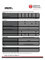
1
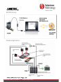
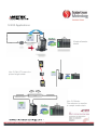
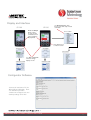
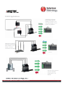
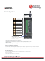
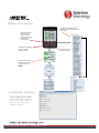
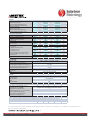
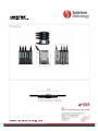
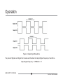
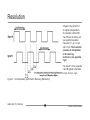
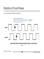
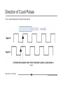
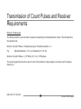
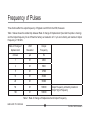
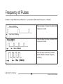
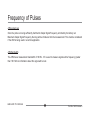
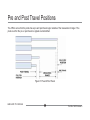
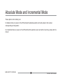
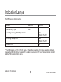
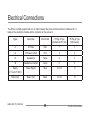
MODIM MODBUS INTERFACE MODULE A PLC Interface Module for Orbit®3 Description Solartron Metrology, the world leader in measurement innovation, introduces a MODBUS Interface Module (MODIM) which provides an easy to use gateway between MODBUS PLCs and Solartron Metrology's Orbit®3 Digital Measurement System which is a flexible and highly accurate measuring system. The Orbit®3 system can also interface to any sensor with an analogue output as well as the myriad of linear measurement sensors manufactured by Solartron Metrology. This means that the system can be used for temperature, pressure, force, rotary measurement and linear displacement, providing all these process variables to a PLC through one simple MODBUS communications interface. Features MODBUS RTU up to 115200 baud Access complex sensor networks with varying interfaces through a set of MODBUS parameters in a single device Connects to all Solartron Gauging Probes, Displacement, Orbit® LT, and Orbit® LTH. Simple network set up via a PC application. EDCR number: 20860 Issue number: 1 Datasheet number: 503178 1 MODIM Setup Orbit3 Gateway Interface Sample Application EDCR number: 20860 Issue number: 1 Datasheet number: 503178 2 MODIM Electronics Interface Network Protocol Hardware Serial Interface Data Transfer MODBUS RTU SLAVE RS485 Individual Readings of Network Module Data Synchronised readings of Network Module data Baud Rates Maximum Network Size (Note 1) Up to 115,200 Up to 150 modules ORBIT Network Orbit Modules Orbit Measurement (Note 3) Linear Displacement Sensors range 0.25mm to 300mm. Analogue Input Modules 0-10V, 420mA. Rotary Encoder Modules and Non Contact Laser Modules Standard Mode Environmental Sealing Storage Temperature (ºC) Operating Temperature (ºC) EMC Emissions EMC Immunity Power (Note 2) IP43 -20 to +70 5 to 60 EN61000-6-3 and EN61326 EN61000-6-2 and EN61326 5±0.25 VDC @ 0.06A typical Material Body ABS and Nylon Note1 : The Network size refers to the Orbit Network to which the MODIM provides a gateway Note2: The power is for the MODIM only, the Orbit Network will require additional power depending on the modules that make up the network (Typically each Orbit module will require 60mA @ 5V DC nominal) Refer to User Manual for Details Note3: The Orbit Network can be set to operate in various measurement modes however the MODIM only allows configuration of Orbit Standard mode to facilitate the two MODIM Data Transfer methods EDCR number: 20860 Issue number: 1 Datasheet number: 503178 3 SI 100 & SI 200 Single and Dual Channel systems for easy connections into PLC or Automation Description Solartron Metrology, the world leader in linear measurement innovation, introduces two new Orbit®3 based systems for easy, low cost connections into PLCs and process control systems. The SI 100 is a single channel, stand alone system, while the SI 200 also connects to an Orbit®3 probe for a two channel reading. Features Integral Readout with colour LCD Display and keypad. Set tolerance and process limits via keypad Detachable probe plug on housing for easy installation. (Gauging probes, Block Gauges & Flexures only) Replace probe with no calibration or reprogramming Modbus output (RTU or ASCII) over RS485 or RS232 Programmable discrete I/O (4 inputs, 3 outputs) Multiple formulas available for SI 200 (A+B, A-B, etc.) Available with all Solartron Gauging probes, Displacement sensors, Orbit LT, and LTH. SI 200 can stack laser with gauging probe or displacement sensor. 24V DC Power Supply EDCR number: 20766 Issue number: 3 Datasheet number: 503083 1 SI 100 Applications Simple height check measurement to PLC via MODBUS Chip height check with Orbit LT. Measurement sent to PLC on print command via RS232 EDCR number: 20766 Issue number: 3 Datasheet number: 503083 2 SI 200 Applications Simple diameter check Use 2 Orbit LT Lasers for piston height check Use 2 S-Series Transducers to monitor a sample under strain EDCR number: 20766 Issue number: 3 Datasheet number: 503083 3 Pin Configuration 12 Input 4 11 Input 3 10 Input 2 9 Input 1 8 Output Supply In 7 Output 3 6 Output 2 5 Output 1 4 Modbus B (RS485 or RS232) 3 Modbus A (RS485 or RS232) 2 0V Power in Return 1 18-32 V DC Power In Mini-USB Port for configuration via a PC and firmware updates • Input pins can be set Active Hi or Active Lo • Output pins can be Active Hi or Active Lo and set to NPN, PNP or Logic • DIN Rail mount • Input pins are programmable (typical functions: Zero, Print, Preset) Serial Output Options The SI 100 and SI 200 have a standard Modbus interface (RTU or ASCII). However, pins 3 & 4 can also be configured as an ASCII Serial Interface mode, allowing the user to select from several different protocols, including compatibility with Solartron’s SI 1500, SI 3500 and C55. Accessories +24V Power Block with Mains Leads. Available with UK, EU, and US plugs Spare T-con Mounts USB to Mini-USB cable for PC connection EDCR number: 20766 Issue number: 3 Datasheet number: 503083 4 Display and Interface SI 100 SI 200 Use Action Screen to Zero, Preset, Print, and setup shortcut commands ŻLeft and ŹRight Arrows can be used as shortcut commands to Zero or Preset while in Display Mode ACTION SCREEN Press ƔEnter to go to “Action” Screen Use ŸUp and źDown arrows to change g display screens Configurator Software Connect SI 100/200 to PC via Mini-USB to USB cable. Then use Solartron provided software to configure unit, and backup settings to PC file! EDCR number: 20766 Issue number: 3 Datasheet number: 503083 5 Orbit ACS Digital Gauging Probes (with connector between probe and electronivs module) Product Spring Push Axial Cable SIxxxP/1/S SIxxxP/2/S SIxxxP/5/S SIxxxP/10/S SIxxxP/20/S SIxxx6P/2/S Spring Push Radial Cable SIxxxPR/1/S SIxxxPR/2/S SIxxxPR/5/S SIxxxPR/10/SSIxxxPR/20/S N/A Pneumatic Axial Cable N/A SIxxxP/2/P SIxxxP/5/P SIxxxP/10/P SIxxxP/20/P N/A Pneumatic Radial Cable N/A SIxxxPR/2/P SIxxxPR/5/P SIxxxPR/10/P SIxxxPR/20/P N/A Measuring Range (mm) 1 2 5 10 20 2 Body Diameter 6h6 8h6 Note SIxxx can be either SI100 or SI200 Performance Accuracy (% of Reading)1 Repeatability μm2 Resolution μm -user selectable Alarm Outputs - selectable High, OK, Low Discrete Inputs - user selectable Update Rate for I/O discretes (ms) Bandwidth of Electronics (Hz) - user selectable Communications Interface Protocol Communications Interface Hardware Update Rate ate for o Se Serial a Data ata ((ms) s) Pre Travel (mm) Post Tavel (mm) Tip Force (N) at Middle of Range ±20% Spring Push Pneumatic at 0.4 bar Pneumatic at 1 bar 0.2 0.15 0.15 <0.1 <0.01 <0.01 <0.05 3 outputs either NPN, PNP, logic Programable Active Hi or Lo eg. Print, Zero, Preset (see manual for other options) 5 460, 230, 115, 58, 29, 14, 7,4 MODBUS (RTU or ASCII) or Solartron Serial Formats RS485 or RS232 (User selectable) Up to 115,200 Baud 5 25 0.15 0.85 0.35 0.35 Environmental Sealing for Probe Sealing for Probe Interface Electronics Storage Temperature (ºC) Probe Operating Temperature with Gaiter (ºC) Probe Operating Temperature without Gaiter (ºC) Electronics Operating Temperature (ºC) EMC Power 0.2 0.7 N/A N/A 0.8 0.85 2.8 0.7 2.5 N/A N/A IP65 with gaiter or IP50 without gaiter Top and Front: IP41, Rear: IP20, In line connector: IP67 -20 to +70 +5 to +80 -10 to +80 0 to 60 Emissions EN61000-6-3, EN61326 Immunity EN61000-6-2, EN61326 18 to 32 VDC @ 0.07A typical Material Probe Body Probe Tip (options) Gaiter (standard) Cable Electronics Module Stainless Steel Nylon, Ruby, Silicon Nitride, Tugsten Carbide Fluoroelastomer PUR ABS [1] Accuracy 0.1ȝm or % reading, whichever greater [2] Obtained by repeated operation against a carbide target with side load applied to bearing EDCR number: 20766 Issue number: 3 Datasheet number: 503083 6 Instrumentation Functionality Measurement Measurement Modes - SI100 Measurement Modes - SI200 Measurement Types Measurement Modes Measurement Units A, MAX-MIN A,B, A+B, A-B, (A+B)/2, (A-B)/2, MAXA-MINA, MAXB-MINB Track, Peak+, PeakAbsolute, Zero (tare), Preset mm, inches or mils Display Analogue Digital Warnings Bar representing reading Digital up to 5 decimal places mm (6 for inches) Red bar and red digital reading indicates measurment outside of limits Keypad Type Sealed Membrane The SI 100 and SI 200 can also be ordered connected directly to the digital gauging probe for higher accuracy. The SI100 and SI200 can also be ordered with the connector between the digital gauging probe and the Electronics Module placed in line along the cable. Performance specifications will vary if the SI100 or SI200 is supplied connected to other transducers or laser products – see the Solartron website or contact your local sales office/distributor for further information. EDCR number: 20766 Issue number: 3 Datasheet number: 503083 7 Drawing EDCR number: 20766 Issue number: 3 Datasheet number: 503083 8 SI400 A Four Channel system for easy connections into PLC or Automation Description Solartron Metrology, the world leader in linear measurement innovation, introduces a new Orbit®3 based system for easy, easy low cost connections into PLCs and process control systems. The SI400 will connect to, and power, three additional sensors for a four channel reading. You can even combine gauging probes, Orbit® LT, and Orbit® LTH on the same stack of modules. No other digital system offers this! Features Integral Readout with colour LCD C Display and keypad. Set tolerance and process limits via keypad Detachable probe plug on housing for easy installation. (Gauging probes, Block Gauges & Flexures only) Replace probe with no calibration or reprogramming Modbus output (RTU or ASCII) over RS485 or RS232 Programmable discrete I/O (4 inputs, 3 outputs) Track, Peak, and Max-Min Modes for each channel 24 VDC Power Supply Works with Gauging Probes (all types), Displacement, Orbit® LT, and Orbit® LTH. EDCR number: 20908 Issue number: 1 Datasheet number: 503174 1 SI 400 Applications Checking a jet engine turbine blade with two Orbit® LTH Lasers, and Two Ultra Feather Touch probes over Modbus Check four corners of cell phone glass with Ultra Feather Touch Probes, via Print command over RS232 Use four mini-probes to check h k a di diameter. t Output to PLC via RS232. EDCR number: 20908 Issue number: 1 Datasheet number: 503174 2 Pin Configuration 12 Input 4 11 Input 3 10 Input 2 9 Input 1 8 Output Supply In 7 Output 3 6 Output 2 5 Output 1 4 Modbus B (RS485 or RS232) 3 Modbus A (RS485 or RS232) 2 0V Power in Return 1 18-32 V DC Power In Mini-USB Port for configuration fi ti via i a PC and d firmware updates • Input pins can be set Active Hi or Active Lo • Output pins can be Active Hi or Active Lo and set to NPN, PNP or Logic • DIN Rail mount • Input pins are programmable (typical functions: Zero, Print, Preset) Serial Output Options The SI400 has a standard Modbus interface (RTU or ASCII). However, pins 3 & 4 can be configured as an ASCII serial interface. (Pin 3: RS232TX, Pin 4: RS232 RX). In this mode, the user can select from several different ASCII protocols, including compatibility with Solartron’s SI1500, SI3500 and C55. Accessories +24 V Power Block with Mains Leads. Available with UK, EU, and US plugs Spare T-con Mounts USB to Mini-USB cable for PC connection EDCR number: 20908 Issue number: 1 Datasheet number: 503174 3 Display and Interface Use Action Screen to Zero, Preset, Print, and setup shortcut commands ŻLeft and ŹRight Arrows can be used d as shortcut h t t commands to Zero or Preset while in Display Mode Use ŸUp and źDown arrows to change display screens ACTION SCREEN Press ƔEnter to go t “Action” to “A ti ” Screen S You can also display just two channels at a time (A and B, or C and D) Configurator Software Connect SI400 to PC via Mini MiniUSB to USB cable. Then use Solartron provided software to configure unit, and backup settings to PC file! EDCR number: 20908 Issue number: 1 Datasheet number: 503174 4 Products Spring Push Axial Cable Spring Push Radial Cable Spring Push Axial Cable Feather Touch Spring Push Radial Cable Feather Touch Pneumatic Axial Cable Pneumatic Radial Cable Pneumatic Axial Cable Feather Touch Pneumatic Radial Cable Feather Touch Measurement Performance Measurement Range Accuracy (% of Reading) (Note 1) Repeatability (worst case) μm (Note 2) Repeatability (typical) μm (Note 3) Resolution (μm) Pre Travel (mm) Post Travel (mm) Tip Force (N) at Middle of Range ±20% Spring Push Spring Push Feather Touch Pneumatic at 0.4 bar Pneumatic at 1 bar Pneumatic Feather Touch ±30% at 0.3 bar Pneumatic Feather Touch ±30% at 1 bar Pneumatic Jet Temperature Coefficient %FS/ºC Environmental Sealing for Probe Sealing for Probe Interface Electronics Storage Temperature (ºC) Probe Operating Temperature with Gaiter (ºC) Probe Operating Temperature without Gaiter (ºC) Electronics Operating Temperature (ºC) EMC Emissions EMC Immunity Power Material Probe Body Probe Tip (options) Gaiter (standard) Cable Electronics Module Electronics Interface (Orbit ACS) Alarm Outputs - selectable High, OK, Low Di Discrete t IInputs t - user selectable l t bl Update Rate for I/O discretes (ms) Bandwidth of Electronics (Hz) - user selectable Communications Interface Protocol Communications Interface Hardware Update Rate for Serial Data (ms) SI400P/1/S SI400P/2/S SI400P/5/S SI400P/10/S SI400P/20/S SI400P10/2S SI400PR/2/S SI400PR/5/S SI400PR/10/S SI400PR/20/S SI400PR10/2/S SI400T/2/S SI400T/5/S SI400T/10/S SI400T/20/S SI400T10/2S SI400TR/2/S SI400TR/5/S SI400TR/10/S SI400TR/20/S SI400TR10/2S SI400P/2/P SI400P/5/P SI400P/10/P SI400P/20/P SI400P10/2S SI400PR/2/P SI400PR/5/P SI400PR/10/P SI400PR/20/P SI400PR10/2/P SI400T/2/P SI400T/5/P SI400T/10/P SI400T/20/P SI400T10/2S SI400TR/2/P SI400TR/5/P SI400TR/10/P SI400TR/20/P SI400TR10/2S 1 0.2 0.15 0.05 0.01 0.15 0.35 2 0.2 0.15 0.05 0.01 0.15 0.85 5 0.15 0.15 0.05 0.05 0.15 0.85 10 0.15 0.15 0.07 0.05 0.15 0.85 20 0.15 0.15 0.07 0.1 0.15 0.85 2 0.2 0.15 0.05 0.01 0.15 8.85 0.7 0.3 N/A N/A N/A N/A N/A 0.01 0.7 0.3 0.7 2.6 0.18 1.1 0.85 0.01 0.7 0.3 0.7 2.6 0.18 1.1 0.85 0.01 0.7 0.3 0.7 2.6 0.18 1.1 0.85 0.01 0.7 0.3 0.7 2.6 0.18 1.1 0.85 0.01 0.7 0.3 0.7 2.6 0.18 1.1 0.85 0.01 IP65 with gaiter or IP50 without gaiter Top and Front: IP41, Rear: IP20, In line connector: IP67 -20 to +70 +5 to +80 -10 to +80 0 to 60 EN61000-6-3 and EN61326 EN61000-6-2 and EN61326 18 to 32 VDC @ 0.07A typical Stainless Steel Nylon, Ruby, Silicon Nitride, Tugsten Carbide Fluoroelastomer PUR ABS 3 outputs either NPN, PNP, logic Programable Active Hi or Lo 4 iinputs t user configurable fi bl eg. P Print, i t Z Zero, P Presett 5 460, 230, 115, 58, 29, 14, 7,4 MODBUS (RTU or ASCII) or Solartron Serial Formats RS485 or RS232 (User selectable) Up to 115,200 Baud 25 Note 1: Accuracy 0.1 μm or % reading whichever greater Note 2: Obtained by repeated operation against a carbide target with side load applied to the bearing using max-min Note 3: Obtained by repeated operation against a carbide target standard deviation from average (68%) For specifications of other Gauging and Displacement Transducers, Orbit® LT, or Orbit® LTH, please refer to their respective datasheets. EDCR number: 20908 Issue number: 1 Datasheet number: 503174 5 Instrument Functionality Measurement Measurement SI400 Measurement Types Measurement Modes Measurement Units A, MAXA-MINA, B, MAXB-MINB, C, MAXC-MINC, D, MAXD-MIND, Track. Peak+, Peak Absolute, Zero (tare), Preset mm, inches, mils Display Analogue g SI400 Digital SI400 Four Bars representing p g reading g showing g limits Four Digital up to 5 decimal places mm (6 for inches) Keypad Type Sealed Membrane For Gauging probes, SI100 and SI200 can also be ordered with no plug for higher accuracy, or inline plug along cable - Specs are for standard, plugged, gauging probes only. Specs will vary with other sensors. If considering another sensor, contact your local Solartron representative for details. - Standard cable length is 2 meters. Special cable lengths can be ordered. EDCR number: 20908 Issue number: 1 Datasheet number: 503174 6 Drawing EDCR number: 20908 Issue number: 1 Datasheet number: 503174 7 ABSOLUTE TTL MODULE XVHUOHDÀHW Product Description Introduction The Solartron ATM transducer comprises a sensor and conditioning electronics which provides an RS422 level square wave output. Each output pulse represents a discrete incremental displacement. This type of square wave output, often called TTL can be read by many basic counter cards and instruments. The major difference between the ATM and conventional incremental sensors which provide outputs of this type is that the ATM is an absolute sensor and therefore cannot lose its position even if it is moved quickly. Incremental sensors will miss count if moved too quickly, which means they need a reference signal at a known position to re-datum. The ATM does not need this and does not provide a reference signal. ABSOLUTE TTL MODULE 2 Part No. 502724 issue 9 Safety WARNING statements identify conditions or practices that could result in personal injury or loss of life Warnings and Cautions Warning: do not operate in an explosive atmosphere. Warning: this equipment is not intended for safety critical applications. Warning : do not exceed the maximum ratings as VSHFL¿HGLQWKLVGRFXPHQW CAUTION statements identify conditions or practices that could result in damage to the equipment or other property This equipment operates below the SELV and is therefore outside the scope of the Low Voltage Directive Symbols in this manual Service and Repair Indicates cautionary or other information ABSOLUTE TTL MODULE No user serviceable parts. Return to supplier for repair 3 Part No. 502724 Issue 9 Operation Output Signals Provided The ATM provides four output signals in the form of square waves. These are Signals A and B. Signal B is phase shifted 90 degrees to Signal A. For each signal A and B the inverse signal is also transmitted. The Signal A and the inverse signal A is often called a Differential Signal A and the Signal B and the inverse signal B a Differential Signal B. Signal A is commonly referred to as the IN PHASE Signal and Signal B as the QUADRATURE Signal, where quadrature indicates a 90 degree phase shift with respect to the in phase signal. ABSOLUTE TTL MODULE 4 Part No. 502724 issue 9 Operation Figure 2: Output Signal Waveforms The period of Signal A and Signal B is the same and therefore the Output Signal Frequency of A and B is:Output Signal Frequency = 1/PERIOD = 1/T ABSOLUTE TTL MODULE 5 Part No. 502724 issue 9 Resolution In figure 2 the period T of the signal corresponds to the resolution of the ATM. The ATM can be factory set to a specified resolution. These are 0.1 μm, 0.2 μm and 0.5 μm. The resolution assumes x4 interpolation in the receiving electronics. (see opposite Fig 3). The period T of the separate A and B signals is therefore 0.4 μm, 0.8 μm, 2 μm. Figure 3: X4 Interpolation (performed in Receiving Electronics) ABSOLUTE TTL MODULE 6 Part No. 502724 issue 9 Direction of Count Pulses For an inward displacement Signal A leads Signal B, Fig 4a ABSOLUTE TTL MODULE 7 Part No. 502724 issue 9 Direction of Count Pulses For an outward displacement Signal B leads Signal A Fig 4b ABSOLUTE TTL MODULE 8 Part No. 502724 issue 9 Transmission of Count Pulses and Receiver Requirements Number of Pulses sent The ATM will send the exact number of pulses corresponding to the displacement moved. This will depend on the resolution set. Number of A and B Pulses = Displacement (μm) / Selected resolution x 4. E.g. Selected Resolution = 0.1 μm. Displacement =1.5 mm Number of A and B Pulses = (1.5*1000) / (0.1 X 4) = 3750 pulses. The receiving electronics must be able to count x4 the Number of pulse edges to correctly count the pulses. (See Fig 3). ABSOLUTE TTL MODULE 9 Part No. 502724 issue 9 Frequency of Pulses Three factors affect the output frequency of Signals A and B from the ATM, these are: Maximum Output Signal Frequency, which is factory set. The ATM will never transmit at a higher frequency than this setting. The ATM resolution. The speed at which the probe is moved. The output frequency of Signals A and B is calculated from the equation. Output frequency = ABSOLUTE TTL MODULE Rate of change of Displacement (mm/sec)*1000 ATM Resolution x 4 10 Part No. 502724 issue 9 Frequency of Pulses Three factors affect the output frequency of Signals A and B from the ATM, these are: Table 1 below shows the relationship between Rate of change of Displacement (how fast the probe is moving) and the Output frequency for an ATM with a factory set resolution of 0.1 μm and a factory set maximum Output Frequency of 100 kHz. Rate of Change of displacement ATM Resolution Output Frequency mm/sec μm Hz 1 0.1 2500 2 0.1 5000 5 0.1 12500 10 0.1 25000 20 0.1 50000 50 0.1 100000 100 0.1 100000 Output Frequency Limited by maximum Output Signal Frequency Table 1: Rate of Change of Displacement and Output Frequency ABSOLUTE TTL MODULE 11 Part No. 502724 issue 9 Frequency of Pulses Example: Output Waveforms. (ATM set to 0.1 μm resolution, Max Output Frequency = 100 kHz) Probe moving at 1 mm/sec, therefore 2500 A pulses per second. Probe moving at 2 mm/sec, therefore 5000 A pulses per second. Probe moving at 50 mm/sec, therefore limited to Maximum Output frequency (100 kHz) ABSOLUTE TTL MODULE 12 Part No. 502724 issue 9 Frequency of Pulses ATM system Lag Once the probe is moving sufficiently fast that its Output Signal Frequency is limited by the factory set Maximum Output Signal Frequency then lag will be introduced into the measurement. This must be considered if the ATM is being used in a control application. ATM Bandwidth The ATM has a measurement bandwidth of 100 Hz. If it is used to measure signals with a frequency greater than 100 Hz then information about this signal will be lost. ABSOLUTE TTL MODULE 13 Part No. 502724 issue 9 Receiver Electronics The receiver electronics must be able to handle signals up to 4 times the Maximum Output Signal frequency to ensure correct operation and not lose count. ATM Maximum Output Signal Frequency Minimum Frequency for Receiver kHz kHz 50 200 100 400 125 500 180 720 250 1000 360 1440 500 2000 Table 2: Receiver Electronics Input Frequency Requirements ABSOLUTE TTL MODULE 14 Part No. 502724 issue 9 Pre and Post Travel Positions The ATM is set so that the probe has a pre and post travel region outside of the measurement range. If the probe is within the pre or post travel no signals are transmitted. Figure 5: Pre and Post Travel ABSOLUTE TTL MODULE 15 Part No. 502724 issue 9 Absolute Mode and Incremental Mode These options can be factory set. In Absolute mode, on power on the ATM will read its absolute position and send pulses to the receiver corresponding to this position. In incremental mode, on power on the ATM will treat this position as zero and will not send any pulses until it is moved. ABSOLUTE TTL MODULE 16 Part No. 502724 issue 9 Indication Lamps The ATM has two indication lamps. Condition Blue LED Probe Moving (>10μm) Flash RED LED Low Voltage warning (ATM still operates) ** Flash 20% On 80% Off Low or High Voltage Error Flash 80% On 20% Off Hardware Error On ** The ATM requires a +5 V ± 0.25 VDC Supply. If the voltage is outside of this range a warning is indicated, however the ATM will continue to operate. If the voltage is worse than 0.5 V out of range an error is indicated and the ATM stops transmitting signals. ABSOLUTE TTL MODULE 17 Part No. 502724 issue 9 Technical Data Measurement Performance Transducer Range PPWRPPGHSHQGLQJRQ3UREH7\SH¿WWHG Accuracy 8SWRUHDGLQJGHSHQGLQJRQSUREH7\SH¿WWHG Resolution (x 4 interpolation) 0.1, 0.2 or 0.5 μm (factory set) Repeatability <0.15 μm depending on Probe Type Fitted Electrical Performance Power +5 V ± 0.25 VDC @ 100 mA Output Signals (differential) A and B, /A and /B (TTL / RS422) Maximum Output Frequency 50, 100, 125, 250, 360, 500 kHz (factory set) Bandwidth 100 Hz ABSOLUTE TTL MODULE 18 Part No. 502724 issue 9 Technical Data Environmental Sealing Transducer: typically IP65 depending on type. Electronics Module IP43 EMC EN61000-6-3 Emissions EN61000-6-2 Susceptibility Operating Temperature 0 ºC to 60 ºC Storage Temperature -20 ºC to 70 ºC Air Supply (Pneumatic Probes) &OHDQDQG'U\$LUPD[LPXP5+¿OWHUHGWREHWWHU than 5 μm (0.1 μm for specialist transducers with ultra low tip force). If unsure check with factory. Operating Pressure (Pneumatic Probes) 'HSHQGVRQ3UREH7\SH¿WWHG,IXQVXUHFKHFNZLWK factory. ABSOLUTE TTL MODULE 19 Part No. 502724 issue 9 Electrical Connections The ATM is normally supplied with 2 m of cable between the probe and the electronics module and 1 m between the electronics module and the connector or free wire end. Signal Description Wire Ended 15 Way D Type (Heidenhain Pin Out) 15 Way D Type High Density A In Phase Red 1 1 /A In Phase Inverted Pink 9 2 B Quadrature Yellow 3 3 /B Quadrature Inverted Green 11 4 Supply (+5 V ± 0.25 VDC) Power Supply Blue 4 & 12 13 Return (0V) Return (0V) Black 2 & 10 14 ABSOLUTE TTL MODULE 20 Part No. 502724 issue 9