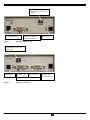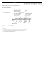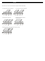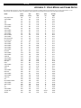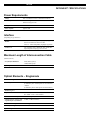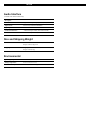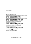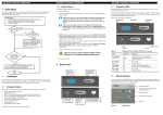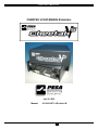
1
CHEETAH V5 MODULES
CHEETAH V5 DVI/RGBHV Extenders
July 26, 2005
Manual:
81-9059-0571-0 Revision B
1
CHEETAH V5 MODULES
81-9059-0571-0 REV.B
Copyrights and Trademarks
©2004. All rights reserved. This information may not be reproduced in any manner without the prior written consent of the manufacturer.
Information in this document is subject to change without notice and the manufacturer shall not be liable for any direct, indirect, special, incidental or
consequential damages in connection with the use of this material.
All trademark and trade names mentioned in this document are acknowledged to be the property of their respective owners.
Disclaimer
While every precaution has been taken in the preparation of this manual, the manufacturer assumes no responsibility for errors or omissions. Neither does
the manufacturer assume any liability for damages resulting from the use of the information contained herein. The manufacturer reserves the right to
change the specifications, functions, or circuitry of the product without notice.
The manufacturer cannot accept liability for damage due to misuse of the product or due to any other circumstances outside the manufacturer’s control
(whether environmental or installation related). The manufacturer shall not be responsible for any loss, damage, or injury arising directly, indirectly, or
consequently from the use of this product.
Cautions and Notes
The following symbols are used in this guide:
CAUTION. This indicates an important operating instruction that should be followed to avoid any potential
damage to hardware or property, loss of data, or personal injury.
NOTE. This indicates important information to help you make the best use of this product.
2
DECLARATION OF CONFORMITY
EUROPEAN UNION DECLARATION OF CONFORMITY
This is to certify that, when installed and used according to the instructions in this manual, together with the specified cables and the maximum
cable length <3m, the Units are shielded against the generation of radio interferences in accordance with the application of Council Directive
89/336/EEC as well as these standards:
EN 55022:
Fiber+STP
1999
Class B
EN 55022:
UTP
1999
Class A
EN 55024:
1999
IEC 61000-4-2:
2001
IEC 61000-4-3:
2001
IEC 61000-4-4:
2001
EN 61000-3-2
2001
EN 61000-3-3
2002
The device was tested in a typical configuration with PC.
3
CHEETAH V5 MODULES
81-9059-0571-0 REV.B
Safety Precautions and Installation Guidelines
To ensure reliable and safe long-term operation, please note the following installation guidelines:
•
Only use in dry, indoor environments.
•
If the building has 3-phase AC power, try to ensure that equipment connected to the Local and Remote units is on the same phase.
•
Ensure that the system connected to the Local unit is connected to power ground.
•
Ensure that the monitor connected to the Remote unit is connected to power ground and does not use an isolated power supply.
•
The Remote unit, Local unit and any power supplies can get warm. Do not locate them in an enclosed space without any airflow.
•
Do not place a power supply directly on top of a unit.
•
Do not obstruct a unit’s ventilation holes.
To safeguard against personal injury and avoid possible damage to equipment or property, please
observe the following:
4
•
Only use power supplies originally supplied with the product or manufacturer-approved
replacements. Do not attempt to dismantle or repair any power supply. Do not use a power supply if
it appears to be defective or has a damaged case.
•
Connect all power supplies to grounded outlets. In each case, ensure that the ground connection is
maintained from the outlet socket through to the power supply’s AC power input.
•
Do not attempt to modify or repair this product, or make a connection from the Fiber link interface
(LC) to any other products, especially telecommunications or network equipment.
SAFETY PRECAUTIONS AND INSTALLATION GUIDELINES
Optical Models
These are Class 1 Laser products. Singlemode transceivers comply with IEC 60825-1 and FDA 21 CFR 1040.10 and 1040.11. To meet laser safety
requirements, the transceivers shall be operated within the absolute maximum ratings.
The use of optical instruments with this product may cause an eye hazard. All adjustments have been
made at the factory prior to shipment of the device. No maintenance or alteration to the device is
required.
Tampering with or modifying the performance of the device will result in voided product warranty.
Usage Restrictions
Optical ports must be terminated with an optical connector or with a dust plug. Failure to adhere to the above restrictions could result in a modification
that is considered an act of “manufacturing” and will require, under law, recertification of the modified product with the U.S. Food and Drug
Administration (ref. 21 CFR 1040.10(i)).
5
CHEETAH V5 MODULES
81-9059-0571-0 REV.B
Contents
1. Quick Setup
1.1
Video Input/Output
1.2
Command Summary
7
8
9
2. Overview
2.1
Introduction
2.2
Glossary
2.3
Features
2.4
Product Range
2.5
Compatibility
2.6
How to Use This Guide
9
9
10
13
14
15
16
3. Installation 16
3.1
Package Contents
3.2
Interconnection Cable Requirements
3.3
System Setup
3.4
Diagnostic LEDs
16
17
18
20
4. Device Control
Opening the OSD
4.1
4.2
Using the OSD
20
22
24
5. Monitor Setup
32
6. Extender Setup
6.1
Overview
6.2
Setup Instructions for VGA Input
33
33
34
7. Troubleshooting
7.1
Video
35
35
Appendix A: Rack Mount Options
38
Appendix B: System Upgrade
40
Appendix C: Video Modes and Frame Rates
41
Appendix D: Audio Option
43
Appendix E: Calling Technical Support
45
Appendix F: Specifications
46
Appendix G: Connectors and Cables
48
6
QUICK SETUP
This section briefly describes how to install your Cheetah V5 system and optimize the video signals. Unless you are an experienced user, we recommend
that you follow the full procedures described in the rest of this manual. Refer to the command summary on page 9 when following this procedure.
Install system
1.
2.
3.
4.
Connect Remote unit (RX) to source.
Connect Local unit (TX) to CPU or switch.
Connect Local and Remote units with matching interconnection cable
(Singlemode fiber).
Power up the system.
No
Do you have a
DVI monitor?
Yes
No
Do you
have a flat screen
(TFT)?
Yes
Carry out the Monitor Setup
procedure (please refer to its
manual and see page 40 in
this manual).
Do you have a
DVI source?
Yes
No
Carry out VGA Input Setup procedure
(please follow the instructions on page 42).
Done
7
CHEETAH V5 MODULES
81-9059-0571-0 REV.B
VIDEO INPUT/OUTPUT
If possible, always use DVI output from your computer’s video card and DVI input to a monitor. This provides the optimum video signal. If you use a
VGA output from your graphic source, the DVI Local unit must digitize the signal prior to transmission. Similarly, if your remote TFT screen uses a
VGA input, it must digitize the signal from the Remote unit. In both cases, the built-in video processors must determine the resolution and pixel phase for
an optimized digitization. Your DVI Extender allows you to optimize the video signal manually or automatically using its on-screen utility (see Chapter
4). If you are using a VGA input to a TFT monitor, please follow the manufacturer’s instructions.
You may have several possible options for video source output/monitor input. If this is the case, for the optimum video quality, please select the highest
ranked available combination from the following table:
8
Video Quality
Local Unit input
Remote Unit output
1
DVI
DVI
2
DVI
VGA
3
VGA
DVI
4
VGA
VGA
COMMAND SUMMARY
The following table summarizes the ‘hot’ key command sequences used in system configuration and video tuning on a Remote unit console.
Command
Keyboard
at Remote unit
Terminal or
Windows Utility program*
Enter OSD
<Left Control>
+ <Left Shift> + <I>
<O> + <S> + <D>
+ <Enter>
Exit OSD
<ESC>
<X>
Select next position
<Right Arrow>
<R>
Select previous
position
<Left Arrow>
<L>
Select Submenu
<Enter>
<S>
Select parameter
modification
<Enter>
<S>
Increase parameter
<Right Arrow>
<R>
Decrease parameter
<Left Arrow>
<L>
Accept and store
modified parameter
<Enter>
<S>
Back to the Menu
selection
* Commands are not case-sensitive.
OVERVIEW
INTRODUCTION
A basic Cheetah V5 system comprises a Local unit (transmitter) and a Remote unit (receiver). The Local unit connects directly to the computer using the
supplied cable(s). The user console (monitor) attaches to the Remote unit. The Remote and Local units communicate video information along the
interconnecting cable (see Figure 1). Local units offer dual access, allowing the connection of a second user console close to the computer. With the
optional V5A2 models, you can also use the Cheetah V5 units to communicate stereo audio.
Cheetah V5 modules enable high-resolution video and optional stereo audio to be communicated up to:
•
1200ft (400m) over Multimode fiber cable (50/125µ).
•
600ft (200m) over Multimode fiber cable (62.5/125µ).
•
6¼ miles (10km) over Singlemode fiber cable (9/125µ).
In a digital application (DVI input and output), there is no loss of picture quality irrespective of extension distance and no adjustments are required. The
Cheetah V5 modules also support traditional analog VGA as well as digital DVI. All combinations of DVI and VGA (graphics cards and monitors) are
supported, allowing equipment to be mixed. In a mixed analog/digital application, some adjustment of the video signal is necessary to optimize the
analog-digital signal conversions. Cheetah V5 modules are equipped with various automatic and manual video correction tools in an on screen utility (see
page 20).
9
CHEETAH V5 MODULES
GLOSSARY
The following terms are used in this guide:
Multimode
Any multimode fiber cable 50/125µ or 62.5/125µ
Singlemode
Any singlemode fiber cable 9/125µ
PSU
The desktop power supply connected to the Local/Remote unit.
Dual Access
A system allowing connection of Local and Remote user consoles.
Single Head
An extender system that supports one monitor.
Coax
Recommended coax is Belden 8281 or equal
10
81-9059-0571-0 REV.B
Local Access
LOCAL unit
REMOTE unit
Audio extension
options
Video Support
Figure 1
Cheetah V5 System
11
CHEETAH V5 MODULES
12
81-9059-0571-0 REV.B
FEATURES
The Cheetah V5 Modules offer the following features:
•
Support for high video resolution over extended distances:
1600x1200@60Hz over all allowed distances
all lower resolutions with refresh rates of at least 75Hz
•
All models come with dual access, to allow local or remote operation
(Local DVI access limited to screen resolutions up to 1280x1024).
•
All control and video tuning carried out using an on screen display (OSD) with settings stored in EEPROM memory.
•
Local/Remote unit firmware and settings flash upgradeable.
•
Stereo audio (16-bit digitized) support on certain models enables high-quality, low-noise audio extension.
•
Status indicator LEDs on each device.
•
Small footprint chassis.
•
Rack mount options available.
•
CPU cables + Adapters included.
13
CHEETAH V5 MODULES
PRODUCT RANGE
There are two products in the ranges:
Primary Modules- Video Only
CH1612TX-V5
DVI/VGA Extender, Singlemode Transmitter
CH1612RX-V5
DVI/VGA Extender, Singlemode, Receiver
CH1612TX-V5C
DVI/VGA Extender, Coax, Transmitter
CH1612RX-V5C
DVI/VGA Extender, Coax, Receiver
CH1612TX-V5R
DVI/VGA Extender, Singlemode, Transmitter, Rackmount
CH1612RX-V5R
DVI/VGA Extender, Singlemode, Receiver, Rackmount
CH1612TX-V5CR
DVI/VGA Extender, Coax, Transmitter, Rackmount
CH1612RX-V5CR
DVI/VGA Extender, Coax, Receiver, Rackmount
Primary Modules-Video and Audio
CH1612TX-V5A2
DVI/VGA Stereo Audio, Singlemode Transmitter
CH1612RX-V5A2
DVI/VGA Stereo Audio, Singlemode Receiver
CH1612TX-V5A2C
DVI/VGA Stereo Audio Extender, Coax, Transmitter
CH1612RX-V5A2C
DVI/VGA Stereo Audio Extender, Coax, Receiver
CH1612TX-V5A2R
DVI/VGA Stereo Audio Extender, Singlemode, Transmitter, Rackmount
CH1612RX-V5A2R
DVI/VGA Stereo Audio Extender, Singlemode, Receiver, Rackmount
CH1612TX-V5A2CR
DVI/VGA Stereo Audio Extender, Coax, Transmitter, Rackmount
CH1612RX-V5A2CR
DVI/VGA Stereo Audio Extender, Coax, Receiver, Rackmount
Upgrade Kits
CHV5RMKIT
Rack mount kit for above modules, 1RU, supports up to three modules
CHV5-DVICABLE
Cable DVI
CHV5RMKIT3RU
3RU Frame, allows for up to 9 modules of any “-R” model. Internal power supply
and cooling fan.
14
81-9059-0571-0 REV.B
COMPATIBILITY
Interface Compatibility
•
(OPTION) Audio: Input and output are line-level. Amplified speakers are required.
•
Analog Video: VGA to UXGA. Supports RGB, RGsB, RGBHV. Maximum resolution and refresh rates depend on cable length and cable type
•
Digital Video: DVI single link for resolution up to 1600x1200 at 60Hz. Frame rates and colors depend on device type
15
CHEETAH V5 MODULES
81-9059-0571-0 REV.B
HOW TO USE THIS GUIDE
This guide describes the installation and configuration of the Cheetah V5 modules. Although the connection and operation of the system is relatively
straightforward, you should consider the following before getting started:
Connection & Compatibility
If you have purchased an Extender Kit, this will contain all the cables required to connect the Local unit to your PC. The Remote monitor and any audio
connects directly to the Remote unit.
For information about connection and installation, see Installation, page 16.
Interconnection Cable
For Cheetah V5 connections, use singlemode or multimode fibers (see Interconnection Cable Requirements, page 17.
Adjusting Video
Due to the digital nature of the transmitted signals, there is no distortion of video signals or skew problem.
If you do not have a DVI source and a DVI monitor, you will need to adjust the monitor and/or the Extender to the picture width and the pixel phase. You
can do this using the Auto Adjust or Manual Adjust procedures.
•
For experienced users there is a Quick Setup section at the start of this guide
(see page 7).
•
For the full procedure, see Monitor Setup and/or Extender Setup.
INSTALLATION
For first-time users, we recommend that you carry out a test placement, confined to a single room, before commencing full installation. This will allow
you to identify and solve any cabling problems, and experiment with the Cheetah V5 system more conveniently.
PACKAGE CONTENTS
You should receive the following items in your extender package (all types):
•
Extender Remote unit.
•
6V DC 12W universal power supply for Remote unit.
•
Extender Local unit.
•
6V DC 12W universal power supply for Local unit.
•
2x DVI-I to VGA adapter (DVI-I dual link male to HD15 female) connector.
•
1x VGA to DVI-I adapter (HD15 male to DVI-I dual link female) connector.
•
Programming cable (DB9 female to RJ11 4p4c).
•
User manual.
•
2x US-type power cord.
If anything is missing, please contact Technical Support (see Appendix E: Calling Technical Support).
16
INTERCONNECTION CABLE REQUIREMENTS
To connect the Local and Remote units you will need:
•
Multimode Modules: single fiber cable 50µm or 62.5µm.
•
Singlemode Modules: single fiber cable 9µm.
•
Coax Modules: single coax cable, 8281 Belden or equal type coax.
•
•
Power Supply
Connect the supplied 6V/DC power supplies to the Plug terminal on the rear of both Local and Remote units.
17
CHEETAH V5 MODULES
81-9059-0571-0 REV.B
SYSTEM SETUP
To install your Cheetah V5 system:
1.
Switch off all devices.
2.
Connect your monitor to the Remote unit
3.
Connect the interconnect cable to the INTERCONNECT socket(s) as shown
4.
Connect the 6V power supply to power the unit.
Only use the power supply originally supplied with this equipment or a manufacturer-approved
replacement.
5.
18
Power up the system.
INTERCONNECT – carries video
and data signals – connect to
Local unit
Programming connector –
for firmware upgrades
Figure 2
DVI-I Connector – DVI and
VGA output – connect to
Remote console monitor
Connect 6V
Power supply
Cheetah V5 Remote Unit
INTERCONNECT – carries video
and data signals – connect to
Remote unit
Connect 6V
Power supply
Connect to Local
console monitor
Connect to CPU
video card output
DVI-I Connectors (Digital or Analog)
Figure 3
Programming
connector – for
firmware upgrades
Cheetah V5 Local Unit
19
CHEETAH V5 MODULES
81-9059-0571-0 REV.B
DIAGNOSTIC LEDS
Each Extender unit is fitted with four indicator LEDs: Communication Error, Link Status, Device Ready and Video Signal. The Indicator LEDs are
located in the same positions on all models. The Communication Error and Link Status LEDs are to the left and right, respectively, of the Interconnect
sockets. The Device Ready and Video Signal LEDs are next to the Power socket.
As an example, the location of the LEDs is shown below for Remote and Local units:
Communication Error
Video Signal
(Green)
Figure 4
Link Status
Device Ready
(Red)
Communication Error
Device Ready
(Red)
Link Status
Video Signal
(Green)
Diagnostic LEDs on Remote (left) and Local (right) units
LED
Appearance
Diagnostics
Communication
Error
Off
Flashing
No communication error for >60 minutes
Indicates number of communication errors during
previous 60 minutes:
1-2
(Fiber)
3-10
(Fiber)
10
(Fiber)
slow
medium
fast
Error counter cleared automatically 60 minutes after previous communication error.
Link Status
On
Flashing
Link connection is locked
Interconnection cable not connected or not
functioning
Device Ready
(Red LED)
Off
On
Device not ready
Device ready
Video Signal
(Green LED)
Off
On
No video signal or valid mode detected
Attached and valid mode detected
DEVICE CONTROL
If you are using the DVI output from your video card and the DVI input to a TFT monitor, no adjustment should be required. In other cases, when the
video signal is converted between analog and digital formats, either by the Local unit and/or the monitor, you may need to optimize the video signal using
the Extender’s on-screen display (OSD).
Version information
Screen resolution and
refresh rate
Main menu icons
Submenu/command icons
Menu title
20
Figure 5
OSD Utility
You can adjust the following properties using the OSD:
•
Adaptation to analog signal sources (VGA/RGB) – see also Monitor Setup, page 32.
•
Color temperature
•
Brightness/contrast
•
Saturation
•
OSD operation, factory reset.
21
CHEETAH V5 MODULES
81-9059-0571-0 REV.B
OPENING THE OSD
You can access the OSD in two ways:
•
Using a standard terminal program with a serial connection to the programming port.
•
Using our small WINDOWS™ program with a serial connection to the programming port.
While the OSD is active, the mouse is locked and only menu keystrokes are allowed at the keyboard. To indicate that the OSD mode is active, the status
LEDs (Num Lock, Caps Lock and Scroll Lock) are flashed. There is a summary of OSD commands on page 9.
Using a standard terminal program with a serial connection
On all devices, you can use a terminal (or terminal software) for OSD access:
1.
Connect the programming cable to the programming port of the Local (TX) unit.
2.
Connect the programming cable to the serial port of a computer running a terminal client.
3.
Set up the terminal to 115200 baud with 8 data bits, no parity and 1 stop bit, ASCII-mode.
4.
Type in the following key sequence:
< O > + < S > + < D > followed by <ENTER>
22
5.
When the OSD starts, it displays information about the attached device and firmware version, for example:
DVI-KVM-12lo
Vers.1.3
03/05/15
To navigate within the OSD:
•
Use the <L> and <R> keys to highlight a submenu and/or function.
•
Press the <S> key to select the highlighted submenu or function.
•
Select the Exit icon to go back to the previous menu level.
•
Press the <X> key to exit the OSD mode.
Using our WINDOWS™ program
On all devices, you can use our small WINDOWS™ program, running on a WINDOWS™ computer for OSD access:
1.
Install the OSD program from the supplied CD or download from our website under the pesa/downloads page
2.
Connect the programming cable to the programming port of the Local (TX) unit.
3.
Connect the programming cable to the serial port of your computer, where the program is running.
4.
Start the program and follow the on-screen instructions.
5.
Type in the following key sequence:
< O > + < S > + < D > followed by <ENTER>
When the OSD starts, it displays information about the attached device and firmware version, for example:
Modul Name
Version
Date
: DVI-KVM-12lo
: Vers.1.3
: 03/05/15
To navigate within the OSD:
•
Use the <L> and <R> keys to highlight a submenu and/or function.
•
Press the <S> key to select the highlighted submenu or function.
•
Select the Exit button to go back to the previous menu level.
•
Press the <X> key to exit the OSD mode.
23
CHEETAH V5 MODULES
81-9059-0571-0 REV.B
USING THE OSD
The OSD is an icon-based utility. The top line of symbols shows the main menu categories:
Input Select
Specify whether the input is analog (VGA) or digital (DVI)
Scale Mode
Choose whether transmission occurs at the original screen resolution
(“transparent”) or the Extender imposes a fixed resolution.
Brightness – Contrast
Adjust brightness or contrast or reset to default values.
Color
Adjust color calibration, temperature, flesh/skin tone, hue and saturation.
Image
VGA Input source only - Adjust pixel clock and phase.
Tools
Set OSD position and size, fixed scale sharpness, color depth, factory reset.
1.
Use the left and right arrow keys (<L> and <R> keys on terminal or in Windows program) to highlight the icon you want. The OSD displays
additional icons relating to commands in the selected menu category.
2.
Press the Enter key (<S> key on terminal or in Windows program). The OSD highlights the first command icon.
3.
Use the Left and Right arrow keys (<L> and <R> keys on terminal or in Windows program) to highlight the command or submenu you want. In the
case of the latter, your selection will cause the OSD to display additional command icons (Color Temperature commands, for example).
4.
Press the Enter key (<S> key on terminal or in Windows program) to accept a highlighted command. If this requires the increase or decrease of a
value (Contrast, for example), the OSD displays a value bar:
5.
24
+
Use the Left and Right arrow keys (<L> and <R> keys on terminal or in Windows program) to change the value as required.
6.
In many cases, after you have chosen a new setting, the OSD displays the following confirmation message:
7.
Highlight the Yes button and press the Enter key (<S> key on terminal or in Windows program) to confirm your choice. Alternatively, highlight the
No button and press the Enter key (<S> key on terminal or in Windows program) to discard the new setting and restore the previous value.
8.
Select the Exit icon to close a submenu.
9.
Press the Esc key (<S> key on terminal or in Windows program) to close the OSD, saving all settings, and restore normal mouse and keyboard
functions.
The following table summarizes the keyboard actions and icons used to navigate the OSD utility, and to select and adjust the Extender’s parameters:
Key/Icon
Remote Keyboard
Terminal or
Windows program
Esc
<X>
Action
Close the OSD, restore normal keyboard and
mouse functions.
Return to previous Menu selection.
Enter
<S>
Open the highlighted menu or submenu
Accept the highlighted command
Left arrow
<L>
Select the previous menu or command icon
Decrease the highlighted parameter
Right arrow
<R>
Select the next menu or command icon
Increase the selected parameter
25
CHEETAH V5 MODULES
81-9059-0571-0 REV.B
Input Select
Some graphic cards are equipped with both DVI and VGA outputs. On powering up the CPU, the Extender system uses the first detected signal
unless you explicitly specify the input type. Use the Input Select menu to specify the type of video signal to be used by the Local unit. The
actual graphic source is displayed with a ‘[’ symbol (for example, VGA[).
VGA Video input to Local unit
DVI Video input to Local unit
Return to main menu
Figure 6
26
Input Select menu
Scale
Use the Scale menu to specify whether the Extender system changes the resolution of the input video. You can set the device for transparent
transmission. In this case, the Remote unit generates a screen resolution and refresh rate to match that of the source. You can also specify that
the output displays at a fixed screen resolution, regardless of that of the input signal. You might want to use a fixed resolution if your monitor is
not able to display the generated resolution or, for example, if you have a server farm with many different CPUs each having a different screen resolution.
With a transparent transmission, it could take a long time to regain a picture on the screen each time you switch to a different CPU.
Transparent transmission: No modification
of resolution/refresh rate, Remote unit
always generates an exact reproduction of
the source signal
Choice of three fixed transmissions at
refresh rate of 60Hz (for LCD/flat screens)
800x600, 1024x768, 1280x1024
Return to main menu
Choice of three fixed transmissions at
refresh rate of 75Hz (for CRT/tube screens)
800x600, 1024x768, 1280x1024
Figure 7
Scale Mode menu
Downscaling is only available with VGA signals. With a DVI input, you can select downscaling but it will not work – only upscaling has an effect.
27
CHEETAH V5 MODULES
81-9059-0571-0 REV.B
Brightness/Contrast
Use this menu to adjust the brightness and contrast of the video image, or to adjust the black level of an LCD display.
Adjust Brightness
Adjust Contrast
Adjust Black level
Return to main menu
Figure 8
Brightness-Contrast menu
Select Colors and Color Temperatures
Use the Colors menu to adjust the color balance of the video image. The menu provides a number of options including automatic calibration,
manual adjustment in RGB or CMY color space, hue and saturation adjustment and the setup of flesh/skin tone.
Automatic color calibration
Standard RGB color selection
View Color temperature submenu
(see Color Temperature, page 36)
Flesh tone/Skin tone
Hue
Figure 9
28
Saturation
Color menu
Set up colors in CMY space – automatically
adjusts
settings in RGB space
Back to main
menu
Color Temperature
Use the Color Temperature submenu to set up the color profile in RGB color space or by using one of five predefined color temperatures. To
view this menu, select the Colors icon from the main menu and then select the Color Temperature icon.
Set up colors in RGB space – automatically
adjusts settings in CMY space
Choice of five color temperature settings:
4200k, 5000k, 6500k, 7500k, 9300k
Back to Color menu
Figure 10
Color Temperature submenu
Image
VGA inputs only
Use the Image menu to adjust the vertical and horizontal screen position and to set the pixel clock and phase.
Automatic detection of the number of pixels
per line and the best phase (best point for
A/D conversion within each pixel) see also
Extender Setup, page 41.
Back to main menu
Manually adjust the vertical screen position
Manually adjust the horizontal screen
position
Manually adjust the
number of pixels per
line (Pixel clock)
Figure 11
Manually adjust the best phase (best point for A/D
conversion within each pixel)
Image menu
29
CHEETAH V5 MODULES
81-9059-0571-0 REV.B
Tools
Use the Tools menu to set the position and size of the OSD window, adjust the sharpness for a fixed resolution setting, set the color depth, reset
the Extender system to its factory default settings or provide a test pattern.
Set the position of the OSD window (see
OSD, page 37)
Reset Extender to factory default settings
Adjust sharpness (fixed resolution modes
only). When resolution is changed by an
imposed fixed resolution, sharpness can be
affected. Use this option to switch between
three settings for optimum sharpness
Select color depth
(see Color Depth, page 39)
Display a ‘burst’ pattern at the
remote console for monitor setup
(see Monitor Setup, page 42)
Choose whether to automatically
adjust pixels per line and pixel
phase after a mode change
(see Auto Configuration, page 38)
Back to main menu
Figure 12
Tools menu
OSD
Use the OSD submenu to define the position and size of the OSD window. To view this menu, select the Tools icon from the main menu and
then select the OSD icon.
Manually adjust the horizontal position of
the OSD window
Manually adjust the vertical position of the
OSD window
Back to Tools menu
Toggle the size of the OSD window
between single and double size
Figure 13
30
OSD submenu
Auto Configuration
Use the Auto Configuration submenu to define whether the Local unit carries out automatic detection of the number of pixels per line and the
best phase after a mode change (a change of screen resolution and/or refresh rate at the graphic source). Using automatic detection (while
displaying an appropriate test pattern) ensures an optimized image but the procedure introduces a delay in the picture appearing on the remote
console screen. If you want the picture to appear as fast as possible, and can tolerate a non-optimized image, you may want to disable this
feature. Please note that Auto Configuration is disabled in the default factory settings.
To view the Auto Configuration menu, select the Tools icon from the main menu and then select the Auto Configuration icon.
Disable Automatic detection of pixels per
line and phase after a mode change
Enable Automatic detection of pixels per
line and phase after a mode change
Back to Tools menu
Figure 14
Auto-Configuration submenu
31
CHEETAH V5 MODULES
81-9059-0571-0 REV.B
Color Depth
Use the Color Depth submenu to select the color depth of the transmitted screen picture. Transmissions can be in high color mode or low color
mode. High color mode produces a better quality image but results in a lower frame rate (fps). Use low color mode if you require fast screen
changes, for example video applications. Use high color mode if you need precise images, for example, medical applications. Please see
Appendix C: Video Modes and Frame Rates (page 41) for more information about frame rates and supported screen resolutions.
Color Depth
Color Mode
Fiber
Low
6 bits/color
18 bits total
262144 colors
High
8 bits/color
24bits total
16.78M colors
To view this menu, select the Tools icon from the main menu and then select the Color Depth icon.
Select low color mode/higher fps
Select high color mode/lower fps
Back to Tools menu
Figure 15
Color Depth submenu
MONITOR SETUP
This procedure is designed to correct for discrepancies in the video signal due to analog/digital video conversion by the Monitor. You do not need to
follow this procedure if you have:
•
A CRT monitor connected to the Remote unit through the VGA input
•
A TFT monitor connected to the Remote unit through the DVI input
In these cases, there is no need to adjust the monitor because the video format is not converted.
Please make sure that you carry out this procedure before Extender Setup (page 33). If you are using a TFT monitor at the remote console with a VGA
cable, both the Extender AND the TFT monitor digitize the video data stream and affect video quality. By setting up the TFT monitor first, you ensure
that you are correcting discrepancies due solely to the Extender system in the Extender Setup procedure.
1.
Connect the Extender system and display the regular desktop in the desired screen resolution. Monitor setup may vary depending on screen
resolution and/or refresh rate.
2.
Display the OSD utility (see page 22).
3.
Select the Tools menu option (see page 30).
4.
Select the ‘burst’ pattern option. Your TFT should show fine, 1 pixel wide, black and white vertical stripes over the entire screen. The OSD will stay
visible in the middle of the screen.
5.
Depending on the type of TFT, press the ‘AUTO’ Button on the monitor control panel or select Auto Adjust in the TFT Setup Menu. Refer to the
manual supplied with your monitor for more information.
6.
If the vertical stripes are sharp and without jitter or smearing, the adjustment has been successful. Go to step 8.
32
7.
If the picture quality is not acceptable after the automatic adjustment, you will have to manually adjust the pixel clock and pixel phase (in this order).
Please follow the instructions in your monitor’s user manual.
8.
Press any key to exit the test pattern display.
9.
Exit the OSD.
EXTENDER SETUP
OVERVIEW
You need to optimize the video signal across your Extender system if it undergoes one or more conversions between analog and digital formats. The
exact procedure depends on your Extender setup:
Graphics
card
Monitor
type
Monitor
Input used
Video Optimization Procedure(s)
TFT adjustment (see Monitor Setup, page 32)
Optimization using OSD
(see Setup Instructions for VGA Input, page 34)
VGA
TFT
VGA
VGA
CRT
VGA
Optimization using OSD
(see Setup Instructions for VGA Input, page 34)
VGA
TFT
DVI
Optimization using OSD
(see Setup Instructions for VGA Input, page 34)
DVI
TFT
VGA
TFT adjustment only
(see Monitor Setup, page 32)
DVI
CRT
VGA
No setup required
DVI
TFT
DVI
No setup required
33
CHEETAH V5 MODULES
81-9059-0571-0 REV.B
SETUP INSTRUCTIONS FOR VGA INPUT
This procedure is designed to correct for discrepancies in the video signal due to analog/digital video conversion by the Extender system. You do not
need to follow this procedure if you have a DVI graphics card connected to the Local unit. In this case, the video signal remains in a digital format
through the Extender system.
If you are using a TFT monitor at the remote console with a VGA cable, you should carry out the Monitor Setup procedure first (see page 32). In this
configuration, both the Extender AND the TFT digitize the video data stream and affect video quality. By setting up the TFT monitor, you ensure that
you are correcting discrepancies due solely to the Extender system in this procedure. Alternatively, you could replace the TFT monitor with a CRT
monitor while you carry out this procedure. You can then reconnect the TFT monitor and optimize its video image afterwards.
1.
Download the test pattern from our web server:
This is a ‘burst-pattern’ (see Figure 20) - a picture with alternating, 1 pixel wide black and white, vertical stripes.
If you are unable to view the test card, display some black text on a white background. For example, you could open Notepad, maximize it to full
screen, and fill the page with letter ‘I’s in a 12pt font. Proceed with step 3.
2.
Select the burst-pattern graphic as desktop background for the PC:
From the Start menu, choose Settings | Control Panel | Display | Backgrounds.
Search for the downloaded burst file, using ‘Search for’.
Select the tiled display option.
Your desktop should show fine black and white vertical stripes over the entire desktop.
3.
Display the OSD (see page 22).
4.
Select the Image menu option:
5.
Select the first command icon:
Automatic detection of number
of pixels per line and the best phase.
6.
Assess the desktop test pattern. If the vertical stripes are sharp and without jitter or smearing, the adjustment has been successful. Go to step 10.
7.
If the picture quality is not acceptable after the automatic adjustment, you will have to manually adjust the pixel clock and pixel phase (in this order).
34
8.
9.
With a poorly adjusted pixel clock you may see one or more vertical areas, where the lines are smeared (see Figure 16a):
a.
Return to the OSD utility and select the menu command:
Manually adjust the number of pixels per line (Pixelclock)
from the Image menu.
b.
Adjust the pixel clock value until all stripes have disappeared.
c.
Confirm the setting.
Problems with the pixel phase will cause horizontal noise, horizontal wave-formed lines, flicker or smearing with zebra-pattern (see Figure 16b):
a.
From the OSD’s Image menu, select the menu command:
Manually adjust the best phase (best point for A/D conversion within each pixel).
b.
Modify the phase until all distortions have disappeared.
c.
Confirm the setting.
10. If appropriate, reattach your TFT monitor and adjust its image according to the manufacturer’s instructions.
11. Reinstall your preferred desktop background picture.
(a)
Figure 16
(b)
Burst test pattern applied to desktop showing problems with (a) pixel clock setting, (b) pixel phase setting.
TROUBLESHOOTING
VIDEO
There isn’t a picture.
Check the power supply connection at the Local unit. Is the Device Ready (Red LED) at the Local unit illuminated (see page 20)? If not, the
internal power-supply may be damaged or there may be an internal error.
Check the power supply connection at the remote unit. Is the Device Ready (Red LED) at the Remote unit illuminated (see page 20)? If not, the
internal power-supply may be damaged or there may be an internal error.
Check that the Interconnection cable is connected at the Local Unit and the Remote Unit. Is the Link Status LED illuminated (see page 20)? If
not, there may be a problem with the Interconnection cable:
•
Fiber types: Check that the fiber optical cable is correctly connected. The strand connected to the Local Unit’s TX (left-hand connector)
must run to the Remote Unit’s RX (right-hand connector) and vice versa.
•
Fiber types: There may be one or more broken fibers. Do NOT look into a fiber’s end directly while it is connected to a Local or Remote
unit! Are the Link Status LEDs at the Local Unit AND at the Remote Unit illuminated? If they are flashing, check for broken fibers using a
flashlight.
•
Fiber types: Are the cables of the recommended fiber type? If you used your own fiber optical cable (not supplied by Black Box), please
ensure that you have used 50µ or 62.5µ fiber with a multimode device or a 9µ fiber with a singlemode device. Other fiber-types and polyfibers are not supported.
Check that you are using a supported video mode (see Appendix C: Video Modes and Frame Rates). At the Remote Unit, is the Video Signal
LED illuminated (see page 20)?
35
CHEETAH V5 MODULES
81-9059-0571-0 REV.B
Check your total system configuration. Local units digitize incoming VGA signals and must receive perfect SYNC signals: no glitches, spikes
or deformed signals are allowed. Long/wrong or bad cables, or additional components like Splitters or KVM Switches may deform the SYNC
signals.
Also check that the signals (level and signal form) match the VESA Standard requirements.
36
There is horizontal jitter on the picture.
The pixel clock and/or phase is misaligned: Refer to page 34.
Characters are smeared.
The phase is misaligned: Refer to page 34.
Thin vertical lines are missing.
The phase is misaligned: Refer to page 34.
Colored areas of the screen look like an oil film.
In some circumstances, the Extender’s internal video processor may lose its firmware. In this case, it is necessary to reset the unit. A power
cycle is NOT sufficient! Please use the OSD to make a Factory Reset (see page 30).
37
NOTES
APPENDIX A: RACK MOUNT OPTIONS
Extender units can be mounted in a 19” rack using the mounting kit:
CHV5RMKIT-Rackmount Kit
This contains the following parts:
Narrow strip
Two small blanking plates
Wide blanking plate
Base plate
M3x5 Screws (14)
Figure 17
Rack Mounting Kit
To mount a unit:
1.
Align the holes on the base plate with the vacant screw holes on the base of the extender unit.
2.
Fasten the base of the unit to the plate of the mounting kit using the supplied screws.
3.
Close the remaining gaps with blanking plates.
NOTES
The kit allows you to mount various combinations of regular and double width housings:
1. One regular unit (using two small plates)
2. Two regular units (using one small plate)
3. Mounting of three regular units
4. Mounting of one double width unit
(using wide plate)
5. Mounting of double width and regular units ( using narrow strip)
NOTES
APPENDIX B: SYSTEM UPGRADE
System Update / Onboard Programming
It is occasionally necessary to update the firmware of the system. Normally, this procedure is carried out in the factory. If you want to update the
firmware yourself, contact Technical Support. You will need a programming cable and software to carry out the update. Please follow the supplied
instructions carefully.
NOTES
APPENDIX C: VIDEO MODES AND FRAME RATES
The following table shows the video modes supported by the Cheetah V5 modules and the expected frame rates over fiber interconnects or coax
interconnects. The Extenders are able to synchronize video modes that do not differ by more than 10% from those listed below.
Name
Horiz
Vert
Horiz
Vert
Dot Clk
Pixels
Lines
kHz
Hz
MHz
DOS graphic Mode
640
350
31.43
70
25.14
Vesa Standard
640
350
37.83
85
31.47
VGA
640
400
24.64
56
20.89
VGA
640
400
31.43
70
25.14
Vesa Standard
640
400
37.86
85
31.50
Vesa Standard
640
480
31.47
60
25.18
Mac Mode
640
480
35.18
67
31.52
Vesa Standard
640
480
37.44
72
31.15
Vesa Standard
640
480
37.50
75
31.50
Vesa Standard
640
480
43.27
85
36.00
DOS Text Mode
720
400
31.43
70
28.29
Vesa Standard
720
400
37.93
85
35.50
NTSC progressive
720
480
31.50
60
27.03
PAL progressive
720
576
31.25
50
27.00
Vesa Standard
800
600
35.16
56
36.00
Vesa Standard
800
600
37.88
60
40.00
Vesa Standard
800
600
48.08
72
50.00
Vesa Standard
800
600
46.88
75
49.50
Vesa Standard
800
600
53.67
85
56.25
Mac Mode
832
624
49.50
75
55.44
Vesa Standard
1024
768
48.36
60
65.00
Vesa Standard
1024
768
56.48
70
75.00
SUN Mode
1024
768
58.03
72
75.21
Vesa Standard
1024
768
60.02
75
78.75
Vesa Standard
1024
768
68.68
85
94.50
DMT1185
1152
864
63.49
70
100.06
Mode
1152
864
63.84
70
94.48
Vesa Standard
1152
864
67.50
75
108.00
SUN Mode
1152
900
61.84
66
94.49
VESA
1280
768
48.12
60
81.23
Vesa Standard
1280
960
60.00
60
108.00
DMT127A
1280
960
75.00
75
126.00
Vesa Standard
1280
960
85.94
85
148.50
Vesa Standard
1280
1024
63.98
60
108.00
SUN mode
1280
1024
70.95
66
115.79
SGI
1280
1024
76.68
72
128.82
HP Workstation B123L
1280
1024
78.12
72
135.00
Vesa Standard
1280
1024
79.98
75
135.00
Vesa Standard
1280
1024
91.15
85
157.50
TV
1400
1050
64.92
60
122.05
SGI
1600
1024
77.62
72
158.34
Vesa Standard
1600
1200
75.00
60
162.00
TV Mode 16:9
1920
1080
66.59
59.934
138.50
WUXGA
1920
1200
74.04
59.95
154.00
NOTES
Frame Rates (FPS)
The Cheetah V5 is not capable of transferring every frame generated by a graphics card because the net data rate of a Single Link DVI-Interface with
3.9Gbit is much higher than the available transfer rate of the Extenders.
Transmission follows the following scheme:
•
Starting with a recognized VS-Signal, the first frame is digitized (on VGA) and temporarily stored (DVI+VGA) by the Local unit.
•
The data are transmitted, using the available net data rate, to the Remote unit. During this time, frames generated by the graphic card are discarded
without any recognition (frame dropping).
•
When data transfer is complete, the Extender system waits for the next VS-Signal.
Depending on the data volume (affected by the selected screen resolution/refresh rate), the type of transmission module and the correspondence between
the duration of the data transfer and a multiple of the refresh rate, you should get frame rates in a range of approximately 15 fps up to the actual refresh
rate of the graphic card.
The frame rate counts the number of different pictures that are displayed in one second. The monitor is always driven with the
same refresh rate as generated by the graphics card or selected in the OSD.
The human eye is not able to discern more than 15 fps as single pictures. Your Cheetah V5 modules are therefore suitable for displaying streaming video
in the highest resolution. To gain a higher frame rate, reduce the screen resolution - video normally does not require higher resolutions.
NOTES
APPENDIX D: AUDIO OPTION
The Audio option consists of daughter boards that allows for stereo audio to be sent across the regular interconnection cable in addition to VGA/DVI
video.
To set up the extender’s audio, please follow all of the instructions detailed in this appendix. If you have any questions, contact Technical Support.
NOTES
Optional Audio Interface - Set Up and Operation
The audio interface is line-level and is designed to take the output from a sound card (or other line-level) source and be connected to a set of powered
speakers at the other end of the link. Stereo audio may be transmitted over the same fiber link as the video. No set up is required to the remote unit.
Connect up the extender as follows:
Take the line-level output from your sound card (green connector) and connect to ‘Line In’ on the extender.
A set of powered speakers may be connected directly to ‘Line Out’ at the opposite end of the link.
NOTES
APPENDIX E: CALLING TECHNICAL SUPPORT
If you determine that your Cheetah V5 modules are malfunctioning, do not attempt to alter or repair it. It contains no user-serviceable parts. Contact
Technical Support
Before you do, make a record of the history of the problem. We will be able to provide more efficient and accurate assistance if you have a complete
description, including:
•
The firmware-revision level printed on the bottom of the Extender (very important);
•
The nature and duration of the problem.
•
When the problem occurs.
•
The components involved in the problem—that is, what type of computers, what type of keyboard, brand of mouse, make and model of monitor,
type and make of cable, etc.
•
Any particular application that, when used, appears to create the problem or make it worse.
•
The results of any testing you’ve already done.
To solve some problems, it might be necessary to upgrade the Extender’s firmware. If this turns out to be the case for your difficulty, our Technical
Support technicians will arrange for you to receive the new firmware and will tell you how to install it.
Shipping and Packaging
If you need to transport or ship your Cheetah V5 modules:
•
Package it carefully. We recommend that you use the original container.
•
If you are shipping it for repair, please include the Unit’s external power supplies. If you are returning it, please include everything you received
with it. Before you ship the Extender back to your dealer for repair or return, contact him to get a Return Authorization (RA) number.
NOTES
APPENDIX F: SPECIFICATIONS
Power Requirements
Voltage
PSU: 90..240VAC-0.5A-47..63Hz/6VDC-2000 mA
Power required
Local Unit: approx. 8W
Remote Unit approx. 8W
Voltage
PSU: 90..240VAC-0.5A-47..63Hz/5VDC-2400 mA
Power required
approx. 10W
Interface
(Depending on type of device)
Monitor
VGA (res.: 1600x1200@60Hz, plug&play supported)
all lower resolutions at least with 75Hz
DVI (res.: 1600x1200@60Hz, plug&play supported)
Local Access
max. resolution VGA: 1600x1200, DVI: 1280x1024
output depends on input type VGA or DVI
Maximum Length of Interconnection Cable
(Without reboost)
62.5µm/50µm Multimode
650ft (200m) @62,5µ
1300ft (400m) @50µ
9µm Singlemode
6 ¼ miles (10km)
Optical Elements – Singlemode
Center Wavelength
1300nm
Total Output Power
<2000µW
(as defined by IEC: 50mm aperture at 10cm distance)
<180µW
(as defined by FDA: 7mm aperture at 20cm distance)
Beam Divergence
4°
Required Labels
FDA: Complies with 21 CFR 1040.10 and 1040.11
IEC: 60825-1 Class 1 Laser Product
Transmitter Electro-Optical Characteristics (typical)
Launched power (Average) into
singlemode fiber 9µm diameter
-3 dBm (-11dBm minimum)
Receiver Electro-Optical Characteristics (typical)
Sensitivity (Average Power)
-22dBm (-20dBm maximum)
Optical budget total
-18dBm (-8dBm minimum)
NOTES
Audio Interface
(Available with Audio modules only)
Description
stereo audio link
Transmission Method
Digitized virtually CD quality audio (16-bit, 38.4KHz)
Signal Levels
Line-Level (5 Volts P-P maximum)
Input Impedance
47K
Local Unit Connectors
3.5mm stereo jack socket (Line In & Line Out)
Remote Unit Connectors
3.5mm stereo jack socket (Line Out)
Size and Shipping Weight
Remote and Local Unit
Remote/Local Unit: 6.7”x5.2”x1.7” (170x133x44mm)
Weight: 2.2lb (1.0kg) each
Shipping box
Shipping Box: 18.1”x9.8”x4.7” (460x250x120mm)
Weight: 9.5lb (4.3kg)
Environmental
Operating Temperature
50 to 113°F (10 to 45 °C)
Storage Temperature
23 to 131°F (-5 to 55 °C)
Relative Humidity
max. 80% non-condensing
NOTES
APPENDIX G: CONNECTORS AND CABLES
Extender Connector Pinouts
DVI-I Female connector (on all units)
1
8
C1 C2
C5
17
Pin
Signal
24
Pin
C3 C4
Signal
Pin
Signal
1
T.M.D.S data 2-
9
T.M.D.S data 1-
17
T.M.D.S data 0-
2
T.M.D.S data 2+
10
T.M.D.S data 1+
18
T.M.D.S data 0+
3
T.M.D.S data 2 GND
11
T.M.D.S data 1 GND
19
T.M.D.S data 0 GND
4
n.c.
12
n.c.
20
n.c.
5
n.c.
13
n.c.
21
n.c.
6
DDC Input (SCL)
14
+5V Power
22
T.M.D.S clock GND
7
DDC Output(SDA)
15
GND
23
T.M.D.S clock +
8
Analog VSYNC
16
Hot Plug recognition
24
T.M.D.S clock -
C3
Analog Blue
C4
Analog HYSNC
C1
Analog Red
C2
Analog Green
C5
Analog GND
NOTES
Programming
1
4
Pin
Signal
1
TxD (to PC RxD)
2
RxD (from PC TxD)
3
DTR from PC
4
GND
Power
1
2
3
Pin
Signal
1
GND
2
Earth
3
n.c.
4
+6VDC
Housing
Shield
4
NOTES
Adapter Cables
DVI/VGA Adapter
Remote/Local Unit: DVI-I male connector
C2 C1
8
1
C4 C3
24
17
Monitor: HD15 female connector
C5
Pin
Signal
Pin
Signal
6
DDC Input (SCL)
15
DDC Input (SCL)
7
DDC Output(SDA)
12
DDC Output (SDA)
8
Analog VSYNC
14
Analog VSYNC
C1
Analog Red
1
Analog Red
C2
Analog Green
2
Analog Green
C3
Analog Blue
3
Analog Blue
C4
Analog HYSNC
13
Analog HSYNC
C5
Analog GND
6,7,8
Analog GND
NOTES
Local unit VGA/DVI Adapter
CPU Graphics card: HD15 male connector
Local Unit: DVI-I male connector
C2 C1
8
1
C4 C3
24
17
C5
Pin
Signal
Pin
Signal
15
DDC Input (SCL)
6
DDC Input (SCL)
12
DDC Output (SDA)
7
DDC Output(SDA)
14
Analog VSYNC
8
Analog VSYNC
1
Analog Red
C1
Analog Red
2
Analog Green
C2
Analog Green
3
Analog Blue
C3
Analog Blue
13
Analog HSYNC
C4
Analog HYSNC
6,7,8
Analog GND
C5
Analog GND