1
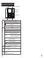
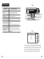
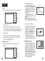
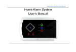
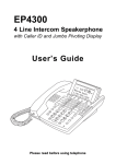
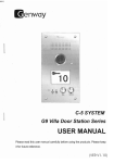
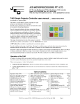
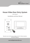
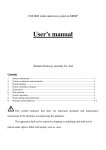
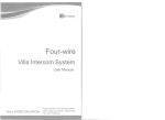
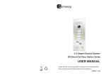
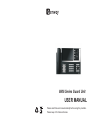
6806 Series Guard Unit
USER MANUAL
Please read this user manual carefully before using the products.
Please keep it for future reference.
Content
Announcement
Specification and performance data listed here are subject
1. PrefaÜÜÜÜÜÜÜÜÜÜÜÜÜce¡ ¡ ¡ ¡ ¡ ¡ ¡ ¡ ¡ ¡ ¡ ¡ ¡ ¡ ¡ 1
to change without notice.
2. ProduÜÜÜct FeaturÜÜÜÜes¡¡¡¡¡¡¡¡¡¡¡¡1
?. SpecificatioÜÜÜÜÜÜÜÜÜns¡¡¡¡¡¡¡¡¡¡¡¡¡¡1
4. Functions& Appearance ¡¡¡¡¡¡¡¡¡2
5. OperatioÜÜÜÜÜÜÜÜÜÜns¡ ¡ ¡ ¡ ¡ ¡ ¡ ¡ ¡ ¡ ¡ ¡ ¡ ¡ ¡ 4
6. SystÜÜÜÜem SettiÜÜÜÜng¡¡¡¡¡¡¡¡¡¡¡¡¡?
?. Troubleshooting¡¡¡¡¡¡¡¡¡¡¡¡ÜÜÜÜÜÜÜ14
VER:1.0
340302000780
Preface
Thank you for using Genway C-5 door entry system. Our
guard unit is the core device which is used to achieve the
intercom, monitor, alarm, access control function among
indoor phone, door station, perimeter gate station and the
other guard unit.
Product Features
¡Achiev: Video intercoming the video intercom between
user and the guard unit/visitor.
¡s status and'Monitor door station: Real time monitor
.s status'perimeter gate station
¡Receiv: Alarm messageing s message to'the alarm zone
.s safety'guarantee the community
¡Register the card: Register the card by different methods.
¡Optional(Send message to the indoor phone: Message sending(
Specifications
Operating voltage£DC V?0¡V?5
Quiescent current£¡12V?5(mA0(
Operating current£¡18V?5(mA0(
LCD screen£7£color LCD£Resolution£4?0¡234 L£
Video input: 1Vp_p/75¦;
Video output: ?5/p_Vp1¦;
Dimension(W/H/D): 357mm¡216mm¡71mm
16
1
Appearance & Functions
LCD display
Screen's function buttons
Indicator lights
F1
CARD
F2
F3
Card reader
F4
1
2
3
4
5
6
7
8
9
*
0
#
¹À»
ÊÄ»
Function buttons
OK
Short cut buttons
Numeric buttons
ÃÌ
¿Ë
MIC
Power supply indicator£This light flickers when power on.
Indicator
lights
Talk indicator light: This light is on when ringing, monitoring or talking.
Alarm indicator light: This light flickers when alarm message come or
hasn't been read.
Hand-free indicator light: This light is on when the guard unit is in the state
of hands free.
Call button (guard unit): Press this button, then input guard No. to call.
Function
buttons
Call button (indoor phone):Press this button, then input indoor phone No. to call.
Monitor button: Press this button, then input door station No. to monitor.
Message send button: Press this button to enter message sending
interface and send message to user.
Message check button: Press this button to enter message checking
interface to check alarm message, picture message,
voice message, unlock message and so on.
Backspace key: Press this button to hang up, return to previous menu or
delete the wrong input letter.
Hand-free button: Press this button to enter hand-free talking when in
ringing status or talking status.
Unlock button: Press this button to unlock the door station or perimeter gate station.
OK
2
Direction key: Press [ok] button to enter system setting interface, then
choose the up, down, left or right direction.
Numeric
buttons
Screen's
function
buttons
Digital button ranges from 0~9;
* button: Press this button to return the previous interface.
F1/F2/F3/F4: This part's buttons are in accordance with the left part's screen
function button.
Short cut
buttons
When in monitoring and calling operation, press the shortcut key to enter the
corresponding No..
(Note: The user can set 10 common used No..)
15
Troubleshooting
SYMPTOM
Side
POINTS TO CHECK
SWITCH VIDEO IN VIDEO OUT USB
No ringing
¡ Check whether you have set the
disturb type or not-device to anti.
Low talk volume
¡ Adjust the talk volume
No picture when talking
¡ chroma and contrast, Adjust the brightness
No voice when talking
¡ Check whether the sound hole is jammed
or not.
¡ Get close to microphone when talking.
¡ Device doesn't connect to the system.
Display No response
when adjust the chroma ¡ then, Operate the monitor operation first
proceed with the adjust of the chroma and
and brightness
brightness.
RS-232
30~35V
Switch
Camera
PC Video Card
USB
RS-232
Hand-free talk
volume adjust button
Ring volume & button
volume adjust button
Power Supply
Face
Welcome
00 - 01 - 01
Monday
01 : 00 : 00
Call
F1
Monitor
F2
Message
F3
Set
F4
The user can call, monitor, set up and do other operation
directly by this function button area. And the user can call,
monitor, set up and do other operation by the screen's
function button according to the main interface's hint.
14
3
Operations
1. Call
When in standby state, press F1 to enter the call interface.
Call
Indoor
F1
Guard
F2
Redail
F3
Return
F4
5.3 Call indoor with station No.
1.1 Call indoor phone
Pick up receiver or press hand-free button, press F1 to
enter "Call indoor phone" interface, input "Door station No.
+ Indoor phone No." to call the corresponding indoor phone.
1.2 Call guard unit
Pick up receiver or press hand-free button, press F2 to
enter "Call guard unit" interface, input "Guard unit No." to
call the corresponding guard unit.
In picture (23)'s interface, press
F2 to move to "Call indoor with
station No.", then press F3 to
confirm, or press digital 3 to enter
"Call indoor with station No."
interface, show the picture (27):
In the interface, input the
corresponding number to choose
"Call indoor with station No" or not.
6. Register by card
2. Scan monitor
When in standby state, press F1 to enter the monitor
interface.
Monitor
4
5.2 Hardware function test
In picture (23)'s interface, press
F2 to move to "Hardware function
1.Indicator test
test", then press F3 to confirm, or
2.Key-press test
press digital 2 to enter "Hardware
3. Audio test
4.Up-link communication test
function test" interface, show the
5.Down-link communication test
picture (26):
In the interface, choose the
(26)
corresponding test type to test the
device.
Note: This interface's function test
is for the simple malfunction eliminating.
Station
F1
Gate
F2
Re-M
F3
Return
F4
Current status£
station No.
Please choose:
0:Input station No.
1:Not input station No.
(27)
Card reader type£
0:Computer6:card reader7:gate8:station
In "System set"'s interface, press
Card reader No.£
F2 to move to "Register by card",
then press F3 to confirm, or press
Card No.£
digital 6 to enter "Register by card"
(28)
interface, show the picture (27):
Input the card's attribute device
type serial number and card reader's
number, then put the card to the
guard unit's card register area to
register the single card.
13
2.1 Monitor door station
3. Clear guard unit record
In "System set" interface, press F2
to move to "Clear guard unit record",
then press F3 to confirm, or press
digital 3 to enter "Clear guard unit
record" interface, show the picture (20):
4. Software version
In "System set" interface, press F2
to move to "Software version", then
press F3 to confirm, or press digital
4 to enter "Software version"
interface, show the picture (22):
Confirm to clear ?
(20)
Press F1 button to enter "Monitor door station" interface,
input "Door station No." to monitor corresponding door
station.
2.2 Monitor perimeter gate station
Confirm to clear ?
Clearing...
(21)
Mainboard£ V0.12
Date£ 2008-12-16
TCON£ V0.12
Date£ 2008-12-16
Press F2 button to enter "Monitor perimeter gate station"
interface, input "Perimeter gate station No." to monitor
corresponding perimeter gate station.
3. Message
When in standby state, press the main interface right
side's F3 to enter the message interface.
Message
5. Original set
In "Original set" interface, press
F2 to move to "Original set", then
press F3 to confirm, or press
digital 5 to enter "System setting"
interface, show the picture (23):
5.1 Resume the original set
(Please use this operation with caution)
In picture (23)'s interface, press F3 or
digital 1 to enter "Resume the original
set" interface, show the picture (24):
Input password After Resume
the original setting operation, the
screen will show the picture (25):
Alarm
F1
Talk
F2
Picture
F3
Return
F4
(22)
1. Resume the original set
2. Hardware function test
3. Call indoor with station No.?
3.1 Alarm message
(23)
Press F1 to enter "Alarm message" interface, press
F1/F2 to page up/down and check the message.
Input password£
(24)
3.2 Picture message (Option)
Input password£ ******
Recovering...
Recovery s
3.3 Talk message (Option)
(25)
12
5
4. Setting
When in standby state, press the main interface right side's
F4 to enter the setup interface.
Set
Bright
F1
Chroma
F2
Contrast
F3
Return
F4
4.1 Brightness adjustment
Press F1 to enter "brightness adjust" interface, press F1/F2
to increase/ decrease the brightness, press F3 to save the
adjusting.
4.2 Chroma adjustment
Press F2 to enter "Chroma adjust" interface, the screen
display the picture, press F1/F2 to adjust the chroma, press
F3 to save the adjusting.
4.3 Contrast adjustment
Press F3 to enter "Contrast adjust" interface, the screen
display the picture, press F1/F2 to adjust the contrast,
press F3 to save the adjusting.
¡Note¡:
2.2 Download records
In picture(12)'s interface, press F2 to
move to "Download record", then
press F3 to confirm, or press the digital
2 to enter "Download record" interface,
show the picture (16):
Press F3 button to confirm download
records, when download successful,
the screen will show the picture (16):
2.3 Clear record
In picture(12)'s interface, press F2
to move to "Clear record", then
press F3 to confirm, or press the
digital 3 to enter "Clear record"
interface, show the picture (17):
press F3 to confirm, interface
show the picture (18):
Press F3 button to confirm clear all
records, when clear successful, the
screen will show the picture (19):
Downloading...
Successful 010 record
(16)
Confirm to clear?
(17)
Confirm to clear?
Clearing...
Received response!
(18)
Confirm to clear?
Clearing...
Clear data successful!
(19)
When adjusting the chroma and contrast, the screen will display the
picture. The being monitored device is the same as last time's
being monitored device.
6
11
2. Switch setting
In "System setting" interface, press
F2 button to move to "Switch
setting" interface, then press F3 to
confirm, or press the digital button 2
to enter "Switch setting" interface,
show the picture (12):
System Setting
1. Add record
2. Download record
3. Clear record
When in standby sate, press "ok" button and input system
password to enter "system setting" interface.
1.Guard unit No.set
(12)
1. Agement unit set
2.1 Add records
In picture(12)'s interface, press F2
to move to "Add record", then the
interface move to the picture (13),
input the device type's corresponding
number according to the interface's
hint:
0:Door station 1:Guard unit
2:Perimeter gate station
Press the direction button ¨ move
to other option, set the device
number, switch's port number (the
device connect to which port
of the switch),the device and
switch's distance£
set the device switch number and
the switch's port number (the switch
connect to the door station) for
door station, show the picture (14)
then press the F2 to save the single
record, show the picture (15):
Single record download:
Use to download the single record
Single record delete:
Use to delete the single record
10
Device type£ Gate-way
Device No.£ 0000
Switch port£ 00
Distance(100m)£ 0
Gate-way No.£ 00
Gate-way port No.£ 00
Previous
Next
(14)
Device type£ Gate-way
Device No.£ 0000
Switch port£ 00
Distance(100m)£ 0
Gate-way No.£ 00
Gate-way port No.£ 00
Previous
Next
Save successful!
(15)
¡
3.Picture memory switch
¡
4.System password reset
¡
5.Station and indoor digits set ¡
Device type£ Gate-way
Device No.£ 0000
Switch port£ 00
Distance(100m)£ 0
Gate-way No.£ / /
Gate-way port No.£ / /
Previous
Next
(13)
2.Time set
3. Add record
2. Switch set
4. Download record
5. Clear record
Menu
3. Clear guard unit record
4. Software version
¡
1. Resume the original set
5. Original set
2. Hardware function test
3. Call indoor with station No.
6. Register by card
¡
¡Note¡: System original password is 345678
In the above list, the ¡ part can be set according to the
user's needs. For the other parts, they are needed for
project debugging which should not be changed.
7
System Setting
1.
2.
3.
4.
5.
6.
Agement unit set
Switch set
Clear guard unit record
Software version
Original set
Register by card
Up
F1
Down
F2
Confirm
F3
Back
F4
1.3 Picture memory switch
In picture (1)'s interface, press F2
button to move to "Picture memory
switch", then press F3 to confirm,
or press the digital button 3 to enter
"Picture memory switch" interface,
show the picture (6):
Input the on/off's corresponding
number, the screen will show the
picture (7) when setup successful.
System setting interface
1. Guard unit setting
In "System set" interface, press F3
button or digital button 1 to enter
the "Agement unit set" interface,
show the picture (1):
1.1 Guard unit No. setting
In picture (1)'s interface, press F3 or
digital button 1 to enter the "Setting
guard unit No." interface, show the
picture (2):
Input guard unit number, when
setting successful, the interface will
show the picture (3):
1.2 Time setting
In picture(1)'s interface, press F2
button to move to "Time setting",
then press F3 to confirm, or press
the digital button 2 to enter "Time
setting" interface, show the picture (4):
Input the correct time, press F3 button
to confirm, the screen will display the
picture (5) when setup successful.
8
1. Guard unit No.set
2. Time set
3. Picture memory switch
4. System password reset
5. Station and indoor digits set
(1)
Current No.£ 01
Set new No.£
(2)
Current No.£ 01
Set new No.£ 02
Save successful!
(3)
00 - 01 - 01
Monday
01 : 00 : 00
(4)
00 - 01 - 01
Monday
01 : 00 : 00
Save successful!
(5)
1.4 System password reset
In picture (1)'s interface, press F2
button to move to "System password
reset", then press F3 to confirm, or
press the digital button 4 to enter
"System password reset" interface,
show the picture (8):
Continuous input 6 new digit
password twice according to the
interface's hint, the screen will
show the picture (9) when setup
successful.
1.5 Station and indoor digits set
In picture (1)'s interface, press F2
button to move to "Station and indoor
digits set", then press F3 to confirm,
or press the digital button 5 to enter
"Station and indoor digits set"
interface, show the picture (10):
input new door station digit and new
indoor phone digit according to the
interface's hint, then the screen will
show the picture (11) when setup
successful.
Picture memory status:off
Input£
0: on 1: off
(6)
Picture memory status:off
Input£ on
0: on 1: off
Save successful!
(7)
Input new password£
Confirm new assword£
(8)
Input new password£ ******
Confirm new assword ******
Password save!
(9)
Current door station digit: 1
Current indoor phone digit: 4
Input new door station digit:
Input new indoor phone digit:
(10)
Current door station digit: 1
Current indoor phone digit: 4
Input new door station digit:
Input new indoor phone digit:
Saved!
(11)
9