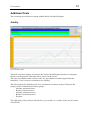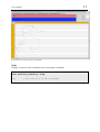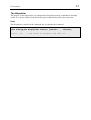
1
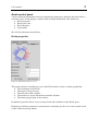
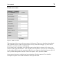
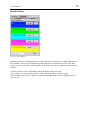
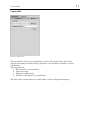
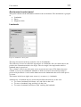
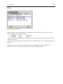
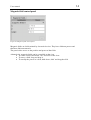
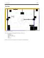
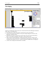
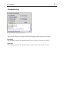
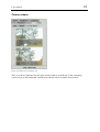
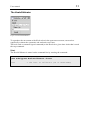
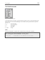
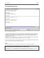
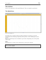
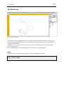
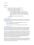
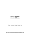
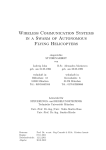
Eukalyptus (Koala Environment Simulator) User Manual Thabo Beeler, University of Applied Sciences, Rapperswil (HSR) 2 User manual Revision History Version 0.1 0.2 0.3 0.4 When 02.06.2004 10.06.2004 12.06.2004 23.06.2004 What Initial version Added screenshots Added screenshots Applied corrections proposed from Jörg Conradt Who Thabo Beeler Thabo Beeler Thabo Beeler Thabo Beeler User manual 3 Table of contents Introduction................................................................................................................................. 4 Terminology................................................................................................................................ 4 Installation .................................................................................................................................. 4 Start ............................................................................................................................................ 4 The simulation ............................................................................................................................ 6 Main screen............................................................................................................................. 6 Control Panel........................................................................................................................... 7 Koala control panel ................................................................................................................. 8 Koala properties .................................................................................................................. 8 Koala error rates .................................................................................................................. 9 Koala shadows................................................................................................................... 10 Log module ....................................................................................................................... 11 Environment control panel..................................................................................................... 12 Landmarks......................................................................................................................... 12 Doors................................................................................................................................. 13 Magnetic field control panel .............................................................................................. 14 The View .............................................................................................................................. 15 The display................................................................................................................................ 16 Connection log ...................................................................................................................... 17 Camera viewer ...................................................................................................................... 18 State view.............................................................................................................................. 19 Additional Tools ....................................................................................................................... 20 Graffity ................................................................................................................................. 20 The Dispatcher ...................................................................................................................... 22 The KoalaCalibrator .............................................................................................................. 23 The KoalaCommander........................................................................................................... 24 The KoalaCommunicator....................................................................................................... 25 The cortices............................................................................................................................... 26 The AlphaCortex ................................................................................................................... 26 The BetaCortex ..................................................................................................................... 27 4 User manual Introduction This document provides the user of the Eukalyptus system with required information. Terminology Some data, such as live video streaming, cannot possibly be provided by the simulator. So it is sometimes essential to distinguish between the real robot and the virtual agent. We will use the following terminology: • Koala agent / agent = refers to the virtual Koala • Koala robot / robot = refers to the real robot • Koala = refers to both Installation Eukalyptus is pure Java, so it runs on every computer with Java VM installed. The version of the virtual machine should be 1.4.2 or higher. Start The user can launch Eukalyptus on the command-line by typing the following command in the Eukalyptus project directory. java eukalyptus.Eukalyptus [-s <map file> | -d <map file> -koala <koala> -lc <localizer> -ld <lm-detection> -vb <vision base>] [-x <x>] [-y <y>] [-orient <orient>] -s map file -d map file -koala -lc -ld -vb -x -y -orient = Start in simulation mode = Path to the .emp file to be used as the map = Start in display mode = Path to the .emp file to be used as the map = IP address of the koala to monitor = IP address of the remote localizer = IP address of the landmark detection = IP address of the vision base = X-coordinate of the initial position of the koala = Y-coordinate of the initial position of the koala = Initial orientation of the koala When all parameters are supplied, Eukalyptus will start immediately. Otherwise it will show a start-up dialog to query the remaining information. User manual Figure 1: Start-up display The application can be started in two different modes: • Simulation • Display Furthermore, you can either load a previously saved .emp file or import a .gif file. For information on how the picture has to be, please refer to the document „User Manual: Map blueprint“. 5 User manual The simulation Main screen Figure 2: The main screen The main screen is divided in four parts: 1) Control panel 2) Koala control panel 3) Environment control panel 4) View 6 User manual Control Panel Figure 3: The control panel The control panel is meant to control the application and the view. • Save = Save the map • Load = Load a new map (.emp file) • Import = Import a new map (.gif/.jpg file) • Zoom = Zoom in/out • Base-ration = The base ratio. 1 pixel in the imported map (image file) corresponds to this ratio in meters. In the above screenshot, 1 pixel corresponds to 0.01 m2 (=1 cm2). • Track = Start/Stop tracking the koala. When on, the Koala agent will be centered at any time. 7 User manual 8 Koala control panel Various different information need to get displayed in tight space; therefore the panel offers a selection of tabs. Each displays a subset of the available information. The subsets are: • Koala properties • Koala error rates • Koala Shadows • Log module We will describe them in detail here. Koala properties Figure 4: The Koala properties screen This panel contains a detailed top-view on the Koala and its sensors. It shows graphically • The orientation of the Koala • The angle of the gyroscope • The direction of the compass • The distance-to-object information from the whiskers • The turning angle (pan) of the cameras In addition it provides direct access to the position and orientation of the Koala agent. Displaying of all these properties is performance consuming. So the view can be turned on/off via the „Start observing“ button. User manual 9 Koala error rates Figure 5: Koala error rates This panel provides access to the error rates of all sensors. They try to simulate the stochastic and systematic errors of the real-world sensors. Every sensor has an upper (+) and a lower deviation (-), which can be set individually. If you want to set a systematic error, like the speed of the Koala is always 10% slower, you need to set the upper deviation to –10% and the lover deviation to +10%. If S is considered to be the original speed, then the speed of the Koala is now Gaussian distributed between [0.9*S, 0.9*S], which corresponds to 0.9*S. This is exactly the –10% speed we wanted. Some sensors have more sophisticated error-functions, like the cameras. For a detailed description of please refer to the document ‘Error specification’. User manual 10 Koala shadows Figure 6: Koala shadows Shadows are views on path integrators. In this panel one can add several path integrators to the simulator. The view will then display the orientation of all shadows on the map. This helps to see how accurate a path integrator is. It serves as well as a comparison base for the cortices. To add a shadow, enter its IP address and port number and push „add“. Once added, you can reset the position of the path integrator or remove it again. The checkbox to the left of a shadow control whether the shadow will be displayed in the view or not. User manual Log module Figure 7: The log view The log module is used to save information over time. The produced log files can be displayed and analyzed in the Graffity application. (See the chapter ‘Graffity’ for more information) The logged data is: • Koala location (x,y,orientation) • Gyroscope angle • Magnetic compass angle • Positions of all shadows (x,y,orientation) The data will be saved n times per second, where n is the configurable frequency. 11 User manual 12 Environment control panel This panel contains all the information related to the environment. The information is grouped in • Landmarks • Doors • Magnetic fields Landmarks Figure 8: Landmarks control panel The drop-down menu at the top contains a list of all landmarks. The fields may be used to control the appearance of a landmark. One can control the id, the position, the orientation and the view angle. The view angle is the angle under which a landmark may be perceived. The (!) button in the lower-left corner serves to prevent user errors. This button becomes enabled, as soon as an established landmark is inside an obstacle and cannot possibly be perceived by the Koala. A click on the button moves the landmark to the next visible spot to it’s front. The buttons in the lower-right corner create (+) or remove (-) a landmark. Alternatively, a landmark may be created and modified interactively on the view. • To create a landmark, hold down ‚ctrl’ and click on the view. • To move a landmark, drag and drop it in the view. • To rotate a landmark, hold down ‚shift’ and drag the landmark. User manual 13 Doors Figure 9: Door control panel Doors cannot be created. They have to be imported in the map file. They have to be color encoded. These colors are the default: • 0x0000FF (blue) closed door • 0x00FF00 (green) open door A door may have an identifier, like „Door room 1 to room 2“ and has a state, which is either „open“ or „closed“. You can select more than one door from the list by holding down ‚shift’ and then toggle them all at once. Alternatively, a door can be selected on the view and toggled by double-clicking on it. Blue doors refer to closed doors, while green doors represent open doors. User manual Magnetic field control panel Figure 10: Magnetic field control panel Magnetic fields are fields emitted by electronic devices. They have different powers and therefore different outreach. The panel offers access to the position and power of the fields. Alternatively, magnetic fields can be controlled on the view. • To create a field, hold down ‚ctrl’ and click on the view. • To move a field, drag and drop it. • To modify the power of a field, hold down ‚shift’ and drag the field. 14 User manual The View Figure 11: The view field The view contains all the graphical elements. These are: - the Koala - landmarks (lm) - magnetic fields (mf) - doors - obstacles Rulers in the metric system provide an intuition of the dimension. 15 User manual 16 The display Figure 12: The display mode Optically, the Eukalyptus display mode does not differ much from the Eukalyptus simulation mode. These are the differences: • The display does, not have the panel to control the error rates of the Koala. • Also the environment editor panels are not present. Map editing has to be done in the Eukalyptus simulation mode. • Instead it has a panel to visualize the network traffic between the stubs and the Koala. This is very useful for debugging. The panel is called connection log. • When connected to the Koala robot, it displays the images of the two cameras on the cameras panel. So the operator may see what the Koala robot perceives. The images are streamed to the display in YUV 4:2:1 format, transformed to RGB 24 bit and displayed. • A state view to display state information is available. User manual Connection log Figure 13: Connection log control panel The user can choose the streams (incoming/outgoing) and the sensors to be logged. Incoming The incoming stream is the data the remote objects (sensors) send to the display. Outgoing The outgoing stream is the data the display sends to the remote objects (sensors). 17 User manual Camera viewer Figure 14: Camera live streaming view This view shows either the left, the right or both cameras of the Koala. Video streaming extensively uses the bandwidth, and therefore should only be enabled when needed. 18 User manual State view Figure 15: Koala state view This view is meant to display state information. It is not interactive. At the moment the battery voltage is the only information displayed. 19 User manual 20 Additional Tools The following tools facilitate working with the Koala and the Eukalyptus. Graffity Figure 16: Main panel This tool is useful to display and analyze the log files the Eukalyptus produces. It interprets the files and displays the contained data as curves on the screen. The same calculations could easily be done in a spreadsheet calculation application like StarOffice, but it is more convenient to use Graffity. The data displayed by Graffity needs to be in different coordinate systems. Therefore the display can be switched between these groups: - Absolute positional errors - Relative positional errors - Absolute orientation errors - Relative Orientation errors - Position The fifth group is the position of the Koala (x,y) over time, or, in other words, the movement of the Koala. 21 User manual Figure 17: Plot of the movement of the Koala Start Graffity is started on the command line by entering the command: java graffity.Graffity <log> log = the log file to be analyzed. 22 User manual The Dispatcher The purpose of this application is to transparently dispatch incoming commands to multiple clients. It is used to control both, the Koala agent and the Koala robot at the same time. Start The Dispatcher is started on the command line by entering the command: java eukalyptus.Dispatcher <host1> [<host2> ... <hostN>] host(1...N) = the hosts to dispatch the data to. 23 User manual The KoalaCalibrator Figure 18: the KoalaCalibrator To reproduce the movement of the Koala robot in the agent most accurate, one needs to empirically evaluate the systematic and stochastic error rates. This tool sends a command (speed command) to the Koala for a given time. After that it sends the stop command. Start The KoalaCalibrator is started on the command line by entering the command: java eukalyptus.KoalaCalibrator <host> host = the host to calibrate (IP or HOST-name) 24 User manual The KoalaCommander Figure 19: The KoalaCommander Useful when one does not have a joystick at hand. It enables a user to control the Koala with the keyboard. It is not convenient though, so one should use the joystick whenever possible. The keys are: • i = move forward • k = move backward • l = turn right • j = turn left • space = stop Start The KoalaCommander is started on the command line by entering the command: java eukalyptus.KoalaCommander <koala_host> koala_host = Hostname or IP address of the koala 25 User manual The KoalaCommunicator Figure 20: The KoalaCommunicator Visualizes network traffic. The user can either choose a command from the pull-down menu or manually type commands and send them to the Koala. The KoalaCommunicator sends only commands available in the pull-down menu, because it needs to know on what socket the command needs to be sent. Alternatively, if the user knows the correct port, he can directly communicate with the socket by prefixing the command with the port number: <port>:<command> Useful to see what happens on the communication layer, and to manually test functions of the Koala without having to start the Eukalyptus display. Start The KoalaCommunicator is started on the command line by entering the command: java eukalyptus.KoalaCommunicator <koala_host> koala_host = Hostname or IP address of the koala User manual 26 The cortices These are first approaches to the map-building task. They are completely experimental. The AlphaCortex Figure 21: The AlphaCortex The alpha cortex is actually not blessed with any intelligence. Its purpose is to test the functionality of the underlying components (SensoryCortex, Cortex, PathIntegrator, optical system). Whenever the Koala perceives a landmark, a spot in the corresponding color will be plotted on the screen. Start The AlphaCortex is started on the command line by entering the command: java cortex.Alpha User manual 27 The BetaCortex Figure 22: The BetaCortex This cortex is a first approach to the idea of the dynamic network construction. Its purpose is to test and demonstrate the idea on a very simple base. It does not correct any errors but only constructs the network. On that way it is, of course, of no practical relevance. Tests showed that it would work in such a perfect world. For more information refer to the document „The cortex – a first approach“. Start The BetaCortex is started on the command line by entering the command: java cortex.Beta