1
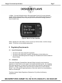
September 27, 2001
Dr. Andrew Rawicz
School of Engineering Science
Simon Fraser University
Burnaby, BC
V5A 1S6
Re: ENSC 340 Functional Specification for the Ranger Electric Bicycle
Dear Dr. Rawicz:
Attached you will find Functional Specification for the Ranger Electric Bicycle, prepared
by Design Outlaws. This document lists the functional requirements for the design and
implementation of our ENSC 340 project.
We are in the process of defining and designing an electrically-assisted bicycle that
maintains a user-settable speed. There are currently no patents for the technology we
propose.
Our design will comply with new regulations for electrically-assisted bicycles, as defined
in April 2001 by Transport Canada. Of all the North American regulations concerning
electric bicycles, these are the most restrictive, and appear as requirements in this
document.
We have included a test plan for correct operation and compliance with regulations and
other requirements as defined in the functional specification.
Rhiannon Coppin, Eric Hennessey, Samuel Hu, and Eric Keung are the Design Outlaws.
Please feel free to contact us with any questions or concerns through
[email protected]
Sincerely,
Rhiannon Coppin
Project Manager
Design Outlaws
Enclosure: Functional Specification for the Ranger Electric Bicycle
FUNCTIONAL SPECIFICATION FOR THE
RANGER ELECTRIC BICYCLE
Project Team
Design Outlaws
Rhiannon Coppin
Eric Hennessey
Samuel Hu
Eric Keung
Contact Personnel
Rhiannon Coppin
[email protected]
Submitted to
Date Issued
Revision
Dr. Andrew Rawicz, Steve Whitmore
School of Engineering Science
Simon Fraser University
September 27, 2001
1.0
Project Proposal
Executive Summary
As city streets become more congested, fuel prices continue to rise, and air pollution
increases in severity, people are demanding a more convenient, inexpensive, and
healthy transportation alternative. Design Outlaws have determined that one of the most
promising alternatives for many lifestyles is the electric bicycle. Therefore, our mission is
to make the electric bicycle a more attractive commuting option. After surveying the
current state of electric bicycle technology, we concluded that the following features are
urgently required in order to increase public acceptance of electric bicycles:
1) The electrical motor needs to take effect smoothly, providing a gradual and naturalfeeling acceleration.
2) The user must be able to preset their target speed, and have the motor compensate
for pedaling deficiencies.
3) The motor must turn off when the bicycle exceeds the selected speed, past which
the user must power the bicycle.
Features that have already been developed and are also desired in the Ranger are:
1)
2)
3)
4)
Battery rechargeable through interface to an AC wall outlet
Speedometer and odometer
Smooth motor transmission
Limited top speed, to comply with non-motorized vehicle regulations
The prototype, which we have named the Ranger will incorporate all the above features,
and will be completed in December 2001.
ii
Project Proposal
Table of Contents
EXECUTIVE SUMMARY..................................................................................................................II
1
INTRODUCTION .....................................................................................................................1
1.1
1.2
1.3
SCOPE ..................................................................................................................................1
REFERENCED DOCUMENTS ....................................................................................................1
INTENDED AUDIENCE..............................................................................................................2
2
SYSTEM OVERVIEW ..............................................................................................................3
3
SYSTEM REQUIREMENTS ....................................................................................................4
3.1 PHYSICAL REQUIREMENTS .....................................................................................................4
3.2 SYSTEM CAPABILITIES AND PHYSICAL FEATURES ....................................................................4
3.2.1 General .......................................................................................................................4
3.2.2 Operating Conditions ..................................................................................................5
3.2.3 Performance................................................................................................................5
3.2.4 Safety ..........................................................................................................................5
3.2.5 Reliability.....................................................................................................................5
4
USER INTERFACE REQUIREMENTS ...................................................................................6
4.1
4.2
5
REGULATORY REQUIREMENTS..........................................................................................7
5.1
5.2
6
INTERFACE INPUTS.................................................................................................................6
INTERFACE OUTPUTS .............................................................................................................6
SPECIFIC STANDARDS ............................................................................................................7
GUIDELINES ...........................................................................................................................7
TEST PROCEDURE................................................................................................................8
6.1
6.2
6.3
6.4
6.5
6.6
6.7
ACCELERATION TO HALF SPEED, MOTOR ONLY .........................................................................9
ACCELERATION TO FULL SPEED, MOTOR ONLY .........................................................................9
ACCELERATION TO HALF SPEED, MOTOR AND MANUAL..............................................................9
ACCELERATION TO FULL SPEED, MOTOR AND MANUAL ..............................................................9
MOTOR SHUT-OFF ON BRAKING ...............................................................................................9
MOTOR SHUT-OFF ON DISENGAGE SWITCH ............................................................................10
CHANGE PRE-SETTABLE SPEED WHILE IN MOTION ..................................................................10
7
DOCUMENTATION AND USER MANUAL ..........................................................................10
8
FUTURE DEVELOPMENTS..................................................................................................11
9
CONCLUSION .......................................................................................................................11
iii
Ranger Functional Specification
Page 1
1 Introduction
The Ranger is an electric bicycle, incorporating a rechargeable electric power source, a
variable torque and variable speed electric motor, and associated control mechanisms.
The Ranger's unique features include a pre-settable speed control, and smooth
acceleration to the target speed in the presence or absence of external pedaling. The
Ranger’s control system will allow the user to pedal as with a regular bicycle, and will
determine the level of motorized output necessary to achieve and maintain the desired
speed that the user selects through a digital interface. The Ranger will function on
various terrains and under severe conditions. Finally, the Ranger will incorporate all
safety features as set out by various state and federal legislation, in addition to the
safety features deemed necessary by Design Outlaws.
1.1
Scope
This document describes the functional requirements for a prototype of the Ranger
commuter bicycle. This prototype will act as a proof-of-concept device and will allow for
further feature developments, which are briefly documented in the final section. The
requirements we have set forth for the prototype, along with the consideration of future
requirements, both motivate the design of the Ranger.
1.2
Referenced Documents
[1] Proposal for Design and Implementation of Electric Bicycle Technologies.
Design Outlaws, Rev 2.0, September 18, 2001.
[2] MOTOR VEHICLE SAFETY ACT: Regulations Amending the Motor Vehicle
Safety Regulations (Expiry Dates for Sections 108, 131 and 206). Canada
Gazette Part II, Vol. 135, No. 8. 2001-04-11. Registration SOR/2001-116, 29
March, 2001.
[3] Bordonaro (Senator Mountjoy, coauthor), An act to amend Sections 406 and
12804.9 of, and to add Section 24016 to, the Vehicle Code, relating to vehicles.
TOPIC: Motorized bicycle: electric motor: definition. California Vehicle Code,
Measure A.B. No 1501, Chaptered (Chapter 804) 10/13/95.
[4] Thibaudeau, Wood, Haugen, and Prince (Senators), Senate Bill 5968, Chapter
328, Laws of 1997: Electric-assisted bicycles. State of Washington Laws.
Effective Date, 7/27/97.
1
Ranger Functional Specification
1.3
Page 2
Intended Audience
This document is intended for designers, design engineers, and managers to use in the
design process of the development of the Ranger.
The Project Manager will use this document as a guide in timeline development, goalsetting, and test acceptance.
The marketing department may also use this document to secure funding when an
interested investor requires more information.
2
Ranger Functional Specification
Page 3
2 System Overview
Error! Reference source not found.1 illustrates the overall system of the Ranger
bicycle.
Figure 1: Electric Bicycle System Diagram
This device incorporates an electric motor, operating with a rechargeable battery source,
into a regular adult bicycle. The user will be able to view system parameters and
statistics on a LCD screen mounted on the handlebars.
The user will be able to select a target motor-assisted commuting speed between 030km/hr. Then, if the user engages the motor with a separate switch and begins
pedaling, the motor will engage to accelerate the bicycle to that target speed. The
acceleration will be gradual, smooth, and feel natural and safe to the user. As the user
3
Ranger Functional Specification
Page 4
increases the amount of pedaling, the control system will reduce the motor output in
order to maintain the target speed.
When travelling at speeds greater that the target speed, (for example, when going
downhill), the motor will disengage and the motor will reengage once the speed drops a
predetermined amount below the target speed. When, for example, the user is tired and
reduces pedaling, the control system will allow for a specific drop in speed (e.g. 5km/h)
before triggering to motor to reengage.
The control system will sense the application of either brake, and the motor will turn off
when the brakes are applied.
3 System Requirements
3.1
Physical Requirements
The Ranger bicycle will be designed and implemented on a standard road bike that we
hope to obtain via sponsorships. Major components that must be included are as
follows:
Drive System
Electrically-powered motor, < 500W output
Rechargeable battery pack
Control System
Microcontroller
Alkaline battery
Speed sensor
Brake sensor
Battery Charge Sensor
Display System
Liquid Crystal Display
Input push buttons
Motor power switch
3.2
System Capabilities and Physical Features
3.2.1
•
•
•
General
Overall weight (including bicycle weight) not exceeding 16 kg
Motor, battery, and control system are positioned such that they do not interfere
with pedaling
Battery completely rechargeable in 8 hours
4
Ranger Functional Specification
3.2.2
•
•
•
•
3.2.3
•
•
3.2.4
Page 5
Operating Conditions
Waterproof under severe rain/puddle conditions.
Resistant to failure from caking/drying of mud on frame and frame components
The system will operate in ambient temperatures from –5oC to 35 oC.
The system will survive frost and dew.
Performance
Top speed of 30 km/hr on flat terrain or 15 km/hr up a 7% grade
Range of 30 km with full motor output on flat terrain
Safety
The following is a list of features that we will include thereby maximizing the safety of the
Ranger:
Drive System
The maximum speed while the motor is engaged is 30 km/hr
The motor will be housed in a heat resistant, removable casing.
Appropriate warning labels will also be included
The motor will be mounted such that all moving parts are protected
from the user
Electrical wiring compliant with appropriate Canadian and US
standards
Control System
Motor will engage only if the following conditions are satisfied
• Motor switch is in on position
• Brakes are not being applied
• Bicycle is travelling at a speed of 3 km/hr
Display System
Display will be mounted such that it is viewable under various
lighting conditions and from different viewing angles
3.2.5
Reliability
The Ranger will meet the following reliability requirements:
•
•
•
Battery charge indicator will be valid to ±5%
Velocity measurement will be valid to ±2 km/h
Along flat terrain, motor will maintain speed at ±2 km/h the preset value under
condition of constant user-input
5
Ranger Functional Specification
Page 6
4 User Interface Requirements
4.1
Interface Inputs
The following is a list of buttons and sensors that will allow the user to provide the
system with inputs:
•
•
•
•
•
On/off button to control LCD
On/off switch to control motor
Mode button to toggle the current display on the LCD
Up/down button to input and/or reset information
Sensor to detect application of brake
For the prototype, we the user will be able to increase or decrease the target speed in
increments of 5km/h, using the up/down button in the list above.
4.2
Interface Outputs
The following information will be displayed to the user via the liquid crystal display:
•
•
•
•
•
•
Current speed of travel (in km/h, to one decimal place)
Target speed (in increments of 5km/h)
Distance traveled, (in km, to one decimal place)
Time traveled, (in hour and minutes)
Average trip speed (in km/h, to unit place)
Current charge of battery
This information will be presented to the user through the use of two mode screens.
Figure 2 and Figure 3 are mockups of the LCD inputs, and outputs for the two display
modes.
Figure 2: Mode 1 of User Interface
6
Ranger Functional Specification
Page 7
In Mode 1, the top left-hand number is the target speed (in km/h), the top right-hand
number is the current speed (in km/h), and the bottom vertical lines show the range of
battery charge possible (2 lines in top row) and the current state of charge (series of
lines in bottom row).
Figure 3: Mode 2 of User Interface
Mode 2 displays the total distance for the current trip, the time taken, and the average
speed. These are not user-settable parameters.
5 Regulatory Requirements
5.1
Specific Standards
•
•
•
5.2
The device will comply with CSA regulations.
The device will comply with Transport Canada Motor Vehicle Safety Act
The device’s electrical system will comply with Canadian and American National
Electric Codes.
Guidelines
The current Transport Canada Motor Vehicles Safety Act has the most restrictive
legislation in North America, with regard to electrically-assisted bicycles. By complying
with these regulations, our design will comply with the less-restrictive state-specific US
legislation. Design Outlaws aims to have the device classed as a “power-assisted
bicycle”, due to the specific legal implications of this class, which is not considered the
same as a motorcycle.
The Motor Vehicle Safety Regulations (Subsection 2(1)) define the following
requirements:
7
Ranger Functional Specification
Page 8
“power-assisted bicycle” means a vehicle that:
a) has steering handlebars and is equipped with pedals,
b) is designed to travel on not more than three wheels in contact with the ground,
c) is capable of being propelled by muscular power,
d) has an electric motor only, which has the following characteristics, namely:
i)
it has a continuous power output rating, measured at the shaft of the motor,
of 500W or less,
ii)
if it is engaged by the use of muscular power, power assistance immediately
ceases when the muscular power ceases,
iii)
if it is engaged by the use of an accelerator controller, power assistance
immediately ceases when the brakes are applied, and
iv)
it is incapable of providing further assistance when the bicycle attains a
speed of 32km/h on level ground.
e) bear a label that is permanently affixed by the manufacturer and appears in a
conspicuous location stating, in both official languages, that the vehicle is a powerassisted bicycle as defined in this subsection, and
f) has one of the following safety features,
i)
an enabling mechanism to turn the electric motor on and off that is separate
from the accelerator controller and fitted in such a manner that it is operable
by the driver, or
ii)
a mechanism that prevents the motor from being engaged before the bicycle
attains a speed of 3km/h.
Further requirements, from California and Washington State laws are:
•
•
The device will operate in such a manner so that the electric motor is disengaged or
ceases to function when the brakes are applied, or operate in a manner such that the
motor is engaged through a switch or mechanism that, when released, will cause the
electric motor to disengage or cease to function.
The device will comply with the equipment and manufacturing requirements for
bicycles adopted by the Consumer Product Safety Commission (16 C.F.R. 1512.1, et
seq).
6 Test Procedure
The Ranger bicycles must completely and successfully handle the following scenarios,
given that the battery is charged and connected to the bicycle, and that the motor
engage switch is in the "on" position. This of course, is not a complete list of all test
procedures that will be followed. Additional testing will be done during system
development, and a full safety procedure, including testing with the bike on a stationary
rig, will be verified before any road tests are attempted.
8
Ranger Functional Specification
Page 9
6.1
a)
b)
c)
d)
Acceleration to half speed, motor only
Set assist speed to 15 km/h.
Manually increase speed to 3 km/h.
At 3 km/h, motor should engage and provide a smooth acceleration up to 15 km/h.
Motor will maintain speed of 15 km/h both along a flat road, and up a 7% grade.
6.2
a)
b)
c)
d)
Acceleration to full speed, motor only
Set assist speed to 30 km/h.
Manually increase speed to 3 km/h.
At 3 km/h, motor should engage and provide a smooth acceleration up to 30 km/h.
Motor will maintain speed of 30 km/h along a flat road.
6.3 Acceleration to half speed, motor and manual
a) Set assist speed to 15 km/h.
b) Pedal at comfortable rate.
c) At 3 km/h, motor should engage and smoothly assist bicycle up to 15 km/h, while
pedaling.
d) Continue pedaling to 20 km/h; motor should have disengaged past 15km/h. Stop
pedaling, and motor should smoothly reengage when speed again reaches below
15 km/h.
6.4 Acceleration to full speed, motor and manual
a) Set assist speed to 30 km/h.
b) Pedal at comfortable rate.
c) At 3 km/h, motor should engage and smoothly assist bicycle up to 30 km/h, while
pedaling
d) Pedal to 35 km/h and then stop pedaling; motor should have disengaged at 30
km/h. As speed dips below 30km/h, motor should smoothly reengage to maintain a
speed of 30 km/h
6.5
a)
b)
c)
d)
e)
f)
g)
Motor shut-off on braking
Set assist speed to 30 km/h.
Manually increase speed to 3 km/h.
At 3 km/h, motor should engage and begin smoothly accelerating bicycle.
At 15 km/h, pull brakes; motor should immediately disengage.
Release brakes; motor should smoothly reengage, acceleratin. up to 30 km/h.
At 30 km/h, pull brakes; motor should immediately disengage.
Release brakes; motor should smoothly reengage, accelerating up to 30 km/h.
9
Ranger Functional Specification
Page 10
6.6
a)
b)
c)
d)
Motor shut-off on disengage switch
Set assist speed to 30 km/h.
Manually increase speed to 3 km/h.
At 3 km/h, motor should engage and begin smoothly accelerating bicycle.
At 15 km/h, move motor engage switch to off position; motor should immediately
disengage.
e) Move switch to on position; motor should smoothly reengage, accelerating up to 30
km/h.
f) At 5 km/h, move motor engage switch to off position; motor should immediately
disengage.
g) Move switch to on position; motor should smoothly reengage, accelerating up to 30
km/h.
6.7 Change pre-settable speed while in motion
a) Start with target speed set to 0km/h.
b) Begin pedaling, past 3km/h; motor should not engage.
c) Continue pedaling at speed above 3km/h but below 5km/h. Increase target speed to
5km/h through Mode 1 of User Interface (this is accomplished with one button
push).
d) Motor should engage as new speed is selected, similar to the fashion in which
treadmill speed increases are selected and applied (i.e. without further input).
e) Repeat test for remaining speed increments.
7 Documentation and User Manual
•
•
•
•
•
•
Documentation for the production version of this device will consist of a ten-page
document, including care and operating instructions. This document will be
accompanied by a province or state-specific four-page pamphlet of current laws,
regulations, and restrictions for operation of the device.
The user manual will be written for an audience with little or no bicycle knowledge.
Parts of the bicycle and system will be named, diagrammed, and explained.
The operations pamphlet will include basic road regulations, since the user is not
required to hold a driver's license.
Minimal user training should be necessary for this device.
No guided user training should be necessary for experienced cyclists to safely
operate this device.
Users of the proof-of-concept prototype will be instructed and supervised by the
product developers during demonstration sessions, and assume all liabilities.
10
Ranger Functional Specification
Page 11
8 Future Developments
Future designs, implementations, and productions of this device will satisfy some or all of
the following requirements:
•
•
•
Selection of unit base on display (km or miles)
Battery recharging from dual motor-generator, when motor not in use.
Interface to solar-panel battery recharging
9 Conclusion
The requirements set out in this document specify the minimal features required in a
successful Ranger prototype. Modifications will be made by Design Outlaws to the user
interface, performance criteria, and reliability restrictions, as necessary and as additional
needs surface during product development. At the same time, the safety regulations
and target functionality are static requirements. We at Design Outlaws feel that design
and implementation of the functionality set out in this document is achievable by
December 2001, and will result in a successful product for our team and for outside
parties, as defined in our initial proposal.
11


![報告書 - [SCOPE] 一般財団法人 港湾空港総合技術センター](http://vs1.manualzilla.com/store/data/006652679_2-300b96f8edd315618c4b0e502c3b9187-150x150.png)