1
USER’S MANUAL
CONTENTS
User’s Manual ____________________________________________________________________ - 1 Contents_________________________________________________________________________ - 2 Notice ___________________________________________________________________________ - 3 Introduction ______________________________________________________________________ - 4 Aberdeen Contact Information ______________________________________________________ - 5 5-Year Warranty Terms and Conditions _______________________________________________ - 5 Mission Statement ________________________________________________________________ - 6 Company Background _____________________________________________________________ - 6 Goals ___________________________________________________________________________ - 7 The Aberdeen Advantage___________________________________________________________ - 7 Aberdeen Leads Industry with 5-Year Warranty ________________________________________ - 8 Custom Server Solutions Provider ___________________________________________________ - 8 References _______________________________________________________________________ - 9 Reviews and Awards _____________________________________________________________ - 10 Previous Comments from the Experts _______________________________________________ - 10 APPENDIX - A AberNAS 106 _______________________________________________________ - 11 Aberdeen AberNAS 106 Spec Sheet _________________________________________________ - 12 AberNAS 106 Disk Placement Chart _________________________________________________ - 14 APPENDIX - B AberNAS 110/116 ___________________________________________________ - 15 Aberdeen AberNAS 110/116 Spec Sheet _____________________________________________ - 16 AberNAS 110/116 Disk Placement Chart _____________________________________________ - 18 APPENDIX - C AberNAS 221 _______________________________________________________ - 19 Aberdeen AberNAS 221 Spec Sheet _________________________________________________ - 20 AberNAS 221 Disk Placement Chart _________________________________________________ - 22 APPENDIX - D AberNAS 231/232 ___________________________________________________ - 23 Aberdeen AberNAS 231/232 Spec Sheet _____________________________________________ - 24 AberNAS 231/232 Disk Placement Chart _____________________________________________ - 26 APPENDIX - E Microsoft Windows Storage Server 2003 ________________________________ - 27 AberNAS by Aberdeen EASY SETUP ________________________________________________ - 28 APPENDIX - F 3ware Escalade Controller ____________________________________________ - 29 3DM Disk Management Utility ______________________________________________________ - 30 -
-2-
NOTICE
No part of this manual, including the products and software described in it, may be reproduced, transmitted,
transcribed, stored in a retrieval system, or translated into any language in any form or by any means, except
documentation kept by the purchaser for backup purposes, without the express written permission of ABERDEEN
LLC. ("ABERDEEN").
ABERDEEN PROVIDES THIS MANUAL "AS IS" WITHOUT WARRANTY OF ANY KIND, EITHER EXPRESS OR IMPLIED,
INCLUDING BUT NOT LIMITED TO THE IMPLIED WARRANTIES OR CONDITIONS OF MERCHANTABILITY OR FITNESS
FOR A PARTICULAR PURPOSE. IN NO EVENT SHALL ABERDEEN, ITS DIRECTORS, OFFICERS, EMPLOYEES OR
AGENTS BE LIABLE FOR ANY INDIRECT, SPECIAL, INCIDENTAL, OR CONSEQUENTIAL DAMAGES (INCLUDING
DAMAGES FOR LOSS OF PROFITS, LOSS OF BUSINESS, LOSS OF USE OR DATA, INTERRUPTION OF BUSINESS
AND THE LIKE), EVEN IF ABERDEEN HAS BEEN ADVISED OF THE POSSIBILITY OF SUCH DAMAGES ARISING FROM
ANY DEFECT OR ERROR IN THIS MANUAL OR PRODUCT.
Product warranty or service will not be extended if: (1) the product is repaired, modified or altered, unless such
repair, modification of alteration is authorized in writing by ABERDEEN; or (2) the serial number of the product is
defaced or missing.
Products and corporate names appearing in this manual may or may not be registered trademarks or copyrights of
their respective companies, and are used only for identification or explanation and to the owners' benefit, without
intent to infringe.
•
•
•
•
•
•
Aberdeen, Stirling, AberNAS, Backup Monster, TeraBuster, TeraStorus, and XDAS are registered
trademarks of Aberdeen LLC.
Intel, Pentium, and Xeon are registered trademarks of Intel Corporation.
3ware and Escalade are registered trademarks of Applied Micro Circuits Corporation.
Microsoft, Windows, and Windows NT are registered trademarks of Microsoft Corporation.
Adobe and Acrobat are registered trademarks of Adobe Systems Incorporated.
Adaptec is a registered trademark of Adaptec Inc.
For previous or updated manuals, BIOS, drivers, or product release information, contact ABERDEEN at
http://www.Aberdeeninc.com or through any of the means indicated on the following pages.
SPECIFICATIONS AND INFORMATION CONTAINED IN THIS MANUAL ARE FURNISHED FOR INFORMATIONAL USE
ONLY, AND ARE SUBJECT TO CHANGE AT ANY TIME WITHOUT NOTICE, AND SHOULD NOT BE CONSTRUED AS A
COMMITMENT BY ABERDEEN. ABERDEEN ASSUMES NO RESPONSIBILITY OR LIABILITY FOR ANY ERRORS OR
INACCURACIES THAT MAY APPEAR IN THIS MANUAL, INCLUDING THE PRODUCTS AND SOFTWARE DESCRIBED IN
IT.
Copyright © 2004 ABERDEEN LLC. All Rights Reserved.
-3-
INTRODUCTION
Aberdeen LLC, the Custom Server Solution Provider, has provided an excellent
selection of quality custom computing solutions to the IT professional for more than
a decade. As an innovator of storage solutions Aberdeen has become a one-stop
solution source for the IT Professional.
The computer industry is a continuously evolving marketplace. With a clear vision
of the future, Aberdeen has become a trend setter via its vast technical experience
and industry foresight. Aberdeen is a pioneer in providing customizable rack
mounted servers, backup solutions and scalable NAS storage appliances.
Aberdeen Rackmount Storage Server applicable models.
•
Aberdeen AberNAS 106 - 1U NAS Appliance
•
Aberdeen AberNAS 110 - 1U NAS Appliance
•
Aberdeen AberNAS 231 - 2U NAS Appliance
•
Aberdeen XDAS – Scalable Storage and NAS
As an industry leader, Aberdeen not only reduces cost of ownership by offering the
longest warranty in the industry, but also has demonstrated better performance
and has proven to provide a better ROI than the competition in head-to-head
comparisons
-4-
ABERDEEN CONTACT INFORMATION
Aberdeen understands that service does not stop once a product ships. We
sincerely hope there will never be a situation in which a problem arises; however,
should there be a need for service, Aberdeen will be there to provide the prompt,
courteous, and efficient service expected.
Headquarters
Address:
Telephone:
Fax:
Email:
WWW:
9130 Norwalk Blvd. Santa Fe Springs, California 90670
562-699-6998
562-695-5570
[email protected]
www.Aberdeeninc.com
Customer Support
Hours:
Monday - Friday, 8am – 5pm PST
Telephone:
562-699-6998 ext. 152
Email:
[email protected]
Technical Support / RMA
Hours:
Monday - Friday, 8am – 5pm PST
Telephone:
562-699-6998 ext. 326
Email:
[email protected]
5-YEAR WARRANTY TERMS AND CONDITIONS
Aberdeen provides an industry leading 5-Year Warranty on any of its fully
configured rackmount servers. All Aberdeen fully configured rackmount solutions
are warranted to be free of defects in materials for a period of five years from date
of shipment or the lifetime of the product to be free of workmanship
defects. A fully configured rackmount system is defined as a system,
which in a single purchase includes the rackmount chassis,
motherboard, processor(s) with appropriate cooling equipment,
memory and hard disk drive(s) all assembled. This warranty does
not cover any abuse, misuse or modification of products. We reserve
the right to repair or replace the defective product under warranty as we see
appropriate. We do not warrant uninterrupted or error-free operation of a product.
We do not warrant that any product that you acquire will meet your individual
requirements
"Aberdeen’s warranty is ‘REAL’ and their response is immediate!"
- Customer testimonial; Mr. Tawfik Daoud, Maximus Inc.
-5-
MISSION STATEMENT
The Straight Talk People. - The primary business focus for Aberdeen is to be the IT
professional's preeminent resource for complete network solutions, while remaining
dedicated to building and maintaining excellent service and support relationships
with its clientele.
COMPANY BACKGROUND
Founded in 1991, Aberdeen LLC is a leading direct marketer
of rackmount servers, storage solutions, computers and
computer hardware. Voted among The Direct 100 vendors by
PC Computing magazine, Aberdeen designs, manufactures
and customizes award-winning Aberdeen brand computer
systems, Stirling rackmount servers, AberNAS storage
appliances and backup storage servers. Aberdeen LLC
provides assistance to its vast customer base in the planning,
budgeting and implementation of complete network solutions
including High-Performance Computing and NAS/SAN
deployment within existing IT environments. For product
sales, service or company information, contact Aberdeen at
800-552-6868, by fax at 562-695-5570 or visit
www.aberdeeninc.com.
-6-
GOALS
To provide rack mounted server, data storage, and network solutions to the
business, government, education and telecommunication sectors.
To continually offer a comprehensive selection of cutting-edge computer hardware
components and be the single source for the most reliable and the best valued
backend server networking solutions in the market.
To exceed its clients’ expectations through dedicated one-on-one service,
unequalled attention to detail, and custom solutions designed to overcome
networking obstacles.
THE ABERDEEN ADVANTAGE
Aberdeen's consummate professional and highly experienced sales, management
and technical teams are key elements in its ability to provide the finest complete
network solutions and service available in the marketplace.
With unparalleled experience in the industry, Aberdeen has accumulated the
expertise to design and custom configure any network ranging from a couple of
workstations to a complete SAN/NAS network environment.
Aberdeen's ability to provide the best service and hardware availability is enhanced
by its certifications and partnerships with the recognized leaders in the computer
industry.
Company Certifications include:
- Microsoft Certified Partner
- Intel Premier Provider
Staff certifications and qualifications:
- Microsoft Certified Professional
- Microsoft Certified Systems Engineer
- Intel Certified Solution Consultant
- Intel Certified Integration Specialist
- Novell Unix and Linux Professionals
-7-
ABERDEEN LEADS INDUSTRY WITH 5-YEAR WARRANTY
Aberdeen is pleased to provide an industry leading 5-Year Warranty
on any of its fully configured rackmount servers. Whether you
select one of the pre-configured Stirling servers or custom design a
complete server for yourself, it will be warranted to be free of
defects in materials for a period of five years from the date of
shipment and for the lifetime of the product to be free of
workmanship defects.
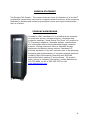
CUSTOM SERVER SOLUTIONS PROVIDER
Aberdeen LLC has provided personal and corporate customers quality custom
computing solutions for more than a decade. Customizable Stirling rack mounted
servers, backup solutions and AberNAS storage appliances not only offer a longer
warranty and demonstrate better performance, but have proven to provide a better
ROI than the competition in head-to-head comparisons. Aberdeen offers a
comprehensive product line for the Gaming Enthusiast to the IT Professional.
•
•
•
•
•
•
•
•
•
Fully Customizable Rackmounts, Servers, Chassis and Systems
Full Network Solutions and Rackmount Server Cabinet Models
NAS/SAN Mass Storage Solutions Units and Appliances
RAID protected Disaster Recovery and Backup Servers
Governmental, Educational and Corporate Workstations
Complete Server Solutions for Microsoft, Unix and Linux platforms
Industrial PC Components; Data Acquisition, SBCs and Backplanes
Hand Held & Modular Hard Drive Duplication
Comprehensive line of PC Hardware
-8-
REFERENCES
Over the years Aberdeen LLC has been privileged to work with companies that
share similar expectations and professional goals to its own such as unmatched
customer service, personal and professional integrity, honest communication and
the commitment to forming long-term partnerships.
The innovative Stirling “Backup Monster” storage server impressed Tawfik Daoud,
senior system engineer of Maximus Inc. enough to praise Aberdeen in a recent
letter. Mr. Daoud mentioned that he chose Aberdeen since the “Backup Monster”
costs considerably less than the closest competitor and was “amazed” with the ease
of implementation and performance. Mr. Daoud goes on to write in his testimonial.
"The "Backup Monster" is one step ahead in the backup industry and what
I like most is that Aberdeen is backing it up."
The Stirling S21 Server appealed to David Featherstone, a network administrator
for Timber Products, a company of 1,500 employees, who told PC Magazine how
happy he is with the Stirling brand server and that he plans to purchase more in
the future.
"Over the years, I've tried everything," Mr. Featherstone says. "I have
built my own servers, or bought them from major vendors, but I really like
these. The value you get for your money is impressive."
Satisfied clients are the best reference for Aberdeen. Below includes a sample of
some of the world-class companies whose rack mounted server expectations have
been exceeded by Aberdeen to the point that they have become frequent repeat
customers.
Adventists
Intel
Ohio State University
University of Michigan
Boeing
Lockheed
Paramount Pictures
University of Washington
Computer Sciences Corp
Microsoft
Penn State University
US Army
Cornell University
Motorola
Raytheon
US Navy
Central Intelligence Agency
Northrup Grumann
Stanford University
Vanderbilt University
Dow Chemical
Novartis Pharmaceuticals
Timber Products
Verizon
IBM
Oak Ridge National Lab
UC Lawrence Berkeley Lab
Virgin Entertainment
-9-
REVIEWS AND AWARDS
Throughout the years Aberdeen LLC has received praise and critical acclaim for
custom built servers and desktop systems. Take a look at these recent comments
about Aberdeen Stirling Servers from - PC Magazine.
“The Stirling S17 Merits an Honorable Mention” - PC Magazine 2003
“The least expensive Intel-based server in our roundup, the Aberdeen Stirling S17
offers a lot of power and scalability for the money.” - PC Magazine 2003
“We were impressed with the Stirling S17's performance; it generally led the pack
in test results” - PC Magazine 2003
“Astonishingly Low Price. Inexpensive, Hardworking Server the Aberdeen Stirling
S21 is a good choice." - PC Magazine 2002
“With an Unrivaled five-year warranty … (the Stirling S21) offers comparable
components and performance (to IBM)." - PC Magazine 2002
PREVIOUS COMMENTS FROM THE EXPERTS
"The Claymore D90G is the fastest PC we've seen so far." - Maximum PC 2001
“There's No Mystery Here- This One's a Beast … Aberdeen’s Loch Ness machine is a
tower of power.” – Loch Ness D80G - Maximum PC 2001
“Aberdeen shows us what a real gaming system should be all about with its latest
computer.” – Loch Ness D45G - PC Gamer Editors' Choice 1999
- 10 -
APPENDIX - A
ABERNAS 106
- 11 -
ABERDEEN ABERNAS 106 SPEC SHEET
MAXIMIZE:
•
•
•
•
•
•
•
Network Storage Capacity
Hardware Redundancy and Reliability
Network Performance
Management Simplicity
Scalability
Cost / GB Ratio
Peace of Mind with a 5-Year Warranty
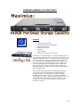
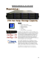
Inevitably you will need to replace or increase the capacity of your
network storage, application server storage or back-up storage. The
AberNAS by Aberdeen allows you to enjoy the benefits of a featurerich, high-performance network attached storage without the high
cost of ownership. The AberNAS by Aberdeen is the solution of
choice to provide the power and features to support today’s most
dynamic and demanding network infrastructures. Packed with
server management, security and mission-critical features the
AberNAS by Aberdeen provides the best priced entry NAS appliance
with the AberNAS 106.
As the ultimate reliable NAS server, the AberNAS 106 stresses
value, speed, ease of management and dependable storage..
Configured with four ultra fast SATA drives, the cost efficient
AberNAS 106 can provide the best valued small business NAS
storage appliance solution. Yielding the best storage capacity, the a
1U AberNAS 106 storage appliance allows for a RAID 0, 1, or 5
storage environment thus offering flexibility and speed without
sacrificing on security.
- 12 -
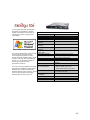
For the system/storage administrator,
managing an organization’s growing
wealth of information has become an
increasingly complex, high pressure
undertaking.
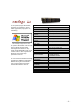
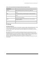
MODEL
FORM FACTOR
BASE CAPACITY
PROTOCOL SUPPORT
MAX RAID 0
CAPACITY
MAX RAID 1
CAPACITY
MAX RAID 5
CAPACITY
Microsoft® Storage Server 2003.
MAX SINGLE
ARRAY SIZE
The system administrator must take into
OPERATING SYSTEM
account rapidly changing storage
PROCESSOR
technologies. While there are many
storage solutions available today, not all
MEMORY
solutions scale well with organizational
growth, nor are all equally capable of
RAID ENVIRONMENT
delivering cost-effective high
performance solutions.
HOT SWAP
The new and enhanced data and storage
management capabilities of Microsoft®
Windows Server 2003 and Microsoft
Windows Storage Server 2003 are critical
tools in helping system and storage
administrators do more with less.
INCLUDED
OS / DATA DRIVES
ETHERNET
ETHERNET LOAD
BALANCING
POWER SUPPLY
RAILS
WARRANTY
SPECIFICATIONS
AberNAS 106
1U, 19" Rackmount
640 Gigabytes
CIFS, NFS, NCP, HTTP and FTP
640 Gigabytes
320 Gigabytes
480 Gigabytes
640 Gigabytes
Windows® Storage Server 2003
Intel Pentium 4 2.4GHz at 533MHz
Front Side Bus 512K Cache
512MB ECC Reg. DDR SDRAM
Integrated Marvell 4 port RAID
controller
4 Bays
4 x 160GB SATA 8MB Cache
- 8GB OS Partition per Drive
- 152GB DATA Partition per Drive
Dual Intel Gigabit controller
2 x 10/100/1000 ports
Load Balancing, Teaming and Failover
350w
Included
5-Year Limited
- 13 -
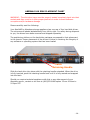
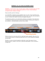
ABERNAS 106 DISK PLACEMENT CHART
WARNING – The disk drive trays must be properly seated completely back into their
sockets and they must be in their proper positions in order to avoid software
corruption and/or hardware damage.
Please carefully read the following:
Your AberNAS by Aberdeen storage appliance has one row of four hard disk drives.
The columns are labeled alphabetically from left to right. For safety during shipment
to you, the drives have been removed and shipped separately.
The positioning stickers on the hard drive packages correspond to their placement
in the chassis. Proper placement of the drives is critical in retaining the integrity of
any software or operating system that has been loaded.
Column A
Row 1
A1
Column B
B1
Column C
C1
Column D
D1
Latch
Retaining Handle
Slide the hard drive into place with the retaining handle extended. When the drive
is fully inserted, push the retaining handle back until it is fully seated and snapped
into the latch.
Should you require technical assistance with this or any other aspect of your
Aberdeen server, contact us toll free at (800)552-6868 option 2 from 8:00am to
5:00pm PST.
- 14 -
APPENDIX - B
ABERNAS 110/116
- 15 -
ABERDEEN ABERNAS 110/116 SPEC SHEET
MAXIMIZE:
•
•
•
•
•
•
•
Network Storage Capacity
Hardware Redundancy and Reliability
Network Performance
Management Simplicity
Scalability
Cost / GB Ratio
Peace of Mind with a 5-Year Warranty
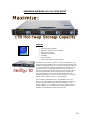
Inevitably you will need to replace or increase the capacity of your
network storage, application server storage or back-up storage. The
AberNAS by Aberdeen allows you to enjoy the benefits of a featurerich, high-performance network attached storage without the high
cost of ownership. The AberNAS by Aberdeen is the solution of
choice to provide the power and features to support today’s most
dynamic and demanding network infrastructures. Packed with
server management, security and mission-critical features the
AberNAS by Aberdeen can offer up to 1TB (terabyte) in a 1U space
with the most competitive value in the marketplace.
As the ultimate reliable NAS server, the AberNAS 110 stresses
speed, ease of management and dependable storage.. Configured
with four ultra fast 250GB SATA drives, the AberNAS 110 can
provide a RAID 0, 1, or 5 storage environment. Yielding the best
storage capacity, the a 1U AberNAS 110 storage appliance offers
flexibility and speed without sacrificing on security.
- 16 -
For the system/storage administrator,
managing an organization’s growing
wealth of information has become an
increasingly complex, high pressure
undertaking.
MODEL
FORM FACTOR
BASE CAPACITY
PROTOCOL SUPPORT
MAX RAID 0
CAPACITY
MAX RAID 1
CAPACITY
MAX RAID 5
CAPACITY
MAX SINGLE
Microsoft® Storage Server 2003.
ARRAY SIZE
OPERATING SYSTEM
The system administrator must take into
PROCESSOR
account rapidly changing storage
technologies. While there are many
storage solutions available today, not all MEMORY
RAID ENVIRONMENT
solutions scale well with organizational
growth, nor are all equally capable of
HOT SWAP
delivering cost-effective high
performance solutions.
INCLUDED
OS / DATA DRIVES
The new and enhanced data and storage
management capabilities of Microsoft®
Windows Server 2003 and Microsoft
Windows Storage Server 2003 are critical
tools in helping system and storage
administrators do more with less.
ETHERNET
ETHERNET LOAD
BALANCING
POWER SUPPLY
RAILS
WARRANTY
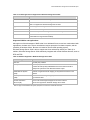
SPECIFICATIONS
AberNAS 110/116
1U, 19" Rackmount
1.0 Terabyte / 1.6 Terabyte
CIFS, NFS, NCP, HTTP and FTP
1.0 Terabyte / 1.6 Terabyte
1/2 Terabyte / 800 Gigabyte
2/3 Terabyte / 1.0 Terabyte
1.0 Terabyte / 1.6 Terabyte
Windows® Storage Server 2003
Intel Pentium 4 2.8GHz at 800MHz
Front Side Bus 512K Cache
512MB ECC Reg. DDR SDRAM
Integrated Marvell 4 port RAID
controller
4 Bays
4 x 250GB / 400GB SATA 8MB Cache
- 8GB OS Partition per Drive
- 242GB / 392GB Partition per Drive
Dual Intel Gigabit controller
2 x 10/100/1000 ports
Load Balancing, Teaming and Failover
350w
Included
5-Year Limited
- 17 -
ABERNAS 110/116 DISK PLACEMENT CHART
WARNING – The disk drive trays must be properly seated completely back into their
sockets and they must be in their proper positions in order to avoid software
corruption and/or hardware damage.
Please carefully read the following:
Your AberNAS by Aberdeen storage appliance has one row of four hard disk drives.
The columns are labeled alphabetically from left to right. For safety during shipment
to you, the drives have been removed and shipped separately.
The positioning stickers on the hard drive packages correspond to their placement
in the chassis. Proper placement of the drives is critical in retaining the integrity of
any software or operating system that has been loaded.
Column A
Row 1
A1
Column B
B1
Column C
C1
Column D
D1
Latch
Retaining Handle
Slide the hard drive into place with the retaining handle extended. When the drive
is fully inserted, push the retaining handle back until it is fully seated and snapped
into the latch.
Should you require technical assistance with this or any other aspect of your
Aberdeen server, contact us toll free at (800)552-6868 option 2 from 8:00am to
5:00pm PST.
- 18 -
APPENDIX - C
ABERNAS 221
- 19 -
ABERDEEN ABERNAS 221 SPEC SHEET
MAXIMIZE:
•
•
•
•
•
•
•
Network Storage Capacity
Hardware Redundancy and Reliability
Network Performance
Management Simplicity
Scalability
Cost / GB Ratio
Peace of Mind with a 5-Year Warranty
Inevitably you will need to replace or increase the capacity of your
network storage, application server storage or back-up storage. The
AberNAS by Aberdeen allows you to enjoy the benefits of a featurerich, high-performance network attached storage without the high
cost of ownership. The AberNAS by Aberdeen is the solution of
choice to provide the power and features to support today’s most
dynamic and demanding network infrastructures. Packed with
server management, security and mission-critical features the
AberNAS by Aberdeen can offer up to 2 terabytes in a 2U space with
the most competitive value in the marketplace.
Featuring 3DM Disk
Management Software.
As the ultimate reliable NAS server, the AberNAS 221 stresses
speed, ease of management and dependable storage.. Configured
with separate mirrored OS drives to provide system failover, the
AberNAS 221 provides a RAID 5 hot spare storage environment.
Yielding the best storage capacity the a 2U AberNAS 221 storage
appliance offers flexibility and speed without sacrificing on security.
- 20 -
For the system/storage administrator,
managing an organization’s growing
wealth of information has become an
increasingly complex, high pressure
undertaking.
MODEL
FORM FACTOR
BASE CAPACITY
PROTOCOL SUPPORT
MAX RAID 0
CAPACITY
MAX RAID 1
CAPACITY
MAX RAID 5
CAPACITY
MAX SINGLE
Microsoft® Storage Server 2003.
ARRAY SIZE
OPERATING SYSTEM
The system administrator must take into PROCESSOR
account rapidly changing storage
technologies. While there are many
MEMORY
storage solutions available today, not all RAID ENVIRONMENT
solutions scale well with organizational
HOT SWAP
growth, nor are all equally capable of
INCLUDED MIRRORED
delivering cost-effective high
OS/DATA DRIVES
performance solutions.
The new and enhanced data and storage
management capabilities of Microsoft®
Windows Server 2003 and Microsoft
Windows Storage Server 2003 are critical
tools in helping system and storage
administrators do more with less.
SPECIFICATIONS
AberNAS 221
2U, 19" Rackmount
2.0 Terabytes
CIFS, NFS, NCP, HTTP and FTP
2.00 Terabytes*
INCLUDED DATA
DISK DRIVES
ETHERNET
ETHERNET LOAD
BALANCING
POWER SUPPLY
RAILS
WARRANTY
* Includes a 140 GB Base
1.00 Terabyte*
1.75 Terabytes*
2.0 Terabytes
Windows® Storage Server 2003
Dual Intel Xeon 2.4GHz at 533MHz
Front Side Bus 512K Cache
2GB ECC Reg. DDR SDRAM
3ware® Escalade 8506-12
12 Bays
2 x 80GB SATA 8MB Cache
- 10GB OS Partition
- 70GB DATA Partition
8 x 250GB SATA 8MB Cache
Dual Intel Gigabit controller
2 x 10/100/1000 ports
Load Balancing, Teaming and Failover
460w Dual Hot Swap REDUNDANT
Included
5-Year Limited
RAID 1 Partition
- 21 -
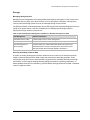
ABERNAS 221 DISK PLACEMENT CHART
WARNING – The disk drive trays must be properly seated completely back into their
sockets and they must be in their proper positions in order to avoid software
corruption and/or hardware damage.
Please carefully read the following:
Your AberNAS by Aberdeen storage appliance has four columns of three hard disk
drives. The columns are labeled alphabetically from left to right and the rows are
numbered from top to bottom. For safety during shipment to you, the drives have
been removed and shipped separately.
The positioning stickers on the hard drive packages correspond to their placement
in the chassis. Proper placement of the drives is critical in retaining the integrity of
any software or operating system that has been loaded.
Column A
Column B
Column C
Column D
Row 1
A1
B1
C1
D1
Row 2
A2
B2
C2
D2
Row 3
A3
B3
C3
D3
Latch
Retaining Handle
Slide the hard drive into place with the retaining handle extended. When the drive
is fully inserted, push the retaining handle back until it is fully seated and snapped
into the latch.
Should you require technical assistance with this or any other aspect of your
Aberdeen server, contact us toll free at (800)552-6868 option 2 from 8:00am to
5:00pm PST.
- 22 -
APPENDIX - D
ABERNAS 231/232
- 23 -
ABERDEEN ABERNAS 231/232 SPEC SHEET
MAXIMIZE:
•
•
•
•
•
•
•
Network Storage Capacity
Hardware Redundancy and Reliability
Network Performance
Management Simplicity
Scalability
Cost / GB Ratio
Peace of Mind with a 5-Year Warranty
Inevitably you will need to replace or increase the capacity of your
network storage, application server storage or back-up storage. The
AberNAS by Aberdeen allows you to enjoy the benefits of a featurerich, high-performance network attached storage without the high
cost of ownership. The AberNAS by Aberdeen is the solution of
choice to provide the power and features to support today’s most
dynamic and demanding network infrastructures. Packed with
server management, security and mission-critical features the
AberNAS by Aberdeen can offer up to 3 terabytes in a 2U space with
the most competitive value in the marketplace.
Featuring 3DM Disk
Management Software.
As the ultimate reliable NAS server, the AberNAS 231 stresses
speed, ease of management and dependable storage.. Configured
with separate mirrored OS drives to provide system failover, the
AberNAS 231 provides a RAID 5 hot spare storage environment.
Yielding the best storage capacity the a 2U AberNAS 231 storage
appliance offers flexibility and speed without sacrificing on security.
The AberNAS 232 is configured just as the 231 model yet is
provides even more TB capacity with the use of 400GB drives.
- 24 -
For the system/storage administrator,
managing an organization’s growing
wealth of information has become an
increasingly complex, high pressure
undertaking.
Microsoft® Storage Server 2003.
The system administrator must take into
account rapidly changing storage
technologies. While there are many
storage solutions available today, not all
solutions scale well with organizational
growth, nor are all equally capable of
delivering cost-effective high
performance solutions.
MODEL
FORM FACTOR
BASE CAPACITY
PROTOCOL SUPPORT
MAX RAID 0
CAPACITY
MAX RAID 1
CAPACITY
MAX RAID 5
CAPACITY
MAX SINGLE
ARRAY SIZE
OPERATING SYSTEM
PROCESSOR
MEMORY
RAID ENVIRONMENT
HOT SWAP
INCLUDED MIRRORED
OS/DATA DRIVES
SPECIFICATIONS
AberNAS 231/232
2U, 19" Rackmount
3.0 Terabytes / 4.8Terabytes
CIFS, NFS, NCP, HTTP and FTP
2.74 Terabytes / 4.39 Terabytes*
1.49 Terabytes / 2.39 Terabytes *
2.24 Terabytes / 3.59 Terabytes *
2.0 Terabytes / 3.2 Terabytes
Windows® Storage Server 2003
Dual Intel Xeon 2.4GHz at 533MHz
Front Side Bus 512K Cache
2GB ECC Reg. DDR SDRAM
3ware® Escalade 9506-12
12 Bays
2 x 250GB / 400GB SATA 8MB Cache
- 10GB OS Partition
- 240GB / 390GB DATA Partition
10 x 250GB / 400GB SATA 8MB Cache
INCLUDED DATA
DISK DRIVES
Dual Intel Gigabit controller
The new and enhanced data and storage ETHERNET
2 x 10/100/1000 ports
management capabilities of Microsoft®
ETHERNET
LOAD
Load Balancing, Teaming and Failover
Windows Server 2003 and Microsoft
Windows Storage Server 2003 are critical BALANCING
POWER SUPPLY
460w Dual Hot Swap REDUNDANT
tools in helping system and storage
administrators do more with less.
RAILS
Included
WARRANTY
5-Year Limited
* Includes a 240 GB Base RAID 1 Partition w/ 250GB drive
and 390 GB Base RAID 1 Partition w/ 400GB drive
- 25 -
ABERNAS 231/232 DISK PLACEMENT CHART
WARNING – The disk drive trays must be properly seated completely back into their
sockets and they must be in their proper positions in order to avoid software
corruption and/or hardware damage.
Please carefully read the following:
Your AberNAS by Aberdeen storage appliance has four columns of three hard disk
drives. The columns are labeled alphabetically from left to right and the rows are
numbered from top to bottom. For safety during shipment to you, the drives have
been removed and shipped separately.
The positioning stickers on the hard drive packages correspond to their placement
in the chassis. Proper placement of the drives is critical in retaining the integrity of
any software or operating system that has been loaded.
Column A
Column B
Column C
Column D
Row 1
A1
B1
C1
D1
Row 2
A2
B2
C2
D2
Row 3
A3
B3
C3
D3
Latch
Retaining Handle
Slide the hard drive into place with the retaining handle extended. When the drive
is fully inserted, push the retaining handle back until it is fully seated and snapped
into the latch.
Should you require technical assistance with this or any other aspect of your
Aberdeen server, contact us toll free at (800)552-6868 option 2 from 8:00am to
5:00pm PST.
- 26 -
APPENDIX - E
MICROSOFT WINDOWS STORAGE SERVER 2003
- 27 -
ABERNAS BY ABERDEEN EASY SETUP
If you connect a monitor (1024x768x85Hz resolution), a keyboard and a
mouse to your Aberdeen NAS Server for easy setup purposes:
Power up the device and Login as:
User:
Administrator
Password: monster
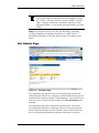
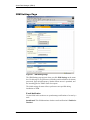
The easy Graphical User Interface (GUI) NAS interface will start. Click on
“Administer this Server Appliance” and a detailed help menu embedded into
interface will appear. If you see a connection error on Internet Explorer, simply
click “Try Again.”
If you don’t want to connect your Aberdeen NAS Server to a monitor, keyboard and
a mouse:
Connect the server to your network, turn it on and allow it approximately two (2)
minutes to boot up. Go to any computer connected to the same network, open up
your web browser and type https://abernas:8098
Enter the default login information:
User:
Administrator
Password: monster
The easy Graphical User Interface (GUI) NAS interface will start. Click on
“Administer this Server Appliance” and a detailed help menu embedded into
interface will appear. If you see a connection error on Internet Explorer, simply
click “Try Again.”
If your network has a special IP Number or a Layer 2-3 switch and there is no DHCP
Server present on your network, second method may not function and it will be
necessary to install a monitor, keyboard and mouse on the NAS Server.
Changing the RAID Array Setup (Only for Experienced Administrators)
Entering https://abernas:888 on any browser will give you access to the RAID
Array setup. If you change your Server name, replace “monster” with your server
name.
Menu Access
To Manage Disk Volumes or Remote Desktop menus, you must be using Internet
Explorer 5.5 or higher. For other menus, any web browser application should
function properly.
- 28 -
Introduction to Windows Storage Server 2003 Architecture
and Deployment
Microsoft Corporation
Published: July 2003
Abstract
Microsoft Windows® Storage Server 2003 is the latest version of Windows Powered NAS. Built on
the Microsoft® Windows Server™ 2003 operating system, Windows Storage Server 2003 is a
dedicated file server that offers dependable storage while integrating seamlessly with the existing
corporate network infrastructure. Easy to install and manage, Windows Storage Server 2003 offers
outstanding economics. It enables substantial file server consolidation and provides one of the best
platforms for simplified file sharing, backup and replication of businesses essential data.
This white paper introduces the reader to the new and enhanced features of
Windows Storage Server 2003 file server and network attached storage (NAS) technologies.
The information contained in this document represents the current view of
Microsoft Corporation on the issues discussed as of the date of
publication. Because Microsoft must respond to changing market
conditions, it should not be interpreted to be a commitment on the part of
Microsoft, and Microsoft cannot guarantee the accuracy of any information
presented after the date of publication.
This White Paper is for informational purposes only. MICROSOFT
MAKES NO WARRANTIES, EXPRESS OR IMPLIED, AS TO THE
INFORMATION IN THIS DOCUMENT.
Complying with all applicable copyright laws is the responsibility of the
user. Without limiting the rights under copyright, no part of this document
may be reproduced, stored in or introduced into a retrieval system, or
transmitted in any form or by any means (electronic, mechanical,
photocopying, recording, or otherwise), or for any purpose, without the
express written permission of Microsoft Corporation.
Microsoft may have patents, patent applications, trademarks, copyrights,
or other intellectual property rights covering subject matter in this
document. Except as expressly provided in any written license agreement
from Microsoft, the furnishing of this document does not give you any
license to these patents, trademarks, copyrights, or other intellectual
property.
The example companies, organizations, products, people and events
depicted herein are fictitious. No association with any real company,
organization, product, person or event is intended or should be inferred.
© 2003 Microsoft Corporation. All rights reserved.
Microsoft, Active Directory, Windows, and Windows NT are either
registered trademarks or trademarks of Microsoft Corporation in the
United States and/or other countries.
The names of actual companies and products mentioned herein may be
the trademarks of their respective owners.
Microsoft® Windows Storage Server 2003 White Paper
Contents
Introduction.................................................................................................................................... 1
Overview of Windows Storage Server 2003................................................................................ 2
What is Windows Storage Server 2003? ..................................................................................... 2
Advantages of Windows Storage Server 2003 ............................................................................ 2
The Basics: How NAS Works ....................................................................................................... 4
File Serving Component .............................................................................................................. 4
Hardware Component .................................................................................................................. 4
Storing Component ...................................................................................................................... 4
Optimizing NAS............................................................................................................................ 5
Windows Storage Server 2003 Features ..................................................................................... 6
Networking ................................................................................................................................... 6
File Serving .................................................................................................................................. 7
Storage......................................................................................................................................... 9
NAS Management Software ...................................................................................................... 10
Performance............................................................................................................................... 11
Integrated Snapshots ................................................................................................................. 12
Improved End-User Experience................................................................................................. 12
New Features in Windows Storage Server 2003 ...................................................................... 14
Volume Shadow Copy Service (VSS)........................................................................................ 14
Virtual Disk Service (VDS) ......................................................................................................... 15
Multipath I/O (MPIO) .................................................................................................................. 16
Distributed File System (DFS) ................................................................................................... 17
NAS Deployment Scenarios ....................................................................................................... 18
File Serving ................................................................................................................................ 18
Server Consolidation.................................................................................................................. 20
Local and Remote Site Replication for Business Continuity...................................................... 20
NAS-SAN Fusion ....................................................................................................................... 22
Summary ...................................................................................................................................... 23
Related Links ............................................................................................................................... 24
Microsoft® Windows Storage Server 2003 White Paper
Introduction
Development of technologies delivering storage over the network has revolutionized the availability,
distribution and accessibility of storage resources. Attaching storage directly to the company network
helps to eliminate or reduce the drawbacks business experience when using directly attached
storage. These drawbacks include:
•
Limited storage capacity and scaling constraints as data assets grow.
•
Proliferation of computer hardware and software to meet increased storage capacity needs.
•
Proliferation of hardware and software necessary to protect the data allocated to new storage.
•
Increased management complexity for the system administrator(s) configuring and maintaining IT
client and server systems.
•
Poor or inconsistent protection of data on client desktops and laptops.
•
Limited or laborious access to data, especially between company workgroups, departments and
branches.
•
Temporary or permanent loss of data resulting from hardware failures, data corruption or user
error.
•
Spiraling costs associated with capital expenditure, increased staffing, and production downtime
resulting from data loss.
Network attached storage (NAS) is one solution to these challenges. NAS storage and file serving
devices can be attached directly to the company intranet. Storage directly attached to the network
becomes accessible to all computers that can access the network. NAS servers are designed for
ease of deployment: they can be plugged directly into the network without disruption of services,
management is minimal and simplified, and they are largely maintenance free. NAS devices are an
ideal means by which to consolidate file servers and backup equipment and to expand storage
capacity.
A second networked-storage solution is the installation of a storage area network (SAN). Unlike NAS
solutions, these dedicated storage networks require considerably more planning to deploy, and their
management is more complex. SAN solutions are ideal for database and on-line processing
applications requiring rapid data access, but because SAN storage devices serve block-level data
rather than files, the installation of a Fibre Channel network to transport the SCSI (Small Computer
1
System Interface) commands is necessary .
A third storage network solution is a hybrid one: NAS devices can be attached to SANs. In this
configuration, the NAS components necessary for filing are physically separated from the
components necessary for storing: a NAS “head” or “gateway” (containing the filing functionality)
attaches to the LAN network, and behind that lies the storage component—a “backend” SAN
consisting of the Fibre Channel network (wiring and switches) and the storage disks.
1
Microsoft, with its iSCSI initiator software released in June 2003, is enabling block transport over company intranets.
See the Enterprise Storage Division white paper, “Microsoft Support for iSCSI” for details.
Microsoft® Windows Storage Server 2003 White Paper
Overview of Windows Storage Server 2003
What is Windows Storage Server 2003?
Microsoft® Windows® Storage Server 2003 is a network attached storage (NAS) operating system
that enables original equipment manufacturers to build appliances that provide dedicated file serving
capabilities and storage on the network. Windows Storage Server 2003 is built on top of Microsoft
Windows Server™ 2003, which ensures that NAS devices built upon the Windows Storage Server
operating system have all the performance and scalability benefits associated with
Windows Server 2003.
A NAS appliance built Windows Storage Server 2003 is designed to perform without requiring a
monitor, keyboard and mouse. Instead, this “headless” appliance is remotely managed through a
Web-based user interface for the minimal configuration tasks required for setup. Unlike application
servers which require proper planning to implement well, NAS devices built with
Windows Storage Server 2003 are designed to be deployed in under 15 minutes, and can be
attached directly to the company local area network (LAN) with no interruption to services. Once
plugged in, these NAS devices require minimal maintenance.
2
Unlike proprietary solutions, Windows Storage Server 2003 works with standard hardware from
multiple original equipment manufacturers (OEMs). This gives businesses maximum flexibility in
choosing among vendors with the hardware solution that best meets their needs.
Advantages of Windows Storage Server 2003
Windows Storage Server 2003 is designed for simplicity, reliability and performance. NAS appliances
built on Windows Storage Server operating system integrate seamlessly into the IT network to
provide one of the most economical file serving and network attached storage solutions available to
departmental and enterprise-sized businesses.
•
Ease of Deployment. Depending on the expertise of the system administrator and the
complexity of the computing environment, installation of an application or general purpose server
can take anywhere from several hours to a day or more of work. Because
Windows Storage Server 2003 comes preconfigured, other than using the web browser interface
to set up users and shares, the only installation work necessary is plugging the device into the
company LAN. In less than 15 minutes, gigabytes to terabytes of storage can be made available
to users across multiple OS platforms.
•
Simple Management. Windows Storage Server 2003 can be managed remotely though Terminal
Services sessions or through a Web browser interface from any desktop on the network. Because
Windows Storage Server 2003 uses the Windows operating system, administrators already
familiar with Windows do not have to learn a new NAS operating system.
•
Dependability. Windows Storage Server 2003 is designed to fully support redundant hardware
components—disks, power supplies and fans—to provide continuous and uninterrupted
availability should a hardware failure occur. And because NAS devices are designed this way, the
potential points of hardware failure are fewer than with general purpose servers.
2
Any system designed to run an operating system.
Microsoft® Windows Storage Server 2003 White Paper
•
Enhanced Data Protection. Through built-in point-in-time shadow technology,
Windows Storage Server 2003 helps businesses keep their data online 24x7 year-round. Using
the infrastructure provided by Windows Server 2003 Volume Shadow Copy Service (VSS), the
system administrator can use point-in-time shadow copy technologies to make up to 512
snapshots per volume using NTBACKUP (of which 64 are reserved for Shadow Copies for
Shared Folders). These shadow copy backups are available for rapid restores should the need
arise. Unlike tape backups which can take hours to restore, these shadow copy backups can be
restored in minutes.
The end user can also benefit from point in time imaging technologies, using the Shadow Copies for
Shared Folders (SCSF) feature. SCSF enables users to restore accidentally deleted or overwritten
files or entire folders without the need for IT intervention. A maximum of 64 SCSF per volume can be
created.
•
ISV Utility Support. NAS devices developed with Windows Storage Server 2003 include all of
the benefits of application support available in Windows Server 2003. Critical ISV utilities, such as
antivirus, backup, replication and disk quota software, are immediately available and supported in
Windows Storage Server 2003. NAS devices not based on Windows Storage Server 2003 are not
able to support these kinds of products without special versions, or those operational procedures
must be performed from application servers on the NAS files and file.
•
Robust Security. Because it can be integrated seamlessly with Active Directory services,
Windows Storage Server 2003 can take advantage of the Windows security features such as
data and file encryption, network authentication, secure network transport, and network wide
group policies.
•
Load Balancing and Server Fail Over. Windows Storage Server 2003 integrates effectively with
the Distributed File System, enabling effective management of the servers and files on the
business network. DFS works to provide a single hierarchical view all the servers and their
shares. Replicating the data across multiple servers and keeping the data synchronized with File
Replication Service (FRS) is an effective way to balance the network load. In the event that a
server fails, DFS will automatically redirect clients to the closest available server.
Microsoft® Windows Storage Server 2003 White Paper
The Basics: How NAS Works
This section provides a brief introduction to how the NAS server works, and is included to help
provide the context for many of the NAS features available with Windows Storage Server 2003. Like
all NAS servers, Windows Storage Server 2003 functionally and architecturally consists of three
3
components: the filing system, the wiring (and related hardware), and the storage (disk ). These
components together provide the functionality necessary to fulfill client system application requests
for data stored on the NAS device.
Application requests to read or write data are initiated by the client system, and can be directed to the
storage local to the client (embedded or directly attached storage), or can be redirected over the
network to the NAS device using network transport protocols. These I/O requests are then processed
by the NAS operating system before being passed to the disk devices for storage.
File Serving Component
The process of storing and retrieving the data requested by user applications is known as file serving.
File serving is under control of the operating system software.
1. Application I/O requests (to read or write data) flow from client-side applications over the LAN to
the NAS operating system (kernel), which queues and schedules the various client application
requests. These requests then pass to the file system and the volume manager of the operating
system.
2. The file system portion of the operating system controls security and determines whether or not a
file can be created, opened, written to. The file system also ensures that the file is addressed to
the correct storage destination. The I/O request then passes from the file system through the
Volume Shadow Copy Service layer (where it may or may not be processed) to the volume
manager.
3. The volume manager portion of the operating system readies the data for the specific device(s) it
4
will be passed onto for storage . The Virtual Disk Service (see later section in this paper) is a
component of the volume manager (but not a component of I/O requests).
Hardware Component
Having passed out of the operating system, the I/O request travels over the host bus to the host I/O
controller, which is responsible for correctly addressing the appropriate storage device and correctly
transferring the I/O request commands and data across the storage I/O bus to the storage device.
Storing Component
Having passed into the storage device, the application request (data) is stored on the appropriate
physical or logical disk, as directed by the file system.
3
Disks can be both physical and logical (virtual).
It is at this step that the data associated with the application request is converted from file format into the constituent
granular blocks that are written to storage devices.
4
Microsoft® Windows Storage Server 2003 White Paper
Optimizing NAS
5
Vendors can configure NAS hardware (and firmware ) such that it is optimized for network file I/O
processing and storage. These components include the NAS processor, memory and caching, and
the storage devices. There are many different ways to optimize file serving, and the particular
approaches taken are vendor specific.
The next section describes the networking, file serving and storage features in
Windows Storage Server 2003 that drive these capabilities.
5
Software on the vendor hardware; not part of the OS.
Microsoft® Windows Storage Server 2003 White Paper
Windows Storage Server 2003 Features
This section highlights the networking, file serving and storing capabilities of
Windows Storage Server 2003. This section provides feature highlights. For a summary of the major
advances in Windows Storage Server 2003, see “Key Improvements Since
Windows Powered NAS 2.0.”
Networking
Network Data Transmission Protocols
In order for clients to access storage on the NAS device, they must be connected to the local
area network, and network transport must be enabled. Clients most commonly connect to the
NAS server over Ethernet cabling using the TCP/IP protocol. Depending on the system platform,
other protocol layers may also be necessary for network transport. Windows Storage Server 2003
provides support for network protocols used by not only Windows systems, but also by Unix and
Apple systems (see Table 1), enabling networking across multiple platforms.
Table 1. Networking Protocols Supported by Windows Storage Server 2003
Network Protocols
Additional Information
TCP/IP
Used to connect hosts to the Internet.
AppleTalk
Networking protocol for Apple computers.
IPX
Internet packet exchange. (Administration through Remote Desktop.)
NetBEUI
NetBIOS Extended User Interface, used for Windows environments.
SNMP
Simple Network Management Protocol, internet standard for network
management.
Telnet
Provides remote terminal access to host.
Fibre Channel
Transmits block-level data; most common in SAN configurations.
Ethernet
Physical network, transmits files; most common transport for NAS.
Network Security
Windows Storage Server 2003 uses the authentication services of Server 2003 to ensure that only
those users with permission to access data can do so. An additional layer of protection is available
through the data encryption capabilities of the Windows operating system (see Table 2). The NAS
Windows Storage Server is able to support security features for Unix and Macintosh environments, as
well as earlier Windows platforms.
Microsoft® Windows Storage Server 2003 White Paper
Table 2. Security and Authentication Support in Windows Storage Server 2003.
Security and
Authentication
Additional Information
Kerberos
Network authentication protocol for client server configurations.
SSL
Secure Socket Layer protocol, provides connection security for Web
servers.
IPsec
Internet Protocol Security, provides encryption for network transmission.
Active Directory
Directory service for Windows OS, acts as central authority for network
security.
Windows NT Domain
Administration (including security and authentication) of users, groups,
servers etc in NT environments.
NTLM
Windows NT LAN Manager provides security for connections between
NT clients and servers.
NIS
Network Information System (for Unix servers).
Apple UAM
User Authentication Module.
File Serving
File Sharing Protocols
File serving, as discussed earlier, is the process of opening, closing, reading and writing files. In order
for file serving to be enabled over the network, file sharing protocols must be supported. These
protocols enable clients to make requests and receive responses from remote devices, such as a
NAS storage box.
Many NAS devices enable only simple file processing because they include support only for the
standard file systems: the Common Internet File System (CIFS) and Network File System (NFS). In
contrast, Windows Storage Server 2003, with its support for multiple file sharing protocols (Table 3),
allows for complex multi-platform file processing. In addition to Windows clients,
Windows Storage Server 2003 supports file processing for Unix, Macintosh, and Web HTTP clients,
among others.
Microsoft® Windows Storage Server 2003 White Paper
Table 3. File Sharing Protocols Supported in Windows Storage Server 2003
Protocols
Additional Information
SMB/CIFS
Enables Windows-based file sharing.
NFS
Enables Unix/Linux-based file sharing.
NFS 3.0 supported in Windows Storage Server 2003.
AppleTalk
Enables Apple file sharing.
HTTP
Enables web file sharing.
WebDAV
Enables desktop users to manage web based files using HTTP.
NetWare
Enables Novell-based file sharing.
Administration through Remote Desktop.
Supported Utilities and Applications
Although one of the advantages of NAS is that it is a dedicated file server and not overburdened with
applications, the data on the server nevertheless requires protection from data corruption, and the
possibility of hardware failure. Because it is based on Server 2003 operating system,
Windows Storage Server 2003 is able to support anti-virus and backup utilities (see Table 4). In
addition, Windows Storage Server 2003 seamlessly integrates with critical Windows features, such as
DFS and FRS.
Table 4. Software Supported in Windows Storage Server 2003
Software Support
Additional Information
Anti-virus
Via third party software.
Backup
Via third party software.
Includes the backup utility NTBACKUP which uses VSS and SCSF to
backup both system and user data with shadow copies.
1
Distributed File System
(DFS)
Enables a single hierarchical mapping of all systems and shares on the
network
File Replication Service
(FRS)
Enables remote mirroring through replication
Internet Information
Services (IIS)
Tool to host and manage web pages on intranet or internet.
Synchronizes data
1
Version 6.0 supported in Windows Storage Server 2003.
Web UI support for Distributed File System (DFS) does not include or enable FRS scenarios.
Microsoft® Windows Storage Server 2003 White Paper
Storage
Managing Storage Devices
Management and configuration of the storage disks (both physical and logical) is under control of the
Virtual Disk Service (VDS). (See “New Features” for more information.) Allocation of disk space to
users is performed through quotas, and can be managed through a user interface.
The Enterprise Edition of Windows Storage Server 2003 supports the Automated Deployment Service
(ADS) as an optional add-on. ADS is a scriptable service enabling rapid and highly effective
deployment of large numbers of new servers.
Table 5. Disk and Deployment Management Capabilities in Windows Storage Server 2003
Disk Management
Additional Information
Virtual Disk Service (VDS)
Includes sample code for volume management
Quota Management
Enables administrators to limit the storage accessible by each user.
Automated Deployment
Services (ADS)
Enterprise Edition only. ADS enables administrators to perform script
based administration of large scale deployments of Windows servers.
ADS replaces Multi-Device Manager (MDM) in WP NAS 2.0.
Ensuring Availability of Stored Data
A number of existing technologies have been enhanced and a number of new features have been
added to Windows Storage Server 2003 to help keep a business’s data highly available. These
technologies range from tools to ensure hardware components are operating effectively and at high
performance, to technologies enabling hardware (MPIO) and software (clustering) redundancy, to
data availability techniques for redundancy (VSS and RAID) and high performance (RAID—redundant
array of inexpensive disks).
Microsoft® Windows Storage Server 2003 White Paper
Table 6. Features Enhancing System Reliability and Data Availability
Reliability/
Additional Information
Availability
Volume Shadow Copy
Service (VSS)
Enables up to 512 point-in-time copies per volume, of which 64 are
reserved for Shadow Copies for Shared Folders if enabled on the
volume.
This service replaces the Persistent Storage Manager (PSM) in WP NAS
2.0.
Clustering
Provides application failover.
Windows Storage Server 2003 Enterprise Edition supports up to 8 nodes
(WP NAS 2.0 supports a maximum of 2 nodes).
Software RAID 0, 1, 5
RAID types provide differing levels of data protection and redundancy.
VDS also enables hardware based RAID.
Multipath I/O (MPIO)
Enables high performance and high availability through multiple paths to
storage.
System Monitoring
Monitors performance of the operating system. Allows system
administrator to assess I/O performance with different devices.
Watchdog Timer
Detects system hangs; can be programmed to reboot system after a
given time.
NAS Management Software
Depending on the complexity of the deployment scenario, the need for NAS management ranges
from the minimal (plug and play) to the considerably more complex (see Table 5).
Windows Storage Server 2003 provides a number of different interfaces to meet such management
needs, including both local and web-based UIs (see Table 7).
Table 7. Management Interfaces in Windows Storage Server 2003
Management
Additional Information
Web User Interface (UI)
Enables administrators to remotely manage users, create shares, and
control backups and similar tasks from any location on the network or
internet.
Remote Desktop
Enables remote control of other systems for administration.
Microsoft® Windows Storage Server 2003 White Paper
Key Improvements Since Windows Powered NAS 2.0
Windows Storage Server 2003 has been improved in a number of key areas relative to
Windows Powered NAS 2.0. This section highlights improvements in the key areas of file serving
performance, integrated snapshots, and the user interface.
Performance
As a dedicated file server, the speed with which NAS boxes can handle I/O read and write requests is
a critical factor in overall performance of systems on the network. Windows-based NAS boxes
6
communicate with client systems using the SMB (server messenger block) or CIFS (common
internet file system) protocol for Windows-based systems. For Unix-based systems, the NFS (network
file system) protocol is used.
SMB Performance
The industry standard in measuring SMB/CIFS file server performance for Windows Clients is
NetBenchTM benchmarking software. File server performance is measured as throughput (megabits
per second) versus number of clients.
Comparisons of Windows Storage Server 2003 and NAS 2.0 using the same hardware configurations
directly capture improvements in the Windows operating system performance. These improvements
stem from changes to the kernel (improved caching, buffering, and the like), as well as changes
reflected in the use of SMB in 2003 versus CIFS in 2000. Differences between studies capture
differences attributable to different hardware configurations.
rd
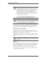
In both internal MS benchmarks using NetBench and a commissioned 3 party benchmark test, the
rd
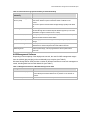
performance of Windows Storage Server 2003 is greatly enhanced in comparison to NAS 2.0. In 3
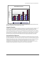
7
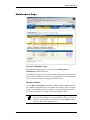
party Veritest comparison of file serving in Windows Storage Server 2003 and NAS 2.0, peak
throughput on Windows Storage Server 2003 is 35-85% faster than Windows Powered NAS 2.0,
8
depending on whether there are one, two, four or eight processors (see Figure 1). Internal Microsoft
tests, using a different hardware configuration, put the overall throughput at 100% or above for each
of the four processor configurations.
NFS Performance
The industry standard for measuring NFS file server performance for Unix clients is based on the
Spec SFS benchmark program produced by the Standard Performance Evaluation Corporation. Spec
SFS scores file server performance in terms of I/O throughput per second (IOPS). In internal MS
9
tests using Spec SFS, file serving performance increased from 5040 IOPS in NAS 2.0 to 7500 IOPS
in Windows Storage Server 2003, a 50% increase.
6
SMB is Server 2003’s enhanced version of CIFS (native to Server 2000).
See the report at www.veritest.com/clients/reports/microsoft.
8
It is important to note that these performance improvements are seen only when upgrade client software is loaded onto
the client systems.
9
For configuration details, see Windows Storage Server 2003 OEM training Guide.
7
Microsoft® Windows Storage Server 2003 White Paper
Peak SMB Performance
1200
Throughput(Mbps)
1000
800
600
400
200
0
1P
2P
Windows 2000 Server
4P
8P
Windows Server 2003
Figure 1. NetBench comparison of file serving performance in NAS 2.0 (Windows 2000 Server) and
Windows Storage Server 2003 (Windows Server 2003).
Integrated Snapshots
rd
In NAS 2.0, point-in-time imaging (snapshot) technology is only available through the integration of 3
party advanced backup software. In Windows Server 2003, snapshot technology is part of the
Volume Shadow Copy Service (VSS) and is fully integrated into the operating system, thus making it
part of the Windows Storage Server 2003 package. Snapshot technology enables open file backups
and fast restores. The technology is especially useful when the goal is the restoration of individual
files, which can be done by the end user without the need for system administrator intervention.
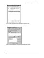
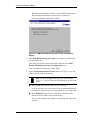
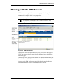
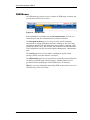
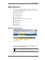
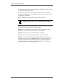
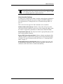
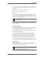
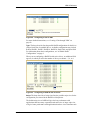
Improved End-User Experience
Windows Storage Server 2003 has a number of enhanced user interfaces (UIs) for the end user and
the system administrator. On the client side, the Previous Versions user interface (Shadow Copies for
Shared Folders) allows end users to directly restore their own files in the event of accidental deletion,
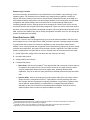
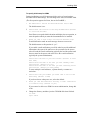
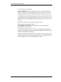
overwriting or file corruption (Figure 2). On the system administrator side, UIs for volume
defragmentation, task scheduling, folder and share management, volume management, and UPS
management make administration of storage much more convenient than before.
Microsoft® Windows Storage Server 2003 White Paper
Figure 2. Client user interface used to restore previous versions of a file.
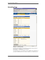
Figure 3. System administrator user interface for scheduling shadow copies.
Microsoft® Windows Storage Server 2003 White Paper
New Features in Windows Storage Server 2003
The following are new features in Windows Storage Server 2003.
•
Volume Shadow Copy Service
•
Virtual Disk Service
•
MPIO
•
DFS
Volume Shadow Copy Service (VSS)
The Volume Shadow Copy Service (VSS) is an infrastructure that makes possible enhanced data
protection though high fidelity backups, rapid data restores, and data transport.
VSS is a component of the operating system, and as such, is not directly accessed by users. Instead
the Volume Shadow Copy Service coordinates with user applications, backup applications and
storage hardware to enable the creation of point-in-time shadow copies of data on single or multiple
volumes without significantly impacting performance.
High Fidelity Backups
Shadow copy creation is a highly effective means of protecting data with several advantages over
traditional tape backups when the goal is not long-term archiving. Tape-based technologies are timeintensive to run, impose a considerable bandwidth burden on the local network, and can have data
inconsistency issues if applications are open during the backup process. As a consequence, tape
backups tend to be scheduled relatively infrequently and at times when applications are not in use
(such as nights or weekends)—a strategy that can work reasonably well for companies that do not
require 24x7 operations. In contrast, shadow copies can be created in seconds, without the impact on
network traffic that tape backups impose. Additionally, because the shadow copy process allows
open files to be backed up without data inconsistency issues, they can be scheduled at any time, and
much more frequently than tape backups.
Fast Restores
In the event of data loss, shadow copy restoration offers significant advantage over tape restores.
Because the shadow copies can be saved on storage arrays on site, they can be accessed directly,
without the need to travel offsite to a tape data vault, locate and bring back a tape. Even more
significantly, shadow copy restores takes only minutes to complete, while tape restores, depending
on the type of backup (full, differential or incremental) and the amount of data, can take hours or even
days to do correctly.
Shadow Copies for Share Folders
System administrators are not the only people to benefit from the fast restore functionality enabled by
VSS. System administrators can activate Shadow Copy for Shared Folders, thereby enabling end
users who overwrite or accidentally delete a file to restore a previous version of a file for themselves,
rather than having to recreate the file or request that a system administrator do a high cost single file
restore from tape.
Microsoft® Windows Storage Server 2003 White Paper
Shadow Copy Transport
All of the functionality discussed above is provided with the in-box shadow copy technology on the
operating system. The exception to this is shadow copy transport among systems—whether for
backup, data mining, testing or fast restores—which requires a hardware provider on the SAN. In a
direct attached storage configuration, this data transport between servers is physical. In a NAS-SAN
configuration with pooled storage, data on the SAN can be accessed (through masking and
unmasking) between servers. Although access to the storage pool is shared, each server can only
access the specific LUNs (Logical Unit Number) assigned to it (since two servers cannot both write to
the same volume without potentially causing data corruption). But using the hardware provider on the
SAN, a point-in-time shadow copy can be virtually “transported” to another server for use, through the
process of masking and unmasking.
Virtual Disk Service (VDS)
In order for a server to use new storage disks, they must first be made accessible to the server and
then formatted for use. Virtual Disk Service (VDS) controls the process of making storage accessible
to systems that need it. While it is irrelevant to application (or the user) how the data is stored—
whether it is on a single physical disk or spanned across several disks (a logical unit), in terms of data
protection and performance, the impact of how the data is stored is significant. Thus VDS can either
present a physical disk or a logical disk to a server. Physical disks do not require the first two steps.
1. Create logical units, assign number ids (these are now referred to as LUNs)
2. Unmask LUNs to server
3. Create partitions and volumes
4. Format the file system
10
•
Basic Disks. VDS is used to partition each physical disk and to create the volumes that can
be mapped to drive letters for use. These volumes are known as “simple volumes” and do
not span multiple disks. Basic disks are the legacy disks, predating Windows 2000
capabilities. They do not offer the same performance and data protection that dynamic disks
offer.
•
Dynamic Disks. VDS can be employed to create dynamic disks which can consist of either
11
simple volumes or multi-partition volumes . Multi-partition volumes physically span more
than a single disk but nevertheless are logically considered a single volume. Dynamic disks
can be spanned, striped (RAID-0), mirrored (RAID-1) or stripped with parity (RAID-5),
depending on the level of performance and data protection desired. VDS can be used to
expand dynamic disks to make more space available to a volume.
10
Physical disks are divided into sectors; contiguous sectors are partitions. In the case of basic disks, the volumes are
created within partitions, and are thus restricted to a single disk.
11
Volumes can span one or more partitions on the same or multiple disks. Dynamic disk types include RAID
configurations, and can offer better performance and reliability than basic disks.
Microsoft® Windows Storage Server 2003 White Paper
Although many vendors provide NAS appliances preconfigured with RAID, system administrators
might want to use VDS to customize the storage solution to meet specific data storage needs,
whether relating to capacity, performance or data protection.
VDS can also be used to attach a NAS device to a back-end SAN. These NAS “heads” contain only
the file serving capabilities; for highly scaleable and highly available pooled storage, they plug into a
Fibre Channel SAN. Each storage unit on the SAN must have its storage configured and made
accessible to the appropriate servers only. Since it is common for storage on the SAN to be from
multiple hardware vendors, prior to Windows Server 2003 and Windows Storage Server 2003 it was
necessary for the system administrator to configure each device using a vendor-specific storage
management application. Not only did this mean using hardware-specific management utilities, it
frequently meant that the system administrator had to physically go to each storage device to do each
configuration.
Windows Storage Server 2003’s Virtual Disk Service helps alleviate these administration complexities
in a NAS backend SAN configuration by providing a single management interface for multivendor
storage devices. The system administrator can manage all storage devices directly from a single
management console, and query and configuration operations are common across all managed
devices.
In this scenario, VDS functionality is enabled through hardware vendor support. Each hardware
vendor must supply a VDS “provider” for the storage hardware. The hardware provider translates the
VDS standard APIs (application programming interface) into instructions specific to the storage
device. With communication enabled between the Virtual Disk service and the storage hardware, the
system administrator can now use a single storage management interface to communicate with
multivendor storage devices.
Multipath I/O (MPIO)
Multiple or redundant paths between storage devices and the systems that use them enable
persistent data availability and high I/O performance. In essence, these technologies provide for an
alternate connection in case of failure of the primary I/O path, and, optionally, multiple paths to
improve performance or balance loads.
MPIO software included in Windows Storage Server 2003 is not a feature of the operating system,
but is supported through the Driver Development Kit (DDK). Multipathing allows a host to have up to
32 paths to access an external storage device, which facilitates failover and load balancing.
Multipathing technology is critical in ensuring highly available data to businesses. In the past,
multipathing was a solution only available to large scale enterprises; now this high availability solution
is available to any organization using only Windows Storage Server 2003 (and Windows Server 2003)
technologies.
Microsoft's MPIO delivers a standard and interoperable path for communication between storage
products and Windows Server. With a platform upon which multiple third-party storage systems can
reliably interoperate, businesses have greater choice when building a high-quality, highly available
network storage system, and system administrators will have the flexibility to incorporate products
from multiple vendors into a single, interoperable and highly available storage infrastructure.
Microsoft® Windows Storage Server 2003 White Paper
Distributed File System (DFS)
The Distributed File System enables the system administrator to create single hierarchical mapping of
all systems and shares on the network. By uniting files on different computers into a single
namespace, users do not have to sort through a network of dozens of servers, each with their own
separate directory structure, but instead see the files as if they resided on a single computer.
With the latest version of the server operating system, DFS has been enhanced to allow multiple DFS
roots on a single server, thus reducing administrative and hardware costs of managing multiple
namespaces and multiple replicated namespaces. In addition, DFS now delivers more reliable loadbalancing, better file replication between DFS sites and servers, and closest-site selection for users
accessing the network. Closest-site selection ensures that in the event of server failure or scheduled
maintenance, users are automatically routed to another server on the network that has a replica of
the data. For best performance and lowest cost, clients are rerouted to the site closest to them.
Microsoft® Windows Storage Server 2003 White Paper
NAS Deployment Scenarios
The following are common NAS deployment scenarios.
•
File Serving
•
Server Consolidation
•
Local and Remote Site Replication for Business Continuity
•
NAS-SAN Fusion
File Serving
Businesses need reliable file servers that can provide highly available data at a reasonable cost. Offthe-shelf, general-purpose servers are not typically configured with fully redundant hardware
components. Using a general-purpose server for file serving and running applications can
compromise both tasks. In particular, file serving can be negatively impacted by the overhead
associated with running applications, as well as by the risks of system crashes should an application
fail. General-purpose servers have the additional disadvantage of being platform specific,
necessitating a different file server to serve clients on different platforms.
In contrast, NAS filers confer a number of advantages. NAS appliances are designed for high
reliability: they are built with redundant disks, NICs (for failover data paths), and power supplies.
This redundancy of hardware components makes NAS devices highly reliable file servers helping
to ensure highly available data.
Because NAS devices built on Windows Storage Server 2003 are dedicated file servers, they do
not carry application overhead, and they are not vulnerable to application-related problems.
Moreover, because Windows Storage Server 2003 supports multiple file sharing protocols, file
serving to clients on Windows, Unix or Macintosh computers, and sharing between them, can be
accomplished without the need for a specialized file server for each platform.
Microsoft® Windows Storage Server 2003 White Paper
Figure 4. File serving between network clients and Windows Storage Server 2003.
Microsoft® Windows Storage Server 2003 White Paper
Server Consolidation
As companies add more and more servers to meet demands for increased storage capacity,
equipment, licensing, maintenance (power, space, servicing) and management costs all escalate.
Adding a Windows Storage Server 2003 based device to the network allows businesses to
consolidate multiple file servers into a single more powerful NAS device. Given the broad file
serving capabilities of Windows Storage Server 2003, even file servers running on different
platforms (such as Unix or Novell) can be consolidated onto a NAS device, greatly simplifying
management across systems. Related equipment, such as backup devices, can also be
consolidated. System management is much simpler with fewer devices requiring space, servicing
(such as applying patches or maintaining versioning), and backup and restore services. For every
12
NAS device replacing multiple existing servers , the associated licensing costs are eliminated.
Figure 5. Consolidation of several multi-platform servers onto a single Windows Storage Server 2003
NAS device. This scenario enables the consolidation of tape drives into a single tape array.
Local and Remote Site Replication for Business Continuity
NAS servers using Windows Storage Server 2003 software technologies enable businesses to
build fault tolerant solutions designed to keep data highly available.
NAS devices on a LAN can use the replication technologies to replicate data between one NAS
device and another. In the event of network failure or the outage of a NAS device, a second NAS
device can assume the identity of a nonfunctioning filer and continue serving files to clients
without interruption of services. When the nonfunctioning NAS device returns, it takes back its
identity, resynchronizes its data with the active NAS device, and resumes file serving.
This process of replication and failover also works on a wide area network (WAN). Replication
and synchronization occurs over the WAN between NAS devices. Should one branch site
succumb to disaster or be shut down for a planned outage, clients accessing that NAS device are
redirected to a second NAS device at a different branch.
NAS devices are also useful to remote sites for a different reason. Branch offices often do not
have the IT staffing expertise to effectively deploy general-purpose servers. Because they are so
simple to deploy and maintain, NAS file servers are the perfect plug and play solution for these
remote sites.
12
The number of servers that can be consolidated on a NAS device depends how powerful the server capabilities are,
and how many clients are served. Microsoft tests have demonstrated that up to 25 Widows NT servers can be
consolidated into a single NAS device.
Microsoft® Windows Storage Server 2003 White Paper
Figure 6. Replication of data between NAS Windows Storage Server 2003 devices deployed at
different branch sites.
Microsoft® Windows Storage Server 2003 White Paper
NAS-SAN Fusion
NAS devices can be seamlessly integrated into a storage area network, providing clients access
to unlimited storage. In this configuration, NAS storage is separated from the NAS filing function
and placed on the SAN. The NAS head now acts as a gateway to the SAN, controlling distribution
of the data over the network and providing clients with maximum scalability and high-performance
storage solutions.
NAS-SAN fusion also enables system administrators to move NAS backups off the LAN onto the
storage network for highly efficient and extremely fast backups that do not impact LAN
performance.
Figure 7. Windows Storage Server 2003 (NAS “head”) integrated into storage area network.
Microsoft® Windows Storage Server 2003 White Paper
Summary
Windows Storage Server 2003 provides scalable, high performance storage solutions to businesses
of all sizes. Built on the Windows Server 2003 operating system, this successor to Windows Powered
NAS broadens usability and interoperability for both end users and system administrators. Using
Shadow Copies for Shared Folders, end users are empowered to recover their own lost data without
IT intervention, thereby improving their own efficiencies and helping the business save money.
System administrators benefit from the seamless integration of Windows Storage Server 2003 into
existing networks, multi-platform file-serving capabilities, and built-in point in time imaging capabilities
for highly efficient backup and restores.
Microsoft® Windows Storage Server 2003 White Paper
Related Links
See the following resources for further information:
•
Microsoft Windows Network Attached Storage Home at
http://www.microsoft.com/windows/storage/default.mspx
•
Windows Server 2003 File Server, Web Server, and Active Directory Performance Testing (4/03)
at www.veritest.com/clients/reports/microsoft
•
Microsoft Windows Server 2003 vs. Linux Competitive File Server Performance Comparison
(4/03) at www.veritest.com/clients/reports/microsoft
APPENDIX - F
3WARE ESCALADE CONTROLLER
- 29 -
3DM
DISK MANAGEMENT UTILITY
Introduction:
The 3DM disk management utility allows you to view status and version information
pertaining to your Escalade ATA RAID Controller. 3DM alerts you when a disk array
needs maintenance, and you can maintain your disk arrays from 3DM. You can add
or remove drives, specify an available drive as a hot spare or launch the rebuild
process. Array status can be viewed or arrays can be maintained remotely via a
standard web browser provided you have access to the network containing the
Escalade ATA RAID Controller.
Event notification occurs from 3DM when the ATA RAID controller requires
attention, such as when a disk array becomes degraded and is no longer fault
tolerant. Event notification will only occur while 3DM is running, so we recommend
that 3DM be left running as a background utility on the ATA RAID controller’s
machine. The event notification e-mail feature can send an e-mail to a specified
recipient when 3DM detects a problem within the array. The e-mail received will
include most of the information provided in the Logs on the Alarms page.
Documentation:
The online manual and user guide is available to download on the Aberdeen
Website. http://www.aberdeeninc.com/abcatg/Aberdeen-AberNAS-3ware.pdf
Troubleshooting:
Common usage concerns with the 3DM Utility and the 3Ware Escalade controller.
Soft Reset - A “Soft Reset” message window will appear on the desktop upon each
restart of the system. This is normal for the 3DM software as it treats each restart
of the system as a reported incident.
Power Status Lights – Each unit includes hard disk drive power status LEDs.
Hot Swap - With 3Ware, “activity” is the key word. Soft Reset will notify that the
system is being shut down and re-starting.
Error Reporting – There is no error reported when a drive is removed while the
system is powered up and inactive. 3Ware management software will immediately
report a drive missing or defective when there is read or write activity addressed to
that drive. The constant polling of the drives was deemed by 3Ware to be a
performance degrading overhead activity and unnecessary.
RAID Control - The mirroring of the operating system drives is controlled by the
Microsoft software and not by the 3Ware controller.
- 30 -
User Guide
3ware®
Serial ATA RAID Controller
Supports the 9000 Series
PN 720-0104-00
April, 2004
Copyright
©2004 3ware, Inc. All rights reserved. No part of this publication may be
reproduced, stored in a retrieval system, or transmitted in any form by any
means, electronic, mechanical, photocopying, recording or otherwise, without
the proper written consent of 3ware, Inc., 455 West Maude Ave., Sunnyvale,
CA 94085.
Trademarks
3ware, Escalade, and 3DM are all registered trademarks of 3ware, Inc. The
3ware logo, 3BM, StorSwitch, TwinStor, and R5 Fusion are all trademarks of
3ware, Inc. All other trademarks herein are property of their respective
owners.
Disclaimer
3ware, Inc. assumes no responsibility for errors or omissions in this
document, nor does 3ware, Inc. make any commitment to update the
information contained herein.
3ware Disk Manager (3DM 2)
Note: 3DM 2 includes software developed by the OpenSSL Project
for use in the OpenSSL Toolkit (http://www.openssl.org/).
3ware Disk Manager 2 (3DM 2), allows you to view the status of and manage
3ware RAID controllers and associated drives. 3DM runs as a service under
Microsoft Windows, and as a daemon under Linux. When it is running, you
can use your browser to view status and perform administrative tasks locally
or remotely.
3DM 2 can display information about 3ware RAID 7000-, 8000- and 9000series RAID controllers. However, some version 2 features are only available
for 9000-series controllers.
Two levels of access are provided: user and administrator. Users have viewonly access—they can check the status of drives and units—while
Administrators can view and make changes, using 3DM to configure RAID
units and designate hot spares, and to perform maintenance tasks on RAID
units.
In this section, information about 3DM is organized into the following topics:
■
“Browser Requirements for 3DM” on page 28
■
“Installing 3DM” on page 29
■
“Starting 3DM and Logging In” on page 35
■
“Working with the 3DM Screens” on page 37
■
“Setting Up 3DM Preferences” on page 41
■
“Running Two Versions of 3DM” on page 44
■
“3DM 2 Reference” on page 45
www.3ware.com
27
3ware Disk Manager (3DM 2)
“3DM 2 Reference”contains information about the fields and settings on each
page in 3DM. For additional information about doing particular tasks in 3DM,
see the remaining sections in this guide.
Browser Requirements for 3DM
3DM runs in most current web browsers. Tested and supported browsers
include:
■
Mozilla 1.2 and above
■
Internet Explorer 5.5 and above
Additional requirements:
■
JavaScript must be enabled
■
Cookies must be enabled
■
For best viewing, use a screen resolution of 1024 X 768 or greater, and set
colors to 16 bit color or greater.
Note: Because 3DM may be viewed in different browsers, the
format and style of the 3DM browser windows illustrated in this
chapter are examples only. (Screenshots were taken in Internet
Explorer.) The actual “look” of the windows will depend on the
browser, 3DM version and operating system in use.
Setting up Mozilla
Details about accessing all ports, including port 888, by adding a list of ports
to /Mozilla/default/all.js
Note: For security reasons, some web browsers do not allow
connections to certain ports including port-1080 and 888. To
override this on a per-port basis, the Mozilla release notes
recommend to add a comma-separated list of ports to default/all.js
(in your Mozilla installation directory). For example, to unblock
port 888, use the following line:
pref(“network.security.ports.banned.override”, “888”)
This file is located at:
/usr/lib/mozilla/defaults/pref/all.js
28
3ware 9000 Series Serial ATA RAID Controller User Guide
Installing 3DM
Installing 3DM
3DM 2 can be installed from the main 3ware CD that came with your 3ware
RAID controller. You can also download the current version from the website
at http://www.3ware.com/support/download.asp.
3DM must be installed on the system in which the controller is installed. 3DM
does not have to be installed on remote systems in order to remotely manage a
3ware controller.
During installation, you will be asked to enter the following preferences for
3DM use. (Each of these preferences can be changed later, from within 3DM.)
The HTTP port to be used as the listening port
■ Whether remote access will be allowed
■ Whether you want email alerts to be sent when errors occur, and who
should receive them
■
Installing 3DM on a Windows system
The 3ware RAID controller works with Windows 2000, Windows XP, and
Windows Server 2003. The latest service packs should be installed for any
Windows release.
To install 3DM on a Windows system
1
Insert the 3DM CD-ROM and click Install 3DM 2 when the menu
appears.
Or, if you downloaded 3DM from the website, find the file
3DM2_x86.exe or 3DM2_AMD64.exe and double-click it to launch the
setup.
2
If a command window opens, press any key to begin the installation
process.
3
When the License Agreement screen appears, read and agree to the
license information; then let the InstallShield Wizard guide you through
the installation process.
4
On the 3DM Remote Monitoring and Security Configuration screen
(see Figure 10), use the settings to specify these things:
www.3ware.com
■
To change the HTTP port that 3DM will use as a listening port, check
the first box.
If you do not know which port to use, leave the box unchecked and
use the default port.
■
To allow remote administration, uncheck the second checkbox.
29
3ware Disk Manager (3DM 2)
When the second checkbox is checked, only localhost connections are
allowed. Internet and Intranet connections are not allowed.
(You can change this setting later in 3DM.)
Figure 10. 3DM Remote Monitoring and Security Configuration
Display
5
If the 3DM HTTP listening port setup screen appears, enter the HTTP
port you want to use.
This screen only appears when you check the first box on the 3DM
Remote Monitoring and Security Configuration screen.
(You can change this setting later within 3DM.)
6
On the E-mail Notification Preferences screen (see Figure 11) use the
fields to specify initial email settings.
Note: If you do not want email alerts to be sent to anyone,
leave “None” in these fields and click Next to go on to the next
screen.
■
In the Server field, enter the name of your email server.
If you do not know your server name, ask your system administrator
or check the e-mail preferences or setup options on your e-mail client.
■
In the Recipients field, enter the e-mail address of the user who
should receive the 3DM e-mail status messages.
You may enter multiple e-mail addresses, separating each entry with a
comma (,).
30
3ware 9000 Series Serial ATA RAID Controller User Guide
Installing 3DM
■
In the Sender field, enter the email address from which the email
notifications will be sent. This is typically the local host name.
(You can change these settings later within 3DM.)
SCSI
Figure 11. 3DM E-mail Notification Preferences
7
Continue with the installation as prompted, clicking Next to move to the
next screen, and Finish when you reach the last screen.
3DM Installation gives you the option of starting 3DM and opening the
browser window.
8
If you elect to launch the web interface, a Security Alert may appear, as
shown in Figure 12. Click Yes continue.
You may install the certificate if you do not want to see this alert in the
future. To do so, click View Certificate and then click Install Certificate.
Figure 12. Security Alert dialog box
9
www.3ware.com
When the first 3DM screen appears in your browser, log in as
Administrator and use the default password, 3ware.
31
3ware Disk Manager (3DM 2)
Notes:
You can start 3DM later by choosing 3DM from the Start menu.
If you change, add, or remove an IP address, or change the
machine name of the machine on which you have installed 3DM 2,
you will need to recreate the security certificate. You can do so by
re-installing 3DM 2, or by deleting the file 3dm2.pem and
restarting the 3DM 2 service. Under Windows, this file is located
in the same directory in which you installed 3DM 2. Under Linux,
the file resides in /etc/3dm2. You may also want to delete the
installed/cached security certificate from your browser.
Uninstalling 3DM under Microsoft Windows
Use the Add or Remove Programs control panel to uninstall 3DM.
■
From the Startup menu, choose Control Panels > Add or Remove
Programs.
■
In the Add or Remove Programs control panel, select 3DM and click
Change/Remove.
Installing 3DM for Linux or FreeBSD
You can install 3DM from the command line, or from a GUI. The steps below
describe how to install 3DM from the command line. If you are using a GUI,
you can access the CD-ROM and folders from the windows in the GUI.
Note: If you downloaded 3DM_Linux.zip from the website, unzip
the file to root (or to any other working directory) and change
Directory (CD) to that directory (for example: /root). Then start
the following procedure at step 3, substituting /mnt with /root or
your installation directory.
To start the installation
1
Insert the 3ware software installation CD-ROM for Linux into the CDROM drive.
2
Mount the CD-ROM disk:
mount /dev/cdrom /mnt
3
Change the directory and run the install script:
For Linux:
cd /mnt/packages/3dm2/linux/x86
./install.3dm
For FreeBSD:
cd /mnt/packages/3dm2/freebsd/x86
./install.3dm
32
3ware 9000 Series Serial ATA RAID Controller User Guide
Installing 3DM
To specify initial setup for 3DM 2
During installation, you will be prompted with a series of questions that
determine initial 3DM settings. You can change these later, from within 3DM.
(The first question appears for Linux, but not for FreeBSD.)
1
Was RPM used to install the Escalade driver and/or 3DM?
The default answer is no.
2
Please enter the location of the help documentation (default
is /usr/local/doc/3dm)
Press Enter to accept the default location and display the next question, or
enter the path at which you want the documentation to be installed.
3
Would you like to have e-mail notification enabled (Y/N)?
E-mail notification sends an email message when an event occurs.
The default answer to this question is “yes”.
If you enable e-mail notification you will be asked to provide additional
information: the name of the mail server, the user name for the person
who will send the E-mail notification (typically the local host name) and
the user name for the person who will receive the e-mail notification
(typically the system administrator).
Please enter the name of your mail server: (default is local
host name)
Please enter the name of the user you want sending e-mail
notification: (default is root)
Please enter the name of the user you want receiving e-mail
notification: (default is 3ware_admin)
To enter multiple e-mail addresses, separate them by a comma or a
semicolon:
4
Please enter the port number you would like to use for web
monitoring (default is 888)
If you do not know what port to use, select the default:
5
Would you like 3DM connection security to limit connections
to localhost only? (default is yes)
If you want to be able to use 3DM for remote administration, change this
to No.
6
Change the directory and then eject the CD-ROM disk when finished:
cd /home
eject cdrom
www.3ware.com
33
3ware Disk Manager (3DM 2)
Uninstalling 3DM under Linux or FreeBSD
To uninstall 3DM for Linux or FreeBSD
1
Insert the 3ware software installation CD-ROM into the CD-ROM drive.
2
Mount the CD-ROM disk:
mount /dev/cdrom /mnt
3
Change the directory and run the uninstall script:
(For FreeBSD, replace “linux” with “freebsd” in the path shown in this
step.)
cd /mnt/packages/3dm2/linux/x86
./install.3dm --u
Note that if you downloaded 3DM from the web, replace “/mnt/” in the
previous command with “/root/”
4
Eject the CD-ROM disk when finished:
cd /home
eject cdrom
Note: If 3DM Linux is reinstalled or restarted, close any open
web browsers before starting 3DM again to close the server
socket.
34
3ware 9000 Series Serial ATA RAID Controller User Guide
Starting 3DM and Logging In
Starting 3DM and Logging In
3DM runs as a service under Windows, and as a daemon under Linux.
It is a good idea to leave 3DM running on the system that contains your 3ware
RAID controller. That way email alerts can be sent by 3DM, and
administrators can manage the controller remotely, if remote administration is
enabled.
You can access the 3DM screens to check status information and manage your
3ware RAID controller by logging in to the 3DM screens in your browser.
Starting 3DM under Linux
3DM should start automatically after installation and upon bootup.
To start 3DM manually
1
Login as root.
1
Afterwards, type:
For Red Hat Linux:
/etc/rc.d/init.d/3dm start
For SuSE Linux:
/etc/rc.d/3dm start
2
Open your browser and enter the URL for your system.
The default URL is https://localhost:888/.
You can also replace “localhost” with the IP address of the computer that
contains the 3ware controller. For example: https://<IP address>:888/
The 3DM login screen appears.
Starting 3DM under Windows
■
From the Start menu, choose Programs > 3ware > 3DM 2.
Your default browser opens and displays the URL for your local
controller.
The default URL is https://localhost:888/.
You can also replace “localhost” with the IP address of the computer that
contains the 3ware controller. For example:
https://<IP address>:888/
www.3ware.com
35
3ware Disk Manager (3DM 2)
Note: If you close your browser, 3DM continues to run in the
background on the system.
Viewing 3DM Remotely via a Standard Web Browser
When remote administration is enabled, you can use 3DM to check status and
administer your 3ware RAID controller from a browser on any computer, over
an internet connection.
You do not need to install the 3DM software on the remote computer.
Remote connections can be enabled or disabled from the 3DM Settings page.
■
In the address line of your browser, enter the URL or IP of the system
containing the 3ware RAID controller.
If you don’t know the URL or IP for the system, you can contact your
network administrator or from a Windows command prompt, type
ipconfig. From a Linux command prompt, type ifconfig.
Logging In
When you first view 3DM in a browser, you must log in before you can view
or change any information.
Two levels of access are provided:
■
Users can check the status of the controller, units, and drives attached to
it.
■
Administrators can check status, configure, and maintain the equipment.
(Administrator and User status in 3DM is not related to Administrator/User
settings in the operating system.)
To log in to 3DM
1
On the 3DM logon screen, select whether you are a User or
Administrator.
2
Enter your password and click Login.
If you are logging in for the first time after installing 3DM, the default
password for both User and Administrator is 3ware.
Note: If you forget the passwords, uninstalling and reinstalling
3DM resets the passwords to 3ware.
36
3ware 9000 Series Serial ATA RAID Controller User Guide
Working with the 3DM Screens
Working with the 3DM Screens
3DM’s features are organized on a series of pages you view in your browser.
After you log in to 3DM, the Summary page shows a list of controllers
installed in the computer at the URL you specified.
Note: If you expect to see a controller that is not listed, it may not
be compatible with the driver that is loaded; a firmware flash
upgrade may be required.
Figure 13. 3DM Main Screen
The menu bar across the top of the screen gives you access to other pages in
3DM. You can move between pages by using the menu bar, or by clicking a
link on the page.
The main area of the page provides summary or detail information about your
3ware RAID controller and the resources connected to it.
As you work in 3DM, the Messages area just below the menu bar displays
information about the results of commands you have selected.
www.3ware.com
37
3ware Disk Manager (3DM 2)
3DM Menus
The 3DM menu bar groups access to a number of 3DM pages on menus, and
provides direct link access to others.
Figure 14. 3DM Menu Bar
Status information is available from the Information menu. You can view
controller, unit, and drive information for a particular controller.
The Management menu gives you access to tasks used for managing
controller-level settings (background task rate, enabling of unit write cache,
and policies that affect all units managed by the controller), tasks that can be
scheduled (rebuild, verify, and self-test), and maintenance of individual units.
Unit configuration can also be done through the Management > Maintenance
page.
The Alarms page shows a list of alarms, including the specific alarm
message, and the exact date and time it occurred.
The 3DM Settings page lets you set preferences, including email notification
for alarms, passwords, page refresh frequency, whether remote access is
permitted, and the incoming port which 3DM will use for listening.
Help lets you access information about using 3DM, and provides access to an
electronic copy of this User Guide.
38
3ware 9000 Series Serial ATA RAID Controller User Guide
Working with the 3DM Screens
Viewing Information About Different Controllers in
3DM
If you have more than one controller in the system, you select the one you
want to see details about from the drop-down list at the right of the menu bar.
This drop-down is available on all pages that provide controller-specific
features.
Note: Throughout these instructions, current controller is used to
refer to the controller which is currently selected in this drop-down
list.
Refreshing the Screen
You can refresh the data on the screen at any time by clicking Refresh Page
in the menu bar. This causes 3DM to update the information shown with
current information from the controller and associated drives.
Automatic refreshes can also be set. For details, see “Setting the Frequency of
Page Refreshes” on page 43.
Note: If you click Refresh on the browser window, you will be
taken back to the Summary page.
3DM Screens and What They're Used For
Table 5 shows a list of the pages you work with in 3DM and describes what
they are used for. Details about each page and the fields and features on it are
provided in the section “3DM 2 Reference” on page 45. The page names in
Table 5 provide links to details about that page.
Table 5: List of 3DM Pages
www.3ware.com
3DM Page
Description
Controller Summary
Page
Provides basic information about each 3ware RAID
controller in your system.
To see this page, click Summary in the menu bar.
Controller Details
Page
Provides detailed information about the current
controller.
To see this page, choose Information > Controller
Details from the menu bar.
39
3ware Disk Manager (3DM 2)
Table 5: List of 3DM Pages
40
3DM Page
Description
Unit Information Page
Shows a list of the units on the current controller and
provides summary information about each unit.
To see this page, choose Information > Unit
Information from the menu bar or click an ID number
on the Controller Summary.
Unit Details Page
Shows details about a particular unit.
To see this page, click an ID number on the Unit
Information page.
Drive Information
Page
Shows a list of drives on the current controller and
provides summary information about each drive.
To see this page, choose Information > Drive
Information from the menu bar.
SMART Details About
Drive at Particular
Port Page
Shows the SMART data for a specific drive.
To see this page, click the Port # for a drive on the Drive
Information page.
Controller Settings
Page
Lets you view and change settings that affect the units
on the current controller.
To see this page, choose Management > Controller
Settings from the menu bar.
Scheduling Page
Lets you view and change the schedule for tasks that
affect all units on the current controller.
To see this page, choose Management >
Scheduling from the menu bar.
Maintenance Page
Lets you configure new units and make changes to
existing units.
To view this page, choose Management >
Maintenance from the menu bar.
Alarms Page
Shows a list of alarms, including the specific alarm
message, and the exact date and time it occurred.
To view this page, click Alarms on the menu bar.
3DM Settings Page
Lets you set preferences, including email notification for
alarms, passwords, page refresh frequency, whether
remote access is permitted, and the incoming port which
3DM will use for listening.
To view this page, click 3DM Settings on the menu
bar.
3ware 9000 Series Serial ATA RAID Controller User Guide
Setting Up 3DM Preferences
Setting Up 3DM Preferences
The 3DM Settings page lets you define preference settings that affect the
overall operation of 3DM. Most of these settings are specified initially during
installation of 3DM.
On the 3DM Settings page you can perform the following tasks:
■
Setting and Changing 3DM Passwords
■
Managing E-mail Event Notification
■
Enabling and Disabling Remote Access
■
Setting the Incoming Port #
■
Setting the Frequency of Page Refreshes
Setting and Changing 3DM Passwords
3DM provides different access levels for users and administrators.
The Administrator access level allows the user to fully configure 3DM. The
User access level allows the user to view pages within 3DM. These passwords
work independently of each other.
The default password for both the User and Administrator is “3ware”.
Passwords are case sensitive.
You can only change passwords if you are logged in as Administrator. If you
change the Administrator password, you will be automatically logged out, and
must log back in with the new password.
To set or change the password
1
Click 3DM Settings on the 3DM menu bar.
2
On the 3DM Settings page, in the Password section, select the type of
password you want to change: User or Administrator.
3
Type the current password in the Current Password field.
If you are changing the password for the first time, the factory-set default
password is 3ware.
4
Enter the new password in the New Password field and again in the
Confirm New Password field.
5
Click the Change Password button to enact the change.
Note: If you forget your password, you can uninstall 3DM and then
reinstall it. This will reset the password to the default password,
3ware.
www.3ware.com
41
3ware Disk Manager (3DM 2)
Managing E-mail Event Notification
3DM can notify you when the 3ware RAID controller requires attention, such
as when a disk unit becomes degraded and is no longer fault tolerant.
Event notification can only occur while 3DM is running, so it is
recommended that 3DM be left running on the system that contains the 3ware
RAID controller.
When events occur, notification can be e-mailed to one or more recipients.
You can specify the type of events for which notifications will be sent by
selecting the severity:
■
Information will send e-mails for all alarms
■
Warning will send e-mail for alarms with severity of Warning and Error
only.
■
Error will send e-mail for alarms with severity of Error only.
For more information about events and alarms, see “Viewing Alarms” on
page 107.
Event notification is initially set up during 3DM installation, but can be
changed on the 3DM Settings page.
To set up event notification
1
Click 3DM Settings on the menu bar.
2
In the E-mail Notification section of the 3DM Settings page, enter or
change the settings you want.
3
■
Enable or Disable all notifications.
■
Set the severity level of events for which e-mail notifications are sent.
■
Specify the email address of the sender. This will appear in the
“From” field of the e-mail.
■
Enter the e-mail address(es) to which notifications are sent. (Separate
multiple addresses with a comma (,) or a semicolon (;).
■
Enter the SMTP server name or IP of your mail server.
Click Save E-mail Settings.
To send a test message
You can send a test message to make sure you’ve entered the e-mail
notification settings correctly.
■
42
Click Send Test Message.
3ware 9000 Series Serial ATA RAID Controller User Guide
Setting Up 3DM Preferences
Enabling and Disabling Remote Access
When remote access is enabled, a user can connect to 3DM over the internet
or an intranet, to check status or administer the controller and associated
drives.
If remote access is disabled and a user attempts to connect to 3DM remotely,
they will see the following error message: “Remote Access to 3DM has been
disabled. Please connect using the local machine by entering “localhost” in
the URL bar.”
Remote access can be enabled or disabled on the 3DM Settings page.
To enable or disable remote access
1
Click 3DM Settings on the menu bar.
2
In the Remote Access section of the 3DM Settings page, select either
Enabled or Disabled in the Allow Remote Connections field.
The page refreshes, and a message at the top of the screen confirms that
remote access has been enabled or disabled.
Setting the Incoming Port #
You can set the port which 3DM uses to listen for incoming messages. If you
are not sure which port would be the best to use, leave this set to the default
port of 888.
To set the incoming port
1
Click 3DM Settings on the menu bar.
2
In the Incoming Port # section of the 3DM Settings page, enter the port
number in the Listening Port field.
The page refreshes, and a message at the top of the screen confirms that
the listening port has been changed.
Setting the Frequency of Page Refreshes
Since the status of the drives attached to your 3ware RAID controller can
change while you are viewing information about them in 3DM, it’s important
to refresh the page information regularly. That way you can be assured that
the information you see in 3DM is current.
You can manually refresh the information on a page by clicking Refresh Page
in the menu bar. But you can also have 3DM refresh the information on a
regular basis.
www.3ware.com
43
3ware Disk Manager (3DM 2)
To set the frequency of page refreshes
1
Click 3DM Settings on the menu bar.
2
In the Page Refresh section of the 3DM Settings page, select how often
you want the page to be refreshed in the Minutes Between Refresh field.
Note: If you don’t want 3DM to refresh the screen automatically,
select Never in the Minutes Between Refresh field. You can then
refresh manually by clicking Refresh on your web browser.
Running Two Versions of 3DM
Although you can view information about 7000- and 8000-series controllers
in 3DM 2, some features of version 2 are only available for the 9000-series,
because they require that the firmware contain associated capabilities. When
this is the case, a message appears in the 3DM page indicating that the feature
is not available for the current controller.
The scheduling feature is one that works differently in 9000-series controllers
and earlier controllers. If you want to set the schedule for background tasks
for a 7000- or 8000-series controller, you must do so by using 3DM version
1.x.
If you have multiple controllers in the same system, and the controllers are
from different series, it is possible to install and run both 3DM 2 and 3DM
version 1.x on the same system.
Note: If two different versions of 3DM are both running, they have
to be listening on different ports.
In addition, alarms cannot be captured by both versions.
44
3ware 9000 Series Serial ATA RAID Controller User Guide
3DM 2 Reference
3DM 2 Reference
This section includes details about the fields and features available on the
pages you work with throughout 3DM 2. It is organized by page, as the pages
are organized on the 3DM menu bar.
■
Controller Summary Page
■
Controller Details Page
■
Unit Information Page
■
Unit Details Page
■
Drive Information Page
■
SMART Details About Drive at Particular Port Page
■
Controller Settings Page
■
Scheduling Page
■
Maintenance Page
■
Alarms Page
■
3DM Settings Page
Controller Summary Page
Figure 15. Controller Summary Page
Note: The software version shown in the screenshots in this
manual are preliminary examples only. For the current released and
tested version number, refer to the 9000 release notes.
www.3ware.com
45
3ware Disk Manager (3DM 2)
The Summary page appears after you first logon to 3DM, and when you click
the Summary link in the menu bar.
The Summary page provides basic information about each 3ware RAID
controller in your system. To see details about the units in a controller, click
the link in the ID column.
ID. The ID that the operating system assigns to the controller.
Note: The controller ID you see in 3DM 2 may not match the
number that you see for the same controller in 3DM version 1.x.
Model. The model name of the controller. (The model number is also printed
on a sticker on the outside bracket of the controller.)
Serial #. The serial number of the controller. (The serial number is also
printed on a sticker on the outside bracket of the controller.)
Firmware. The firmware version running on the controller.
Driver. The driver version being used to interact with the controller.
Status. The overall status of the controller. Possible statuses include OK,
Warning, Error, and No Units. Warning indicates that a background task is
currently being performed (rebuilding, verifying, or initializing). Error
indicates that a unit is degraded or inoperable. If both Error and Warning
conditions exist, the status will appear as Error.
46
3ware 9000 Series Serial ATA RAID Controller User Guide
3DM 2 Reference
Controller Details Page
Figure 16. Controller Details Page
The Controller Details page appears when you choose Information >
Controller Details from the menu bar.
The Controller Details page provides detailed information about the controller
specified in the drop-down list on the menu bar.
You can also open or download an error log from this screen.
Model. The model name of the controller.
Serial #. The serial number of the controller.
Firmware. The firmware version running on the controller.
Driver. The driver version being used to interact with the controller.
BIOS. The BIOS version on the controller.
Monitor. The Monitor version on the controller.This field appears only for
7000- and 8000-series controllers.)
Boot Loader. Boot Loader version on the controller. This field appears only
for 9000-series controllers.
# of Units. The number of units on the controller.
# of Ports. The number of total ports on the controller, regardless of whether
each currently has a drive connected.
Error Log. Provides access to the firmware’s error log. When you click this
link, a dialog box gives you the option to save the log to your computer, or
open it.
www.3ware.com
47
3ware Disk Manager (3DM 2)
Unit Information Page
Figure 17. Unit Information Page
The Unit Information page appears when you choose Information > Unit
Information from the menu bar, and when you click an ID number on the
Controller Summary page.
The Unit Information page shows a list of the units on the controller specified
in the drop-down list on the menu bar and provides summary information
about each unit.
To see details about a particular unit, click the link in the Unit # column.
Unit #. The unit number assigned to the unit by the firmware. For 9000-series
controllers, unit numbers are in sequential order. For 7/8000-series
controllers, unit numbers begin with the lowest port number.
Type. The type of unit, specified during configuration: RAID 0, RAID 1,
RAID 5, RAID 10, RAID 50, Single Disk, JBOD, or Spare. For details about
each of the RAID levels, see “Understanding RAID Concepts and Levels” on
page 8.
Capacity. The logical capacity (size) of the unit.
48
3ware 9000 Series Serial ATA RAID Controller User Guide
3DM 2 Reference
Note: 3DM 2 displays the capacity (in MBytes or GBytes) the
same way that Microsoft Windows and Linux operating systems
do: as 1KB = 1024 bytes. Previous versions of 3DM 1.x used the
1KB = 1000 bytes definition. Consequently capacities of units
listed under 3DM v 1.x may appear to be larger than they do under
3DM 2.
Status. The operational status of the unit: OK, Rebuilding, Initializing,
Verifying, Degraded, or Inoperable (missing drives). When a unit is
Rebuilding, Initializing, or Verifying, the percentage (%) complete is also
shown.
Unit Details Page
Figure 18. Unit Details Page
The Unit Details page appears when you click an ID number on the Unit
Information page. Because it is a sub-page of Unit Information, the page title
in the menu bar continues to display “Unit Information” even when you view
details of a unit. To return to the list of units, click Unit Information in the
menu bar.
The Unit Details page shows details about a particular unit. The specific
information shown depends on what type of unit it is. For example, details
about a RAID 10 unit made up of two subunits, each of which contains two
drives, will include details about the unit and each subunit, as shown in
www.3ware.com
49
3ware Disk Manager (3DM 2)
Figure 18. However, if the unit was a Single Disk, only information about one
disk would be shown.
Details on this page may include all or some of the following information
described below.
To see details about a particular drive, click the Port #. You’ll see a list of all
drives, with the drive you selected highlighted.
Status. The operational status of the unit or subunit: OK, Rebuilding,
Initializing, Verifying, Degraded, or Inoperable (missing drives). When a unit
is Rebuilding, Initializing, or Verifying, the percentage (%) complete is also
shown.
Capacity. The total capacity of the unit (capacities of subunits are not shown).
Type. The type of unit or subunit it is. RAID 0, RAID 1, RAID 5, RAID 10,
RAID 50, Single Disk, Spare, JBOD, or Disk
Stripe. The stripe size of the unit, if applicable.
Subunits. If the unit has subunits, details of the subunits are shown.
Port #. If the Type is Disk, Single Disk, JBOD, or Spare, the port to which the
drive is connected is shown. For multiple drive units, the port numbers are
shown in the subunits section. The port number is a link to the Drive
Information page.
50
3ware 9000 Series Serial ATA RAID Controller User Guide
3DM 2 Reference
Drive Information Page
Figure 19. Drive Information Page
The Drive Information page appears when you choose Information > Drive
Information from the menu bar, or when you click a port # on the Unit
Details page. If you arrive at this page from the port # hyperlink on the Unit
Information page, the line showing the port # you clicked on is highlighted.
The Drive Information page shows a list of drives on the controller specified
in the drop-down list on the menu bar, and a summary of each one.
To see the SMART data for a drive, click the link in the Port # column.
Port #. The port to which the drive is connected.
Model. The model of the drive.
Capacity. The physical capacity of the drive. (Note that the capacity as shown
on 3DM screen is calculated as 1KB = 1024. This amount may differ from the
capacity that is printed on the disk drive, where it typically has been
calculated as 1K = 1000. Consequently, the capacity of the drive may appear
smaller in the 3DM screens. No storage capacity is actually lost; the size has
simply been calculated differently for consistency.
Serial #. The serial number of the drive.
Firmware. The firmware version of the drive.
Unit. The unit the drive belongs to, if applicable.
www.3ware.com
51
3ware Disk Manager (3DM 2)
Status. The status of the drive: OK, Not Supported, Read Timeout, Read
Failure, Orphan, DCB Data Check, Unsupp DCB, Unconv DCB, Offline
JBOD, or Not Present. (In the event of a problem, the status shown for the
drive can be useful to customer support.)
Note: In most cases, the status of the drive will not correspond to
the status of the unit, shown on the Unit Information page.
SMART Details About Drive at Particular Port Page
Figure 20. S.M.A.R.T Data Page
The SMART Details page appears when you click a Port # on the Drive
Information page.
SMART data is displayed as hex values.
Consult your disk drive manufacturer for information on how to interpret the
SMART data. The SMART data meaning varies by disk drive manufacturer
and model.
52
3ware 9000 Series Serial ATA RAID Controller User Guide
3DM 2 Reference
Controller Settings Page
Figure 21. Controller Settings Page
The Controller Settings page appears when you choose Management >
Controller Settings from the menu bar.
The Controller Settings page lets you view and change settings that affect the
units on the controller specified in the drop-down list on the menu bar.
Background Task Rate
The Background Task Rate fields let you change the balance of background
tasks (rebuild and verify) and I/O performed by the controller.
9000-series controllers show separate settings for Rebuild Rate and Verify
Rate, as shown in Figure 21. 7000- and 8000-series controllers show only one
setting for Task Rate; it applies to both rebuild and verify rates.This rate is not
persistent following a reboot for 7/8000.
The 5 radio buttons let you set the ratio at which rebuilds and verifies are
performed. The furthest left buttons set the firmware to the fastest rebuild and
verify settings. This means, maximum processing time will be given to
rebuilds or verifies rather than I/O. The furthest right buttons set the firmware
to the slowest rebuild and verify settings, giving maximum processing time to
I/O.
www.3ware.com
53
3ware Disk Manager (3DM 2)
For additional information, see“Setting Background Task Rate” on page 113.
Unit Write Cache
You can enable or disable write cache for each unit.3DM lists each unit on the
controller specified in the drop-down list on the menu bar, and shows you
whether the write cache is currently enabled or disabled for it.
Write cache is a combination of the physical hard drives’ write cache as well
as the controller’s memory, depending on what type of unit you are using.
For 9000-series controllers, a Disable Write Cache on Unit Degrade setting
can be set in 3ware BIOS Manager (3BM). You can see if this setting is
enabled in the Other Controller Settings field at the bottom of this
Controller Settings page. If Disable Write Cache on Unit Degrade is
enabled, upon degrade of a unit, the write cache will automatically be
disabled, even if you enable write cache in the Unit Write Cache field.
For additional information, see “Enabling and Disabling the Unit Write
Cache” on page 89.
Unit Policies
For units on 9000-series controllers, you can enable or disable two policies:
Auto-verify and Continue on Source Error During Rebuild. 3DM lists
each unit on the controller specified in the drop-down list on the menu bar,
and shows you whether the policies are currently enabled or disabled for each
unit.
This section does not appear for 7000- and 8000- series controllers.
Auto-verify. The Auto-verify policy causes verify tasks to be performed
repeatedly during a scheduled verify window. When Auto-verify is disabled,
verify is not initiated automatically by the controller. Verify can still be started
manually with 3DM, 3BM, or CLI. Once a manually-started verification is
complete, no further verify tasks for the unit is performed.
Continue on Source Error During Rebuild. This policy applies only to units
which are redundant. (For units which are not redundant, a check box is not
available.) When this policy is set, ECC errors are ignored when they are
encountered during a rebuild. When this policy is not set, a rebuild will abort
upon encountering an ECC error and the unit will be set back to Degraded.
Since this option could result in the loss of some source data in the event of
source errors, select this option only if you want to ensure that a rebuild will
complete successfully without manually intervention. If the rebuild fails and
Continue on Source Error During Rebuild is not selected, then you have
the option to start a rebuild manually. It is recommended that a file system
check be executed when the rebuild completes.
54
3ware 9000 Series Serial ATA RAID Controller User Guide
3DM 2 Reference
Note: The policy Continue on Source Error During Rebuild is
equivalent to the “Force continue on source errors” option in 3DM
v 1.x and the “ignoreEcc” option in the CLI.
Other Controller Settings
For 9000-series controllers, the Other Controller settings displays information
about additional settings that can only be changed in the BIOS (3BM). For
more information see “Setting Policies for a Controller through 3BM” on
page 74.
This section does not appear for 7000- and 8000- series controllers.
Number of Drives Per Spin-up. Number of drives that will spin up at the
same time when the controller is powered up. (This setting only applies when
the feature is supported by the disk drives and has been enabled in 3BM.)
Delay between Spin-ups. The delay between drive groups that spin up at one
time on this particular controller.
Export JBOD (Unconfigured) Disks. Indicates whether unconfigured disks
(JBODs) should be exported to the operating system. By default, this setting
is disabled. For more information about this feature, see “Exporting JBOD
Disks” on page 75.
Disable Write Cache on Unit Degrade. Indicates whether write cache will
be automatically disabled on a unit if it becomes degraded. After the unit is
rebuilt, the write cache will be re-enabled automatically.
www.3ware.com
55
3ware Disk Manager (3DM 2)
Scheduling Page
Figure 22. Scheduling Page
For 9000-series controllers, the Scheduling page appears when you choose
Management > Scheduling from the menu bar.
The Scheduling page is not available for 7000- and 8000- series controllers. If
you want to schedule tasks for one of those controllers, use 3DM Version 1.x.
56
3ware 9000 Series Serial ATA RAID Controller User Guide
3DM 2 Reference
The Scheduling page lets you view and change the schedule for tasks that
affect all units on the controller specified in the drop-down list on the menu
bar, including:
■
Rebuild tasks (also applies to initialization tasks)
■
Verify tasks (also applies to media scans)
■
Self-tests
You can also enable or disable use of the schedule for Rebuild and Verify
tasks by selecting either Follow Schedule or Ignore Schedule. When these
schedules are set to be ignored, these tasks can be performed at any time, and
are not restricted to the scheduled times.
Note: Scheduling of these tasks is only available on the 9000-
series controllers.
For details about the different background tasks, see “About Background
Tasks” on page 109.
About Task Schedules
Each type of task may be scheduled for up to 7 times per week. This limits
active initializing, rebuilding, verifying, and testing of a unit to the times you
specify, so that the task does not interfere with peak I/O times.
If all 7 schedule slots are filled, you must first remove one or more schedule
times before you can add another.
You may set schedule times whether scheduling is set to be followed or
ignored. This is useful if you want to temporarily disable the schedule.
If you remove all the schedule times for a particular background task,
initializations and rebuilds will run anytime, as they are needed. Verify will
only run if started by the CLI or if the Verify Unit button is clicked.
For information about adding and removing schedules, and setting schedules
to be followed or ignored, see “Scheduling Background Tasks” on page 114
About Self-tests
Unlike scheduling of rebuilds and verifies, scheduling of self-tests is always
followed. To disable self-tests you either remove all schedule times, or
uncheck the tests listed in the Tasks column.
Note: Only the checked tasks will be run during the scheduled
times. If none of the tasks are checked, self-tests will never run,
even if you have scheduled time slots set.
www.3ware.com
57
3ware Disk Manager (3DM 2)
Two self-tests can be scheduled:
Upgrade UDMA mode. This test checks the speed at which data transfer to
drives is occurring, to see if the UDMA mode can be increased. (If you are
already running at the fastest UDMA mode, then this self-test has no effect.)
The UDMA mode can become downgraded in the event that cable CRC errors
are encountered, requiring multiple retries to read sectors. In severe cases, the
UDMA mode may be downgraded from ATA 150 to ATA 133, to ATA 100, to
66, to 33.
This check is also done every time the system is booted.
UDMA mode does not apply to SATA.
Check SMART Thresholds. This test checks to see whether SMART
thresholds have been exceeded.
The SMART thresholds indicate when a drive is likely to fail, based on the
number of errors that have been recorded through SMART (Self-Monitoring,
Analysis and Reporting Technology).
If any of the disk drives have detected a “threshold exceeded” condition, then
an AEN is logged to the 3DM Alarms page. Moreover, if anything unusual is
found during any self-test, it will be logged as an Alarm.
58
3ware 9000 Series Serial ATA RAID Controller User Guide
3DM 2 Reference
Maintenance Page
Figure 23. Maintenance Page
The Maintenance page appears when you choose Management >
Maintenance from the menu bar.
The Maintenance page lets you perform maintenance tasks on existing units
on the current controller (shown in the drop-down list on the menu bar), and
lets you create new units by configuring available drives.
Rescan Controller
Use the Rescan Controller button to have 3DM scan the available drives in
the controller and update the list of available drives shown. This is useful in
variety of maintenance tasks. For example, if you physically plug in a drive
and want the controller to recognize the newly plugged in drive.
Note: If you unplug a drive without first removing it through 3DM,
Rescan will not recognize it as gone unless the drive was in use or
until it is required by the system. Always use the Remove link to
remove a drive before unplugging it.
www.3ware.com
59
3ware Disk Manager (3DM 2)
Warning: Removing or adding drives which are not in hotswap
carriers can result in a system hang or may even damage the system
and the drive.
In 9000-series controllers, rescan checks empty ports for newly plugged in
drives. If those drives were previously part of a 3ware RAID configuration
and they still have valid DCB (Disk Configuration Block) information on
them, the controller tries to piece them back together into a working unit. If a
working unit can be formed, it will appear in the Unit Maintenance list when
the scan is complete, and the operating system will be notified of the unit. In
Linux or FreeBSD, a device node will be associated with each unit created. In
Windows the device manager will reflect the changes under the disk drives
icon. This process is known as importing drives.
If new drives do not have any data indicating they were previously part of a
3ware RAID configuration, they will appear in the Available Drives list.
In addition, if there is a unit with the status Inoperable before a rescan (for
example, a RAID 5 unit missing 2 or more drives), and a rescan finds drives
that complete the unit, the inoperable unit will become a valid unit.
Note: In 8000-series controllers, only JBOD units can be removed
and rescanned while keeping the data intact. Clicking Rescan
Controller after removing units other than a JBOD unit (e.g.
RAID 5) will cause the drives that make up the unit to be
seen as individual available drives; they will not be pieced
together to form a unit. This is unlike the 9000 series
controllers, which will piece together the unit for you and
display the drives as a unit. If you still want to use the drives
together as a unit, restart the computer before creating a new
unit with those drives. Creating a new unit with those drives
will destroy any existing data on them. After you restart, the
8000 will again see the drives as a valid unit.
Unit Maintenance
The Unit Maintenance section of the page lists all existing units on the current
controller, and displays summary information about them.
The top row shows information about the unit, while subsequent rows show
summary information about each drive in the unit.
Unit Information
Unit Number. The unit number assigned to the unit by the firmware. Unit
numbers for 9000 series are in sequential order. Unit numbers for the 7/8000
series will begin with the lowest port number of the unit. Use the checkbox
next to the unit to select a unit before clicking one of the task buttons.
60
3ware 9000 Series Serial ATA RAID Controller User Guide
3DM 2 Reference
# Drives. Number of drives in the unit.
Type of Unit. Type of unit specified during configuration: RAID 0, RAID 1,
RAID 5, RAID 10, RAID 50, Single Disk, Spare, or JBOD.
Capacity. The usable capacity (size) of the unit.
Status. Operational status of the unit: Ok, Rebuilding, Initializing, Verifying,
Degraded, or Inoperable (missing drives). When Rebuilding, Initializing, or
Verifying, the percentage (%) complete is also shown. The % complete can be
active or paused. To see whether this task is currently active or paused, click
on the unit number to display the Unit Information page, which has that
information.
Drive Information
Port. The port to which the drive is connected.
Model. The model of the drive.
Capacity. The capacity (size) of the drive.
Status. The status of the drive: OK, Not Supported, Not Present, and so forth.
If you need help regarding a status displayed here, please contact Technical
Support.
Remove Drive. The Remove Drive link removes a drive from the controller
so that you can safely unplug it. In the Unit Maintenance section, this link is
only provided for drives that can be safely removed without creating an
inoperable unit. (For example, a RAID 5 missing 2 or more drives or a RAID
0 missing 1 or more drives would become inoperable.) If you remove a drive
from a redundant unit, the unit will become degraded. Once a unit has become
degraded, additional drives cannot be removed without making it inoperable,
so no Remove Drive link will display.
Warning: Physically removing drives which are not in hotswap
carriers can result in a system hang or may even damage the system
and the drive.
Maintenance Task Buttons
Below the list of units, a row of task buttons lets you preform maintenance
and configuration tasks related to the unit. Before clicking one of these
buttons, select the appropriate unit.
Verify Unit. Puts the selected unit in verifying mode. If verify scheduling is
enabled on the Scheduling page, the unit will not start actively verifying until
the scheduled time, and the status will indicate “Verify-Paused.” (The Unit
Details page will indicate whether a unit is actively verifying.) If verify
scheduling is not enabled, clicking Verify Unit begins the verification
process.
www.3ware.com
61
3ware Disk Manager (3DM 2)
If the unit you selected to verify is a redundant unit, the redundancy of the unit
will be verified. For example it will check parity for a RAID 5 or check data
consistency for a RAID 1. If the unit you checked is not a redundant unit,
verify will do a surface scan of the media. During verification, I/O continues
normally. For RAID 0, single disks, JBODs, and spares, there is only a slight
performance loss. For redundant units, you can set the background task rate
on the Controller Settings page to specify whether more processing time
should be given to verifying or to I/O.
While a unit is verifying, the status changes to Verifying and a Stop Verify
link appears in the right-most column of the Unit Maintenance table.
Note: If the unit has not previously been initialized and you click
Verify Unit, the initialization process starts. Initialization cannot
be halted, so no Stop Verify link appears. (Initialization can be
paused, however, through Scheduling. Initialization follows the
Rebuild schedule, so turning on scheduling for Rebuild will pause
initialization, as well.) For more information about initialization,
see “About Initialization” on page 109.
Rebuild Unit. Replaces a degraded drive in a degraded unit with an available
drive and begins rebuilding the RAID. When you select a degraded unit and
click Rebuild Unit, a dialog box listing available drives appears, so that you
can select the drive you want to use. If the degraded unit has more than one
degraded drives (for example, a RAID 10 where both mirrored pairs each
have a degraded drive), you will repeat this process a second time.
If rebuild scheduling is enabled on the Scheduling page, the unit will not start
actively rebuilding until the scheduled time, and the status will change to say
“Rebuild-Paused.” (The Unit Details page indicates whether a unit is actively
rebuilding.) If rebuild scheduling is not enabled, the rebuild process will
begin right away.
Remove Unit. Removes a selected unit and allows you to unplug the drives
and move the unit to another controller. the data on the unit remain intact.
62
3ware 9000 Series Serial ATA RAID Controller User Guide
3DM 2 Reference
Caution: Before you click Remove Unit, make sure the unit you
are removing is unmounted and no I/Os are being issued. (For
example, make sure you are not copying files to the unit, and make
sure that there are no applications with open files on that unit.)
If a unit is not unmounted and you remove it, it is the equivalent of
physically yanking a hard drive out from under the operating system. Resulting behavior depends on which operating system you
are using and what kind of I/O is being done, however you will
typically see really bad results, bad errors, and most likely a reset
of the controller or a system hang.
To unmount a unit under windows, use Administrative Tools >
Computer Management > Disk Management. In the Computer
Management window, right-click on the partition and Remove the
logical drive letter associated with the unit.
To unmount a unit under Linux, unmount the mount point to where
the RAID unit is mounted. For example, if you want to remove unit
0 and you know that 0 corresponds to /dev/sdb, you should
unmount all partitions for sdbx (where x is the number of the partition).
umount /dev/sdbx
For FreeBSD, the command would be
umount /dev/twedx
When you click Remove Unit, you will be asked to confirm that you want to
proceed. When you confirm the removal, the unit number and information
will be removed from 3DM. (Units created in the future can reclaim this unit
number.)
The operating system is notified that the unit was removed. In Linux the
device node associated with this unit is removed. In Windows the Device
Manager will reflect the changes under the disk drives icon.
Information about the unit remains intact on the drives. This allows the drive
or drives to be reassembled into a unit again on this controller, or if moved to
another controller.
Warning: Physically removing drives which are not in hotswap
carriers can result in a system hang or may even damage the system
and the drive.
Delete Unit. Deletes the selected unit and allows you to use the drives to
create another unit. The drives appear in the list of Available Drives.
www.3ware.com
63
3ware Disk Manager (3DM 2)
Caution: Before you click Delete Unit, make sure the unit you are
removing is unmounted and no I/Os are being issued. If a unit is
not unmounted and you delete it, it is the equivalent of physically
yanking a hard drive out from under the operating system.
Resulting behavior depends on which operating system you are
using and what kind of I/O is being done, however you will
typically see really bad results, bad errors, and most likely a reset
of the controller or a system hang.
Devices can be unmounted through the operating system. For
details, see the discussion under Remove Unit, above.
Warning: When a unit is deleted, the data will be permanently
deleted: the drives cannot be reassembled into the same unit. If you
want to reassemble the drives on another controller and access the
existing data, use Remove Unit instead of Delete Unit.
After deletion, the operating system is notified that the unit was deleted. In
Linux the device node associated with this unit is removed. In Windows the
Device Manager will reflect the changes under the disk drives icon.
Available Drives (to Create Units)
This section lists the drives on the controller which are not currently
configured as part of a unit. The Port number, model, capacity, and status are
all displayed, as they are for drives in existing units.
Remove Drive. The Remove Drive link removes a drive from the controller
so that you can safely unplug it. Any drive in the Available Drives list can be
removed.
Warning: Physically removing drives which are not in hotswap
carriers can result in a system hang or may even damage the system
and the drive.
Create Unit
Use the Create Unit button to create a unit for use on the current controller.
Begin by selecting the drives you want to use in the list of Available Drives,
and then click Create Unit. You will be prompted to select the unit Type,
Stripe size (if applicable), Write Cache, and Auto Verify settings.
A window like the one in Figure 24 shows the drives you selected, and lets
you specify configuration settings.
64
3ware 9000 Series Serial ATA RAID Controller User Guide
3DM 2 Reference
Figure 24. Configuring a Unit in 3DM
For more detailed instructions, see “Creating a Unit through 3DM” on
page 82.
Type. The drop-down list lists the possible RAID configurations for the drives
selected in the list of Available Drives. Available configurations may include
RAID 0, RAID 1, RAID 5, RAID 10, RAID 50, Single Disk, and Spare Disk.
For information about these configurations, see “Available RAID
Configurations” on page 9.
When you are configuring a RAID 50 with twelve drives, an additional field
appears, in which you select the number of drives per subunit—3, 4, or 6.
Figure 25. Configuring a RAID 50 with 12 Drives
Stripe. The drop-down list of stripe sizes lists the possible stripe sizes for the
configuration you selected in the RAID level drop-down.
The default stripe size of 64KB will give the best performance with
applications that have many sequential reads and writes. A larger stripe size
will give better performance with applications that have a lot of random reads
www.3ware.com
65
3ware Disk Manager (3DM 2)
and writes. In general, the smaller the stripe size, the better the sequential I/O
and the worse the random I/O. The larger the stripe size, the worse the
sequential I/O and the better the random I/O.
Write Cache, Auto-Verify, and Continue on Source Error during Rebuild.
These check boxes let you set the policies for the unit. These policies can also
be set and changed on the Controller Settings page. For details about these
policies, see “Unit Policies” on page 54.
Note: If the configuration window disappears while you are
selecting drives, 3DM 2 may have refreshed. Click Create Unit
again. If desired, you can reduce the frequency with which
information refreshes in 3DM 2, or disable refresh temporarily, on
the 3DM Settings page.
Alarms Page
Figure 26. Alarms Page
The Alarms page appears when you click Alarms on the menu bar.
66
3ware 9000 Series Serial ATA RAID Controller User Guide
3DM 2 Reference
This page displays a list of AENs (asynchronous event notifications) received
from the controller displayed in the drop-down list in the menu bar.
Up to 1000 alarms can be listed. After the 1000-limit is reached, the oldest
alarms are deleted, as new ones occur.
You can sort the alarms by severity or time. To do so, just click the column
header.
For 8000 and 9000-series controllers, alarms can be used by either 3DM or
CLI, but not both. Whichever issues an alarms command first determines
which can see alarm data.
Clear Alarms. The Clear Alarms button removes all alarms shown in the list.
Sev. Shows the severity of the event. Three levels are provided:
■
Errors are shown next to a red box
■
Warnings are shown next to a yellow box
■
Information is shown next to a blue box
Time. The time shown for alarms generated by 7000- and 8000- series
controllers is the time retrieved from the driver by 3DM. The time shown for
alarms generated by 9000-series controllers is the time received by the driver
from firmware.
Message. The specific text relating to the alarm condition.
www.3ware.com
67
3ware Disk Manager (3DM 2)
3DM Settings Page
Figure 27. 3DM Settings Page
The 3DM Settings page appears when you click 3DM Settings on the menu
bar. Use this page to set preferences, including email notification for alarms,
passwords, page refresh frequency, whether remote access is permitted, and
the incoming port for 3DM to listen for requests.
The initial settings for most of these preferences are specified during
installation of 3DM.
E-mail Notification
Use the fields in this section to set up and manage notifications of events by email.
Send E-mail. This field determines whether e-mail notification is Enabled or
Disabled.
68
3ware 9000 Series Serial ATA RAID Controller User Guide
3DM 2 Reference
Send Severity and Above. Specifies the type of events for which
notifications should be sent. A severity of Information will send e-mails for
all alarms, a severity of Warning will send e-mail for alarms with severity of
Warning and Error. A severity of Error will send e-mail for alarms with
severity of Error.
Sender. Enter the email address which will appear in the “From” field.
Recipient. The e-mail address to which notifications should be sent. You can
enter multiple addresses, separated by commas (,).
Server (name or IP). If the machine on which you are running 3DM has
access to a nameserver, you may enter the machine name of the mail server in
the Server field. Otherwise, use the IP address.
Save E-mail Settings button. Saves the e-mail notification settings.
Send Test Message button. Sends a test message using the saved e-mail
settings.
Password
Use the fields in this section to set the passwords for the User and
Administrator. When 3DM is first installed, the default password for both is
3ware.
Change Password For. Select the access level for which you are setting the
password: User or Administrator. Users can only view status information in
3DM, while Administrators can make changes and administer the controller
and associated drives.
Current Password. Enter the current password.
New Password. Enter the new password.
Confirm New Password. Enter the new password a second time, to be sure
you have entered it correctly.
Change Password button. Saves password changes.
Page Refresh
Minutes Between Refresh. Displays how frequently pages in 3DM will be
refreshed with new data from the controller. To change this setting, select
another option from the drop-down. If you prefer 3DM to only refresh when
you click Refresh Page, select Never.
The Login, Help and Drive SMART data pages do not automatically refresh.
All other 3DM pages do.
www.3ware.com
69
3ware Disk Manager (3DM 2)
Remote Access
Allow Remote Connections. This field enables or disables the ability for
users and administrators to access 3DM from a remote computer.
Incoming Port #
Listening Port. This field specifies the HTTP: port to be used by 3DM when
listening for communications. The default port setting is 888.
If you change this port, make sure the port you specify is not being used.
Failure to do so will cause 3DM to stop responding and you will have to
restart it by hand.
Change Port button. Saves a new port number.
70
3ware 9000 Series Serial ATA RAID Controller User Guide