1
EC-1017/1018
Chassis
(Ver 1.0)
Copyright Notice
©Copyright 2002 by ICP Electronics Inc. All Rights Reserved.
Revision: 1.0. Sep, 27 2002.
The information in this document is subject to change without prior notice in order to
improve reliability, design and function and does not represent a commitment on the
part of the manufacturer.
In no event will the manufacturer be liable for direct, indirect, special, incidental, or
consequential damages arising out of the use or inability to use the product or
documentation, even if advised of the possibility of such damages.
This document contains proprietary information protected by copyright. All rights are
reserved. No part of this manual may be reproduced by any mechanical, electronic, or
other means in any form without prior written permission of the manufacturer.
Trademarks
EC-1017/EC-1018 is a registered trademark of ICP Electronics Inc. IBM PC is a
registered trademark of International Business Machines Corporation. Intel is a
registered trademark of Intel Corporation. Other product names mentioned herein
are used for identification purposes only and may be trademarks and/or registered
trademarks of their respective companies. If you have any questions or need other
information, please visit to our web site.
http://www.iei.com.tw
2
Revision History:
Revision
1.00
Revision Note
Initial release of the EC-1017/EC-1018 user’s
manual
Date
Sep.2002
Note:
The author assumes no responsibility for any errors or omissions that may appear this
manual nor does the author make a commitment to update the information contained
herein.
3
Table of Contents
1. Introduction
1.1 Checklist
1.2 Features & Specifications
1.3 Dimensions
2. System Setup
2.1 Remove The Cover
2.2 Disk Drives Installation
2.3 A106 Alarm board
2.4 Fan Installation
2.5 Power Supply Installation
2.6 The Backplane Installation
2.7 The Hdd Cage Installation
2.8 Hdd Installation
Appendix A.
Appendix B.
Appendix C.
Appendix D.
Alarm board user’s manual
LCD board user’s manual
Watchdog
Power Supply Specifications
4
1
Introduction
EC-1017/EC-1018 is a fully modular designed industrial computer chassis for
standard 19” rack mount applications. It is a steel rugged chassis specially
designed to work under harsh environment for high reliability application.
EC-1017/EC-1018 will withstand shock, vibration, dust and wide range of
temperature in industrial environments. A lockable door protects drives and
switches from unauthorized misuse and particle.
1.1
Checklist
Item
1
2
3
4
5
6
Description
EC-1017/1018 User manual
Power cable
Rack mounting kit (L & Z type)
D-Sub 9 pins cable
A106 Alarm board utility diskette
Screws set
z Round with washer Screw 6#32*7-------- 4 pieces
z Round with washer Screw 6#32*7------- 20 pieces
z Flat Screw 6#32*4-------------------------- 12 pieces
z Flat Screw 6#32*6--------------------------- 4 pieces
z Flat Screw 6#32*6--------------------------- 4 pieces
z Sink Screw M3*6-----------------------------4 pieces
z Sink Screw M3*6-----------------------------4 pieces
z Sink Screw M3*6-----------------------------4 pieces
5
Qty.
1
1
2
1
1
1
1.2
Features and Specifications
z
Model
EC-1017BID ( PICMG P4 CPU Board with IDE Disk Drives)
EC-1017BSD (PICMG P4 CPU Board with SCSI Disk Drives)
EC-1018BID ( ATX P4 Mother Board with IDE Disk Drives)
EC-1018BSD (ATX P4 Mother Board with SCSI Disk Drives)
z
Disk Drives
:
One slim CD-ROM/FDD drive bay ( option )
Removable IDE Disk interface (BID Type only)
Removable SCSI Disk interface (BSD Type only)
z
Cooling Fan
:
Five Ball Bearing Fans (EC-1017 Series)
Four Ball Bearing Fans (EC-1018 Series)
z
Power Supply
:
ACE-830APU1 300W ATX power supply
z
Backplane
:
2 slots (EC-1017 Series)
z
PC main board
:
P4 ATX form factor (EC-1018 Series)
z
System alarm board :
z
Indicators
:
Four LEDs display for Power , temp. , LAN and
fan activities.
z
Color
:
Black (Pantone Black C)
z
Sliding rail kit
:
Slide-24 (Option)
Monitoring the chassis temperature and Fan
Working Environment
- Operating Temperature :
- Relative Humidity
:
- Vibration
:
- Shock
- Safety approval
:
:
0~50°C environment
5~95% Relative
5-17Hz, 0.1” double amplitude displacement
17-640Hz, 1.5G acceleration peak to peak
10G-acceleration peak to peak
meet CE, FCC
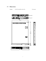
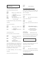
6
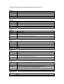
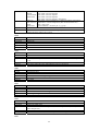
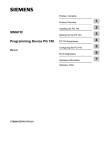
Dimensions
: 431(W) x 44 (H) x 601 (D).
Unit: mm
EC-1018
EC-1017
431
601
Cabinet
29
1.3
481
7
44
2 Installation
The EC-1017/EC-1018 Chassis is very easy to set up for operation. All you have to do
is to open the upper cover, install backplane, your CPU card, display control card,
hard disk drive and other add-on cards required by your application.
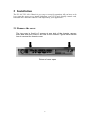
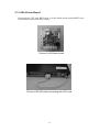
2.1 Remove the cover
The top cover is fixed by 2 screws at rear side of the chassis, remove
them and slide the cover to the rear of the chassis. Figure below shows
how to remove the chassis cover.
Picture of cover open
8
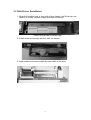
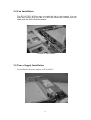
2.2 Disk Drives Installation
1. Open the lockable door at front side of the chassis, the Driver bay has
fixed by 2 screws. Loosen screws and slide out the bay.
Picture of front view of drives cage
2. Install drives into the bay and fix it with the screws.
3. fixed screws and connect cable & power cable to the drive
9
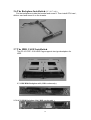
2.3 A106 Alarm Board
Connecting the CPU card RS232 port to A106 Alarm board external RS232 port
for parameter setting from A106 Utility.
Picture of A106 Alarm board
Picture of RS 232 cable connecting with CPU card
10
2.4 Fan Installation
The EC-1017/EC-1018 is easy to install the fan in the chassis. It is not
need any screw. Plug the fan in to the fan holder and connect the fan
cable with the A106 controller board.
Picture of Fan module
2.5 Power Supply Installation
For installation the power supply: ACE-830APU1.
11
2.6 The Backplane Installatio n (EC-1017 only)
Put the backplanes inside the bracket and screw it. Then install CPU card ,
Add-on card and mount it on the chassis.
2.7 The HDD CAGE Installation
The EC-1017/EC-1018 HDD Cage supports two type backplane for
HDD .
2.7.1 IDE HDD Backplane A93 ( BID version only )
2.7.2 SCSI HDD Backplane G06 ( BSD version only )
12
2.8 HDD Installation
The two HDD carriers inside your EC-1017/EC-1018 are used to hold the HDD. In
order to remove and replace a HDD carrier follow these steps.
1. Unlock a drive carrier by releasing the plastic latch, on the right side of each
carrier. Push the latch to the left, while pulling and sliding the drive carrier out
of the chassis using the handle on the front.
2. To replace a drive carrier, push it all the way unto an empty bay of the chassis,
until the latch fixes the drive in place.
2.8.1 Installation IDE HDD
1. Remove a HDD carrier from the chassis as described above.
2. Remove screws on rear of HDD carrier.
3. Connect Drive with HDD carrier rear panel. so that the power and IDE
connectors correspond with the connectors inside the carrier.
4. Carefully push the disk drive in the HDD carrier , Secure rear panel using
screws.
5. Make sure the connectors are firmly seated, secure the HDD drive in with the
flat screws provided, next slide and lock the loaded carrier into the chassis.
2.8.2 Installation SCSI HDD
1. Remove a HDD carrier from the chassis as described above.
2. Place the disk drive in the drive carrier.
3. Secure the HDD drive in with the flat screws provided, next slide and lock the
loaded carrier into the chassis.
13
Appendix A Alarm board user’s manual
Alarm Board User’s Manual
A106
buttons are pressed.
A106 also implements one EEPROM to
store working parameters, so that they
can be re-programmed after shipping.
Those parameters can be easy accessed
via RS232 interface of PC.
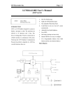
INTRODUCTION
The main function of Alarm Board A106
is to check whether the temperatures in
the chassis and the speed of the fans are
normal. It also via an external
WatchDog timer to monitors user’s
system is working properly or has
dropped halt.
Implementation
A106 comprises the following parts
One A106 Main Board.
Two LEDs with cable and connectors.
One D_Sub 9 pin female cable for
connecting to PC.
One 4-wire cable for connecting LCD
Module.
Two Thermresistor cables with
connectors.
One LCD Module A78 (optional).
One 2-wire cable with switch to turn off
the buzzer.
One 3-wire cable for power
To calculate speed of fans, A106
provides four sets of counter and two
8-bit ADCs (Analog to Digital Converter)
to scan temperature. It also implements
one RS232 WatchDog which contacts
system periodically. Should there be any
abnormality, A106 will alarm the user in
two ways. One is by turning on
Fan/Temp Fail LED and trigger the
buzzer. The other is by passing messages
to system through the RS232 interface,
and also to LCD Module.
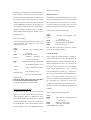
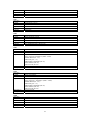
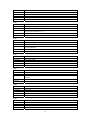
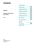
The system block is illustrated in Fig. 1.
Complete the connection and turn on the
power, the two LEDs then blinks for one
second before the fans start running. The
LCD first displays ‘Connecting A106
Ver.01 OK’ for two seconds and then
‘ICP Electronic’ which can be changed
later by users, and thirdly,
Fan/Temperature.
A106 also provides optional functions
such as displaying company banner or
information on LCD, or automatically
increasing fan speed via temperature rising (Auto Mode), passing system
messages for LCD display, and provide
system relevant data like fan speed and
chassis temperature if required, and
actively passing messages if on-board
14
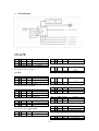
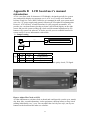
z
Pin Definition
Fig. 1.
On A78
CN1 1 +5V Power
5V power in
2 Rx
In
UART Data In
3 Tx
Out
UART Data Out
4 GND Ground
Ground
**The UART uses 1200 Baud Rate, 8 bit, 1 stop
bit, no parity check, 5V Signal.
JP9 1 LED+
In
2 LED- Out
**Temp Fail LED
Thermresistor Signal
In
2 Tr2 Ground
Ground
**Temperature#0 Sensor
On A106
JP14 1 +5V Power
5V power in
2 Tx
Out
UART Data Out
3 Rx
In
UART Data In
4 GND Ground
Ground
**The UART uses 1200 Baud Rate, 8 bit, 1 stop
bit, no parity check, 5V Signal.
JP15 1 Tx
Out
RS232 Data Out
2 GND Ground
Ground
3 Rx
In
RS232 Data In
**This port uses 1200 Baud Rate, 8 bit, 1 stop
bit, no parity check, ±12V Signal.
In
Out
Tr1
In
JP2 1
Tr1
In
Thermresistor Signal
In
2 Tr2 Ground
Ground
**Temperature#1 Sensor
JP11 1 +5V Power
5V power in
2 Tx
Out
RS232 Data Out
3 Rx
In
RS232 Data In
4 GND Ground
Ground
**This port is reserved for expansion.
JP10 1 LED+
2 LED**Fan Fail LED
JP1 1
LED Anode
LED Cathode
LED Anode
LED Cathode
15
JP5 1 GND Ground
2 +12V Power
3 SG
In
**Fan#0 Connector
Ground
Drive Power
Fan Speed Signal
JP6 1 GND Ground
2 +12V Power
3 SG
In
**Fan#1 Connector
Ground
Drive Power
Fan Speed Signal
JP7 1 GND Ground
2 +12V Power
3 SG
In
**Fan#2 Connector
Ground
Drive Power
Fan Speed Signal
JP8 1 GND Ground
2 +12V Power
Ground
Drive Power
3 SG
In
**Fan#3 Connector
How to Changing Alarm Temperature
Fan Speed Signal
A106 can be easily re-programmed via software.
To set up and receive data from A106, you can
JP13 1 +5V Power
System Power
2 +12V Power
System Power
3 GND Ground
Ground
**System Power Connector
use your familiar serial port communication
tools to work with.
Simply connect A106 to your PC on COM1 with
JP12 1 Sw1 COM Switch Terminal COM
2 Sw2
NO
Switch Terminal NO
**Buzzer Reset Switch, press to shut down the
buzzer for 240 seconds before it resumes the
beep.
Jumper Setting
JP3 1,2 Short
Open
3,4 Short
Open
JP4
1,2
3,4
5,6
7,8
Short
Open
Short
Open
Short
Open
Short
Open
the D-Sub cable, run the communication
program on 1200 baud rate and data format set
on N, 8,1, (do not forget connecting two
temperature sensors and four fans) and turn on
the power supply of A106. Based on the protocol
Disable Temp #0 Alarm
Enable Temp #0 Alarm
Disable Temp #1 Alarm
Enable Temp #1 Alarm
in appendix A, send the following command:
Send to A106: 0x4D 0x22 0x00 0x46
Where:
0x4D
from
Disable Fan#0 Alarm
Enable Fan#0 Alarm
Disable Fan#1 Alarm
Enable Fan#1 Alarm
Disable Fan#2 Alarm
Enable Fan#2 Alarm
Disable Fan#3 Alarm
Enable Fan#3 Alarm
indicates this command comes
the system
‘Set Alarm Temperature’
index Temp #0
alarm temperature set on 70
0x22
0x00
0x46
℃
After this command is sent, A106 stores this
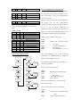
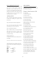
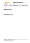
Process Flow Chart of A106
parameter in its EEPROM and will trigger the
Program Entry
Scan Temp. and
Display On LCD
Initialize A106 and
A78 (LCD)
Compare with
Alarm_Temp
buzzer when Temp#0 is over 70℃.
Higher
To double-check the setting, user can send the
Turn On Buzzer,
Send Alarm Message
to LCD and PC
following command:
Lower
A
Display Customer
Banner or
Fan&Temp Status
On LCD
Scan Fans and
Display On LCD
Check
LCD_Serial_Port
(JP21) and
Response
Compare with
Alarm_Fan
Send to A106: 0x4D 0x23 0x00
Where:
0x4D
from
Lower
Turn On Buzzer,
Send Alarm Message
to LCD and PC
0x23
0x00
Higher
Check
PC_Serial_Port
(JP22) And
Response
Watch Dog
Send Polling
Message To PC
the system
‘Get Alarm Temperature’
index Temp#0
After this command is sent, A106 replies the
following message:
No
Check PC
Echoing
indicates this command comes
Turn On Buzzer,
Send Alarm Message
to LCD
Receive from A106: 0x53 0x24 0x00 0x46
Yes
Where:
0x53
from
A
0x24
16
indicates this command comes
A106
‘Report Alarm Temperature’
0x00
0x46
index Temp#0
the current set value
command:
Send to A106: 0x4D 0x26 0x00
The setting of Alarm Te mperature #1 is the
is changed from 0x00 to 0x01.
Where:
0x4D
from
After the setting, A106 senses the temperatures.
0x26
0x00
same as the above, except that the index number
indicates this command comes
the system
‘Get Alarm fan Speed’
index Fan#0
If temperature #0 is higher than the set value,
As soon as this command is sent, A106 replies
A106 first triggers the buzzer, and the Temp Fail
the system with the message,
LED blinks; then the message:
Receive from A106: 0x53 0x27 0x00 0x0F
Warning
T0 Over Heat
Where:
0x53
from
is displayed on LCD before/and the event report
0x27
0x00
0x0F
‘0x53 0x34 0x01’ is passed to the system.
indicates this command comes
A106
‘Report Alarm Fan Speed’
index Fan#0
value stored in A106
A106 then detects the speeds of 4 fans, and if
there is any fan running slower than the set
speed, A106 first triggers the buzzer, and the Fan
Fail LED blinks before the message
Warning
Fan0 Fail
How to Changing Alarm Fan Speed
The procedure of setting Alarm Fan Speed is
is displayed on LCD. The event report ‘0x53
similar to that of setting Alarm Temperature.
0x34 0x02’ is then passed to system warning
Based on the protocol in Appendix A, send the
speed abnormality has taken place.
command:
How to Setting WatchDog
Send to A106: 0x4D 0x25 0x00 0x0F
Where:
0x4D
from
0x25
0x00
0x0F
speed
A106 has implemented a WatchDog function to
insure A106’s access to the system. After
indicates this command comes
WatchDog is enabled, A106 periodically sends
the system
‘Set Alarm Fan Speed’
index Fan#0
trigger A106 alarm if Fan#0
polling message to system and wait for system
echo. If the system fails to reply after WatchDog
sends the message consecutively for 5 times,
lower than 900 RPM (Where
900=0x0F multiply by 60, which 60 is
a
constant
multiplier that A106 internally uses.)
WatchDog assumes that the system has drop halt
and starts the alarming procedure, i.e., triggering
the buzzer, and displaying warning message on
the LCD.
Similarly, to double-check the setting stored in
A106, simply send ‘Get Alarm Fan Speed’
17
Warning
System Holding
Where:
0x00
The setting command is as followed,
How to Displaying Message on LCD
Send to A106: 0x4D 0x12 0x01 0x0A
Besides alarm messages, the LCD Module can
Where:
0x4D
from
0x12
0x01
0x0A
system
also display short messages from the system.
indicates this command comes
Here is an example:
the system
‘Set WatchDog Mode and Time
Interval’
enable WatchDog
send polling messages to the
Send to A106: 0x4D 0x28
Where:
0x28
Where:
0x0D
To double-check the setting, send the following
command:
indicates this command come
the system
‘Get WatchDog Mode and Time
Interval’
Receive from A106: 0x53 0x13 0x01 0x0A
0x13
Time
0x01
0x0A
Where:
0x0C
0x00
line0
‘Display Character on LCD’
the characters displayed on
0x03
(first line on LCD)
indicates that there will three
characters displayed
And the string
0x49 0x43 0x50
A106 then replies with:
Where:
0x53
‘Clear LCD’
Send to A106: 0x4D 0x0C 0x00 0x03 0x49 0x43
0x50
Send to A106: 0x4D 0x2A
0x2A
‘Stop LCD Auto Clock Display’
Send to A106: 0x4D 0x0D
every 10 seconds.
Where:
0x4D
from
disable WatchDog
ASCII codes for ‘ICP’
After the commands are sent, the LCD first stops
the clock and clear the display, then ‘ICP’ is
indicates this command comes
from A106
‘Report WatchDog Mode and
shown on the upper-left corner of LCD like:
ICP
Interval’
WatchDog enabled
time interval set at 10seconds
After setting, WatchDog is been enable and will
If you like to stop this display and return to the
send ‘0x53 0x20’ the Polling Command every
default display, send this command:
10sec, system after receive this command, it
Send to A106: 0x4D 0x29
should reply ‘0x4D 0x21’ the Echo Command to
Where:
0x29
tell WatchDog alive and keep silence.
To disable WatchDog, send the following
‘Start LCD Auto Clock Display’
LCD then retrieves the display from system and
command:
start displaying the clock.
Send to A106: 0x4D 0x12 0x00 0x0A
How Setting your ‘First Display’
18
Auto Control of fans.
First Display command is a little different from
that of ‘Display Character on LCD’ describe in
Manual Control
the last section. The latter displays characters at
The Manual Control applies fixed power to fans
the request of the system and may be cleared
which is separated into 4 levels. Level 0 stands
anytime, while the former stores the contents in
for 5/8 power, Level 1 for 6/8 power, Level 2 for
A106 EEPROM and display the messages on
7/8 power and Level 3 for full power. Users can
LCD regularly. This function is to allow users to
choose the proper level to fit the circumstances.
display permanent messages such as company
Send to A106: 0x4D 0x1D 0x00 0x02
name, machine model and phone number, etc. on
Where:
0x4D
from
the LCD screen.
Here is an example.
0x2E
Now the fans are driven by 7/8 power, and the
indicates this command comes
the system
‘Set First Display Line0’
messages
displayed
noises are accordingly reduced.
Automatic Mode
on
In this mode, one simple formula is applied to
i.e., first line on LCD
time allowed to toggle the display
control the fan power. First, A106 calculates the
the Fan&Temp Data screen
Alarm Temperature. For every 5℃ increase, the
Line0,
0x20
of
the system
‘Set Fan Control Level’
Manual Control (Fixed Mode)
Power set on Level 2
0x1D
0x00
0x02
Send to A106: 0x4D 0x2E 0x20 0x49 0x43 0x50
0x20 0x45 0x6C 0x65 0x63 0x74 0x72 0x6F
0x6E 0x69 0x63 0x20
Where:
0x4D
from
indicates this command come
difference between current temperature and the
(in this
driven power goes up for one level. For example,
case, 32 seconds. If the value
if the Alarm Temperature is 70℃, and the
is zero,
First_Display_Screen
current temperature is below 75℃, the power is
stay on LCD permanently)
set on Level 0. When the current temperature is
messages will
above
and the string:
0x49 0x43 0x50 0x20 0x45 0x6C 0x65 0x63
0x74 0x72 0x6F 0x6E 0x69 0x63 0x20
are the ASCII codes for ‘ICP Electronics’
75℃ but below 80℃, the power is set
on Level 1. Similarly, if the temperature is above
80℃ but below 85℃, the power is set on Level
2. When the temperature goes up above 85℃,
the fans are driven to the full power. Here is an
example.
How to Controlling the Fan
In most cases, the fans are driven to the full
Send to A106: 0x4D 0x1D 0x01 0x00
speed to cool the system. However, there are
Where:
0x4D
from
times when the chassis is installed in cooler
environment, and the fan speed may be lowered
in order to reduce the
indicates this command comes
the system
0x1D
‘Set Fan Control Level’
0x01
A106 set in Auto Mode
whilst 0x00 is only padding.
noises. As a result, A106
has implemented a fan control function with 2
choices offered to users- the Manual Control or
19
How to Adjusting The Clock on LCD
Others commands
The LCD Module A78 has implemented a real
The Peripheral Communication Protocol in
time clock on board which provides the
Appendix A comprise 52 commands which can
information of year, month, day, hour, min,
be separated into 2 groups.
second. It is also equipped with a backup battery
that lasts for more than 3 years. There are 2 ways
Group A: from System to A106
to adjust the clock- one by two buttons on the
Get_ID (0x00)
board and the other via software.
Set_LED_On/Off (0x02)
Get_LED_Status (0x03)
Adjusting by Buttons
Get_Button_Status (0x06)
Step 1: Press the upper button for more than 3
Get_Protocol_Version (0x07)
seconds until a blinking cursor appears on the
Set_Clock_Time (0x09)
LCD screen.
Get_Clock_Time (0x0B)
Display_Character_On_LCD (0x0C)
Step 2: Press the lower button to adjust time.
Clear_LCD (0x0D)
Get_Fan_RPM (0x0E)
Step 3: Press the upper button again to advance
Get_Temperature (0x10)
the blinking cursor to the next position.
Set_WatchDog_Mode_and_Timer (0x12)
Get_watchdog_Status (0x2A)
Step 4: repeat Step 2 and Step 3.
How_Many_Fan (0x14)
Step 5: When the clock is set, press the upper
How_Many_Temperature (0x15)
button again for more than 3 seconds to leave
Set_Fan_Control_Level (0x1D)
Edit Mode, until the cursor disappears and the
Get_Fan_Control_Level (0x1E)
clock starts running.
Echo_WatchDog (0x21)
Software Adjusting via
Set_Alarm_Temperature (0x22)
To adjust the clock on A78 via software, here is
Get_Alarm_Temperature (0x23)
an example.
Set_Alarm_Fan_Speed (0x25)
Get_Alarm_Fan_Speed (0x26)
Stop_LCD_Self_Regular_Display (0x28)
Send to A106: 0x4D 0x09 0x00 0x0C 0x07 0x0D 0x28 0x05
Start_LCD_self_Regular_Display (0x29)
While 0x4D means this command comes from
Set_LCD_Special_Flags (0x2B)
System, 0x09 is the command of ‘Setting Clock
Get_LCD_Special_Flags (0x2C)
Time’.
Set_First_Display_Line0 (0x2E)
And where
0x00
year 2000
0x0C
December
0x07
7th Day
0x0D
13 o’clock
0x28
40 minutes
0x05
5 seconds
Set_First_Display_Line1 (0x2F)
Get_First_Display_Line0_Contents (0x30)
Get_First_Display_Line1_Contents (0x31)
Set_Clock_Adjustment_Mode (0x35)
Get_Clock_Adjustment_Mode (0x36)
Reset (0xFF)
20
Group B: From A106 to System
Watch Dog Function = Disable
Report_ID (0x01)
Watch Dog Timer = 10 sec
Report_LED_Status (0x04)
First Display Line0 = ‘ICP Electronics’
Report_Button_Status (0x05)
First Display Line1 = ‘
’
Report_Protocol_Version (0x08)
Notes
Report_Clock_Time (0x0A)
Due to the limited resource of MCU, please note
Report_Fan_RPM (0x0F)
that:
Report_Temperature (0x11)
Report_WatchDog_Status (0x13)
A. The UART buffer equipped in A106 is only
Report_How_Many_Fan (0x17)
16 bytes. If the system is to send commands
Report_How_Many_Temperature (0x16)
over 16 bytes to A106, the data traffic is
Report_Fan_Control_Level (0x1F)
better to be separated into smaller packages,
WatchDog_Polling (0x20)
each
Report_Alarm_Temperature (0x24)
under 16 bytes, and delays at
intervals are needed to avoid data overflow.
Report_Alarm_Fan_Speed (0x27)
B. A106 only supports the Thermresistors from
Report_LCD_Special_Flags (0x2D)
‘SemiTec company model 103JT-025-3P’.
Report_First_Display_Line0_Contents (0x32)
Therefore, other Thermresistors may not be
Report_First_Display_Line1_Contents (0x33)
suitable for the database built in A106. The
Report_Event (0x34)
LCD can only reflect temperatures from
Report_Clock_Adjustment_Mode (0x37)
10℃ to 99℃. Temperatures below or above
Ack (0xFA)
the range will be truncated to 10℃ or 99℃,
Nack (0xFB)
respectively.
Reset_OK (0xAA)
C. The Fan speed counters on A106 can count
the frequency up to 9,999 RPM, which is
For more details, please refer to examples in
well above the speed of most DC Fans.
Appendix A.
However,it is recommended not to use the
Manufacturer Setting
maximum speed, otherwise, an incorrect
Before shipping, the manufacturer has initialized
count value will be displayed on LCD.
the A106 as the below list in order to fit in most
D. Short circuit of JP3 and JP4 does not
circumstances. However, the device can be
actually disable the detection of Fan and
re-programmed to meet users’ needs.
Temp. Instead, it connects the input to a
dummy signal to replace the original input.
Alarm Temperature #0 = 70℃
As a result, there are two signals generated
Alarm Temperature #1 = 70℃
from A106. One is a fixed 3150RPM clock
Alarm Fan Speed #0 = 900 RPM
to simulate itself as a normal but solid
Alarm Fan Speed #1 = 900 RPM
dummy fan. The other is a fixed resister
Alarm Fan Speed #2 = 900 RPM
(10Kohm), which is treated as a normal
Alarm Fan Speed #3 = 900 RPM
temperature (25℃) signal to A106. Both
Fan Control = Manuel Control (fix Control)
signals detected by A106 will be regarded as
Fan Control Speed = Full Speed
normal, and therefore keep the buzzer off.
21
The ICP Peripheral Communication Protocol Version 0.01
0x00
Direction
Content
Command
Emphasis
Response To
Example
Device → Alm/LCD Board
Get ID
0x4D 0x00
0x4D=’M’; 0x00=Get ID
None
0x4D 0x00
0x01
Direction
Content
Command
Emphasis
Response To
Example
Alm/LCD Board → Device
Report ID
0x53 0x01 0xXX 0xYY
0x53=’S’; 0x04=Report ID; 0xXX, 0xYY=ID;
Get ID
0x53 0x01 0x00 0x4E (Board ID= 0x004E ---A078)
0x02
Direction
Content
Command
Emphasis
Response To
Example
Device → Alm/LCD Board
Set LED On/Off
0x4D 0x02 0xXX 0xYY
0x4D=’S’; 0x02=Set LED On/Off; 0xXXYY=LED on/off,
XXYY<15:0>=LED<15:0>, 1=On, 0=off
None
0x4D 0x02 0x00 0x03 (Set LED0, LED1 On)
0x03
Direction
Content
Command
Emphasis
Response To
Example
Device → Alm/LCD Board
Get LED Status
0x4D 0x03
0x4D=’M’; 0x03=Get LED Status
None
0x4D 0x03
0x04
Direction
Content
Command
Emphasis
Response To
Example
0x05
Direction
Content
Command
Emphasis
Alm/LCD Board → Device
Report LED Status
0x53 0x04 0xXX 0xYY
0x53=’S’; 0x04=Report LED status; 0xXXYY=LED on/off
XXYY<15:0>=LED<15:0>, 1=On, 0=Off
Get LED Status
0x53 0x04 0x00 0x0F (LED<3:0> is On)
Response To
Example
Alm/LCD Board → Device
Report Button Status
0x53 0x05 0xXX 0xYY
0x53=’S’; 0x05=Report Button status; 0xXXYY=Buttons on/off
XXYY<15:0>=Button<15:0>, 1=Pressed, 0=Release
Get Button Status
0x53 0x05 0x00 0x80 (Sw7 is On)
0x06
Direction
Content
Device → Alm/LCD Board
Get Button Status
Command
Emphasis
Response To
Example
0x4D 0x06
0x4D=’M’; 0x06=Get Button Status
None
0x4D 0x06
0x07
Direction
Content
Command
Emphasis
Response To
Example
Device → Alm/LCD Board
Get Protocol version
0x4D 0x07
0x4D=’M’; 0x07=Get Protocol Version
None
0x4D 0x07
0x08
Direction
Content
Command
Emphasis
Response To
Example
Alm/LCD Board → Device
Report Protocol version
0x53 0x08 0xXX 0xYY
0x53=’S’; 0x08=Report Protocol Version; 0xXX=Class; 0xYY=version (00~FF)
Get Protocol Version
0x53 0x08 0x00 0x01 (Version 01)
0x09
Direction
Content
Command
Emphasis
Response To
Example
0x0A
Direction
Content
Command
Emphasis
Device → Alm/LCD Board
Set Clock Time
0x4D 0x09 0xYY 0xMM 0xDD 0xHH 0xmm 0xSS
0x4D=’M’; 0x09=Set Clock Time;
0xYY=Year (00~99) Map to (2000 ~ 2099)
0xMM=Month (01 ~ 12)
0xDD=Day (01 ~ 31)
0xHH=Hour 24Hr Mode (00~23)
0xmm=Minute (00~59)
0xSS=Second (00~59)
None
0x4D 0x09 0x00 0x0C 0x07 0x0D 0x28 0x05
(Set Time on 2000/12/07 13:40:05)
Response To
Example
Alm/LCD Board → Device
Report Clock Time
0x53 0x0A 0xYY 0xMM 0xDD 0xHH 0xmm 0xSS
0x53=’S’; 0x0A=Report Clock Time;
0xYY=Year (00 ~ 99) Map to (2000 ~ 2099)
0xMM=Month (01 ~ 12)
0xDD=Day (01 ~ 31)
0xHH=Hour 24Hr Mode (00~23)
0xmm=Minute (00~59)
0xSS=Second (00~59)
Get Clock Time
0x53 0x0A 0x00 0x0C 0x07 0x0D 0x28 0x09 (Report Time 2000/12/07 13:40:09)
0x0B
Direction
Content
Command
Emphasis
Response To
Example
Device → Alm/LCD Board
Get Clock Time
0x4D 0x0B
0x4D=’M’; 0x0B=Get Clock Time
None
0x4D 0x0B
23
0x0C
Direction
Content
Command
Emphasis
Response To
Example
Device → Alm/LCD Board
Display Character on LCD
0x4D 0x0C 0x0L 0x0N 0xXX1 ~ 0xXX15
0x4D=’M’; 0x0C=Display Character On LCD; 0x0L=0x00 (Line 0), 0x0L=0x01
(Line 1); 0x0N=N Character (1~15), Note: no more than 15 characters;
0xXXn=ASCII Codes of Characters,
None
0x4D 0x0C 0x01 0x03 0x49 0x43 0x50 (Line 1, 3 Characters, ‘ICP’)
0x0D
Direction
Content
Command
Emphasis
Response To
Example
Device → Alm/LCD Board
Clear LCD
0x4D 0x0D
0x4D=’M’; 0x0D=Clear LCD
None
0x4D 0x0D
0x0E
Direction
Content
Command
Emphasis
Response To
Example
Device → Alm Board
Get Fan#N RPM
0x4D 0x0E 0x0N
0x4D=’M’; 0x0E=Get Fan#N RPM; 0x0N=Fan#N (0~15)
None
0x4D 0x0E 0x02 (Get Fan2 PRM)
0x0F
Direction
Content
Command
Emphasis
Response To
Example
Alm Board →Device
Report Fan#N RPM
0x53 0x0F 0x0N 0xRR
0x53= ’; 0x0F=Report Fan#N RPM; 0x0N=Fan#N (0~15); 0xRR=RPM/60
Get Fan#N RPM
0x53 0x0F 0x02 0x37 (Fan2=0x37 x 60=3300 rpm)
0x10
Direction
Content
Command
Emphasis
Response To
Example
Device → Alm Board
Get Temperature#N
0x4D 0x10 0x0N
0x4D=’M’; 0x10=Get Temperature#N; 0x0N=Temperature#N (0~15);
None
0x4D 0x10 0x03 (Get Temperature3)
0x11
Direction
Content
Command
Emphasis
Response To
Example
Alm Board →Device
Report Temperature#N
0x53 0x11 0x0N 0xTT
0x53=’S’; 0x11=Report Temp#N;
0x0N=Temp#N (N=0~15);
0xTT=0 ~ 99 ℃
Get Temperature#N
0x53 0x11 0x03 0x1B (Temperature 3 is 27℃)
0x12
Direction
Content
Command
Device → Alm Board
Set WatchDog Mode and Timer
0x4D 0x12 0x0X 0xNN
24
Emphasis
Response To
Example
0x13
Direction
Content
Command
Emphasis
0x4D=’M’; 0x12=Set WatchDog Mode and Timer; 0x0X=Control Mode,
0x00=Watch Dog Off, 0x01=On; 0xNN=Timer (1..180 sec)
None
0x4D 0x12 0x01 0xB4(Enable WatchDog, Timer=180 sec)
0x4D 0x12 0x00 0x64(Disable WatchDog, Timer=100 sec)
Response To
Example
Alm Board →Device
Report WatchDog Status
0x53 0x13 0x0X 0xNN
0x53=’S’; 0x13=Report WatchDog Status; 0x0X=Control Mode; 0xNN=WatchDog
Timer Set.
Get WatchDog Status
0x53 0x13 0x01 0x0A (WatchDog Enabled, WatchDog Timer=10sec)
0x14
Direction
Content
Command
Emphasis
Response To
Example
Device → Alm Board
How Many Fans
0x4D 0x14
0x4D=’M’; 0x14=How Many Fans?
None
0x4D 0x14
0x15
Direction
Content
Command
Emphasis
Response To
Example
Device → Alm Board
How many Temperatures
0x4D 0x15
0x4D=’M’; 0x15=How Many Temperatures?
None
0x4D 0x15
0x16
Direction
Content
Command
Emphasis
Response To
Example
Alm Board →Device
Report how many Temperatures
0x53 0x16 0xXX
0x53=’S’; 0x16=Report How many Temperatures; 0xXX=# of Temperature (1~16);
How many Temperatures
0x53 0x16 0x02 (2 Temperatures)
0x17
Direction
Content
Command
Emphasis
Response To
Example
Alm Board →Device
Report How Many Fans
0x53 0x17 0xXX
0x53=’S’; 0x17=Report How many Fans; 0xXX=# of Fan (1~16);
How many Fans
0x53 0x1B 0x04 (4 Fans here)
0x1D
Direction
Content
Command
Emphasis
Device → Alm Board
Set Fan Control Level
0x4D 0x1D 0x0X 0x0L
0x4D=’M’; 0x1D=Set Fan Speed Level; 0x0X=Control Mode;0x0L=Manual Control
Level.
25
Where in
Manuel
Control Mode
0x0X=0x00
Response To
Example
0x1E
Direction
Content
Command
Emphasis
Response To
Example
0x1F
Direction
Content
Command
Emphasis
0x0X=0x00=Manuel Control,
0x0L=0x00=Level 00=Speed 0
0x0L=0x01=Level 01=Speed 1
0x0L=0x02=Level 02=Speed 2
0x0L=0x03=Level 03=Speed 3=Full Speed
0x0X=0x01=Auto Temperature Control Fan Control, The Control
Temperature = Alarm Temperature (Ref. Command 0x22 set)
0x0L = Don’t care
Control Method = one level per 5℃increase
Where in
Auto Control
Mode
0x0X=0x01
None
0x4D 0x1D 0x00 0x03 (Manual Control, Full Speed)
0x4D 0x1D 0x01 0x00 (Auto Control)
Device → Alm Board
Get Fan Control level
0x4D 0x1E
0x4D=’M’; 0x1E=Get Fan Control Level
None
0x4D 0x1E
Response To
Example
Alm Board →Device
Report Fan Control level
0x53 0x1F 0x0C 0x0L
0x53=’S’; 0x1F=Report Fan Control Level; 0x0C, 0x0L same as Set Fan Speed
Level
Get Fan Control Level
0x53 0x1F 0x00 0x03 (Fan under Manual Control, Full Speed)
0x20
Direction
Content
Command
Emphasis
Response To
Example
Alm Board →Device
WatchDog Polling
0x53 0x20
0x53=’S’; 0x20=WatchDog Polling;
None
0x53 0x20
0x21
Direction
Content
Command
Emphasis
Response To
Example
Device → Alm Board
Echo WatchDog
0x4D 0x21
0x4D=’M’; 0x21=Echo WatchDog;
WatchDog Polling
0x4D 0x21
0x22
Direction
Content
Command
Emphasis
Response To
Example
Device → Alm Board
Set Alarm Temperature
0x4D 0x22 0x0N 0xTT
0x4D=’M’; 0x22=Set Alarm Temperature; 0x0N: Temperature N (N=0..F); 0xTT :
Alarm Temperature;
None
0x4D 0x22 0x01 0x1E ( Set Alarm Temperature 1 on 30℃)
0x23
26
Direction
Content
Command
Emphasis
Response To
Example
0x24
Direction
Content
Command
Emphasis
Response To
Example
0x25
Direction
Content
Command
Emphasis
Device → Alm Board
Get Alarm Temperature
0x4D 0x23 0x0N
0x4D=’M’; 0x23=Get Alarm Temperature; 0x0N: Temperature N
None
0x4D 0x23 0x00 (Get Alarm Temperature 0)
Alm Board →Device
Report Alarm Temperature
0x53 0x24 0x0N 0xTT
0x53=’S’; 0x24=Report Alarm Temperature; 0x0N: Alarm Temperature N (0..F);
0xTT Alarm Temperature. In ℃.
Read Alarm Temperature
0x53 0x24 0x01 0x1E (Report Alarm Temperature 1 set)
Response To
Example
Device → Alm Board
Set Alarm Fan Speed
0x4D 0x25 0x0N 0xRR
0x4D=’M’; 0x25=Set Alarm Fan Speed; 0x0N: Fan N(N=0..F); 0xRR: Alarm Fan
Speed, in RPM/60
None
0x4D 0x25 0x00 0x0F (Set Fan 0 Alarm Speed at 0x0Fx60=900 RPM)
0x26
Direction
Content
Command
Emphasis
Response To
Example
Device → Alm Board
Get Alarm Fan Speed
0x4D 0x26 0x0N
0x4D=’M’; 0x26=Get Alarm Fan Speed; 0x0N: Fan N
None
0x4D 0x26 0x03 (Get Fan3 Alarm Speed set)
0x27
Direction
Content
Command
Emphasis
Response To
Example
Alm Board →Device
Report Alarm Fan Speed
0x53 0x27 0x0N 0xRR
0x53=’S’; 0x27=Report Alarm Fan Speed; 0x0N: Fan N; 0xRR Alarm Fan Speed In
RPM/60.
Read Alarm Fan Speed
0x53 0x27 0x01 0x0F (Report Alarm Fan 1 Speed set at 0x0F×60 = 900RPM )
0x28
Direction
Content
Command
Emphasis
Response To
Example
Device → Alm/LCD Board
Stop LCD Auto Clock Display
0x4D 0x28
0x4D=’M’; 0x28=Stop LCD Auto Clock Display;
None
0x4D 0x28 (Stop LCD Auto Clock Display)
0x29
Direction
Content
Command
Emphasis
Response To
Device → Alm/LCD Board
Start LCD Auto Clock Display
0x4D 0x29
0x4D=’M’; 0x29=Start LCD Auto Clock Display
None
27
Example
0x4D 0x29 (Start LCD Auto Clock Display)
0x2A
Direction
Content
Command
Emphasis
Response To
Example
Device → Alm Board
Get WatchDog Status
0x4D 0x2A
0x4D=’M’; 0x2A=Get WatchDog Status
None
0x4D 0x2A
0x2B
Direction
Content
Command
Emphasis
Response To
Example
Device → Alm/LCD Board
Set LCD Special Flags
0x4D 0x2B 0xXX
0x4D=’M’; 0x2B=Set LCD Special Flags; 0xXX=Flags,
X0= 1:Turn On Watch_Dog_Flag Display on LCD
0:Turn Off Watch_Dog_Flag Display on LCD
X1..7 Reserved
None
0x4D 0x2B 0x01 : Turn On Watch_Dog_Flag Display
0x2C
Direction
Content
Command
Emphasis
Response To
Example
Device →Alm/LCD Board
Get LCD Special Flags
0x4D 0x2C
0x4D=’M’; 0x2C=Get LCD Special Flags
None
0x4D 0x2C
0x2D
Direction
Content
Command
Emphasis
Response To
Example
Alm/LCD Board → Device
Report LCD Special Flags
0x53 0x2D 0xXX
0x53=’S’; 0x2D=Report LCD Special Flags; 0xXX=Flags
Get LCD Special Flags
0x53 0x2D 0x01 : Watch_Dog_Flag display turned on.
0x2E
Direction
Content
Command
Emphasis
Response To
Example
0x2F
Direction
Content
Command
Emphasis
Device →Alm Board
Set First Display Line0
0x4D 0x2E 0xTT 0xXX0..0xXX15
0x4D=’M’; 0x2E=Set First Display Line0, This string is given first priority to
display and the contents are stored in EEPROM;
0xTT=Time to toggle to Second Display Screen, ranging from 0sec to 255sec;
0sec indicates no toggling. Second Display Screen regularly displays
Fan and Temperature Messages from Alarm Board.
0xXXx=Characters in ASCII codes, fixed size: 15 characters.
None
0x4D 0x2E 0x20 0x49 0x43 0x50 0x20 0x45 0x6c 0x65 0x63 0x74 0x72 0x6f 0x6e
0x69 0x63 0x20 ( First display ‘ICP Electronics’ on Line0, and 32sec toggle to
release display )
Device → Alm Board
Set First Display Line1
0x4D 0x2F 0x00 0xXX0..0xXX15
0x4D=’M’; 0x2F=Set First Display Line1, This string is given first priority to
28
Response To
Example
display and the contents are stored in EEPROM;
0x00 =Constant.
0xXXx=Characters in ASCII codes, fixed size: 15 characters.
None
0x4D 0x2F 0x20 0x49 0x43 0x50 0x20 0x45 0x6c 0x65 0x63 0x74 0x72 0x6f 0x6e
0x69 0x63 0x20 ( First display ‘ICP Electronic’ on Line1 and 32sec toggle to release
display )
0x30
Direction
Content
Command
Emphasis
Response To
Example
Device → Alm/LCD Board
Get First Display Line0 Contents
0x4D 0x30
0x4D=’M’; 0x30=Get First Display Line0 Contents
None
0x4D 0x30
0x31
Direction
Content
Command
Emphasis
Response To
Example
Device → Alm/LCD Board
Get First Display Line1 Contents
0x4D 0x31
0x4D=’M’; 0x31=Get First Display Line1 Contents
None
0x4D 0x31
0x32
Direction
Content
Command
Emphasis
Response To
Example
0x33
Direction
Content
Command
Emphasis
Response To
Example
0x34
Direction
Content
Command
Emphasis
Alm/LCD Board →Device
Report First Display Line0 Contents
0x53 0x32 0xTT 0xCC0..0xCC15
0x53=’S’; 0x32=Report First Display Line0 Contents
Get First Display Line0 Contents
0x53 0x32 0x0A 0x49 0x43 0x50 0x20 0x41 0x63 0x71 0x75 0x69 0x72 0x65 0x20
0x49 0x6E 0x63: ( Report the contents of First Display is ‘ICP Acquire Inc’ on Line0
and the toggle time is 10 sec.)
Alm/LCD Board →Device
Report First Display Line1 Contents
0x53 0x33 0xTT 0xCC0..0xCC15
0x53=’S’; 0x33=Report First Display Line1 Contents
Get First Display Line0 Contents
0x53 0x33 0x0A 0x49 0x43 0x50 0x20 0x41 0x63 0x71 0x75 0x69 0x72 0x65 0x20
0x49 0x6E 0x63 ( Report the contents of First Display is ‘ICP Acquire Inc’ on
Line1, and the toggle time is 10 sec.)
Response To
Example
Alm Board →Device
Report Event
0x53 0x34 0xNN
0x53=’S’; 0x34=Report Event
0xNN
=0x01, Over Heat
=0x02, Fan Fail
None
0x53 0x34 0x01 (Report Event - Over Heat)
0x35
Direction
Content
Device → Alm/LCD Board
Set Clock Adjustment Mode
29
Command
Emphasis
Response To
Example
0x4D 0x35 0xNN
0x4D=’M’; 0x35=Set Clock Adjustment Mode;
0xNN
=0x00, Disable Manual Adjustment
=0x01, Enable Manual Adjustment
None
0x4D 0x35 0x01 Enable Clock Manual Adjustment
0x36
Direction
Content
Command
Emphasis
Response To
Example
Device → Alm/LCD Board
Get Clock Adjustment Mode
0x4D 0x36
0x4D=’M’; 0x36=Get Clock Adjustment Mode
None
0x4D 0x36
0x37
Direction
Content
Command
Emphasis
Response To
Example
Alm/LCD Board →Device
Report Clock Adjustment Mode
0x53 0x37 0xNN
0x53=’S’; 0x37=Report Clock Adjustment Mode
0xNN
=0x00, Disable Manual Adjustment
=0x01, Enable Manual Adjustment
Get Clock Adjustment Mode
0x53 0x37 0x00 (Manual Adjustment disabled)
0xFA
Direction
Content
Command
Emphasis
Response To
Example
LCD/LED/Alarm Board →Device
Ack
0x53 0xFA
0x53=’S’; 0xFA=Ack;
N/A
0x53 0xFA
0xFB
Direction
Content
Command
Emphasis
Response To
Example
LCD/LED/Alarm Board → Device
Negative Ack
0x53 0xFB 0xCC
0x53=’S’; 0xFB=Negative Ack; 0xCC Command;
N/A
0x53 0xFB 0xF0 (NAK 0xF0 Command)
0xFF
Direction
Content
Command
Emphasis
Response To
Example
Device → Alm Board
Reset
0x4D 0xFF
0x4D=’M’; 0xFF=Reset Slave Device
None
0x4D 0xFF
0xAA
Direction
Content
Command
Emphasis
Response To
Example
LCD/LED/Alarm Board → Device
Reset OK
0x53 0xAA
0x53=’S’; 0xAA=Reset OK;
Reset
0x53 0xAA
30
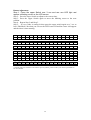
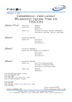
Appendix B
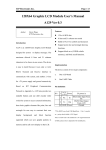
LCD board user’s manual
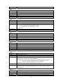
Introduction
A78 is a two lines with 20 characters LCD Module, designed specially for system
easy and quickly display text message over it, A78 is very easily to be installed
because it only use 2 wire RS232 interface to communicate with your system and 2
wires for +5V power supply and ground, following ICP Peripheral Communication
Protocol , A78 will have versatile functions for your program, meanwhile, A78
provide you a on board battery backup real time clock default display on the right
corner and provide system reading, the clock could be manual adjustment by two
buttons or by system via software, A78 also provide you two readable buttons for
system easily to access information with outside.
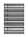
z Jumper setting
(b)
CN1
A78 (a)
A78
Power
1 +5V
Power
5V power in
CN 2 Rx
In
UART Data In
1 3
Tx
Out
UART Data Out
4 GND Ground
Ground
The UART use 1200 Baud Rate and 8 bit, 1 stop bit, none parity check, 5V Signal.
How to Adjust The Clock on LCD
A78 has implement a real time clock on board and could provide you the year, month,
day, hour, min, second information, it also equipment a backup battery to keep clock
running individually over 3 year. You can adjust the clock by two ways, one by two
buttons on the board and the other use software.
31
Button Adjustment
Step 1: Press the upper Switch over 3 sec and see one LED light and
appear a blinking cursor on the LCD screen.
Step 2: Press the lower Switch to adjust to the correct time.
Step 3: Press the Upper Switch again to move the blinking cursor to the next
position.
Step 4: Repeat Step 2 and Step 3.
Step 5: If every value is setting ok then press the upper switch again over 3 sec to
leave Edit Mode, after that you can see the LED is turn off and the cursor is disappear
and the timer is start running.
!
“
#
$
%
&
‘
(
)
*
+
,
.
/
0x20 0x21 0x22 0x23 0x24 0x25 0x26 0x27 0x28 0x29 0x2A 0x2B 0x2C 0x2D 0x2E 0x2F
0
1
2
3
4
5
6
7
8
9
:
;
<
=
>
?
0x30 0x31 0x32 0x33 0x34 0x35 0x36 0x37 0x38 0x39 0x3A 0x3B 0x3C 0x3D 0x3E 0x3F
@
A
B
C
D
E
F
G
H
I
J
K
L
M
N
O
0x40 0x41 0x42 0x43 0x44 0x45 0x46 0x47 0x48 0x49 0x4A 0x4B 0x4C 0x4D 0x4E 0x4F
P
Q
R
S
T
U
V
W
X
Y
Z
[
¥
]
^
_
0x50 0x51 0x52 0x53 0x54 0x55 0x56 0x57 0x58 0x59 0x5A 0x5B 0x5C 0x5D 0x5E 0x5F
`
a
b
c
d
e
f
g
h
i
j
k
l
m
n
o
0x60 0x61 0x62 0x63 0x64 0x65 0x66 0x67 0x68 0x69 0x6A 0x6B 0x6C 0x6D 0x6E 0x6F
p
q
r
s
t
u
v
w
x
y
z
{
|
}
→
←
0x70 0x71 0x72 0x73 0x74 0x75 0x76 0x77 0x78 0x79 0x7A 0x7B 0x7C 0x7D 0x7E 0x7F
**ASCII codes over 0x80 are reserved for special symbols, please contact your sales representatives
for more details.
32
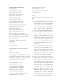
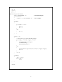
Appendix C Watchdog
This program here demonstrates the function of WatchDog and how it is enabled by
software as well as how the software echoes the WatchDog and keeps the buzzer off.
Initial COM Port 1
InitUart()
Send { 0x4D 0x12 0x01 0x03 } to
Enable WatchDog
SendCommand(cmd1, 4)
Check COM1 Receive Buffer
Yes
No
Buffer =0x53 0x20 ?
Yes
Send {0x4D 0x21} to Echo
WatchDog
SendCommand(cmd2, 2)
33
{
***************************************************************************
*
Program : WatchDog Demo Program
*
*
Operation System : IBM PC, DOS 3.1 or above
*
*
Compiler : BCC 5.0 or above
*
*
File name : WDSAMP.CPP
*
*
Author : Ethan Wang in ICP
*
*
Date : 01/04/2001
*
*************************************************************************** }
#include <dos.h>
#include <stdio.h>
#include <conio.h>
#define IOBASE
0x3f8
// data bits = 8, stop bit = 1, no parity bit, baud rate = 1200
void InitUART()
{
// Set baud rate to 1200
outport(IOBASE + 3, 0x80);
// Line Control Register
outport(IOBASE + 0, 96);
// Divisor Latch Low
outport(IOBASE + 1, 0);
// Divisor Latch High
// Set data bits, stop bit and parity bit.
outport(IOBASE + 3, 0x03);
}
// Send command to Alarm Board
void SendCommand(char *cmd, int len)
{
unsigned char status;
for (int i = 0 ; i < len ; )
{
status = inport(IOBASE + 5);
// Line Status Register
if ( status & 0x20 )
// Transmit-hold-register empty
{
outport(IOBASE + 0, cmd[i]);
// Send to "Transmit Buffer"
i++;
}
}
}
int main()
{
char cmd1[] = { 0x4d, 0x12, 0x01, 0x03 };
// Enable WatchDog with Timeout = 3 sec
char cmd2[] = { 0x4d, 0x21 };
// Echo WatchDog
char rxbuf[20];
// Buffer to receive data from alarm board
int nrx;
// How many bytes we had read
int sync;
// Used to delimit reply code
unsigned char status;
// Serial Port Initialization
InitUART();
// Enable WatchDog
printf("Enable WatchDog\n");
34
SendCommand(cmd1, 4);
nrx = 0;
sync = 1;
for ( ; ; )
{
// Receive data from Alarm Board
status = inport(IOBASE + 5);
if ( status & 0x01 )
{
rxbuf[nrx++] = inport(IOBASE + 0);
}
// Line Status Register
// Receive Buffer
if ( !sync )
{
if ( rxbuf[0] == 0x53 )
{
sync = 1;
nrx = 1;
}
else
{
nrx = 0;
}
}
if ( nrx == 2 )
{
// Check if the reply code is "WatchDog Polling"
if ( rxbuf[0] == 0x53 && rxbuf[1] == 0x20 )
{
printf("WatchDog is polling\n");
// Echo WatchDog
SendCommand(cmd2, 2);
}
else
{
printf("Unknown reply code (%02x, %02x)\n", rxbuf[0], rxbuf[1]);
sync = 0;
}
nrx = 0;
}
if ( kbhit() )
{
char c = getch();
if ( c == 'q' )
break;
}
}
return 0;
}
35
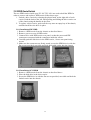
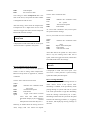
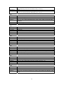
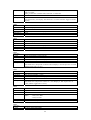
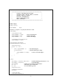
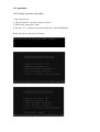
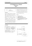
A-3 operation
A106 utility operation procedure
1. Type alm_utl.exe
2. Choice which PC com port connect to A106
3. Edit item to setting your value
4. Execute “ F3 “ function key to download data to A106 EEPROM
Below are process picture for reference
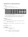
Appendix D Power supply Specifications
AC INPUT :
VOLTAGE : 90V ~ 264V (47 ~ 63Hz)
CURRENT : 5.0A (MAX.AT 100V AC INPUT. FULL LOAD )
DC OUTPUT :
OUTPUT
V1
V2
VOLTAGE
+3.3 V
+5 V
MIN. LOAD
0A
0.5A
** MAX. LOAD
*20 A
*28A
PEAK LOAD.
25A
40A
***REGULATION
+5/-4%
±5%
RIPPLE & NOISE (MAX.)
50mV
50mV
*+3.3V & +5V OUTPUT MAXIMUM 140 WATTS.
V3
+12 V
0.5 A
16A
20A
±5%
120mV
V4
-5 V
0A
V5
-12 V
0A
V6
+5 Vsb
0A
0.5 A
1A
2A
±5%
50mV
+8/-5%
120mV
±5%
50mV
** TOTAL OUTPUT MAXIMUM 300 WATTS.
*** THE OUTPUT VOLTAGE LOAD REGULATION IS LESS THAN THE VALUES IN
THE ABOVE TABLE BY CHANGING EACH OUTPUT LOAD ±40% FROM 60% OF
RATED LOAD, A ND KEEP ALL OTHER OUTPUTS AT 60% OF RATED LOAD.
DIMENSION :
83(W) × 270(D) × 40.5(H) mm
SAFETY : Meet UL 60950, CSA C22.2 NO.60950, TUV EN 60950, IEC 60950,
EMKO-TSE (74-SEC) 207/94
EMI : Meet FCC CFR 47 PART 15 SUBPART J , CLASS B LIMIT, EN 50081-1, CNS 13438
CLASS B.
EMS : EN 50082-1, EN 61000-4-2
ENVIRONMENT :
1. TEMPERATURE : OPERATING : 0 ~ 70℃
STORAGE : -10 ~ +75 ℃
2. HUMIDITY : OPERATION 20% ~ 85% RH. (NON CONDENSING)
STORAGE 10% ~ 95%RH. (NON CONDENSING)
37