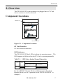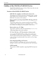
1
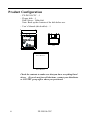
FX-DS110-CFC
FLEXLAN-DS110 Series CF Card
User’s Guide
Copyright
Copyright 2002 CONTEC Co., LTD. ALL RIGHTS RESERVED
No part of this document may be copied or reproduced in any form
by any means without prior written consent of CONTEC Co., LTD.
CONTEC Co., LTD. makes no commitment to update or keep
current the information contained in this document.
The information in this document is subject to change without
notice.
All relevant issues have been considered in the preparation of this
document. Should you notice an omission or any questionable
item in this document, please feel free to notify
CONTEC Co., LTD.
Regardless of the foregoing statement, CONTEC assumes no
responsibility for any errors that may appear in this document nor
for results obtained by the user as a result of using this product.
Trademarks
MS, Microsoft, Windows, Windows NT, and MS-DOS are
registered trademarks or trademarks of Microsoft Corporation in the
U.S.A. and other countries.
Netscape Navigator is a registered trademark of Netscape
Communications.
Other names of companies and products used in this document
trademarks or registered trademarks of the related companies.
This document does not use the symbols ™, ®, © etc.
FX-DS110-CFC
i
Product Configuration
- FX-DS110-CFC …1
- Floppy disk …1
Disk: driver - UtilitySoft
Note: Back up the contents of the disk before use.
- User’s Manual (this booklet)…1
Disk
WIRELE SS LA N CA RD
FX-DS110-CFC
User’s Manual
User’s Manual
Check the contents to make sure that you have everything listed
above. If you do not have all the items, contact your distributor
or CONTEC group office where you purchased.
ii
FX-DS110-CFC
Table of Contents
Copyright ........................................................................... i
Trademarks........................................................................ i
Product Configuration...................................................... ii
1. Introduction ............................................................. 1
Features.........................................................................1
Terminology/Abbreviations...........................................2
Limited One-Year Warranty .........................................3
How to Obtain Service ..................................................3
Liability .........................................................................3
Handling Precautions ...................................................4
Precautions for Use .......................................................4
Notes on Radio Interference .........................................5
About the Manual .........................................................6
2. Overview .................................................................. 7
Component Locations....................................................... 7
Outline of the FLEXLAN-DS110 Series.......................... 8
Features of the FLEXLAN-DS110 Series ....................8
Production Introduction to the FLEXLAN-DS110
Series .............................................................................9
3. Installation of a Hardware ........................................ 11
Plugging the FX-DS110-CFC..........................................11
Unplugging the FX-DS110-CFC .................................... 12
Windows 95, Windows 98, Windows Me,
Windows 2000..............................................................12
Windows XP.................................................................12
Installation in a Network............................................... 13
Features of the Wireless Network..............................13
Operating Environment and Radio Waves ................14
Constructing a Network .............................................15
Operation of the FLEXLAN-DS110............................17
FX-DS110-CFC
iii
4. Installation of a Driver ............................................. 19
Driver Software .............................................................. 19
Installing for Windows Me............................................. 20
Installing for Windows 98 .............................................. 21
Installing for Windows 95 .............................................. 22
Installing for Windows 2000 .......................................... 24
Installing for Windows XP ............................................. 24
Installing for Windows NT............................................. 25
Installing for H/PC ......................................................... 26
Uninstallation of Hardware........................................... 27
Uninstalling the Driver in Windows Me/98/95..........27
Uninstalling the Driver in Windows 2000 .................27
Uninstalling the Driver in Windows XP ....................28
Uninstalling the Driver in Windows NT....................28
5. Using and Setting up the Utility Software .................. 29
Installing and Uninstalling the Utility Software ......... 29
Installation ..................................................................29
Uninstallation .............................................................30
Using and Setting Up the Utility Software .................. 31
Task Bar Icons.............................................................31
Communication Settings ............................................32
RSSI Indicating the Signal Strength of a Radio
Station .........................................................................33
Editing the Name of a Radio Station .........................34
6. Troubleshooting ....................................................... 35
Cannot Detect the LAN Card Automatically ................ 35
When Communication Fails .......................................... 37
7. Appendix ................................................................. 39
Product Specifications.................................................... 39
Glossary .......................................................................... 40
iv
FX-DS110-CFC
List of Figures
Figure 2.1.
Component Locations ...............................................7
Figure 2.2.
User Unit...................................................................9
Figure 2.3.
Access Point..............................................................9
Figure 2.4.
Micro Access Point .................................................10
Figure 3.1.
Infrastructure Mode.................................................17
Figure 3.2.
ADHOC Mode ........................................................18
List of Tables
Table 2.1.
LED States during Normal Operation ..........................7
Table 5.1. Task Bar Icons ...........................................................31
Table 5.2.
Main Communication Settings...................................32
Table 7.1.
FX-DS110-CFC.........................................................39
FX-DS110-CFC
v
vi
FX-DS110-CFC
Introduction
1. Introduction
Thank you for purchasing the FLEXLAN-DS110series
CompcactFrash Card(CF Card) FX-DS110-CFC.
This product is a wireless LAN CF card that operates in the 2.4
GHz band using direct sequence spread spectrum (DSSS). It
complies with the IEEE 802.11B wireless LAN standard and can
use 1 to 11 or 13 channels.
This document explains how to use the FX-DS110-CFC. Be sure to
read it carefully so that you can use the product correctly.
Features
IEEE 802.11b compliant wireless LAN in the 2.4 GHz band
This product is a wireless LAN card using the 2.4 GHz band,
requiring no license for use.
The product complies with the IEEE 802.11b wireless LAN
standard.
Providing a wireless network environment
The product can connect your PC to the LAN without cabling. It
provides a mobile environment even for a battery-powered device
such as a notebook PC while reducing the wiring cost.
Providing transmission in the 2.4 GHz band using direct
sequence spread spectrum (DSSS)
Spread spectrum makes it very difficult to perform radio tapping,
compared to other general radio communication systems. It also
has a characteristic of being highly immune to electromagnetic
interference.
Data transfer rate of 11 Mbps
The product switches its data rate automatically to 11, 5.5, 2, or
1Mbps depending on the radio conditions.
FX-DS110-CFC
1
Introduction
Offering up to 11 or 13 channels available
As the Wireless Telegraphy Act was amended, the frequency band
available to wireless LAN was widened and maximum number of
channels available increased to 11(FCC model) or 13(CE model).
Using different channels for adjacent wireless networks prevents
radio interference, thereby improving the throughputs of the
network.
Capable of inter-channel roaming
PC Card (TYPE II) compliant interface
Capable of constructing a network only with the
FX-DS110-CFC
You can use multiple FX-DS110-CFC cards to construct a Peer-toPeer ad hoc network.
Terminology/Abbreviations
The following terms and abbreviations are used in this manual for
convenience.
Full term
Term used in this manual
FX-DS110-APE
Access point/AP
A device with the wireless function
User unit/
Wireless terminal
Personal computer
2
PC
FX-DS110-CFC
Introduction
Limited One-Year Warranty
CONTEC Interface boards are warranted by CONTEC Co., LTD. to
be free from defects in material and workmanship for up to one year
from the date of purchase by the original purchaser.
Repair will be free of charge only when this device is returned
freight prepaid with a copy of the original invoice and a Return
Merchandise Authorization to the distributor or the CONTEC group
office, from which it was purchased.
This warranty is not applicable for scratches or normal wear, but
only for the electronic circuitry and original boards. The warranty
is not applicable if the device has been tampered with or damaged
through abuse, mistreatment, neglect, or unreasonable use, or if the
original invoice is not included, in which case repairs will be
considered beyond the warranty policy.
How to Obtain Service
For replacement or repair, return the device freight prepaid, with a
copy of the original invoice. Please obtain a Return Merchandise
Authorization Number (RMA) from the CONTEC group office
where you purchased before returning any product.
* No product will be accepted by CONTEC group without the
RMA number.
Liability
The obligation of the warrantor is solely to repair or replace the product.
In no event will the warrantor be liable for any incidental or
consequential damages due to such defect or consequences that arise
from inexperienced usage, misuse, or malfunction of this device.
FX-DS110-CFC
3
Introduction
Handling Precautions
Take the following precautions when handling this product.
- When inserting a CF card, check the shape of the CF card slot and
ensure you are inserting in the correct direction. Inserting the
card the wrong way may damage the card itself or its connectors,
or may result in a bad connection.
- Do not apply excessive force to the CF card connectors.
Excessive force may damage the card itself or its connectors, or
may result in a bad connection.
- This is a 3.3V card. To avoid damaging the card, do not insert
the card in other than a 3.3V CF card slot.
- This product contains precision electronic elements and must not
be used in locations subject to physical shock or strong vibration.
- Do not attempt to modify this device. The manufacturer will
bear no responsibility whatsoever for the device if it has been
modified.
- Do not use or store this device where it is exposed to direct
sunlight or near stoves or other sources of heat. (Operating
temperature range: 0° to 50°C)
- Do not use or store this device where it is exposed to dust or high
humidity. (Operating humidity range: 10 to 90%RH)
- Do not use or store this device near strong magnetic fields or
devices emitting electromagnetic radiation.
- Be careful not to let the external supply voltage or drive current
exceed the rating.
Precautions for Use
This product is classified as "wireless equipment for stations of
low-power data transmissions systems" under the Wireless
Telegraphy Act, and does not require a radio transmission license.
The law prohibits modification of the interior of this product.
Note also that this product is approved by the Japanese Wireless
Telegraphy Act and is not intended for use overseas.
4
FX-DS110-CFC
Introduction
Notes on Radio Interference
The frequency band used by this product covers the operating
frequencies of mobile-identification local radio stations (requiring
the license) and specific low-power radio stations (requiring no
license) as well as industrial, scientific, and medical equipment
such as microwave ovens.
1. Before using this product, make sure that there is no mobileidentification local radio station or specific low-power radio
station operating near the product.
2. If the product should cause radio interference with any mobileidentification local radio station or specific low-power radio
station, immediately change the operating frequency to avoid
the radio interference.
3. Contact your local retailer or CONTEC if the product has
trouble such as recurrent radio interference with mobileidentification local radio stations or specific low-power radio
stations.
2.4
DS
4
This product operates in the 2.4 GHz band and
uses DSSS for modulation. The interfering
distance is 40 mm.
FX-DS110-CFC
5
Introduction
About the Manual
This manual consists of the following chapters:
6
Chapter 1
Introduction
Gives a general introduction to the product.
Chapter 2
Overview
Gives an overview of the FX-DS110-CFC.
Chapter 3
Installation of a Hardware
Describes how to install the FX-DS110-CFC on your
PC.
Chapter 4
Installation of a Driver
Describes the contents of the driver floppy disk for the
FX-DS110-CFC and the procedures for installing the
driver.
Chapter 5
Using and Setting Up the Utility Software
Describes the basic settings required for using the
FX-DS110-CFC and how to use and set up the utility
software.
Chapter 6
Troubleshooting
Describes possible problems with the FX-DS110-CFC
and the solutions.
Chapter 7
Appendix
Lists product specifications and provides a glossary of
terms.
FX-DS110-CFC
Overview
2. Overview
The FX-DS110-CFC is the product to be plugged into a CF Card
slot to construct a wireless network.
Component Locations
LEDIndicator
WIRELESS LAN CARD
CF Card Interface
Figure 2.1. Component Locations
CF Card Interface
CF card slot and connectors.
LED Indicators
The FX-DS110-CFC has LED to indicate its operation status. The
LEDs appear as follows when the PC Card is operating normally.
Table 2.1. LED States during Normal Operation
The contents of a display
Color
State
ADHOC (Simple) Mode
Orange
Blink
Lighting
Always on
Infrastructure (Standard
Brouter) Mode
Searching for an AP
Logging into the AP
For the ADHOC (Simple) Mode and Infrastructure (Standard
Brouter) Mode, see the “Operation of the FLEXLAN-DS110” in
Chapter 3.
FX-DS110-CFC
7
Overview
Outline of the FLEXLAN-DS110 Series
The FLEXLAN-DS110 series is a line of three items: the user unit
and two types of access points.
Features of the FLEXLAN-DS110 Series
IEEE 802.11b compliant, 2.4 GHz band wireless LAN
This product is a wireless LAN device operating in the 2.4 GHz
band, which can be used with no license. It complies with the
IEEE 802.11b wireless LAN standard.
Direct sequence spread spectrum (DSSS) offering good noise
immunity
The product employs direct sequence spread spectrum (DSSS),
enabling stable communication not susceptible to noise. It also
has a feature of avoiding easy interception of radio waves.
Data transfer rate of 11 Mbps
The product switches its data rate automatically to 11, 5.5, 2, or
1Mbps depending on the radio conditions.
PC Card, ISA bus, or PCI bus interface to the user unit
Access point FX-DS110-APE providing advanced features
The FX-DS110-APE provides advanced features. It allows for a
variety of forms of operation and is best suited even for a largescale network.
Easy setup from within a web browser
Since the FX-DS110-APE has a web server, you can set and
manage it easily over the LAN using your favorite web browser.
SNMP installed
The product is SNMP compliant, supporting MIB II and private
MIB.
8
FX-DS110-CFC
Overview
Tunneling function
The product enables communication without changing settings even
for roaming after moving to a segment different in IP over beyond
the rooter.
Production Introduction to the FLEXLAN-DS110 Series
User unit (FX-DS110-PCC)
The user unit is equivalent to the LAN card for a wired LAN. It is
plugged into the PC for use.
The FX-DS110-PCC is the PC Card (TYPE II) type. The
PC-CARD(PC)H, FX-PCI-EXT2, and FX-PCI-WOL are the ISA
bus adapter, PCI bus adapter, and PCI bus adapter for Wake-onLAN, respectively, available as options.
WIREL ES S L AN CARD
FX-DS110-PCC
Figure 2.2. User Unit
Access point (FX-DS110-APE)
The access point is used to manage the wireless network, relay
messages, and serve as the bridge to a wired LAN. It has
advanced functions such as routing and tunneling.
FX-DS110-APE
Figure 2.3. Access Point
FX-DS110-CFC
9
Overview
Micro access point (FX-DS110-APL)
The micro access point can be used as an access point in a smallscale wireless LAN system or as a station (between the Ethernet
and wireless converter).
You can construct a wireless LAN easily by connecting the micro
access point to an Ethernet built-in device with an UTP cable.
RX
LINK
WRX
WL INK
POWER
FX-DS110-APL
Figure 2.4. Micro Access Point
10
FX-DS110-CFC
Installation of a Hardware
3. Installation of a Hardware
This chapter describes how to install the FX-DS110-CFC on your
PC.
Plugging the FX-DS110-CFC
Follow the procedure below to plug the FX-DS110-CFC on your
PC. To use the PC Card under Windows NT 4.0, shut down the
PC before plugging it in the PC card slot.
(1) Make sure that your PC has a CF Card (CF+TYPE II) slot.
(2) Plug the FX-DS110-CFC into the CF Card slot with the
inserting direction mark
face up.
Notes!
- Check the orientation of the card and insert the CF Card slowly.
Applying excessive force to it may break
the connector.
- When using a PCMCIA-CF card
conversion adapter to install in a PC
card slot, always use a 3.3V 32/16-bit
CardBus slot. The card will not work
correctly in a 16-bit PCMCIA slot.
FX-DS110-CFC
11
Installation of a Hardware
Unplugging the FX-DS110-CFC
The system may run out of control if you unplug the
FX-DS110-CFC with Windows 95, 98, Me, 2000 or XP running
without following the procedure below. If your PC is under
Windows NT 4.0, shut down the PC before unplugging the CF
Card.
Windows 95, Windows 98, Windows Me, Windows 2000
(1) In Windows, open the Start Menu and select “Settings” and
then “Control Panel”. Double-click on the “PC Card” icon in
the Control Panel
(2) On the “Socket Status” sheet in the “PC Card Properties”
dialog box, select “CONTEC FX-DS110-CFC” and click on
“OK”.
(3) When the confirmation message has appeared, unplug the
FX-DS110-CFC. Wait for a while until the message appears.
Windows XP
(1) Double click on the “Safe removal of hardware” icon in the
task tray.
(2) This opens the “Safe removal of hardware” window. Select
“CONTEC FX-DS110-CFC” and click the “Shutdown” button.
(3) This displays the “Shutdown hardware device” window.
Check that “CONTEC FX-DS110-CFC” is displayed, then
click “OK”.
(4) Remove the FX-DS110-CFC after the confirmation message
appears. It may take some time for the message to appear.
Please be patient.
Warning!
Handle the unplugged CF Card with care as it may be hot.
12
FX-DS110-CFC
Installation of a Hardware
Installation in a Network
This section describes how to install the FLEXLAN-DS110 series
to construct a network with improved performance and discusses
the general features and radio characteristics of the wireless LAN as
well as the guidelines for constructing the network.
Features of the Wireless Network
The most prominent feature of the wireless network is that it uses
radio waves as its medium, eliminating the need for cabling. The
wireless network thus requires no cabling cost and has other
advantages as listed below:
- Quick construction of a LAN
- Temporary installation of a LAN
- Higher flexibility in layout of connected PCs (terminals)
- Assured mobility of connected PCs (terminals)
On the other hand, the wireless network has the following
drawbacks from the operational point of view due to the nature of
radio waves:
- Signal attenuation
- Signal interference
FX-DS110-CFC
13
Installation of a Hardware
Operating Environment and Radio Waves
When using this product to construct a network, install and operate
it considering the radio environment to optimize the performance.
Is allowed to use radio equipment at the installation location?
In some medical institutions and laboratories, radio-sensitive
precision instruments are used and it may be prohibited to use radio
equipment.
Radio waves are attenuated.
Although a radio wave is attenuated naturally as it travels from its
transmission source, it may also be attenuated by an object existing
in its way. Major obstacles that attenuate radio waves are as
follows:
- Concrete wall
- Metal wall
Obstacles blocking radio waves include metal walls and walls
containing a metal firewall.
RSSI (Receive Signal Strength Indication) utility is available as a
means of knowing the signal strength of an incoming radio wave.
Placing this product for a greater RSSI value makes the
communication state more stable. If the RSSI value is small and
slightly moving the position of the product does not increase the
RSSI value, it indicates radio wave attenuation either to the distance
or by an obstacle.
Note!
Pay attention to radio interference.
Radio interference with this product indicates any disturbance to
reception, caused by that radio wave in the frequency band of this
product which is generated outside the local network. Listed
below are major examples of sources of interfering radio waves
generated in general environments excluding plants and factories:
- 2.4 GHz band wireless network
- Other sources
- Microwave ovens
14
FX-DS110-CFC
Installation of a Hardware
-
Security gates
(Installed near the entrances of some department stores and
rental shops)
- Copiers
Where there is a large metal wall such as in a warehouse, the radio
wave generated from the sender is reflected, resulting in those radio
waves reaching the receiver which have taken different routes
(thereby phase-shifted). This has the similar effect as the
generation of interfering radio waves, possibly slowing down data
transfer.
Most of the interfering radio wave sources other than wireless
networks have local and/or temporary effects, not so affecting
network performance. Rarely, however, the date rate is reduced
and, in the worst case, communication is disabled temporarily. In
such cases, change the location of this product and the channel
used for communication. This may solve the problem.
Radio interference by a wireless network can be removed by
changing the channel used. Note, also, that dividing the same
network into groups different in channel may increase the data
rate.
Constructing a Network
Given below are the guidelines and notes on constructing a
network:
(1) The operating distance of the FX-DS110-CFC between the AP
and user unit is about 150 m in indoor space with no obstacle
or about 50 m in indoor space with few obstacles.
(2) This product enables communication via a total of 11(FCC
model) or 13(CE model) channels from channels 1 to 11 or 13.
Channels selected at intervals of five consecutive channels can
be used for communication without mutual radio interference
(except channel 11). When more than one channel is used,
radio waves can be utilized most efficiently using channels 1, 6,
and 11.
(3) The operation mode and software settings such as ESS ID must
be selected depending on the operation form. (See Chapter
5.)
FX-DS110-CFC
15
Installation of a Hardware
(4) The operating range for communication with another terminal
is about 50 m in indoor space free of radio wave attenuation
caused by an obstacle or radio interference, covering almost
the entire area of small- and medium-scale offices and plants.
Note, however, that extending the communication distance
beyond a certain degree increases the number of transmission
and reception errors.
(5) When installing the PC Card, use the FLEXLAN-DS110 utility
to check the RSSI value. In general, a remote party’s RSSI
value of 70 or more assures stable communication. Even
when the RSSI value is 70 or more, however, communication
may not be stable, due to multipath for example, depending on
the operating environment. Communication cannot be
performed normally when the RSSI value is 50 or less.
After checking the RSSI value, run some applications that you
usually use to check whether actual communication can be
performed. In the TCP/I environment, for example, you can
use PING in Windows. To ping, invoke the MS-DOS prompt
and enter the PING command as shown below. In this
example, the IP address of the target AP is 10.168.132.15.
C:\>ping 10.168.132.15
(6) Wireless terminals placed near to each other may fail to
communicate with each other because of mutual interference.
Allow a minimum spacing of 1 m between user units and that
of 3 m between each AP and user unit.
(7) When this product is used in the ADHOC (Simple) Mode,
network performance is degraded unless all the terminals exist
within the operating range for communication. (See "Hidden
Terminal Problem” in Chapter 7.)
16
FX-DS110-CFC
Installation of a Hardware
Operation of the FLEXLAN-DS110
This section describes the types of networks configurable with the
FX-DS110-CFC, using basic examples. This product has two
operation modes: ADHOC (Simple) Mode and Infrastructure
(Standard/Brouter) Mode for different network models. To
construct a network with the FX-DS110-CFC only, use it in the
ADHOC (Simple) Moe. When the FX-DS110-APE, the AP
(access point) in the FLEXLAN-DS110 series, is used with the
FX-DS110-CFC, use it in the Infrastructure (Standard/Brouter)
Mode.
Infrastructure (Standard, Brouter) Mode
In this mode, communication is performed always via the AP. The
AP has features (100BASE-TX and 10BASE-T) for connection to
Ethernet, enabling connection between the wireless and wired
networks. The AP has advanced features such as routing and
roaming and allows you to perform all setup and management
easily from within the web browser over the LAN. As the AP has
the SNMP agent feature, network management software such as an
option of “SNMPc” can be used for management.
Ethernet
AP
LANHELPER
FX-DS110-CFC
Loading PC
Figure 3.1. Infrastructure Mode
FX-DS110-CFC
17
Installation of a Hardware
ADHOC (Simple) Mode
In this mode, all wireless terminals communicate with one another
on a par basis. Since wireless terminals communicate directly
with each other, the most part of setup at installation is not required
and faster communication can be expected than in the APcentralized configuration. When installing the terminals, place
them all within their operating distance for communication (to
prevent the hidden terminal problem). In the following example,
the terminals can be connected to Ethernet via the AP (operating in
simple mode). Although the network can be constructed only with
the FX-DS110-CFC, no terminal can be connected to Ethernet in
that case.
Ethernet
LANHELPER
AP (ADHOC Mode)
Figure 3.2. ADHOC Mode
18
FX-DS110-CFC
FX-DS110-CFC
Loading PC
Installation of a Driver
4. Installation of a Driver
This chapter shows the contents of the driver floppy disk for the
FX-DS110-CFC and describes the procedure for installing the
driver. Before proceeding to install the driver, read Chapter 3
“Installing the Hardware” to plug the FX-D110-CFC on your PC.
This chapter contains the driver installation procedures for
Windows Me, Windows 98, Windows 95, Windows 2000, Windows
XP, Windows NT4.0, and for H/PC.
Driver Software
The “Driver Disk #1” floppy disk is supplied with this product.
Back it up before using the copy and keep the original disk in a safe
place.
The floppy disk contains the following LAN drivers:
- NDIS driver for Windows Me
- NDIS driver for Windows 98
- NDIS driver for Windows 95
- NDIS driver for Windows 2000
- NDIS driver for Windows XP
- NDIS driver for Windows NT
The H/PC driver is included on the “Driver Disk for Windows CE”
floppy disk. Refer to the README_J.TXT (Japanese) or
README_E.TXT (English) file on the “Driver Disk for Windows
CE” floppy disk for details about the H/PC version and CPU type.
FX-DS110-CFC
19
Installation of a Driver
Installing for Windows Me
(1) Windows Me detects the FX-DS110-CFC as a new piece of
hardware at startup and invokes the “Add New Hardware
wizard” with its dialog box.
(2) Insert the “Driver Disk #1” floppy disk into the floppy disk
drive.
This procedure assumes the floppy disk drive as drive A.
(3) Select “Automatic search for a better driver”, then click on
“Next”.
(4) Make sure that the CONTEC-FX-DS100-PCC driver will be
searched for, then click on “Next”.
(5) When prompted with the message “Please Insert the disk
labeled Windows Me CD-ROM and then click OK”, follow the
instruction and click on “OK”.
If your PC is a Windows preinstalled machine without the
Windows Me CD-ROM bundled, specify the following path in
the hard disk. This procedure assumes the hard disk drive as
drive C.
C:\WINDOWS\OPTIONS\CABS
(6) If the message ”File ds110.sys could not be found” is displayed
during copying of files, specify “A:”.
If the message “The xxx file in the Windows Me CD-ROM
could not be found” is displayed, specify the path to the
Windows Me CD-ROM or the path in (5) above.
(7) When copying files has been completed, click on “Finish” to
finish installing the driver, then restart Windows. Set up the
network depending on the operating environment.
20
FX-DS110-CFC
Installation of a Driver
Installing for Windows 98
(1) Windows 98 detects the FX-DS110-CFC as a new piece of
hardware at startup and invokes the “Add New Hardware
wizard” with its dialog box.
(2) Select “Search for the best driver for your device”, then click
on “Next”.
(3) In the search location select dialog box that appears, check
“Floppy Disk Drives” and “Specify a location”. Insert the
"Driver Disk #1" floppy disk into the floppy disk drive, specify
the drivepath as follows, then click on “Next”.
A:\
(4) Make sure that the CONTEC-FX-DS100-CFC driver will be
searched for, then click on “Next”.
(5) When prompted with the message " Please Insert the disk
labeled Windows 98 CD-ROM and then click OK ", follow the
instruction and click on "OK".
If your PC is a Windows preinstalled machine without the
Windows 98 CD-ROM bundled, specify the following path in
the hard disk. This procedure assumes the hard disk drive as
drive C.
C:\WINDOWS\OPTIONS\CABS
(6) If the message " The xxx file in the Windows 98 CD-ROM
could not be found " is displayed during copying of files,
specify " A ". If this message is displayed, specify the path to
the Windows 98 CD-ROM or the path in (5) above.
(7) When copying files has been completed, click on “Finish” to
finish installing the driver, then restart Windows. Set up the
network depending on the operating environment.
FX-DS110-CFC
21
Installation of a Driver
Installing for Windows 95
For Windows 95, the procedure for installing the FX-DS110-CFC
driver varies a little depending on the version of the OS.
Note!
Use the FX-DS110-CFC under Windows 95 OSR2 or later.
It does not operate under an earlier version of Windows 95.
(1) Windows 95 detects the FX-DS110-CFC as a new piece of
hardware at startup and displays a dialog box. Click on
“Next”. In another dialog box that appears, click on the
“Next” button.
(2) Click on the “Locate” button.
(3) Insert the "Driver Disk #1" floppy disk into the floppy disk
drive, specify the drive path as follows, then click on the “OK”
button. This procedure assumes the floppy disk drive as drive
A.
A:\
(4) Click on the “Finish” button.
(5) If this is the first time for your machine to be networked, the
“Network” dialog box appears. Enter the computer name and
workgroup name, then click on the “Close” button.
Note!
A workgroup requires a workgroup name assigned by
the network administrator.
(6) During copying of files, you will be prompted to insert the
Windows 95 CD-ROM. The next step to take varies
depending on the machine environment. Take the appropriate
step to continue the installation.
22
-
If you have a set of Windows 95 FDs, insert the Windows
95 install FD into the floppy disk drive and click on “OK”
as instructed.
-
If you have the Windows 95 CD-ROM, insert it in the CDROM drive and click on “OK”.
FX-DS110-CFC
Installation of a Driver
-
If your PC is a Windows preinstalled machine without the
Windows 95 CD-ROM bundled, specify the following
path in the hard disk. This procedure assumes the hard
disk drive as drive C.
C:\WINDOWS\OPTIONS\CABS
(7) The message " DS110.sys could not be found " will be
displayed during copying of files, specify the file copy source
as follows and click on “OK”.
A:\
(8) Eject the floppy disk, then restart the system for the system
settings to take effect.
FX-DS110-CFC
23
Installation of a Driver
Installing for Windows 2000
(1) Windows 2000 detects the FX-DS110-CFC as a new piece of
hardware at startup and invokes the “Add New Hardware
wizard” with its dialog box. Click on “OK”.
(2) The “Install Hardware Device Drivers” dialog box will appear.
Select “Search for the best driver for your device”, then click
on “Next”.
(3) Select “Search for a suitable driver for my device”, then click
on “Next”.
(4) Check “Floppy disk drive” to “identify the driver file”. Insert
the "Driver Disk #1" floppy disk into the floppy disk drive,
then click on “Next”.
(5) The driver will be detected. Click on “Next” to install the
driver.
(6) Although the message “Digital Signature Not Found” appears,
there is no problem. Click on “Yes” to continue installing the
driver.
(7) Upon completion of copying the required files, the message
“Completing the Wizard” is displayed. Click on the “Finish”
button. You have now finished installing the driver.
Installing for Windows XP
(1) Windows XP detects the FX-DS110-CFC as a new piece of
hardware at startup and invokes the “Add New Hardware
wizard” with its dialog box.
(2) Insert “Driver Disk #1” in the floppy disk drive, select “Install
the software automatically (Recommended)”, then click
“Next”.
(3) The message “has not passed Windows Logo testing to verify
its compatibility with Windows XP” appears, but this is not a
problem. Click “Continue”.
(4) The message “Completing the Found New Hardware Wizard”
appears when installation completes. Click the “Finish”
button. This completes the installation.
24
FX-DS110-CFC
Installation of a Driver
Installing for Windows NT
(1) Click on the “Start” button and select “Settings” and then
“Control Panel”.
(2) Double-click on the “Network” icon in the Control Panel.
Install Windows NT Networking if it has not been installed.
(3) Click on the “Adapters” tab in the “Network” dialog box, then
select the “Add” button”.
(4) Select the “Have Disk” button in the “Select Network
Adapter” dialog box.
(5) Insert the driver floppy disk into the floppy disk drive, enter
the drive path as follows, then click on the OK button.
A:\
(6) Make sure that “CONTEC FX-DS110-CFC Adapter” has been
selected in the “Select OEM Options” dialog box, then click on
the OK button.
(7) The dialog box for advanced settings will be displayed.
Check if the PC Card is in contention with an existing device
for the same I/O port addresses, IRQ, or memory addresses
(refer to the Windows NT document). When there is no
contention, click on the OK button to proceed.
If the PC card is in contention for any of the resources, specify
the start number for the I/O port address range to occupy at
least 64 consecutive bytes and an unassigned IRQ number,
then click on the OK button.
(8) Make sure that the CONTEC FX-DS110-CFC Adapter has
been displayed in the “Network adapters” list box, then select
the “Close” button.
(9) When the “Microsoft TCP/IP Properties” dialog box has
appeared, make settings to your network environment and
select the OK button.
(10) Eject the floppy disk, then restart the system for the settings to
take effect.
FX-DS110-CFC
25
Installation of a Driver
Installing for H/PC
(1) Setup the driver before installing the wireless card.
The “Driver Disk for Windows CE” floppy disk included with
the card contains the drivers and utilities for each H/PC
version and CPU type in CAB files.
Refer to the README.TXT file on the “Driver Disk for
Windows CE” floppy disk for details.
- For the l'angenda (BE-500):
Execute SETUP.EXE from the langenda directory on the PC.
Follow the instructions that appear on the screen.
- For H/PC or PPC
Check the version and CPU of the Windows CE device.
Use Active Sync, CF, or similar to copy the appropriate CAB
file to a directory on the Windows CE device. Double click
on the CAB file to execute.
(2) Use RSSICE (utility) to set the ESSID before inserting the
wireless card.
RSSICE appears under Program in the Start menu.
(3) Insert the wireless card.
(4) After the driver identifies the card, enter the IP address, subnet
mask, and other settings. A dialog appears for you to set the
appropriate values for your network.
(5) To enable the new settings, reset the H/PC and reboot.
26
FX-DS110-CFC
Installation of a Driver
Uninstallation of Hardware
Uninstalling the Driver in Windows Me/98/95
(1) Click on the “Start” button and select “Settings” and then
“Control Panel”.
(2) Double-click on the “System” icon, then select the “Device
Manager” tab.
(3) Select “CONTEC FX-DS110-CFC Adapter” under Network
Adapters and click on the Delete button. Click on the OK
button in the message window confirming your action to delete
the device.
Uninstalling the Driver in Windows 2000
(1) Click on the “Start” button and select “Settings” and then
“Control Panel”.
(2) Double-click on the “System” icon, then select the “Hardware”
tab.
(3) Select “Device Manager”.
(4) Select “CONTEC FX-DS110-CFC Adapter” under Network
Adapters and click on the Delete button. Click on the OK
button in the message window confirming your action to delete
the device.
FX-DS110-CFC
27
Installation of a Driver
Uninstalling the Driver in Windows XP
(1) Click the “Start” button and select “Control Panel”.
(If your menu is set to “classic” display mode, click the “Start”
button then select “Settings” and “Control Panel” in that
order.)
(2) Select “Performance and Maintenance”, then “System”.
(In “classic” display mode, double click on “System”.)
(3) When the “System properties” window opens, select ‘Device
manager” from the “Hardware” tab.
(4) Right click on this product under “Network adapter” and click
the delete button. A device deletion confirmation window
appears. Click the OK button.
Uninstalling the Driver in Windows NT
(1) Click on the “Start” button and select “Settings” and then
“Control Panel”.
(2) Double-click on the “Network” icon.
(3) Click on the “Adapters” tab and select “CONTEC
FX-DS110-CFC Adapter” in the “Network Adapters” columns.
(4) Click on the “Delete” button, and you will be asked whether to
continue. Click on “Yes”.
28
FX-DS110-CFC
Using and Setting up the Utility Software
5. Using and Setting up the Utility
Software
This chapter describes the basic settings required for using the
FX-DS110-CFC and how to use and set up the utility software.
Installing and Uninstalling the Utility Software
This section describes how to install or remove the utility software
on Windows 95, Windows 98, Windows Me, Windows 2000,
Windows XP, and Windows NT 4.0.
For details on how to install the utility software on the H/PC, see
“Chapter 4 Driver Installation”.
Installation
Follow the procedure below to install the utility software for the
FLEXLAN-DS series. Terminate all the applications running and
prepare the floppy disk supplied with this product. The procedure
may differ somewhat depending on which OS you are using.
(1) Insert the floppy disk into drive A, then double-click on “My
Computer”. This procedure assumes the floppy disk drive as
drive A.
(2) Double-click on the “3.5-inch FD” icon and then the “setup.exe”
icon. The InstallShield wizard will be invoked.
(3) Select which language to use for the installation, then click the
OK button.
(4) Click on the “Next” button.
(5) The “Choose Destination Location” dialog box appears.
default, the utility software is installed in the following
directory.
By
C:\Program Files\wlan\rssi
Click on the “Next” button to install the utility software in the
default directory.
To install the utility software in any other directory, click on
the “Browse” button, specify the desired install directory, then
click on the “Next” button.
FX-DS110-CFC
29
Using and Setting up the Utility Software
The wizard starts copying files.
(6) Click on the OK button.
(7) You have now finished installing the utility software.
Uninstallation
Follow the procedure below to uninstall the utility software for the
FLEXLAN-DS series. Terminate all the applications running.
The procedure may differ somewhat depending on which OS you
are using.
(1) Click on the “Start” button and select “Settings” and then
“Control Panel”.
(2) Double-click on the “Add/Remove Programs” icon.
(3) Select “RSSI”, then click the “Add/Remove” button.
(4) Select the language, then click the OK button.
(5) You will be prompted to confirm your action to delete files.
Click on the OK button.
(6) The system will start deleting files. When the uninstall
completion message appears, click on the OK button.
(7) You have now finished uninstalling the utility software.
30
FX-DS110-CFC
Using and Setting up the Utility Software
Using and Setting Up the Utility Software
For using the utility software, refer to its online help.
Task Bar Icons
When the FLEXLAN-DS series utility is started, the icon appears in
the Windows system tray. The icon changes its display depending
on the operation status of the CF Card.
Table 5.1. Task Bar Icons
Icon display
Operation status
ADHOC (Simple) Mode
Sending to another device in the FLEXLAN-DS series.
Receiving from another device in the FLEXLAN-DS series.
Sending/receiving to/from another device in the FLEXLAN-DS series.
Infrastructure (Standard, Brouter) Mode
Indicates that the radio signal strength (RSSI value) of the logged-in
AP is 70 or more.
Indicates that the RSSI value of the logged-in AP is between 50 and 70.
Indicates an RSSI value of 50 or less.
Sending to the AP.
Receiving from the AP.
Sending/receiving to/from the AP.
Common
Indicates that the FX-DS110-CFC has not been plugged in the CF Card
slot or not been operating.
Not supported by H/PC utility.
FX-DS110-CFC
31
Using and Setting up the Utility Software
Communication Settings
To make communication settings, invoke the utility and click on the
“Configuration” button. When you have finished making the
settings, click on the OK button. You will then be prompted to
restart the system. Terminate the other applications and restart the
system.
Table 5.2. Main Communication Settings
Setting item
Description
Setting method
Initial value
ESS ID
The name of the wireless LAN to which the
terminal belongs. Wireless terminals with
different ESS IDs cannot communicate with
each other. You can break up a network by
assigning different ESS IDs to the terminals.
A string of up to 32 single-byte
alphanumeric characters. The
string is case sensitive.
Local Group
(half size)
Network
mode
Channel
The operation mode set to fit the form of the
LAN to be used. The ADHOC (Simple) and
Infrastructure (Standard/Brouter) Modes are
described in “Operation of the
FLEXLAN-DS110” in Chapter 3.
The compatible ad-hoc and compatible
infrastructure modes are intended for
communications with APs and wireless cards
from other vendors that comply with the WiFi standard. However, communication with
such products is not guaranteed.
Channel to be used for communication. It is
recommended to use channels 1, 6, and 11 to
prevent radio interference.
Compatible ADHOC,
Compatible Infrastructure,
ADHOC(Simple Mode),
Infrastructure
(Standard・Brouter)
Check box
ADHOC
(Simple Mode)
14
1Mb/s, 2Mb/s,
Auto(1Mb/s,2Mb/s),
5.5Mb/s, 11Mb/s,
Auto(All)
Auto(All)
Proprietary/
Encryption
Perform proprietary encryption of individual
communication packets. If using encryption,
communication will not work unless the type
and key settings for both devices are the
same.
Select “Disable”, “TYPE1”, or
“TYPE2”.
Enter the key as a 10-byte
hexadecimal value.
(Ex.)
01.23.45.67.89.AB.CD.EF.01.23
Disables
WEP/
Encryption
Sets the WEP function. Specify the number
of WEP key to use for data transmission in
the default key ID setting. Two types of
WEP key can be used: “40bit” or “128bit”.
The key is not used if “Disable” is selected.
Check box
Select the default key ID from 1
to 4.
Enter the WEP key as a 10-digit
(for a 40-bit key) or 26-digit (for
a 128-bit key) hexadecimal
value.
(Ex.: 40bit) 22446688AA
Disables
Transmit Rate Specify the wireless transmission speed.
On the H/PC utility, the setting items and setting methods may be somewhat different to those shown above.
32
FX-DS110-CFC
Using and Setting up the Utility Software
RSSI Indicating the Signal Strength of a Radio Station
RSSI is data used when the FX-DS110-CFC is installed, indicating
the strength of the radio signal being received. The RSSI value of
each radio station is displayed in association with the MAC address
or the terminal name if assigned. Note that RSSI values are
displayed only for terminals having the same ESS ID.
The “RF Signal Strength” table lists only the APs (excluding those
serving as stations) when this product is operating in the
Infrastructure (Standard/Brouter) Mode. When the product is
operating in the ADHOC (Simple) Mode, the table lists both of APs
and user units.
RSSI is displayed in a bar chart. In the bar, the blue, yellow,
yellowish green, and cyan portions indicate the terminals whose
RSSI value is 0-50, 50-70, 70-100, and 100-150, respectively.
This product should be placed for an RSSI value of 70 to obtain
stable communication quality. When the RSSI value is 50 or
less, it is highly possible that communication is disabled.
Note!
Even under identical conditions, the RSSI value may vary somewhat
depending on the product model and the operating mode you are
using. The RSSI value is not an absolute value. Treat it as an
indication only.
FX-DS110-CFC
33
Using and Setting up the Utility Software
Editing the Name of a Radio Station
The FLEXLAN-DS series utility displays each wireless terminal
using the MAC address when the radio station name has not been
edited. Once the MAC address is assigned a name by the radio
station name edit function, the wireless terminal is displayed with
that name, making it easy to identify the terminal.
To register a new wireless terminal, click on the “Add” button, enter
or select the MAC address of the terminal, then enter the name.
The name can be up to 22 single-byte characters or 11 double-byte
characters long. It accepts kanji characters.
The terminal registration information (the combination of the MAC
address and name) can be filed, saving the time and labor for
registration. To read registration information from a file, click on
the “Import” button. To file registration information, click on the
“Export” button.
Once registration information has been saved, it stays retained even
after the FLEXLAN-DS series utility has been terminated. Up to
100 sets of MAC address and name can be registered.
Not supported by H/PC utility.
34
FX-DS110-CFC
Troubleshooting
6. Troubleshooting
This chapter describes common problems that may occur with this
product and what to do about them. If any problems occur that are
not described here, check to confirm that the re-occur, then contact
the store where you purchased the product, or the CONTEC
information center.
Cannot Detect the LAN Card Automatically
When this product is plugged for the first time, Windows 95,
Windows 98, Windows Me, Windows 2000 and Windows XP
usually detects it automatically as a new piece of hardware. In
some cases, however, the product may not be detected
automatically for some reason.
Already registered as one of <Other devices>
Open the [Device Manager] sheet.
Check if “CONTEC FX-DS110-CFC” is listed under [Other
devices]. If it is, delete the entry according to “Uninstallation of
hardware” in Chapter 4 and install the driver over again.
Possible causes are as follows:
- Windows 95/Windows 98/Windows Me/Windows 2000/Windows
XP was installed with this product already plugged.
Do not plug the CF Card before installing the OS.
- This state may be caused by aborting the installation process by
clicking the “Cancel” button prematurely.
FX-DS110-CFC
35
Troubleshooting
PCMCIA socket not working normally
Open the [Device Manager] sheet. Check < PCMCIA Controller >
under < PCMCIA Socket >.
If “x” or “!” is displayed, the PCMCIA socket does not work
normally.
Follow the procedure below to install the PCMCIA socket:
(1) Open the [Device Manager] sheet. Select < PCMCIA
Controller > under < PCMCIA Socket > and click on the
[Delete] button.
(2) Double-click on the [Add New Hardware] icon in the Control
Panel. In the Hardware Wizard, click on [Next].
(3) When the hardware has been detected, the [Advanced] button
is displayed.
Click on the [Advanced] button, and the device deleted above
appears in the < Detected Hardware > column. Check it, then
click on the [Finish] button
(4) In the [PC Card Wizard] dialog box, click on the [Next] button.
(5) The completion message will be displayed. Click on the
[Finish] button.
(6) Restart your computer for the settings to take effect.
36
FX-DS110-CFC
Troubleshooting
When Communication Fails
Check this section if communication is disabled while the driver has
been installed normally.
Check hardware
- Check if the antenna is loose or if there is any shielding object
covering the antenna.
- Check whether the CF Card has been plugged deep into the CF
Card slot.
Check software
- Check whether the operation mode has been set correctly. For
communication with the AP, also check its settings. To use the
user unit in the ADHOC (Simple) Mode, place the AP in the
simple mode. To use the user unit in the Infrastructure
(Standard/Brouter) Mode, place the AP in any mode other than
the simple mode.
- Check whether the ESS ID is the same as that of the recipient.
- Check whether the data encryption setting is the same as that of
the recipient.
- Check whether the driver has been installed normally. Check
the properties of the “CONTEC FX-DS110-CFC” under Network
Adapters in Device Manager.
- Check whether the channel being used matches that of the
recipient.
Check the peripheral environment and place of installation
- A nearby source of electromagnetic interference can prevent
communication. In general locations (excluding factories) the
following may be sources of electromagnetic emissions.
- Another wireless network using the 2.4 GHz band
- Microwave ovens
- Security gates
- Copiers
- Elevator motors
FX-DS110-CFC
37
Troubleshooting
Most electromagnetic sources other than wireless networks are
local and not continuous, and therefore by moving the location of
the unit (the PC containing this product or the recipient) and
waiting briefly, communication may be possible.
Interference caused by a wireless network can be avoided by
changing the channel used. Note, also, that dividing the
terminals in the same network into groups different in channel
may improve the data rate.
- Sometimes communication is hindered by attenuation of electric
waves. Attenuation occurs naturally as distance from the source
of transmission increases, but may also be caused by objects in
the path of the transmission. The objects primarily responsible
for attenuation are the following.
- Concrete walls
- Metallic surfaces around antennas
38
FX-DS110-CFC
Appendix
7. Appendix
Product Specifications
Table 7.1.
FX-DS110-CFC
Specification
FX-DS110-CFC
Wireless LAN unit
Transmission format
IEEE 802.11b standard DS spectrum diffusion
Data transmission speed
11, 5.5, 2, 1Mbps (Switched automatically)
Access method
CSMA/CA + ACK (RTS/CTS)
Transmission packet
IEEE 802.11b frame
Wireless category
ISM Baud 2400 to 2483.5 MHz
Aerial power
10mW/MHz or less
Security
Proprietary scramble/WEP
PC Model
PocketPC, Handheld PC,
IBM AT Compatible Computer
OS Model
Windows CE 2.11(Handheld PC 3.0, Pocket PC 3.0),
Windows CE 3.0(Handheld PC 2000, Pocket PC 2000/2002),
Windows 95(OSR2 and above),
Windwos 98(Including Second Edition),
Windows Me,
Windows 2000,
Windows XP,
Windows NT4.0
Interface
Wireless Interface
ISM Band
Frequency band 2400 to 2483.5MHz
PC Interface
CF+CompactFlash Rev1.4 TypeII compliance
Input Supply voltage
3.3VDC±5%
Power consumption
320mA(transmit), 220mA(receive)
Operating temperature
0 to 50°C
Operating humidity
10 to 90%RH (no condensation)
External Dimensions (mm)
42.8(W) x56.2(D) x 10.0(H) (Including the antenna)
*PC card slot insertion part suits TypeII.
Weight
20g
FX-DS110-CFC
39
Appendix
Glossary
IEEE (Institute of Electrical and Electronics Engineers)
"I-triple-E," involved in a wide range of fields from
communications and computer to medicine and biology, with
primary activities related to publishing articles and sponsoring
conferences, but also recommending and setting of standards. The
organization sponsoring Committee 802, which is responsible for
LAN related matters.
SNMP (Simple Network Management Protocol)
A function necessary for network control, provides three functions:
Get (acquire), Set (modify), and Trap (notify event). Conceived as
an easily installable control protocol that places as little load on the
network as possible.
LAN (Local Area Network)
A network configured from mutual connections between computers
within a limited area. Also called an "intranet" or "business or
regional data communications network."
Peer-To-Peer
A network in which two or more nodes can communicate directly
with each other without going through another device.
AP (ACCESS POINT)
Access point. In the FLEXLAN-DS110 series, the access point is
used as a bridge between wired and wireless networks and provides
advanced features such as the inter-segment brouter function and IP
tunneling, serving as an indispensable component for a versatile and
large-scale wireless network.
User Unit
In the FLEXLAN-CFC series, the user unit indicates the
FX-DS110-PCC or the unit containing it.
40
FX-DS110-CFC
Appendix
Roaming
This means the same as roaming of a mobile telephone or PHS.
The AP serves as the component commonly called as “antenna/base
station” in mobile telephone and PHS terminology; the
FX-DS110-PCC serves as the telephone itself.
IP tunneling
One of the features of the FX-DS110-APE. Using this feature
enables mail transmission and reception and database access
without changing the PC settings even at a roaming destination
beyond the router.
Spectrum diffusion transmission
A method of transmission in which signals that are normally
transmitted over a given limited frequency band undergo narrow
band modulation (primary modulation), then again diffuse
modulation (secondary modulation) to intentionally diffuse the
signal over a broad frequency spectrum.
DS (Direct Sequence)
A type of spectrum diffusion signal using narrow band modulation
with phase modulation, in which the diffusion is by means of phase
modulation using a broad band diffusion signal (pseudo random
strings).
CSMA/CA (Carrier Sense Multiple Access with Collision
Avoidance)
CSMA is a method of avoiding collision by which wireless
terminals listen before transmitting and do not transmit if they can
year transmissions from other wireless terminals. CSMA/CA is
CSMA plus additional collision avoidance functions.
Hidden Terminal Problem
When wireless terminals are farther apart then their electric signals
can reach, or their signals are obstructed by objects, neither may be
able to receive the other's signals. Any two such wireless
terminals are said to be hidden from each other. In Ad Hoc mode,
because the carrier sense function is not effective between hidden
terminals there is a higher probability of collisions and throughput
(the volume of information sent in a given time interval) is reduced.
FX-DS110-CFC
41
Appendix
RTS (Request To Send)
In communication via AP, transmission is controlled by CSMA/CA
plus RTS. In RTS, a wireless terminal asks the AP if it is all right
to transmit, and only transmits after an OK-to-send
acknowledgement signal is returned. This serves to avoid
unnecessary collisions when hidden terminals exist because hidden
terminals cannot transmit.
RSSI (Receive Signal Strength Indication)
A numeric indicator of incoming signal strength.
ESS ID (Extended Service Set ID)
In the FLEXLAN DS110 series, the ESS ID is like a name assigned
to the wireless LAN network to which a unit belongs. The same
name must not be given to more than one wireless terminal.
Conversely, a wireless network can be partitioned by using different
ESS ID names.
Channel
This term has the same meaning as a television or radio channel.
In the ISM band used by this product, the IEEE 802.11 standard
provides for division into 11(FCC model) or 13(CE model).
channels numbered 1 to 11 or 13. Even on the same network,
wireless devices operating on different channels cannot
communicate with each other.
Multipath
Multiple versions of a radio wave emitted to be used for
communication, which are received after being reflected by
buildings and walls. Some of them are received after being
reflected several times repeatedly. A strong multipath effect
results in distortion of the signal in the directly received radio wave,
degrading the communication quality and disabling stable
communication
42
FX-DS110-CFC
A-46-612
LYBD221
[020220]
CONTEC Group
JAPAN
: Headquarters
CONTEC CO., LTD.
3-9-31, Himesato, Nishiyodogawa-ku, Osaka 555-0025, Japan
Tel
: +81 (6) 6477-5219
Fax : +81 (6) 6477-1692
E-mail
: [email protected]
U.S.A.
: CONTEC MICROELECTRONICS U.S.A. INC.
2161 O’ Toole Ave. Suite I, San Jose, CA95131, U.S.A.
Tel
: +1 (408) 954-7700
Fax : +1 (408) 954-7710
E-mail
: [email protected]
EUROPE
: CONTEC MICROELECTRONICS EUROPE B.V.
Binnenweg 4, 2132 CT, Hoofddorp, The Netherlands
Tel
: +31 (23) 567-3030
Fax : +31 (23) 567-3035
E-mail
: [email protected]
KOREA
: HYOJIN CONTEC CO., LTD.
KI-IM Bldg.#399, Shindolim-Dong, Kuro-ku, Seoul 152-070,Korea
Tel
: +82 (2) 2636-4277
Fax : +82 (2) 2636-4279
E-mail
: [email protected]
CHINA
:
INTERNATIONAL CONTEC TECHNOLOGY CO., LTD.
B-809, Hua Tong Building, No. B19, Che Gong Zhuang West Road,
Hai Dian District, Beijing 100044, China
Tel
: +86(10)8801-8228
Fax : +86 (10)8801-8209
E-mail
: [email protected]
SHANGHAI CONTEC MICROELECTRONICS CORPORATION.
No. 481, Gui Ping Road, Cao He Jing,Hi-Tech Park, Shanghai 200233, China
Tel
: +86 (21) 6485-1907
Fax : +86 (21) 6485-0330
E-mail
: [email protected]
SHENYANG CONTEC MICROELECTRONICS CO., LTD.
No. 169, Qingnian Street, Shenhe District, Shenyang 110015, China
Tel
: +86 (24) 2392-9771
Fax : +86 (24) 2392-9773
TAIWAN
: MACROMATE CORP.
8F, Universal Center, No.179,Sec.1, Ta-Tung Road, Hsi-Chih, Taipei Hsien, Taiwan
R.O.C.
Tel
: +886 (2) 2647-9353
Fax : +886 (2) 2647-9373
E-mail
: [email protected]
A-46-368
Ver. 2003. 07. 28