1
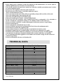
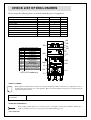
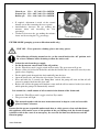
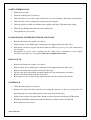
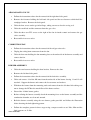
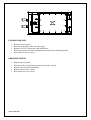
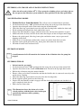
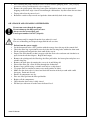
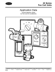
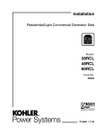
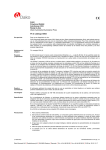
Cooking Systems with Oil
User, Installation and Servicing Instructions
Vortech Gas Fryer
FV7115 and FV7115/F
Lincat Ltd
Whisby Road
Lincoln
LN6 3QZ
Tel +44 (0) 1522 503250
Fax +44 (0) 1522 875530
[email protected]
IS503 ECN 3680
Dear Customer,
Thank you for purchasing this Lincat product.
This is just one of over 450 different items of catering equipment available
which is constantly being extended and improved. Details are available from
your local distributor or direct from us.
Used for the purposes for which it is intended, and with careful maintenance
as outlined in this User Guide, your Lincat product will give you years of
trouble free service.
IMPORTANT INFORMATION
Please read all of the safety and operating instructions carefully before using this
product. Please pay particular attention to all sections of this User Guide that carry
warning symbols and notices.
WARNING!
This is a Warning symbol. This symbol is used throughout the user guide whenever
there is a risk of personal injury. Ensure that these warnings are read and understood
at all times.
CAUTION!
This is a Caution symbol. This symbol is used throughout the user guide whenever there is a
risk of damaging your Lincat product. Ensure that these warnings are read and understood at
all times.
NOTE:
This is a Note symbol. This symbol is used throughout the instructions to provide
additional information, hints and tips.
EQUIPOTENTIALITY
This equipment is provided with an equipotential bonding terminal to allow earth crossbonding with other equipment.
IS503 ECN3680
2
CONTENTS
Contents
Page
Customer Information……………………………………………………….
Warnings and Precautions…………………………………………………
Technical Data………………………………………………………………..
Check List of Enclosures…………………………………………………..
Component Identification……………………………………………………
Installation…………………………………………………….………………
Commissioning………………………………………………………………
Servicing ………………………………………………………………………
Component Replacement ………………………………………….………
Spare Parts List………………………………………………………………
Wiring Diagram........................................................................................
Fault Finding………………………………………………………………….
User Instructions…………………………………………………………….
Service information…………………………………………………………..
Guarantee………………………………………………………….…………..
2
3-4
4
5
5
6
7-8
9
9-12
12
13-14
14-15
16-18
19
19
WARNINGS AND PRECAUTIONS
Please read the following carefully before commencing work on this unit.
WARNINGS AND PRECAUTIONS
This appliance must be installed by a competent installation engineer in accordance with
the installation instructions, and should conform to the following requirements:
•
•
•
•
•
•
•
Gas Safety (Installation & Use ) Regulations
BS 5440: Flues, Air Supply for gas appliances of input not exceeding 70kW (1st, 2nd and 3rd
family gases)
Institution of Gas Engineers publications: IGE/UP/1, IGE/UP/2 and IGE/UP/4
BS 6173: Code of Practice for Installation of Gas Catering Appliances
Local and National Building Regulations
Fire Precautions Act
Health & Safety At Work etc Act
It is mandatory that all appliances are installed, commissioned and serviced by a
qualified and competent person as defined by the regulations in force in the country of
installation. Failure to comply will invalidate the warranty.
This appliance is for professional use only and must only be used by qualified people.
All equipment must be earthed to prevent shock.
Disconnect the unit from the electricity supply before servicing or undertaking any electrical
maintenance.
Parts, which have been protected by the manufacturer or his agent, must not be adjusted by
the installer or user.
IS503 ECN3680
3
If the supply cord is damaged, it must be replaced by the manufacturer, its service agent or
similarly qualified persons in order to avoid a hazard.
Parts of this unit may become hot in normal use; therefore suitable precautions must be taken
to avoid accidental contact.
Do not move this appliance when the tank contains oil.
Hot oil can cause severe burns. Avoid direct physical contact.
Always drain food before frying.
Never put water into the oil, as this will cause splashing and possible overflow of the tank.
Never put anything other than food into the oil.
Never leave the unit unsupervised whilst frying.
If the unit should begin to smoke, switch off immediately.
In the event of a fire occurring, water should not be used to extinguish it. It is advisable to
install a suitable fire extinguisher and have a fire blanket within reach of the fryer.
Do not use old oil, it will have a reduced flash point and be more prone to surge boiling.
Do not overheat the oil.
Do not replenish the oil whilst the fryer is hot.
Do not overfill the tank with oil; maintain the oil level above the minimum mark.
Do not obstruct or block the appliance flue
Do not connect directly to any flue, ducting or mechanical extraction system
Installation should allow for a sufficient flow of fresh air for combustion air supply
Installation must include sufficient ventilation to prevent the occurrence of unacceptable
concentrations of substances harmful to health in the room in which they are installed
It is recommended that this appliance is sited under an extraction canopy for the removal of
combustion products.
Do not use flammable solvents and cleaning aids.
TECHNICAL DATA
Description
Model number
Overall height (mm)
Width (mm)
Depth excluding handles (mm)
Weight (Kg)
Oil capacity (Litres)
Maximum frying weight
Gas inlet connection
Gas pressure – Natural (G20)
Gas pressure – Propane (G31)
Gas pressure – Butane (G30)
Heat input (Gross)
Gas rate – Natural (G20)
Gas rate – Propane (G31)
Gas rate – Butane (G30)
Combustion – Natural (G20)
Combustion – Propane (G31)
Combustion – Butane (G30)
Propane Orifice
Butane Orifice
Power rating (watts)
IS503 ECN3680
Single Tank Gas Fryer
OE7115
OE7115/F
1060
400
830
92
100
16
3.0 kg
3/4” BSP Female
20 mBar
37 - 50 mBar
30 - 50 mBar
22 kW (75,064 Btu’s)
2.10 m3 h-1
1.57 kg h-1
1.60 kg h-1
CO2 – 9.5%±0.2 CO ˂20 PPM
CO2 – 10.5%±0.2 CO ˂20 PPM
CO2 – 11.0%±0.2 CO ˂20 PPM
Ø5.1 mm
Ø4.7 mm
150
750
CHECK LIST OF ENCLOSURES
Please ensure the following items are included with this piece of equipment:
Model
Wire basket
Batter Plate
Drain bucket
Filter Bag/ Filter Bag Frame
Filter Bag Cover
Filter Pad Holder
Filter Pads
User/Installation instructions
Guarantee card
Non Filtration
1
1
1
1
1
0
0
1
1
Filtration
1
1
1
1
1
1
6
1
1
Tick
AA
BB
OO
COMPONENT IDENTIFICATION
AA
KNURLED FASTENER
BB
POWER ON
CC
BURNER ON
DD
THERMOSTAT CONTROL
EE*
PUMP ON
FF*
OPERATING MODE
GG
BURNER RESET
HH
LIMIT STAT RESET
II*
PUMP RESET
JJ
OIL BUCKET
KK
SPLASH GUARD
LL*
FILTER PAD CONNECTION
MM
DRAIN VALVE INDICATOR
NN
DRAIN VALVE HANDLE
OO
WIRE BASKET SUPPORT
* OE7115/F model only.
CC
DD
EE
NN
FF
GG
MM
HH
LL
KK
II
JJ
SERIAL NUMBER
NOTE
Each appliance manufactured at Lincat has a unique identifying number found in the top right hand corner of
the data plate attached at the rear of the appliance. Please record that number in the space provided should it be
required for future reference.
Serial Number
MARK OF CONFIDENCE
Every single product that leaves our factory bears a serial plate showing the assembler’s initials. It’s a
mark of confidence we have in our people and our manufacturing process.
IS503 ECN3680
INSTALLATION
PREPARATION
Remove all packaging materials and protective coatings prior to installation.
VENTILATION
The area in which this equipment is to be installed should have sufficient fixed ventilation to comply
with local legislation requirements. It is recommended that a room or internal space be provided with
a minimum free area of 4.5cm2 per kW (3,400Btu/hr) of total heat input.
SITING
The appliance must be installed in accordance with the appropriate regulations listed prior.
It is recommended that this appliance is sited under an extraction canopy for the removal of
combustion products.
The appliance should be installed on a level surface, in a suitable position that is well lit and draught
free, and positioned to minimise the possibility of accidental touching.
A clear space of at least 100mm must be left to the rear of the appliance to allow for servicing with a
clear space of 600mm to the front to allow for safe operation.
A minimum space of 100mm must be left between any side of the unit and any combustible surfaces
or walls.
Any partitions, walls or kitchen furniture less than 100mm from the appliance must be of noncombustible materials. Should a flexible hose be used the unit must be secured to the wall by
the use of a chain.
ELECTRICAL SUPPLY AND CONNECTION
If the supply cable is damaged it should be replaced by Lincat Ltd or other suitably qualified persons,
in order to avoid a hazard.
For safety regulations the plug or means of disconnection must always be accessible.
This unit must be earthed.
This unit is supplied with a 13 amp plug. If replacing the plug, connect the terminals as follows:
•
•
•
Green and yellow wire
Blue wire
Brown wire
Earth
Neutral
Live
E
N
L
GAS SUPPLY AND CONNECTION
Check that the gas supply corresponds to that specified on the data plate.
Connection is at the rear of the unit via a 3/4" BSP female thread. The gas supply tubing or hose shall
comply with the national requirements in force and shall be periodically examined and replaced as
necessary.
An isolating cock should be fitted into the supply line close to the unit for emergency shutdown or
servicing purposes.
IS503 ECN3680
COMMISSIONING
Never operate the unit without oil in the tank
OPERATIONAL CHECK
Although all Lincat fryers are functionally checked during manufacture, commissioning
must include a functional check of all controls.
PREPARATION
Having sited the unit, with particular attention paid to ventilation and proximity to combustible
materials as detailed previously, the unit is ready for commissioning.
•
•
Connect gas supply and check for gas soundness.
Connect to the electrical supply as previously outlined.
Ensure that the oil drain tap is closed.
Remove the filter pad holder from the oil drain tank
Clean the fryer tank thoroughly with a warm mild detergent solution.
Rinse the tanks, drain pipes and taps, and then dry thoroughly.
Run a small quantity of oil across the bottom of each tank. Open the drain tap and drain any
residual water into the oil drain tank. Coat the base of the tank with a layer of oil.
Close the drain taps.
Empty oil drain tank, dry thoroughly and re-fit oil drain tank back into the base of the fryer.
•
•
•
•
OG7115/F Models only.
Ensure:A carbon filter pad is securely fitted in the filter pad holder
The filter pad holder is placed in the oil drain tank
The filter pad holder flexible hose is securely fitted to the pump suction quick coupling
Fill the tank with oil to the lower level mark.
•
•
•
•
•
•
•
LIGHTING SEQUENCE
•
•
•
•
•
•
Please ensure that the gas isolation valve for the appliance is turned to the open position
before attempting to light this unit.
With the control knob in the off position and the ‘Filter/fryer mode’ toggle switch in fryer
mode, (OE7115/F only) switch the unit on at the isolator. The green neon will light.
Turn the thermostat control knob clockwise to the required temperature.
The adjacent amber neon will light, indicating that the burner is running.
Use a suitable device to check the temperature of the oil at a position 25mm below the surface
of the oil, at the geometric centre of the tank.
Using a calibrated combustion analyser, measure the products of combustion at the appliance
flue outlet.
IS503 ECN3680
Natural gas CO2 – 9.5%±0.1 CO ˂20 PPM
Propane gas CO2 – 10.5%±0.1 CO ˂20 PPM
Butane gas CO2 – 11.0%±0.1 CO ˂20 PPM
•
•
•
If required, adjustment is made via the venturi
throttle screw after removing the access panel.
Anticlockwise increases the gas making the
mixture richer and increasing the CO2
percentage.
Clockwise decreases the gas making the mixture
leaner and decreasing the CO2 percentage.
FILTER MODE (pumping system on filtration model only).
HOT OIL – Wear protective clothing, gloves and safety glasses.
When filtering oil during normal service, set the control knob to the ‘off’ position, wait
for at least 5 minutes before draining to allow the unit to cool.
•
•
•
•
•
•
•
•
Isolate the unit from the gas supply.
Set the thermostat control knob to the off position.
Set the ‘Filter/fryer mode’ toggle switch in filter mode. The green neon will go out.
Ensure a filter pad is fitted in the holder and that the flexible tube is connected correctly to the
quick release coupling.
Fit the splash guard then push the drain tank fully into the fryer.
Open the drain valve and allow the oil to drain. Close the drain valve.
Press and hold (for 5 seconds) the ‘Pump Run’ switch, the pump will start and hot oil will
start to be pumped back into the fryer tank.
Release the switch, the pump will continue to run until the oil has returned to the fryer tank at
which point the pump will automatically turn off.
It is normal for a small amount of oil to remain in the bottom of the drain tank.
•
•
Switch the ‘Filter/Fryer mode’ toggle switch to Fryer mode.
The green neon will light.
This manual together with the user instructions must be kept in a safe and accessible
place for future reference.
Ensure that the person responsible understands how to safely operate, clean and shut down
this appliance and is made aware of the position of the gas isolating cock, the electrical supply
isolation switch in the event of an emergency, the reset for the limit stat, the burner and the
filtration pump.
IS503 ECN3680
SERVICING
We recommend that all servicing, other than routine cleaning, be carried out by our
authorised service agents.
ROUTINE SERVICE
1. Carry out a general check of the installation paying particular attention to the following:• Has the unit been installed using the correct hose?
• Does the unit have a safety chain?
• Does the equipment have a separate isolation valve?
• Is it connected to the supply via a suitable isolating switch?
2. Carry out a gas soundness check.
3. Check that the gas supply is adequate without excessive pressure drop. A test nipple is located on
the gas inlet standpipe.
4. Ensure that the flue is clear and check the combustion with a calibrated instrument.
5. Check the operation of the high temperature limit thermostats. The reset button is located on the
front panel, see diagram.
6. Check the pump operation, the quick release coupling and plug connection and flexible hose
condition and that there is no evidence of leaks on the filtration circuit.
COMPONENT REPLACEMENT
Disconnect from both the gas and electrical supply before proceeding with any of the
following instructions.
Use only genuine Lincat spares.
TEMPERATURE CONTROL
•
Remove the control knob.
•
•
Undo the control panel retaining screws and with the door closed, free the control panel by
prising away from the lower corners of the frame. Use the support bracket located along the
cross member to hold the control panel.
Remove the screws that retain the temperature control/switch assembly to the control panel.
•
Disconnect the cable from the rotary switch.
•
Pull the temperature control from the switch to separate then undo the lock nut.
•
Reassemble in reverse order.
IS503 ECN3680
SAFETY THERMOSTAT.
•
Drain the fryer tank.
•
Undo the control panel (see above).
•
Undo the Allen screw in the centre of the drain valve lever. Remove the handle, and indicator.
•
Undo the four screws retaining the switch panel and support.
•
Undo the gland assembly and withdraw the capillary and bulb. Disconnect the wiring.
•
Undo the nut holding the limit stat to the switch plate.
•
Reassemble in reverse order.
FLAME SENSOR, IGNITER ELECTRODE AND LEADS
•
Remove the drain valve handle (see above).
•
Undo the four screws holding the switch panel and support under the drain valve.
•
Pull off the electrode cap and disconnect from the PCB (if replacing the lead) and unscrew
the electrode.
Reassemble in reverse order ensuring that the earth wire is reconnected on the ignitor
electrode and always use a new gasket. Do not over tighten the screws.
•
DRAIN VALVE
•
Remove the drain valve handle (see above).
•
Undo the four screws holding the switch panel and support under the drain valve.
•
•
•
•
Remove the drain tank and unscrew the oil outlet pipe.
Unscrew the drain valve/elbow assembly taking care not to damage the electrodes.
Remove the elbow fitting from the drain valve.
Reassemble in reverse order using standard practice for the sealing of the threads.
SYSTEM PCB
•
Undo the control panel (see above).
•
Remove the right hand side panel by unscrewing the fasteners at the rear, prising the side
panel from the rear, then sliding forward until clear of the front frame.
•
Identify, then remove all connections. Remove the two fasteners holding the PCB bracket.
•
Withdraw the PCB assembly then undo the M4 nuts to allow removal of the PCB.
•
Reassemble in reverse order.
IS503 ECN3680
AIR/GAS RATIO VALVE
•
Follow the instructions above for the removal of the right hand side panel.
•
Remove the fasteners holding the left hand side panel and the two fasteners which hold the
standpipe bracket. Remove the back panel.
•
Undo the four screws on the gas inlet flange, taking care not to lose the o-ring seal.
•
Undo the earth lead and the connector from the gas valve.
•
Undo the three torx T25 screws to the right of the fan air intake venturi and remove the gas
valve assembly.
•
Reassemble in reverse order.
COMBUSTION FAN
•
Follow the instructions above for the removal of the air/gas ratio valve.
•
Unplug the wiring loom connectors from the fan.
•
Undo the four nuts holding the fan mounting face to the underside of the burner assembly and
remove the fan.
•
Reassemble in reverse order.
BURNER ASSEMBLY
•
Undo the two fasteners holding the door bracket. Remove the door.
•
Remove the left hand side panel.
•
Follow the instructions above for the removal of the fan/valve assembly.
•
Undo and remove 14 of the M8 nuts from the underside of the burner leaving 11 and 12 still
attached. Support the burner and remove the last two nuts and washers.
•
Withdraw the burner from the mounting studs and remove from the left hand side taking care
not to damage the PCB or the metal fibre of the burner surface.
•
Discard the 16 hole burner gasket.
•
Before refitting the burner assembly check the mounting faces on the burner assembly and the
combustion chamber are clean and smooth.
•
Refit the burner assembly using the new burner gasket provided and follow the illustration
below showing the bolt tightening pattern.
•
Follow the complete pattern in three stages using a torque wrench set at 6 Nm, 9Nm and the
final sequence at 12 Nm.
IS503 ECN3680
1
3
5
7
9
12
11
14
13
16
15 2
4
6
8
10
PUMP/MOTOR UNIT
•
•
•
•
•
Remove the rear panel.
Disconnect the pump inlet and outlet pipes.
Remove the live, neutral and earth connections.
Undo the two nuts and lift the pump/motor from the four mounting bushes.
Reassemble in reverse order.
PRESSURE SWITCH
•
•
•
•
•
Remove the rear panel
Disconnect the sensing line pipe from the pressure switch.
Remove the electrical connections.
Remove the pressure switch.
Reassemble in reverse order
IS503 ECN3680
SPARE PARTS LIST
The following components are listed with the Lincat reference number followed by a brief
description.
PART
NUMBER
BA82
BA159
BS08
BU219
GA08
FA112
GA09
VA57
PR67
PR68
TH103
TH104
IG44
IS503 ECN3680
DESCRIPTION
Basket
Half basket
Basket support
Burner
Burner gasket
Combustion Fan
Fan outlet gasket
Air/gas Ratio valve
Main PCB
Interface PCB
Thermistor
Safety thermostat
Ignition lead
IG45
IG43
IG46
TA101/A
LE37
DR06
FB03
FP06
HA77
OP01
OA7937
PS03
SW34
SW72
SW58
HA78
Flame detection lead
Ignitor electrode
Flame detection electrode
Drain valve
Adjustable leg
Drawer runner
Filter bag
Filter pad holder
Door handle
Pump/motor
(30 Pack) Filter pads
Pressure switch
Mode switch
Pump switch/Burner reset
Rotary Switch
Lid handle
PCB
Live
Reset
Power
Neutral Earth
B
B
11
Demand
12
14
Lockout
15 13
16
3
PL201
B
a1
Bb1
B
5
B
c1
B
10
TO PL201
2
B
B
6
4
9
7
B
1
B
see note
EARTH
(PCB)
TO PL201
TO THE GAS VALVE
10
8
Filtration wiring diagram
Note: Use boots on both connections into MA10's.
Do not mix live and neutral inlet and outlet.
PCB
Reset
Live Neutral Earth
B
B
Power
3
6
Demand Lockout
4
7 5
8
11
PL201
B
B
2
10
TO PL201
9
1
see note
EARTH
(PCB)
11
TO THE GAS VALVE
Note: Use boots on both connections into MA10's.
Do not mix live and neutral inlet and outlet.
IS503 ECN3680
10
Non Filtration wiring diagram
PCB wiring diagram
FAULT FINDING
Fryer will not heat up
Check the mains isolator and fuse.
Is the green neon
illuminated on the
front facia?
No
Operate the limit stat reset button.
Check unit is in fryer mode.
(Filtration model only).
Yes
Is the thermostat
turned on?
No
Turn on the
thermostat
Yes
Is the burner reset
red light on
IS503 ECN3680
Yes
Operate the burner reset switch
holding it for at least 5 seconds.
Filtration pump will not work
Is the unit in fryer
mode (green neon
on)?
Yes
Switch the unit
into filter mode.
No
Has the pump
motor thermal
trip activated.
Yes
Reset thermal trip
See below.
No
Check the pump for
correct operation.
No
Disconnect the Filter
pad holder quick
release coupling.
Can you feel suction at
the female connection?
Yes
Check the braided hose
and fittings for a
blockage and replace
the filter pad.
Has this resolved
the problem?
No
Pump/motor thermal trip
reset button
IS503 ECN3680
Consult a qualified
engineer.
USER INSTRUCTION
Model No.
OG7115-OG7115/F
Capacity
16 litres
Max. load
3.0 kg
When filtering oil during normal service, set the control knob to the ‘off’ position, wait
for at least 5 minutes before draining to allow the unit to cool.
Do not operate this unit without oil in the tank.
Before operating fill with cold oil to the lower oil level.
During operation maintain the oil level to the upper indicated level.
Never operate the pump without a carbon filter pad fitted into the pad holder.
Do not run water through the filtration system.
Isolate from the gas supply before draining oil from the fryer tank.
FILL WITH OIL
To prevent accidental opening of the drain valve, the handle must be pushed onto the drain
valve before turning. The valve can then be opened by turning the depressed handle anticlockwise.
•
•
Check that the drain valve is in the closed position.
When cold fill the tank of the fryer to the lower level marked on the batter plate.
SOLID FATS
•
•
•
When using solid fat, remove the batter plate, cut the fat into small pieces and place
approximately 8 kg into the base of the fryer tank.
Replace the batter plate and press firmly onto the fat. Place another 6 kg of fat on top of the
batter plate along the side walls of the fryer tank.
Select the ‘M’ (melt cycle) on the control knob and when all the fat has melted and the lower
level has been reached, set the required temperature.
FRYER OPERATION
•
•
•
•
Turn on the power supply at the isolating switch, the green neon will light. For the filtration
model, select fryer mode on the ‘Filter/fryer mode’ toggle switch, the green neon will light
indicating the unit is in fryer mode and that mains power is on.
Turn the thermostat control knob to the required temperature setting.
The amber neon will light indicating that the burner light sequence has begun.
When the oil reaches the selected temperature the amber neon will go out.
BASKET LOADS
Overloading the basket reduces the fryer output of cooked product and will result in uneven
cooking. It also increases the possibility of surge boiling (the oil may suddenly boil over when
the basket is placed into the tank).
Food that is over-wet increases the possibility of surge boiling.
IS503 ECN3680
FILTERING, OIL CHANGE AND CLEANING INSTRUCTIONS
Allow the oil to cool to below 40O C. Wear protective clothing, gloves and safety glasses.
Do not operate the filtration system without a filter pad fitted to the filter pad holder.
NON FILTRATION MODEL
•
•
•
•
•
•
•
•
•
•
•
Isolate the fryer from the mains. This will prevent accidental burner operation.
Set the thermostat to the “Off” position with the orange dot at the top of the control dial.
Open the door then pull out the drain tank using the attached handle.
Check the filter bag is positioned correctly in the four locating holes within the drain tank.
Fit the splashguard and push the drain tank all the way in.
Depress the drain handle to engage with the drain valve and turn anti-clockwise to open.
Drain half of the oil; fully close the drain value then dispose of the oil. Repeat until empty.
Remove the splash guard, filter bag, batter plate and baskets onto a tray to prevent oil
dripping on the floor
Wipe clean or clean through a dishwasher, remove any debris from the fryer tank.
Dry then return splash guard, filter bag, batter plate and baskets for next time.
Fill with oil to the lower indicated level.
FILTRATION MODEL
A small amount of oil will remain in the bottom of the oil bucket after the pump has
stopped.
FILTERING THE OIL
•
•
•
•
•
•
•
•
•
Isolate from the gas supply.
Set the thermostat to the “Off” position with the orange dot at the top of the control dial.
Open the door then set the switch to Filtration mode located in the top right-hand corner.
Pull out the oil bucket using the attached handle.
Ensure a filter pad is fitted in the holder and that the flexible tube is connected correctly to the
quick release coupling.
Check the filter bag is positioned correctly in the four locating holes.
Fit the supplied splash guard over the filter bag.
Depress the drain handle so that it engages with the drain valve and turn anti-clockwise to
open, completely drain the oil.
Fully close the drain value.
The illustration shows the drain valve in the
closed position, with the drain valve in the open
position the indicator will be pointing
downwards.
IS503 ECN3680
•
•
•
•
Press and hold the pump switch for a few seconds until the pumping starts. (The pumping
operation will stop automatically when complete).
Remove the splash guard, filter bag, batter plate and baskets onto a tray to prevent oil
dripping on the floor, wipe clean or clean through a dishwasher, dry then return for next time.
Top up with oil to the correct level.
Return the switch to Fryer mode and push the drain tank fully back in for storage
OIL CHANGE AND CLEANING OF THE FRYER
Do not run water through the pump.
Do not submerge the filter pads in water.
Always use the correct filter pad.
Lincat part number OA7937 (30 pack)
The oil must only be emptied from the fryer when it is cool.
For ease of handling and disposal empty half the oil at a time.
•
•
•
•
•
•
•
•
•
•
•
•
•
•
•
•
Isolate from the power supply.
Set the thermostat to the “Off” position with the orange dot at the top of the control dial.
Check the filter bag is positioned correctly in the four locating holes within the drain tank.
Fit the splashguard and push the drain tank all the way in.
Depress the drain handle so that it engages with the drain valve and turn anti-clockwise to
open, drain the oil then dispose. Repeat until empty.
Remove the splashguard, the filter bag, the filter pad holder, the batter plate and place on a
suitable drip tray.
Remove the back plate by turning the screws A-A and lifting off.
Discard the filter pad, clean all items through the dishwasher.
Remove large partials using a suitable tool such as a chip shovel.
Use paper towel or similar to remove any small partials of debris.
Make sure the drain valve is closed and wash the interior of the fryer tank with a mild
detergent. Drain and discard.
Ensure all components are dry.
Fit a new filter pad into the filter pad holder.
Replace all the components.
Check that the drain valve is fully closed.
Fill the fryer with new oil to the lower indicated level.
IS503 ECN3680
SERVICE INFORMATION
Gas catering equipment should be routinely serviced to ensure a long trouble free life.
It is recommended that this appliance is serviced every 6 months by a competent gas engineer.
For help regarding the installation, maintenance and use of your FriFri equipment, please call:
LINCAT SERVICE HELP DESK
01522 875520
AUTHORISED SERVICE AGENTS
We recommend that all servicing other than routine cleaning is carried out by our authorised service
agents we cannot accept responsibility for work carried out by other persons.
Please quote both the model and serial numbers from the data plate attached to the unit. Give brief
details of the service requirement.
If possible please quote the product code of the part number you require.
Work carried out under warranty will normally be undertaken only during normal working hours, i.e.
Monday to Friday, 8.30 a.m. - 5.00 p.m.
CONDITIONS OF GUARANTEE
The guarantee does not cover:1)
2)
3)
Accidental breakage or damage
Operational misuse, wear and tear from normal usage, incorrect adjustment, or neglect.
Incorrect installation, maintenance, modification or unauthorised service work.
IS503 ECN3680