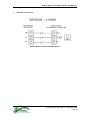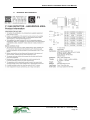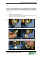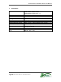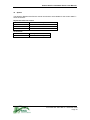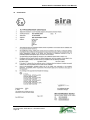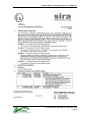
1
Analox 9000 F1 Flammable Sensor User Manual Analox Sensor Technology Ltd. 15 Ellerbeck Court, Stokesley Business Park North Yorkshire, TS9 5PT, UK T: +44 (0)1642 711400 W: www.analox.net F: +44 (0)1642 713900 E: [email protected] Analox 9000 F1 Flammable Sensor User Manual List of Contents 1 2 3 4 5 6 7 8 9 10 11 12 13 14 15 Introduction ........................................................................................................................6 Principle of Operation ........................................................................................................7 L.E.L. and U.E.L.................................................................................................................9 Sensor Signal Cables ......................................................................................................10 Instrument Calibration......................................................................................................11 Sensor Physical Details ...................................................................................................12 Electrical Connections .....................................................................................................13 Sensor Installation ...........................................................................................................14 Hazardous Area Installation.............................................................................................15 Replacing the Sensor Insert.............................................................................................16 Specifications ...................................................................................................................18 Spares..............................................................................................................................19 Certification ......................................................................................................................20 Disposal ...........................................................................................................................30 Appendix ..........................................................................................................................31 Document Ref: GDS-860-01 - December 2010 Page 4 Analox 9000 F1 Flammable Sensor User Manual Document Ref: GDS-860-01 - December 2010 Page 5 Analox 9000 F1 Flammable Sensor User Manual 1 Introduction The ANALOX 9000 F1 Range of sensors are designed to detect Flammable gas, mainly methane (CH4) in ambient air monitoring applications. The model is listed below: Model 9000 F1 which is of the Explosion proof type The Model 9000 F1 consists of a 316 stainless steel sensor unit certified EExd IIC T6 II2GD, mounted in a glass reinforced polyester fire retardant junction box, which is certified EExe T6 II2GD. The Model 9000 F1 unit junction box includes 1 x 20mm threaded cable gland entry. A Certified blanking plug is supplied with the unit. The Pellistor inserts used in the 9000 sensors are of the poison resistant variety. The sensor can be supplied with either CAT300, CAT170 and CAT335 type Pellistor inserts; Operating currents are 300 mA (2.0 volts), 170 mA (2.0 volts) and 335mA (2.5 volts) respectively. The CAT300 have a larger active element and is slightly more resistant to poisoning than the CAT 170 but if the area to be monitored is unlikely to contain poisoning substances then other considerations may determine which Pellistors are chosen. Document Ref: GDS-860-01 - December 2010 Page 6 Analox 9000 F1 Flammable Sensor User Manual 2 Principle of Operation 2.1 The elements used in these sensors are of the Catalytic Pellistor type and are sensitive to most common combustible gases and vapours. 2.2 A single sensor assembly may therefore be used to detect a wide range of these gases. The devices are made from two coils of very fine platinum wire which are embedded in separate beads of alumina. One device is the detector and the other is a temperature compensating element. The detecting element is treated with a catalyst which promotes oxidation of the gas and the compensating element is treated with an oxidation inhibiting agent. 2.3 The two elements are connected to the Instrument in a Half Bridge configuration and the excitation current passing through them raises their temperature to about 550 Deg C. At this temperature, the gas oxidises on the detector element and raises the temperature of the bead even further. This alters the resistance of the detector bead and this change in resistance is measured by the monitor instrument and converted to produce a reading of the gas concentration on the Instrument display. 2.4 The output of the device is essentially linear for most gases up to high concentrations, typically 100% LEL and the response time to 25% LEL is about 2 or 3 seconds. Any pre-filtering of the gas before it reaches the sensor may lengthen the response time. If the sensors are required to operate in high gas concentrations for short periods, it has been found that for periods up to about 2 minutes, 10 second bursts of 8%, 10% and 80% methane in air, produce no ill effects. Prolonged exposure can result in zero drift which may be reversed by operating for a short period in clean air. Exposure to 40% concentration for longer periods will begin to destroy the detector surface, altering the Zero point and reducing the sensitivity. Whenever a sensor is exposed to high concentrations of combustible gas, the calibration should be rechecked as soon as possible. 2.5 The performance of the sensors may be temporarily impaired by operation in the presence of certain volatile substances containing halogens or sulphur. The sensors may recover after a short period of operation in clean air. Whenever the substance produces a permanent effect on the catalyst, resulting in a large reduction in sensitivity, the sensor is said to be Poisoned. Typical substances which can cause poisoning are silicon oils and grease, anti-knock petrol additives and phosphate esters. Activated carbon filters will provide adequate protection from poisoning in most cases. Notwithstanding the above comments, the combustible gas sensors have an inherently long life. Although the sensors respond to most combustible gases, the signals produced vary in magnitude depending on the actual gas to which the sensor is exposed. The sensors should normally be calibrated using 50% LEL methane, i.e. 2.5% methane in air. NOTE: When the sensors are used to detect a different gas than that used for calibration, then a correction factor should be applied to the readings obtained. A table showing conversion factors for various gases is shown in Appendix A of this manual. (See also ‘Instrument Calibration’ section) WARNING: When a pellistor type sensor is exposed to concentrations of flammable gas greater than 100% LEL (5% methane in air) there eventually comes a point at Document Ref: GDS-860-01 - December 2010 Page 7 Analox 9000 F1 Flammable Sensor User Manual which the signal output from the sensor DECREASES as a result of an INCREASING concentration of the gas. This is caused by the flammable gas displacing oxygen in the sample and gradually inhibiting the normal oxidation process at the detecting element. Most monitoring instruments provide an OVER-RANGE indication to inform the user of this condition. (See also ‘L.E.L. and U.E.L.’ section) Document Ref: GDS-860-01 - December 2010 Page 8 Analox 9000 F1 Flammable Sensor User Manual 3 3.1 L.E.L. and U.E.L. The above principle of operation is only valid where the gas mixture to be sensed contains oxygen. It is therefore suitable for detection of leakages of gases in atmospheric surroundings, where it is important to know the level of concentration, well before a hazardous situation arises. Flammable gas mixtures are only ignitable between certain fairly clear, but experimentally defined limits. These levels are known as the 'Lower Explosive Limit' (L.E.L.) and the 'Upper Explosive Limit' (U.E.L.). Typical L.E.L. figures for some common explosive gases are as follows: Methane (Natural Gas) 5% + 95% Air Hydrogen 4% + 96% Air Ammonia 16% + 84% Air Ethylene 3% + 97% Air Butane 1.9%+ 98.1% Air Propane 2.1%+ 97.9% Air 3.2 If the gas concentration is below the L.E.L. then combustion cannot take place due to insufficient gas, and if above U.E.L. level, there will be insufficient Oxygen present to sustain combustion. Document Ref: GDS-860-01 - December 2010 Page 9 Analox 9000 F1 Flammable Sensor User Manual 4 Sensor Signal Cables 4.1 All the Analox flammable gas sensors require a three core cable between the sensor and the measuring instrument. Because of the relatively heavy current demands of the pellistor type of sensors the connecting cables must be chosen with care. For example, Pellistors of the CAT300 type require an operating potential (at the Sensor) of 2.00 volts DC at a current of 300 milliamps. When a current of this magnitude is passed along signal cables, any significant resistance in the cables will result in a drop in voltage along the cables. As an example: Assume a cable run of 100 metres is required between the monitoring instrument and the sensor and the cross sectional area of the cable chosen is 1.00mm2. Most manufacturers quote the resistance of this cable to be 19.1 Ohms per kilometre; therefore in this case, a 100 metre length will have a resistance of 19.1 / 10 = 1.91 Ohms. Bearing in mind that as far as the loop current is concerned, the actual conductor length is 200 metres; (100m to the sensor and 100m back again) the total cable resistance in this case is 3.82 Ohms. Using Ohm's law to calculate the voltage drop across the entire cable: Voltage Drop = Current x Resistance Where Voltage is in Volts: Current is in Amps & Resistance is in Ohms Voltage Drop = 0.3 x 3.82 = 1.15 Volts 4.2 This means that if the monitoring instrument supplies a drive voltage of 2.00 volts then the sensor will only have 0.85 Volts applied to it. (2.00v-1.15v=0.85v). The pellistor sensor will NOT operate correctly in this condition. 4.3 NOTE: Although the ANALOX 9000 F1 sensors use a 3 wire connecting cable, only two of the wires carry the sensor excitation current. The third wire is connected to the centre tap of the 'Half Bridge' configuration. It only carries a signal voltage at very low current and may therefore be ignored as far as resistance effects are concerned. Most monitoring instruments designed to operate with flammable gas detectors of the pellistor type have the facility for compensating, within limits, for this voltage drop. The ANALOX range of monitors (GDS-404) allow the drive voltage to be adjusted up to about 3.8 volts. So, in the case of the above installation, the 1.15 volt drop across the cable could be compensated by adjusting the monitoring instrument drive voltage to 3.15 volts. It is not necessary to carry out all of these calculations every time an installation is done - correct operation of the sensor can be achieved by measuring the voltage AT THE SENSOR JUNCTION BOX TERMINALS. A further point, which is often overlooked, is that the resistance of copper cable has a temperature co-efficient. The effect of this variation in resistance due to temperature changes can be significant on very long cable runs, particularly if the cable has a small cross sectional area and is subject to large variations in temperature. The measuring instrument is unable to distinguish between a change in cable resistance and a genuine gas signal. Copper cable resistance is normally quoted at 20°C and will vary by approximately 0.4% per degree C, as the temperature changes above and below this value. Using the above cable installation as an example, the total loop resistance was calculated to be 3.82 Ohms at 20°C. If the temperature of the cable drops to 0°C then the resistance will change to 3.80 Ohms. At first sight, this may not seem significant but could result in drift of the ZERO reading on the monitoring instrument. Document Ref: GDS-860-01 - December 2010 Page 10 Analox 9000 F1 Flammable Sensor User Manual 5 Instrument Calibration 5.1 There is some confusion over what is meant by the sensitivity of instruments used to measure the concentrations of combustible gas. Ideally, all units employing catalytic combustion as the measuring principle should be calibrated in terms of percentage of potential combustibility, where 100% scale reading represents an ignitable mixture, for a particular Gas/Air mixture. 5.2 It is unfortunate that the sensing elements are not equally responsive to all combustible gas/air mixtures and although the sensitivity to a wide range of gases is similar to within a few percent of L.E.L., and for all practical purposes, the inaccuracies may be ignored, it may be desirable in certain cases to make allowances for these variations. 5.3 It is therefore common practice to calibrate units of this type over the range 0 - 100% L.E.L. where 100% scale is equal to the actual percent concentration of the calibration gas, at the Lower Explosive Limit. For example, an instrument calibrated 0-100% L.E.L. methane would indicate 100% scale at 5.0% gas concentration and one calibrated for Butane would indicate 100% scale at 1.9% gas concentration. Document Ref: GDS-860-01 - December 2010 Page 11 Analox 9000 F1 Flammable Sensor User Manual 6 Sensor Physical Details Analox 9000 F1 Series Flammable Gas Sensor Document Ref: GDS-860-01 - December 2010 Page 12 Analox 9000 F1 Flammable Sensor User Manual 7 Electrical Connections Analox 9000 F1 Series Flammable Sensor Document Ref: GDS-860-01 - December 2010 Page 13 Analox 9000 F1 Flammable Sensor User Manual 8 Sensor Installation 8.1 Care should be exercised during installation not to damage the sintered element on the front surface of the device. IT IS PARTICULARLY IMPORTANT THAT THEY ARE NOT EXPOSED TO SILICON BASED SUBSTANCES OR HALOGENS, either during installation or in their normal operating condition. This could lead to the sensors being poisoned, as described above in section 2 of this manual. 8.2 The type of gas to be detected determines, in general, the physical location of the sensor. Whereas a gas that is heavier than air will require a low sensor mounting position, a lighter than air gas will necessitate an elevated mounting point. 8.3 Consideration should be given to those areas where it is anticipated that leakage may occur. For example, in the vicinity of valves, pipe flanges, compressors, etc, and also to the possibility of pockets of gas collecting in the event of a leak. In this respect, heavier than air gases, for example propane or butane, may tend to accumulate in floor ducts, pits etc. and ventilation should be provided for these areas as a normal precaution. Lighter than air gases e.g. methane or hydrogen will tend to accumulate between ceiling joists, in roof spaces etc and similar consideration should be given to adequate ventilation. 8.4 Additionally, the effects of any ventilation must be considered in the siting of gas sensors and it may be prudent to mount sensors in air extraction ducts. However, excessive velocities can affect the sensors and it may be necessary to provide a degree of draught protection. TABLE 1 below shows examples of molecular weights of some common flammable gases and groups them in categories according to their weight, relative to air. Lighter than Air Hydrogen 2.0 Ammonia 17.0 Ethylene 28.0 Methane 16.0 Carbon Monoxide 28.0 Acetylene 26.0 Heavier than Air Ethane 30.1 Butane 58.1 Pentane 72.2 Hexane 86.2 Hydrogen Sulphide Propane Toluene Heptane TABLE 1. Relative Molecular weight of common gases NOTE: AIR = 29 The flammable sensors should be mounted with the sinter facing downward, whether it is mounted high or low. Document Ref: GDS-860-01 - December 2010 Page 14 34.0 44.1 92.1 100.2 Analox 9000 F1 Flammable Sensor User Manual 9 Hazardous Area Installation Document Ref: GDS-860-01 - December 2010 Page 15 Analox 9000 F1 Flammable Sensor User Manual 10 Replacing the Sensor Insert The expected operating life of most sensors varies. However, if the sensor is constantly exposed to high doses of its specific gas, or gases to which it is cross sensitive then its life span will be reduced in proportion to the concentration/exposure time. It is a matter for the user to decide whether the sensor is replaced automatically at a pre-determined interval, or if it is left until a time when it is no longer possible to calibrate. This will depend on the nature of the application. 10.1 Sensor Insert Replacement Procedure 1) Isolate the sensor from its power supply and wait 3 minutes before proceeding to allow any power stored in the sensor to dissipate. 2) Remove the sensor head grub screw using a 1.5mm Allen key. Grub Screw 3) Unscrew the sensor head cap. 4) Remove the white sensor mount from the sensor insert and then remove the sensor insert by gently pulling it from the housing. Document Ref: GDS-860-01 - December 2010 Page 16 Analox 9000 F1 Flammable Sensor User Manual 5) Fit the new sensor insert into the housing. Note the orientation of the sensor connector pins and housing connector sockets, the cell can only be fitted in the correct orientation. Sensor Pins Housing Sockets 6) Refit the white sensor mount. 7) Refit the sensor head cap. 8) Refit the sensor head grub screw. 9) Re-apply power to the sensor. Allow approximately one hour for the new sensor to settle and then carry out the calibration procedure. 10.2 Disposal of Discarded Sensor When the life of the sensor has expired or otherwise damaged it must be disposed of safely in accordance with local regulations. According to WEEE regulation this electronic product can not be placed in household waste bins. Please check local regulations for information on the disposal of electronic products in your area. Document Ref: GDS-860-01 - December 2010 Page 17 Analox 9000 F1 Flammable Sensor User Manual 11 Specifications Classification ATEX SCS Cert No. IECEx SCS Cert No. UK Design patent Housing Material Dimensions Weight Cable Exit Mounting Thread Accessory Mounting Thread Lock Screw Housing Components Ingress Protection Approved sensor boxes junction Certified flameproof ATEX / IECEx – Exd IIC T6 Gb CSA/US Class 1 Groups A, B, C, D. High temperature versions 03ATEX1176X IECEx SIRO6.0016X No. 2025396 Stainless Steel 316 S16 Body length 32mm dia 33mm 165gms 20mm 1.5 pitch – options available 25mm, 3/4 NPT 33mm 1.25 pitch 3mm-1mm key Body ref. 001-002 End cap ref. 001-003 IP63 + water shield IP65 Type 9000 – EExe II T6 Material – GRP - IP66 Document Ref: GDS-860-01 - December 2010 Page 18 Analox 9000 F1 Flammable Sensor User Manual 12 Spares The following Replacement Sensor Inserts /Accessories are available for the Analox 9000 F1 series of sensors: Replacement Sensor Inserts Part Number Description 9100-1300 F1 CAT 300A Sensor Insert – 300mA 9100-1170 F1 CAT 170A Sensor Insert – 170mA 9100-1410 F1 CAT 335A Sensor Insert – 335mA Accessories Part Number 6000-0048 Description F1 Sensor Flow Adaptor Document Ref: GDS-860-01 - December 2010 Page 19 Analox 9000 F1 Flammable Sensor User Manual 13 Certification Document Ref: GDS-860-01 - December 2010 Page 20 Analox 9000 F1 Flammable Sensor User Manual Document Ref: GDS-860-01 - December 2010 Page 21 Analox 9000 F1 Flammable Sensor User Manual Document Ref: GDS-860-01 - December 2010 Page 22 Analox 9000 F1 Flammable Sensor User Manual Document Ref: GDS-860-01 - December 2010 Page 23 Analox 9000 F1 Flammable Sensor User Manual Document Ref: GDS-860-01 - December 2010 Page 24 Analox 9000 F1 Flammable Sensor User Manual Document Ref: GDS-860-01 - December 2010 Page 25 Analox 9000 F1 Flammable Sensor User Manual Document Ref: GDS-860-01 - December 2010 Page 26 Analox 9000 F1 Flammable Sensor User Manual Document Ref: GDS-860-01 - December 2010 Page 27 Analox 9000 F1 Flammable Sensor User Manual Document Ref: GDS-860-01 - December 2010 Page 28 Analox 9000 F1 Flammable Sensor User Manual Document Ref: GDS-860-01 - December 2010 Page 29 Analox 9000 F1 Flammable Sensor User Manual 14 Disposal According to WEEE regulation this electronic product can not be placed in household waste bins. Please check local regulations for information on the disposal of electronic products in your area. Document Ref: GDS-860-01 - December 2010 Page 30 Analox 9000 F1 Flammable Sensor User Manual 15 Appendix A feature of the pellistor combustible gas detectors is the almost universal response to LEL of hydrocarbons. Almost all detectable gases produce a similar output at LEL. This table lists the theoretical factors by which the signal with a Calibration gas should be multiplied to give the equivalent signal for other gases. Gas/Vapour Acetic Acid Acetone Ammonia Butyl Acetate Cyclo-hexane Cyclo-pentane Decane Dioxane Ethane Ethanol Ethyl Acetate Ethylene Hydrogen Iso-Butane Iso-butyl Alcohol Iso-Octane Iso-Pentane Iso-Propyl Alcahol (IPA) Methane Methanol Methyl Ethyl Ketone (MEK) n-Butane n-Heptane n-Hexane Nonane n-Pentane n-propanol n-Propyl Alcahol Propane Propylene Styrene Monomer Toluene Benzene Iso-Butyl Methyl Ketone LEL (CENELEC Standards) 5.40% 2.60% 15% 1.40% 1.30% 1.40% 0.75% 2.00% 3.00% 3.30% 2.20% 2.70% 4.00% 1.80% 1.70% 0.95% 1.40% 2.20% 5% 6.70% Relative Response (with respect to Methane) 0.2 0.35 0.65 0.3 0.45 0.5 0.2 0.5 0.85 0.45 0.35 0.65 0.95 0.55 0.3 0.35 0.45 0.35 1 0.7 1.90% 1.80% 1.05% 1.02% 0.85% 1.40% 2.20% 2.20% 2.10% 2.40% 1.1 1.20% 1.30% 1.20% 0.35 0.55 0.4 0.45 0.25 0.5 0.4 0.4 0.6 0.7 0.3 0.4 0.35 0.25 Gain Adjustment 5 2.86 1.54 3.33 2.22 2 5 2 1.18 2.22 2.86 1.54 1.05 1.82 3.33 2.86 2.22 2.86 1 1.43 2.86 1.82 2.5 2.22 4 2 2.5 2.5 1.67 1.43 3.33 2.5 2.86 4 Document Ref: GDS-860-01 - December 2010 Page 31