1
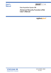
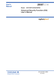
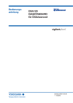
User’s
Manual
Daqstation DX1000/DX1000N/
DX2000 and DAQSTANDARD
Functional Changes Resulting
from the Updating
(Applies to DX1000/DX1000N/DX2000 with hardware
style 2 or later and firmware release 2 or later as well as
DAQSTANDARD version 7.21 or later)
*
4
L
4
1 B 1
0
3 E 0
1
IM 04L41B01-03E
1st Edition
*
Contents
Overview of the Functional Changes..........................................................................................................................4
Checking the Style Number and Release Number on the Name Plate......................................................................4
Operations on the DX1000/DX1000N/DX2000..............................................................................................................5
Improvement to the Operability on the Historical Trend Display.................................................................................5
Displaying the Data in the Grid Time of the Trend Display.........................................................................................5
Improvement to the Display Group Setup Operation..................................................................................................6
Specifying the Base Position of the Bar Graph...........................................................................................................6
Alarm Output Relay Action When the Alarm ACK Operation Is Executed..................................................................9
Resetting the Computed Value during Computation (/M1 and /PM1 Options).........................................................10
Changes to How the Data Files Are Named.............................................................................................................10
Sorting the Files by the Update Date/Time...............................................................................................................11
Storage Method for Constantly Retaining the Most Recent Data Files in the CF Card (Media FIFO)......................12
Progress Display When Saving All Data of the Internal Memory..............................................................................14
Changing the Initial Display Selection Menu............................................................................................................14
Improvement to the Data Save Operation to the USB Flash Memory......................................................................14
Retaining the State of the CapsLock and NumLock Keys on the USB Keyboard....................................................14
Function for Automatically Assigning MW100s to the Modbus Client (DX2000 Only)..............................................15
Changing of the Default Setting of the Web Server Function...................................................................................18
A List of Added Messages........................................................................................................................................18
Communication Commands........................................................................................................................................19
Specifying the Base Position of the Bar Graph.........................................................................................................19
Storage Method for Constantly Retaining the Most Recent Data Files in the CF Card (Media FIFO)......................19
Format of the File List Output Using the ME Command...........................................................................................19
Alarm Output Relay Action When the Alarm ACK Operation Is Executed................................................................20
DAQSTANDARD for DXAdvanced...............................................................................................................................21
Hardware Configurator.............................................................................................................................................21
Viewer.......................................................................................................................................................................23
IM 04L41B01-03E
Thank you for purchasing the Daqstation DX1000/DX1000N/DX2000 (DX). This manual
covers functions that has been changed in hardware style 2 and firmware release 2 or
later. It also covers functions that have been changed on DAQSTANDARD version 7.21
or later. Change the contents of the following manuals with the contents of this manual.
Manuals Provided on the CD-ROM
Manual Title
Daqstation DX1000/DX1000N
User’s Manual
Daqstation DX2000
User’s Manual
Daqstation
DX1000/DX1000N/DX2000
Communication Interface
User’s Manual
DXA120
DAQSTANDARD for
DXAdvanced User’s Manual
Manual No.
IM 04L41B01-01E
IM 04L42B01-01E
IM 04L41B01-17E
Description
See this manual for the descriptions of the
DX1000/DX1000N operations.
See this manual for the descriptions of the
DX2000 operations.
See this manual for the descriptions of
communication commands.
IM 04L41B01-61E
See this manual for the descriptions of the
DAQSTANDARD operations.
Manual No.
IM 04L41B01-02E
Description
Explains the basic operations of the
DX1000/DX1000N.
Explains the basic operations of the
DX2000.
Paper Manuals
Manual Title
Daqstation DX1000/DX1000N
Operation Guide
Daqstation DX2000
Operation Guide
IM 04L42B01-02E
1st Edition : February 2007 (YK)
All Right Reserved, Copyright © 2007, Yokogawa Electric Corporation
IM 04L41B01-03E
Overview of the Functional Changes
Below is an overview of the main functional changes.
• Improvement to the Operability on the Historical Trend Display
When changing to the all data display, the DX loads as much of the continuous data
as the display memory can hold and shows the data.
• Alarm Output Relay Action When the Alarm ACK Operation Is Executed
You can select the mode in which the alarm output relay is turned OFF when alarm
ACK is executed and remains OFF until the next alarm occurs.
• Addition of the Media FIFO Function
If not enough free space is available when saving a new data file to the CF card, files
are deleted in order from the oldest data update date/time to save the new file.
• Function That Automatically Assigns MW100s to Modbus Clients
When connecting MW100s to the DX using the Modbus/TCP communications, the
MW100 channels can be assigned automatically to the DX external input channels.
* Only on DX2000s with the external input channels (/MC1 option).
• NEMA4 Compliance (Only the Waterproof Construction)
The waterproof construction of the DX front panel complies with the NEMA4 standard.
Checking the Style Number and Release Number on the Name Plate
As shown below, the style number and release number are marked on the name plate
attached to the DX.
MODEL
STYLE
H
S
2
SUFFIX
SUPPLY
2
Firmware release number
Hardware style number
FREQUENCY
NO.
IM 04L41B01-03E
Operations on the DX1000/DX1000N/DX2000
Below are the operational changes as a result of the functional changes. This section
mainly uses the DX1000 display in the explanations.
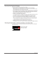
Improvement to the Operability on the Historical Trend Display
Loading Operation of Continuous Data to the Display Memory
All Data Display
When all data display is enabled, as much of the past measured data that are continuous
to the measured data shown on the screen at that point as the display memory can hold
are loaded. This allows you to view the past measured data without having to load the
data for each screen.
• Conventional Display Method
Shows only the display data that was
showing before the change when
switching to the all data display.
• New Display Method
Loads as much of the continuous data
as the display memory can hold and
shows the data when switching to the
all data display.
Section 4.3, “Displaying Past Measured Data (Historical Trend Display)” in the user’s
manual
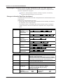
Displaying the Data in the Grid Time of the Trend Display
If the trend update interval is set to 1h/div or higher, the month, day, and hour at the grid
position are displayed on the screen. The display format can be changed by setting the
date format.
Date Format
Display Format of the Grid Time
Display Example
Year/Month/Day
Month/Day/Year
Day/Month/Year
Day.Month.Year
MM/DD hh
MM/DD hh
DD/MM hh
DD.MM hh
12/31 08
12/31 08
31/12 08
31.12 08
Section 2.4, “Setting the Date Format” in the user’s manual
IM 04L41B01-03E
Operations on the DX1000/DX1000N/DX2000
Improvement to the Display Group Setup Operation
The channel settings of a display group can be copied to another group.
Setup Screen
Press MENU (switch to the setting mode) and select Group set, Trip line
Procedure
1. Select the copy source channel settings.
2. Press the Copy soft key.
3. Select the copy destination channel settings.
4. Press the Paste soft key. The channel settings are copied.
Section 5.1, “Setting Display Groups” in the user’s manual
Specifying the Base Position of the Bar Graph
The base position of the bar graph can be set to span lower limit (scale lower limit) or
span upper limit (scale upper limit). The setting is applied when displaying the bar graph
and when displaying the current value on the scale using the bar graph.
Setup Screen
Press MENU (switch to the setting mode) and select Meas channel > Bar Graph
IM 04L41B01-03E
Operations on the DX1000/DX1000N/DX2000
Setup Items
• Bar graph > Base position
Set the base position of the bar graphs to Normal, Center, Lower, or Upper. The bar
graphs for the different settings are shown below.
When the Display Direction of the Bar Graph Is Vertical
• Normal
Value at the bottom of the bar graph:Span lower limit or span upper limit (or scale
lower limit or scale upper limit), whichever is
less
Value at the top of the bar graph:Span lower limit or span upper limit (or scale
lower limit or scale upper limit), whichever is
greater
Starting point of the bar:
Bottom edge
• Center
Value at the bottom of the bar graph: Same as with Normal.
Value at the top of the bar graph:
Same as with Normal.
Starting point of the bar:
Center
• Lower
Value at the bottom of the bar graph: Span lower limit (or scale lower limit)
Value at the top of the bar graph:
Span upper limit (or scale upper limit)
Starting point of the bar:
Bottom edge
• Upper
Value at the bottom of the bar graph: Same as with Lower.
Value at the top of the bar graph:
Same as with Lower.
Starting point of the bar:
Top edge
Normal
Center
Lower
Upper
VL
VL
Vupper
Vupper
VS
VS
Vlower
Vlower
Vupper:
Vlower:
VL:
VS:
:
Span upper limit (or scale upper limit)
Span lower limit (or scale lower limit)
Vlower or Vupper, whichever is greater
Vlower or Vupper, whichever is less
Starting point of the bar
Example: When the span lower and upper limits of the input
range are 0.0 and –100.0, respectively
Normal
Center
Lower
Upper
IM 04L41B01-03E
0.0
0.0
–100.0
–100.0
-100.0
-100.0
0.0
0.0
Operations on the DX1000/DX1000N/DX2000
When the Display Direction of the Bar Graph Is Horizontal
The span lower limit (or scale lower limit) becomes the left edge of the bar graph, and
the span upper limit (or scale upper limit) becomes the right edge of the bar graph.
• Starting point of the bar
Normal: Left edge or right edge, whichever is less
Center: Center
Lower: Left edge
Upper: Right edge
Normal
Vlower
(Vlower < Vupper)
Vupper
Lower
Vlower
Vupper
Vupper
Upper
Vlower
Vupper
(Vlower > Vupper)
Center
Vlower
Vupper: Span upper limit (or scale upper limit)
Vlower: Span lower limit (or scale lower limit)
:
Starting point of the bar
Example: When the span lower and upper limits of the input
range are 0.0 and –100.0, respectively
0.0
–100.0
Normal
Center
Lower
Upper
0.0
–100.0
0.0
–100.0
0.0
–100.0
When Displaying the Current Value on the Scale Using the Bar Graph
Normal
Center
Lower
Vlower
Upper
Vupper
Normal
(Vlower < Vupper)
Vupper
(Vlower > Vupper)
Center
Lower
Vlower
Upper
Section 5.11, “Changing the Bar Graph Display Method” in the user’s manual
Operation using communication commands: Page 19
IM 04L41B01-03E
Operations on the DX1000/DX1000N/DX2000
Alarm Output Relay Action When the Alarm ACK Operation Is Executed
You can select the relay output status that is enabled after the alarm ACK operation from
the following two settings.
• Normal:The relay output is deactivated when the alarm ACK operation is executed.
If the condition for activating the alarm output relay is met in the next scan
interval, the relay output is activated.
This operation is valid only when the alarm output relay is set to Hold.
• Reset:The relay output is deactivated when the alarm ACK operation is executed.
If a new condition for activating the alarm output relay is met, the relay is
activated.
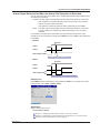
An example of the relay action when alarm ACK is executed is shown below. This
example is for the case when the output relay AND item is set to OR and the Hold item is
set to Hold.
• Normal
Alarm ACK
Alarm 1
Alarm 2
Alarm output relay
ON
OFF
Relay is activated in the next scan interval
• Reset
Alarm ACK
Alarm 1
Alarm 2
Alarm output relay
ON
OFF
Relay is activated on the next alarm occurrence
Setup Screen
Press MENU (switch to the setting mode), hold down FUNC for 3 s (switch to the basic
setting mode), select Alarm > Switch, Relay
Setup Items
Relay > Relay Action on Ack
Select Normal or Reset.
Section 3.5, “Setting the Auxiliary Alarm Function” in the user’s manual
Section 3.8, “Releasing the Alarm Output (Alarm ACK Operation)” in the user’s manual
Operation using communication commands: Page 20
IM 04L41B01-03E
Operations on the DX1000/DX1000N/DX2000
Resetting the Computed Value during Computation (/M1 and /PM1 Options)
You can reset the computed value not only when the computation is stopped but also
when the computation is in progress.
Section 9.4, “Starting/Stopping Computation, Resetting Computation, and Releasing
Computation Data Dropout Display” in the user’s manual
Changes to How the Data Files Are Named
The table below shows the file name that is assigned when the measured data is saved
to the CF card.
Differences from the File Names up to Now
• The “ID” item at the end of the file name is deleted and its functionality is included in
the “Separator” of the 7-digit sequence.
• The sequence section of the display data and event data file names is changed to
7 digits, and the “ID” function is included in the “Separator” when using the “Batch
name.”
Structure
Date
Description
Display data
Event data
Manual sampled data
Snapshot data
Report data
7-digit
. Extension
Date
Specified string
Ex.: 000123_AAAAAAAAAAA050928_174633.DAD
7-digit
Type . Extension
Date
Specified string
Ex.: 000123_AAAAAAAAAAA050928_174633HD.DAR
Sequence
Display data
Event data
Manual sampled data
Snapshot data
Report data
7-digit
. Extension
Specified string
Ex.: 000123_AAAAAAAAAAA.DAD
7-digit
Specified string
Type . Extension
Ex.: 000123_AAAAAAAAAAA0HD.DAR
Batch name
Display data
Event data
Report data
7-digit
Batch name
. Extension
Ex.: 000123_BBBBBBBBBBBBBBBBBBBBB.DAD
7-digit
Date
Type . Extension
Ex.: 000123_050928_174633HD.DAR
Manual sampled data
Snapshot data
10
7-digit
Date
. Extension
Ex.: 000123_050928_174633.DAM
Item
7-digit sequence 000001~999999
Description
Consists of a 6-digit number and a separator. The number is
assigned in order of occurrence.
When the 6-digit number reaches 999999, it returns to 000000.
The separator starts with an underscore followed by a character
that changes in the following order: A to Z and then 0 to 9.
Date
YY: Year (lower two digits), MM: Month, DD: Day
HH: Hour, Mi: Minute, SS: Second
YYMMDD_HHMiSS
Specified string AAAAAAAAA•••A
Up to 16 alphanumeric characters can be used
Batch name
BBBBBBBBBBB•••B
Up to 40 alphanumeric characters can be used
Type
H_, D_, W_, M_,
HD, DW, DM
Report data type
H_: Hourly, D_: Daily, W_: Weekly, M_: Monthly,
HD: Hourly and daily, DW: Daily and weekly,
DM: Daily and monthly
Extension
Display data
Event data
Manual sampled data
:DAD
:DAE
:DAM
Report data
Snapshot data
Setup data
:DAR
:PNG
:PDL
IM 04L41B01-03E
Operations on the DX1000/DX1000N/DX2000
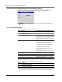
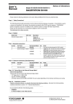
Sorting the Files by the Update Date/Time
The files can be sorted in order by the update date/time in the screens below. This
function allows you to easily locate the files you need.
• File list/delete
• Load display data
• Load event data
• Load settings (setting mode)
• Load settings (basic setting mode)
Procedure
The procedure is explained using the “File list/delete” screen of the CF card as an
example.
1. Press MENU (switch to the setting mode) and select Save/Load > File list/delete
> CF soft key* > DISP/ENTER
* When a CF card and a USB flash memory (/USB1 option) are being used
2. Press the Sort soft key to sort the files by the update date/time.
Pressing the Sort key sorts the file list in order from
the oldest to newest update date/time, or vice versa.
Each time the key is pressed thereafter, the sort
order reverses. The arrow next to the Date/Time
column title indicates ascending or descending order.
: Sorts from oldest update date/time (ascending)
: Sorts from newest update date/time
(descending)
IM 04L41B01-03E
11
Operations on the DX1000/DX1000N/DX2000
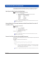
Storage Method for Constantly Retaining the Most Recent Data Files in the CF
Card (Media FIFO)
When saving the data files automatically, you can save the data so that the most recent
data files are constantly retained in the CF card. This method allow you to use the DX
continuously without having to replace the CF card.
Operation
Old
Deleted
File 1
Update date
File 2
New
File 3
Saved
File 4
Medium
If not enough free space is available when saving a new data file to the CF card, files are
deleted in order from the oldest data update date/time to save the new file. This operation
is referred to as FIFO (First In First Out).
• The FIFO operation is carried out only when saving the following files automatically.
It is not carried out when saving files to the save destination directory using another
method.
Display data files, event data files, report data files, manual sample data files, and snapshot
files
• Files that are deleted
All the files in the save destination directory are applicable to be deleted. However, the
following files are excluded.
Hidden files, read-only files, files in the subdirectory within the save destination directory
• The most recent 1000 files are retained. If the number of files in the save destination
directory exceeds 1000, the number of files is held at 1000 by deleting old files even
if there is enough free space. If there are more than 1000 files already in the save
destination directory, one or more files are always deleted before saving the new file.
Setup Screen
Press MENU (switch to the setting mode), hold down the FUNC key for 3 s (switch
to the basic setting mode), and select Environment > Security, Media save
Setup Items
Save > Auto save
Select On.
Save > Media FIFO
Select On.
Section 6.2, “Setting the Method for Saving the Data” in the user’s manual
Operation using communication commands: Page 19
12
IM 04L41B01-03E
Operations on the DX1000/DX1000N/DX2000
Status Display of the CF Card
• If an error occurs on the CF card, the CF card icon in the status display section
changes to an error display.
An error occurred while accessing the CF card.
(White)
Detected an error when the CF card was inserted or performed
a key operation to eject the CF card when an error was occurring
(Light blue) while the CF card was being accessed.
• If the media FIFO is turned ON, the icon does not turn red even when the free space
on the CF card falls below 10% of the total CF card size.
Section 1.3, “Display” in the user’s manual
E-mail Transmission of CF Card Errors
• An e-mail message can be sent when an error occurs on the CF card.
• If the media FIFO is turned ON, an e-mail message is not sent even when the free
space on the CF card falls below 10% of the total CF card size.
To send e-mail message of CF card errors, set the DX to send a system mail.
Setup Screen
Press MENU (switch to the setting mode), hold down the FUNC key for 3 s (switch
to the basic setting mode), and select Communication (Ethernet) > E-mail
Section 1.4, “Sending E-mail Messages” in the communication interface user’s manual
Relay Contact Output When a CF Card Error Occurs (/F1 and /F2 Options)
A relay contact output can be activated when an error occurs on the CF card.
Setup Screen
MENU key (switch to the setting mode) > Hold down the FUNC key for 3 s (switch
to the basic setting mode), and select Status Relay
Setup Items
Memory/Media status
Select On.
Section 2.9, “Outputting the DX Status via the Relay Contact” in the user’s manual
Operation When a CF Card Error Occurs
Carry out the procedure below to reset the CF card icon to normal and release the relay
output.
• Replace the CF card with a normal one.
• Format the CF card on the DX.
IM 04L41B01-03E
13
Operations on the DX1000/DX1000N/DX2000
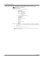
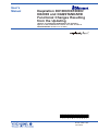
Progress Display When Saving All Data of the Internal Memory
If you carry out All Save* on the memory summary screen, a pop-up window appears
showing the progress of the save operation.
* Function for saving all data in the internal memory to a CF card or USB flash memory.
Note
• The pop-up window appears only when the memory summary display is showing.
• If you press the ESC key, the pop-up window clears temporarily and reappears
approximately 10 seconds later.
• The time estimate for saving all data is indicated in the table below (when the memory is full
of data). It may take longer depending on the operating conditions of the DX.
Time to Save All Data (Estimate)
Save Destination
CF Card
USB Flash Memory
Standard memory (internal memory size suffix code -1) 4 minutes 16 minutes
Expansion memory (internal memory size suffix code -2) 10 minutes 40 minutes
Section 4.8, “Using the Memory Summary” in the user’s manual
Changing the Initial Display Selection Menu
SELECT SAVE and ALL SAVE are shown in the initial display menu.
Section 4.8, “Using the Memory Summary” in the user’s manual
Section 5.17, “Changing the FUNC Key Menu and Display Selection Menu” in the user’s
manual (section 5.18 for the DX2000)
Improvement to the Data Save Operation to the USB Flash Memory
Save data is displayed only when a flash memory is connected to the USB port and is
usable* in the operation mode.
* If DX is configured so that any of the items below is shown in the display menu, Save data
can be executed. You can change the items shown in the display menu using the menu
customize function.
SELECT SAVE, M.SAMPLE SAVE, REPORT SAVE, or ALL SAVE
Section 2.12, “Using the USB Flash Memory (/USB1 Option)” in the user’s manual
Section 5.17, “Changing the FUNC Key Menu and Display Selection Menu” in the user’s
manual (section 5.18 for the DX2000)
Retaining the State of the CapsLock and NumLock Keys on the USB Keyboard
The state of the CapsLock and NumLock keys is retained even if you disconnect the
USB keyboard.
Section 2.11, “Controlling the DX with a Keyboard (/USB1 Option)” in the user’s manual
14
IM 04L41B01-03E
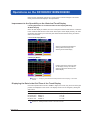
Operations on the DX1000/DX1000N/DX2000
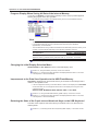
Function for Automatically Assigning MW100s to the Modbus Client (DX2000
Only)
If the DX2000 is a Modbus client, MW100s, Modbus servers on the network, can be
automatically assigned to the DX2000. This function can be used only on DX2000s with
the external input channel function (/MC1 option).
Setup Preparation
Set the MW100s so that measurements can be started (IP address, system construction,
range setting, and the like of the MW100s to be automatically assigned). For details, see
the user’s manual of the MW100.
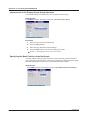
Setup Procedure
If the IP address of the DX is not set, set it before carrying out the procedure below.
1. Press MENU (switch to the setting mode), hold down the FUNC key for 3 s (switch
to the basic setting mode), and select Communication (Ethernet) > Modbus
client > Auto setting
2. Carefully read the displayed precautions.
Select Yes to execute the auto setting. Select No to return to the screen
operation.
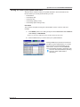
3. From the list of MW100s that is displayed, select the MW100s to be connected
using the up and down arrow keys, and press DISP/ENTER. The selected
MW100s are assigned to the external input channel of the DX.
Displays the IP address or host name.
Displays the MW100 unit number. The list displays up
to 16 units from the smallest unit number.
Displays the status of the external input channel assignments.
No settings:
Status in which the MW100 is not
assigned automatically
Not Ready:
Status in which the MW100 cannot be
connected*
Numeric display: Displays the number of the assigned
external input channels
Example: If a MW100 is assigned to
external input channels 201
to 220, the status displays
201/220.
* For the corrective action, see "A List of
Added Messages" on page 18.
Pressing the Call soft key causes “--” to blink on the 7-segment LED display of the selected MW100 for 2 seconds.
This allows you to check which MW100 is selected if multiple MW100s are connected.
IM 04L41B01-03E
15
Operations on the DX1000/DX1000N/DX2000
Setup Items
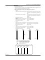
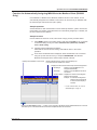
The MW100 channels are assigned to the external input channels of the DX as follows:
• Channel Number
The channels of the MW100 selected first are assigned consecutively from external
input channel 201. The channels of the MW100 selected next are assigned to the
available external input channels from the smallest number. You cannot select the
external input channels to be assigned.
DX external
input channels
DX
MW100 meas.
channels
CH201
CH001
CH220
CH020
CH221
CH001
CH240
CH014
CH241
CH001
CH270
CH030
Order of automatic
assignment
MW100
MW100
MW100
MW100
Meas. channels
CH001 to CH020
1
Meas. channels
CH001 to CH004,
CH011 to CH014
2
Meas. channels
CH001 to CH030
3
• Range Settings
The range settings of the MW100 (including the span and unit) are set automatically
to the external input channels.
If the span setting of the MW100 range exceeds the span setting range of the DX
external input channel (–30000 to 30000), it is set to the span upper limit (30000) or
lower limit (–30000).
Specify the settings such as the alarm, tag, and the area display of the color scale band
of each channel after the auto setting is complete.
Note
Precautions When Assigning Channels to the External Input Channels
• The MW100 channels are assigned in unit of 10 channels to the external input channels. If
the MW100 measurement module consists of less than 10 channels, “OFF” is assigned to
the external input channels for the section without channels.
• An error occurs if the number of MW100 channels to be automatically set is greater than the
number of available external input channels.
• If the range setting of a MW100 channel is set to “SKIP,” the external input channel of the
DX is set to “OFF.”
• If a MW100 unit contains a module that cannot be set automatically, only the channels that
can be assigned are assigned to the external input channels of the DX.
• If a new MW100 is added, auto setting is executed again. At this point, all the settings are
cleared. Therefore, you must execute the auto setting again for all MW100s.
• If you are connecting MW100s that can be automatically set and MW100s that cannot
be automatically set or other Modbus devices, automatically set the MW100s that can be
automatically set first and then manually set the connection of the remaining devices.
16
IM 04L41B01-03E
Operations on the DX1000/DX1000N/DX2000
Note
About the MW100
• MW100s that support auto setting are those with firmware version R2.22 or later.
• MW100 modules that can be automatically set are the following input modules.
4-CH, High-Speed Universal Input Module
10-CH, Medium-Speed Universal Input Module
6-CH, Medium-Speed Four-Wire RTD Resistance Input Module
10-CH, High-speed Input Module
• If there are no channels to be assigned or the Modbus server setting is OFF, auto setting
fails with an error. Check the settings.
• MW100s that are connected through auto setting automatically switches to the measurement
mode.
• Port number 34324 of the MW100 is used to perform auto setting.
• For details on the MW100 settings, see the user’s manual of the MW100.
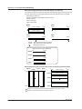
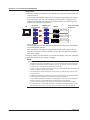
The first channel information of the MW100 that is automatically set to the external input
channel can be displayed when the cursor is on the first or last channel.
In addition, the status of the connected MW100 can be confirmed on the Modbus status
display screen.
IM 04L41B01-03E
17
Operations on the DX1000/DX1000N/DX2000
Changing of the Default Setting of the Web Server Function
The default setting of the Web server function has been changed to Use. You can use
the Web server function by setting the monitor page or operator page to On.
Section 1.5, “Monitoring the DX on a PC Browser” in the communication interface user’s
manual
A List of Added Messages
The following error messages have been added.
Code
129
131
132
Message
IP address is not set.
You have exceeded the available
channel capacity.
You have exceeded the available
number of commands.
133
External I/O auto setting information
is not available.
134
135
136
Auto setting has already been
executed.
External I/O cannot be found.
External I/O start cannot be executed.
137
DNS for this device is not set.
Explanation/Countermeasures/Ref. section
Set the IP address of the DX.
You cannot connect more than 240 channels.
The maximum number of commands that can
be sent is 16. The modules that can be set with
a single command are consecutive modules that
can be automatically set. Change the MW100
module configuration so that there are no empty
slots.
Below are the possible causes. Check them.
•T
he MW100 is in calibration mode. Change to
the setting mode or measurement mode.
• The measurement module may not have been
detected. Perform system reconfiguration.
• There are no modules that can be
automatically set. Check the modules.
• An IP address has not been assigned to the
MW100. Set the IP address.
• The Modbus server of the MW100 is turned
OFF. Turn ON the server.
You cannot set an MW100 that has been
automatically set.
Check the Ethernet connection.
The current MW100 settings do not allow the
measurement to be started. Check the settings.
Set the DNS of the DX.
In addition, the following status messages have been added. These messages appear
when the respective processing operation takes a long time.
Code
513
514
515
516
Message
Post process in progress.
Now loading historical data.
Data save is completed.
Files are now being sorted.
Section 10.1, “A List of Messages” in the user’s manual (section 11.1 for the DX2000)
18
IM 04L41B01-03E
Communication Commands
Communication commands are described in chapter 3, “Commands” in the DX1000/
DX1000N/DX2000 Communication Interface User’s Manual (IM 04L41B01-17E).
Specifying the Base Position of the Bar Graph
SB Sets the bar graph for each channel
Syntax SB p1,p2,p3<terminator>
p1 Measurement/computation/external input channel number
p2 Base position of the bar graph display
NORMAL
Normal (lower limit)
CENTER
Center
LOWER
Lower limit
UPPER
Upper limit
p3 Number of scale divisions (4 to 12)
Section 3.4, “Setting Commands (Setting)” in the communication interface user’s manual
Settings on the DX: Page 6
Storage Method for Constantly Retaining the Most Recent Data Files in the CF
Card (Media FIFO)
WU Sets the environment
Set the media
Syntax
Example
WU p1,p2,p3<terminator>
p1 Setting type (MEDIA)
p2 Auto save function (OFF or ON)
p3 Media FIFO (OFF or ON)
Use media FIFO.
WUMEDIA,ON,ON
Section 3.6, “Basic Setting Commands” in the communication interface user’s manual
Settings on the DX: Page 12
Format of the File List Output Using the ME Command
Because the method of assigning the file name has been changed, the output format has
also changed.
The number of output file name characters is 51.
● Syntax
EACRLF
yy/mo/dd_hh:mm:ss_ssssssss_fff•••_0_xxx•••CRLF
••••••••••••••••••••••••••••••••••••••••••••••
ENCRLF
fff••• name (51 characters including the extension. If it is less than 48, spaces
are entered. If this is a directory, the characters <DIR> are shown at the
position displaying the file data size.
Section 4.2, “Output Format of ASCII Data” in the communication interface user’s manual
IM 04L41B01-03E
19
Communication Commands
Alarm Output Relay Action When the Alarm ACK Operation Is Executed
WO Set alarm and DO settings
Set the Output Relay
Syntax WO p1,p2,p3,p4,p5<terminator>
p1 DO type (RLY)
p2 Relay number
NONENo AND setting
I01Specify only I01
I01-IxxSpecify I01 to Ixx
xx={02 to 36}
p3 Energize/De-energize the relay
DE_ENERGIZE
ENERGIZE
p4 Hold/Not hold the relay
NONHOLD
HOLD
p5 Relay action on ACK
NORMAL
RESET
ExampleNo AND operation of the output relay, relay action is energize, and release
the relay output when the alarm ACK operation is performed regardless of the
alarm status.
WORLY,NONE,ENERGIZE,HOLD,RESET
Section 3.6, “Basic Setting Commands” in the communication interface user’s manual
Settings on the DX: Page 9
20
IM 04L41B01-03E
DAQSTANDARD for DXAdvanced
The functions below have been added or changed since DAQSTANDARD revision 7.21.
Hardware Configurator
Setup Menu Corresponding to the DX Functions of Firmware Version 2.0x
• Specifying the Base Position of the Bar Graph
Applies to the operations on the [Measure channel], [Math channel], or [Ext channel]
tab screen.
Bar Display Position
Set the base position of the bar graphs to [Normal], [Center], [Lower], or [Upper].
Operations on the DX1000/DX1000N/DX2000: Page 6
• Alarm Output Relay Action When the Alarm ACK Operation Is Executed
Select [Alarm] on the [Basic Setting] tab screen.
Relay Action on ACK
NormalThe relay output is deactivated when the alarm ACK operation is executed.
If the condition for activating the alarm output relay is met in the next scan
interval, the relay output is activated.
This operation is valid only when the alarm output relay is set to [Hold].
ResetThe relay output is deactivated when the alarm ACK operation is executed. If
a new condition for activating the alarm output relay, the relay is activated.
Operations on the DX1000/DX1000N/DX2000: Page 9
• Storage Method for Constantly Retaining the Most Recent Data Files in
the CF Card (Media FIFO)
Select [Environment] > [Detail Setting] on the [Basic Setting] tab screen.
Media FIFO
This is valid only when [Auto Save] is [ON].
ONIf there is no more free space on the CF card, the oldest file is deleted, and the
newest file is saved.
OFFIf there is no more free space on the CF card, the measured data is not saved to
the CF card.
Operations on the DX1000/DX1000N/DX2000: Page 12
IM 04L41B01-03E
21
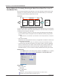
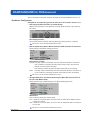
DAQSTANDARD for DXAdvanced
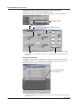
Dialog Box for Setting the Display Type for Each View Group
Select [View group] on the [General Setting] tab screen.
Double-click the view group number to display a dialog box for setting each group.
View group number
Enter the view group name
Select the type of views to be displayed or drag
and drop the view icons
Select the group to be displayed
Selectable view types
Section 3.5, “Entering General Settings” in the DAQSTANDARD for DXAdvanced User’s
Manual
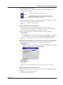
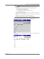
Setting the Expression
This applies to the operation for setting the expression on the setup screen of each
computation channel. You can display a list of variables and constants and click the
desired variables or constants to create the expression.
Click the tab to display
a list of that item
Section 3.4, “Setting the Computation Channels” in the DAQSTANDARD for DXAdvanced
User’s Manual
22
IM 04L41B01-03E
DAQSTANDARD for DXAdvanced
Viewer
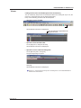
Linking the Previous and Subsequent Files Collectively
You can collectively link previous and subsequent files to the working file. Up to now, the
previous or subsequent file could be linked sepaparately.
Carry out the following procedure with the file opened.
• Operation on the Toolbar
Click here
All linkable files are linked and displayed.
The .ldx extension is appended to the
original file name.
• Operation from the Menu Bar
On the [File] menu, click [Link All Files].
All linkable files are linked and displayed.
• Operation on the Link File Dialog Box
On the [Window] menu, click [Link].
The [Link File] dialog box opens.
Click [All].
All linkable files are linked and displayed.
Section 4.5, “Linking Files and Saving the Link Settings File” in the DAQSTANDARD for
DXAdvanced User’s Manual
IM 04L41B01-03E
23