1
ROCKALL
USER’S MANUAL
USER’S MANUAL
Information in this document is subject to change without notice. No part of this manual may be
reproduced or transmitted in any form or by any means, electronic or mechanical including
photocopying, recording, or information storage and retrieval systems, without the prior written
permission of the manufacturer.
FT S.r.l. - All rights reserved.
Airserco Manufacturing Company LLC
7555 Tyler Blvd
Unit 7
Mentor, Ohio 44060
USA
Tel. 1-440-946-2700
Fax 1-440-946-8188
Email: [email protected]
Web: www.airserco.com
Microsoft, Windows and DOS are recorded marks of Microsoft Corporation.
Release 2.0 January 2009
Airserco won't be held responsible for potential inaccuracies that may be printed inside
this manual, in the sketches, in the figures or in any other enclosed document distributed by Airserco
Manufacturing.
2
USER’S MANUAL
INDEX
INDEX ....................................................................................................................................................................3
INTRODUCTION .................................................................................................................................................7
CONVENTIONS .................................................................................................................................................8
SOFTWARE INSTALLATION ..........................................................................................................................8
SOFTWARE EXECUTION ................................................................................................................................8
RELEASE NOTES ..............................................................................................................................................9
SAFETY DIRECTIVES ......................................................................................................................................11
INTRODUCTION .............................................................................................................................................11
1.1 ELECTRICAL SAFETY .............................................................................................................................12
1.2 HYDRAULIC SAFETY ..............................................................................................................................13
1.3 MECHANICAL SAFETY ...........................................................................................................................14
1.4 SAFETY OF THE WORKING AREA.........................................................................................................16
1.5 REFRIGERANT FLUIDS SAFETY INSTRUCTIONS ..............................................................................16
1.6 FIRE AND/OR EXPLOSION RISKS OF REFRIGERANT FLUIDS..........................................................17
1.7 RISKS RELATED TO TOXIC REFRIGERANT FLUIDS..........................................................................17
1.8 RISKS RELATED TO THE EMPLOYMENT OF REFRIGERANT FLUIDS SUPPLY TANKS ..............17
1.9 INSTALLATION.........................................................................................................................................19
1.9.1 INSTALLATION PROCEDURE FOR ROCKALL WITH VORTFILLER+ ...........................................19
1.9.2 INSTALLATION PROCEDURE FOR ROCKALL WITH ISSO.............................................................20
TECHNICAL DESCRIPTION...........................................................................................................................21
INTRODUCTION .............................................................................................................................................21
2.1 ROCKALL SUB-SYSTEMS .......................................................................................................................21
2.1.1 FILLER .................................................................................................................................................21
2.1.2 INJECTION SYSTEM ...........................................................................................................................22
2.1.3 CONTROL SYSTEM .............................................................................................................................23
2.1.4 VACUUM SYSTEM...............................................................................................................................23
2.1.5 REFRIGERANT METERING SYSTEM ................................................................................................23
2.1.6 NITROGEN AND/OR HELIUM INJECTION LINE .............................................................................23
2.2 GENERALITY ON ROCKALL MACHINE ...............................................................................................24
2.2.1 CABINET ..............................................................................................................................................24
2.2.1.1 ELECTRONIC CONTROL UNIT.................................................................................................................. 26
2.2.1.2 ELECTRICAL UNIT...................................................................................................................................... 28
2.2.1.3 PRINTER (optional) ....................................................................................................................................... 28
2.2.1.4 REFRIGERANT METERING SYSTEM ....................................................................................................... 30
2.2.1.5 INJECTION SYSTEMS ................................................................................................................................. 32
2.2.1.6 ONLY VACUUM FILLER (optional)............................................................................................................ 32
2.2.1.7 VACUUM AND CHARGING FILLER ......................................................................................................... 33
2.2.1.8 VACUUM SYSTEM ...................................................................................................................................... 38
2.2.1.9 PNEUMATIC SYSTEM (IF PRESENT) ....................................................................................................... 39
FUNCTIONAL DESCRIPTION ........................................................................................................................42
3
USER’S MANUAL
INTRODUCTION .............................................................................................................................................42
3.1 EVACUATION AND CHARGING CYCLE WITH A FILCAS FILLER ...................................................42
3.1.1 SELECTION OF THE WORKING CYCLE...........................................................................................45
3.1.2 CONNECTION OF THE FILLER TO THE COOLER CIRCUIT .........................................................45
3.1.3 FILLER EVACUATION (CONFIGURABLE AND OPTIONAL) ..........................................................45
3.1.4 CHARGED GROUP TEST (CONFIGURABLE AND OPTIONAL)......................................................45
3.1.5 COOLER CIRCUIT EVACUATION .....................................................................................................46
3.1.6 LEAK TEST...........................................................................................................................................46
3.1.7 REFRIGERANT FLUID CHARGING ..................................................................................................46
3.1.8 DISCONNECTION OF THE FILLER FROM THE COOLER CIRCUIT .............................................47
3.2 EVACUATION AND REFRIGERANT CHARGING CYCLE WITH ISSO FILLER ................................47
3.3 EVACUATION AND REFRIGERANT CHARGING CYCLE WITH VORTFILLER+ ............................50
3.4 FUNCTIONAL DESCRIPTION OF A MIXTURE AND OVERPRESSURE TEST CYCLE WITH
TRACER GAS...................................................................................................................................................53
CONTROL PANEL.............................................................................................................................................56
INTRODUCTION .............................................................................................................................................56
4.1 DISPLAY.....................................................................................................................................................56
4.2 KEYBOARD ...............................................................................................................................................57
MONITORING WINDOW.................................................................................................................................58
INTRODUCTION .............................................................................................................................................58
5.1 MOVE A WORKING CYCLE TO THE MONITOR AND START IT .......................................................59
5.2 REMOVE THE WORKING CYCLE FROM THE MONITOR ..................................................................61
5.3 WORKING CYCLE MONITORING ..........................................................................................................61
5.4 ENTER THE WINDOW MENU .................................................................................................................62
CYCLES MENU ..................................................................................................................................................64
INTRODUCTION .............................................................................................................................................64
6.1 PARAMETERS OF A WORKING CYCLE ................................................................................................64
6.2 OVERPRESSURE TEST CYCLE PARAMETERS ....................................................................................66
6.3 VIEW CYCLE WINDOW ...........................................................................................................................67
6.4 INSERT CYCLE WINDOW .......................................................................................................................68
6.5 MODIFY CYCLE WINDOW......................................................................................................................69
6.6 LINK CYCLES ............................................................................................................................................70
MACHINE MENU ..............................................................................................................................................72
INTRODUCTION .............................................................................................................................................72
7.1 SET MACHINE ...........................................................................................................................................72
7.2 SET FLOWMETERS...................................................................................................................................74
7.3 SET INJECTORS (FILLERS) .....................................................................................................................75
7.4 SET INJECTION SYSTEMS ......................................................................................................................76
7.5 SET MEASURE UNITS (NEXT RELEASE) ...................................................................................................78
7.6 SET PRESSURE RANGE ...........................................................................................................................80
7.7 SENSORS CALIBRATION ........................................................................................................................81
SERVICE MENU ................................................................................................................................................82
INTRODUCTION .............................................................................................................................................82
8.1 REFRIGERANT SUPPLY WINDOW ........................................................................................................82
4
USER’S MANUAL
8.2 SYSTEM OPTIONS ....................................................................................................................................83
8.3 PRIVATE VALUES ....................................................................................................................................84
8.4 CHANGE PASSWORD...............................................................................................................................85
8.5 RESTART....................................................................................................................................................85
8.6 TEST OUTPUT ...........................................................................................................................................85
OPERATING ROCKALL STEPS .....................................................................................................................86
INTRODUCTION .............................................................................................................................................86
9.1 EVACUATION AND CHARGING CYCLE...............................................................................................87
9.2 EVACUATION AND/OR OVER-PRESSURE TEST CYCLE ...................................................................89
9.3 LIGHT SIGNALLERS (OPTIONAL) .........................................................................................................90
9.4 ACOUSTIC SIGNALLER (OPTIONAL)....................................................................................................90
9.5 CYCLE BLOCK ..........................................................................................................................................90
9.6 ALERTS ......................................................................................................................................................91
5
USER’S MANUAL
6
USER’S MANUAL
INTRODUCTION
This manual describes the procedures for a correct and safe use of ROCKALL. It provides also a
simple and complete guide for user’s interface: through this interface it is possible to configure,
select, enter and check the working cycles during their execution.
The introduced notions don't force to a sequential reading, but you must read the Chapter 1
about SAFETY DIRECTIVES, before you operate the machine.
The CHAPTER 1 illustrates the SAFETY DIRECTIVES.
The CHAPTER 2 illustrates the ROCKALL TECHNICAL DESCRIPTION.
The CHAPTER 3 illustrates the ROCKALL FUNCTIONAL DESCRIPTION.
The CHAPTER 4 describes the CONTROL PANEL.
The CHAPTER 5 explains how you can select, remove and start a WORKING CYCLE.
The CHAPTER 6 explains how you can open, create, modify and delete a WORKING CYCLE.
The CHAPTER 7 explains the MACHINE CONFIGURATION.
The CHAPTER 8 describes the available SERVICES.
The CHAPTER 9 describes the machine working and the possible operator’s actions during the
working cycle of ROCKALL.
Refer to the ROCKALL MAINTENANCE MANUAL for the maintenance instructions and for fault
finding.
7
USER’S MANUAL
CONVENTIONS
The following conventions are used in this manual:
Symbols
Description
TAB
Capital letters point out keyboard keys, and technical
words
ITALIC
Words in italic point out technical terms or products
names
[[ optional]]
The values between double parenthesis are optional
value 1, value 2...
3 dots point out the presence of more values
ENTER
It is the key "carriage return"
"text"
The double apexes point out a constant value of string
type
LEFT, RIGHT, UP, DOWN
They point out the left, right, up and down arrow keys
ESC
It points out the "escape" key
SOFTWARE INSTALLATION
The machine software is installed by FT, therefore you don’t need to perform any additional
operation.
SOFTWARE EXECUTION
The machine software starts automatically when you switch the machine on.
8
USER’S MANUAL
RELEASE NOTES
This manual refers to the machine software release 1.9 (Mrc01.09).
Mrc01.09 allows you to perform the following operations:
•
•
•
•
•
•
•
•
•
Machine configuration
Refrigerant pressure threshold setting
Measure units selection
Temperature, pressure and vacuum sensors calibration
Flow meter sensors calibration
Refrigerant supply management
Inserting, deleting, modifying and displaying of working cycles
Selection/removal of working cycles
Injection systems monitoring through:
1. Displaying of temperature and pressure values on each charging line.
2. Displaying of working operations for each injection system.
3. Displaying of instantaneous percentage of refrigerant charge while ROCKALL in charging a
cooler circuit.
4. Displaying of alert messages.
• printer and barcode reader management
• cooler circuit overpressure test management
9
USER’S MANUAL
10
USER’S MANUAL
1
SAFETY DIRECTIVES
INTRODUCTION
ROCKALL performs the evacuation, the leak test and the refrigerant fluid injection on cooler circuits.
It has been designed and manufactured for a simple and safe use. But the use of compressed air,
refrigerant fluids, mechanical seals under pressure and electrical power supply needs trained personnel
to work in safety.
The knowledge and the comprehension of the content of this manual are a necessary condition so that
trained personnel can perform maintenance and use operations in safety.
Important safety information is given as warning and caution instructions; you have to pay attention to
these instructions. The use of warnings and cautions is defined below.
WARNING
Observe these precautions, avoiding injuries to users.
CAUTION
Observe these precautions, avoiding damages to ROCKALL.
For a complete description of the electrical, mechanical and pneumatic devices refer to the Chapter 2
of the enclosed User’s Manual.
11
USER’S MANUAL
1.1 ELECTRICAL SAFETY
The wires and the devices of ROCKALL are inside the cabinet with safety degree equal or better than
IP2X (EN 60529 Directives). Therefore the operators of ROCKALL are protected from direct and
indirect contacts, voluntary or no voluntary, with the active parts of the electrical circuits.
When the main switch on the frontal panel of the machine (A in figure 1.1) is on the "0" position, the
power supply is present only on the main switch, on the side equipped with a proper protection against
voluntary or involuntary contacts (figure 1.2).
A
Figure 1.1 Frontal panel of the electrical unit
In order to remove the power supply from the machine, you must put a general multi-pole
switch upstream from the machine. This switch must have a differential protection and the
ground cable must be never sectioned.
12
USER’S MANUAL
PWR
TC1
CU
PWR
QSF
QSG
FS
QSG: Main Switch
QSF: Vacuum pump magnetic and thermal switch
CU: control unit
FS: Fuses
TC1: Transformer 400Vac/18 - 24Vac
HRN: horn (optional)
PWR: power supplier
Figure 1.2 ROCKALL electrical unit (inside the cabinet)
Before you perform maintenance operations on ROCKALL, turn OFF the main switch on the frontal
panel of the electrical unit (QSG).
Before you perform maintenance operations inside the electrical unit, turn OFF the general multi-pole
switch on the building power supply upstream from the machine.
ROCKALL is in accordance with the EN 60204-1 Standard:
• components and simple devices (CE mark) are connected by not propagating cables
• electronic cards and electromechanical devices are contained in special rack with protection class
IP2X
1.2 HYDRAULIC SAFETY
The hydraulic circuit of the machine is constituted by the following components:
•
•
•
•
Building refrigerant supply line or Refrigerant Transfer Pump RTP (optional)
Refrigerant flow pipe
Refrigerant metering system
Refrigerant flexible filler pipe
In a ROCKALL, more refrigerant metering systems and more refrigerant flexible filler pipe can be
present (up to 2).
13
USER’S MANUAL
All the refrigerant circuits and all the components of the refrigerant metering system can be
disconnected through Hansen or Faster quick coupling, so you can perform easier and safe
maintenance operations.
Each refrigerant metering system is controlled by two normally close valves: one inside the filler, and
the other on the refrigerant metering system. This limits the quantity of lost refrigerant fluid in case of
leaks.
The pressurized fluids are contained inside the components of the hydraulic circuits. They have been
manufactured according to the working pressure of the fluids. Safety coefficients have been adopted
to avoid the risk of explosion connected to the working pressure of the fluids.
At the end of installation or after a machine reassembling, before ROCKALL restarts, check the
connections between the hydraulic components are suitably shut and no components and devices
present deformations or corrosions to compromise the structural integrity of the refrigerant circuit.
In case of refrigerant fluid leak, for breakup or damage of a part of refrigerant
circuit, please do not perform any operations on such circuits to avoid burns
(because the refrigerant fluid escapes at low temperature). The only operation you
can make, after the immediate switching off of ROCKALL, is the disconnection of
the Hansen coupling on the refrigerant flow pipe upstream from the leak.
Where the refrigerant transfer pump RTP is used, set the compressed air pressure, acting on the
pressure regulator on the RTP, in order to avoid high pressures which could result in damage to the
cooler circuit. However, an overpressure valve on the RTP opens when the refrigerant fluid pressure
reaches a pressure threshold. For more information, refer to the RTP Use and Maintenance Manual.
Where the RTP is not used, you can put an overpressure valve on the building refrigerant supply line.
1.3 MECHANICAL SAFETY
The cabinet has been designed and manufactured to avoid the presence of sharp edges. The cabinet
compact form assures an easy identification avoiding accidental clashes with its parts.
In the machine there aren’t mobile parts that could be dangerous for technicians and operators.
Before you begin a maintenance operation on the hydraulic or pneumatic components
remove the refrigerant fluid or compressed air from the pressurized system.
You always have to perform maintenance operations in safety on the filler or on devices and
components of the hydraulic circuit (refrigerant filters, refrigerant metering systems, refrigerant
valves, refrigerant pipes, etc.). If the maintenance operation requires the dismantling of a component,
remove the component from the machine, disconnecting quick Faster or Hansen coupling and
complete the operation on a bench, to reduce damage to the component and risks for technicians and
operators.
Before performing maintenance operations on a circuit or component of the pneumatic or hydraulic
circuits, be careful to fluids in pressure (air or refrigerant fluids) that could be inside such devices.
14
USER’S MANUAL
WARNING
Pay attention to the safety instructions given below and take note of suitable
precautions. If you don’t do it, you can cause injuries to people and damages to
the machine.
Inside the vacuum and charging filler and the refrigerant transfer pump RTP, there are loaded springs
and elastic rings. Therefore all dismantling and reassembling operations must be made by expert and
trained technicians who follow carefully these instructions, otherwise they can cause people injuries
and machine damages.
For maintenance operations on the vacuum pump refer to the relative Instruction Manual.
However avoid any maintenance operation during its working.
All maintenance operations on ROCKALL must be performed by the required working tools and
individual safety means (gloves, glasses and clothing). Training and experience of the employed
technicians will allow best and safe use and correct and safe maintenance operations of ROCKALL.
All the maintenance operations of components and devices of ROCKALL are listed on the
ROCKALL Maintenance Manual.
15
USER’S MANUAL
1.4 SAFETY OF THE WORKING AREA
The filler has been manufactured to avoid refrigerant fluid leaks at the end of the injection cycle,
during the disconnection of couplings between the filler and the cooler circuit.
The discharge of the compressed air and the vacuum system must be connected to a discharge line out
of the working area.
All keys and buttons are powered at 5Vdc or 24 Vac.
The display is a “low emission” one, and the software user interface has manufactured with grey
tonalities colour to reduce the EM wave emission.
1.5 REFRIGERANT FLUIDS SAFETY INSTRUCTIONS
At environmental temperature and pressure, the refrigerant fluids usually are in gas phase.
Usually the refrigerant fluids aren’t toxic. However refer to the handling sheets of the
refrigerant fluid used. In any case don’t breathe refrigerant fluid vapours.
The refrigerant fluids are in liquid phase inside the hydraulic circuits by the RTP or by the building
refrigerant supply line upstream from the machine.
In case of refrigerant fluid leaks, switch off the machine acting on main switch (A in
figure 1.1), and cut off refrigerant supply line upstream from the leak.
The contact of the refrigerant fluids with the skin could cause burns, freezing and
blindness (in case of contact with eyes), as they leak out at low temperatures.
Disconnect refrigerant delivery lines only for a short time, because an increase of
the environmental temperature could produce an increase of pressure inside them.
Pay attention to the correct coupling between the vacuum and charging filler and the
cooler circuit, to prevent people injuries and machine damages.
16
USER’S MANUAL
1.6 FIRE AND/OR EXPLOSION RISKS OF REFRIGERANT FLUIDS
While a lot of the refrigerant fluids aren’t flammable, some fluids could be flammable.
If you use refrigerant fluids with flash point at temperatures, pressures and concentrations near your
working values, refer to more specific texts.
1.7 RISKS RELATED TO TOXIC REFRIGERANT FLUIDS
While a lot of the refrigerant fluids aren’t toxic, some fluids could be toxic by inhalation and/or
contact.
You have always to check the safety instructions on the handling sheets of the refrigerant fluid used,
to know precautions, cares and remedies.
1.8 RISKS RELATED TO THE EMPLOYMENT OF REFRIGERANT
FLUIDS SUPPLY TANKS
The employment of refrigerant fluids supply tanks has to be performed by operators duly trained
about the refrigeration systems, in order to assure the safety of people and of the equipments.
Operators have always to follow these rules:
1. Read the safety sheet of the refrigerant fluid in use. If the safety sheet is not available, ask for
it to the supplier of the refrigerant fluid.
2. Check that the tanks are equipped with a suitable safety valve against overpressure risks.
3. Be sure that the tanks have no unidirectional valve (anti-filling device). In the case this valve
is present it’s necessary to install a suitable safety valve downstream from the tank, to prevent
overpressure risks.
4. Check the integrity of the tanks and of the manual valves before use.
5. Check the integrity of the heating belt (if used).
6. Store the tanks in fresh and dry places.
7. After the replacement of a tank or maintenance operations, open the manual valves slowly in
order to verify the presence of possible leaks. After this phase the valves can be completely
opened.
8. DO NOT exceed the working pressure of each tank.
17
USER’S MANUAL
IF THE HEATING BELT IS USED, IT HAS TO BE EQUIPPED WITH
TWO TEMPERATURE SWITCHES (WORKING/SAFETY), WHICH
MUST HAVE SET POINTS NOT ADJUSTABLE BY THE OPERATORS.
The refrigerant fluids expand if the temperature increases and, if the tank is excessively filled, they
can cause the explosion of the tank itself.
NEVER FILL THE TANK WITH LIQUID OVER THE 80% OF ITS FREE
VOLUME. IN CONTRARY CASE THE TANK COULD EXPLODE, WITH
FATAL CONSEQUENCES FOR THE OPERATORS.
The above risks must be prevented both by a suitable information and training of the personnel
(technicians and operators) and adopting suitable safety steps during the installation of the
plants/supply lines of the refrigerant fluids, in order to avoid risks of careless employment of the
equipments.
An example of the expansion of the refrigerant fluid, due to a temperature increasing, is shown in the
following figure.
TANK TEMPERATURE
TANK FILLED AT THE
BEGINNING AT THE 80% OF
THW VOLUME
SPACE TAKEN BY THE LIQUID
TANK FILLED AT THE
BEGINNING AT THE 90% OF
THW VOLUME
SPACE TAKEN BY THE LIQUID
18
USER’S MANUAL
FT DISCLAIMS ALL RESPONSIBILITY FOR INJURIES TO OPERATORS AND
DAMAGES TO THE EQUIPMENTS CAUSED BY:
•
NO PROPER USE OF THE SYSTEM
•
LACK OF RESPECT OF THE PRESCRIPTIONS OF THIS MANUAL
•
TAMPERING OF THE EQUIPMENTS, INCLUDED THE SAFETY
DEVICES
•
MODIFIES
AND/OR
OPERATIONS
MADE
WITHOUT
AUTHORIZATION
•
USE OF NON ORIGINAL OR NON SPECIFIC SPARE PARTS
1.9 INSTALLATION
The operations described in this section have to be performed only by skilled operators,
which must have the necessary knowledge about the refrigeration, the refrigerant fluids,
the pressure equipments, the mechanical components, the pneumatic devices and the
electricity.
The installation operations have to be performed according to the environmental, safety
and plant installation regulations of the Country in which the installation takes place.
1.9.1 INSTALLATION PROCEDURE FOR ROCKALL WITH VORTFILLER+
1. Unpack the machine.
2. Connect the refrigerant hose (not included) to the machine.
3. Connect a 5-poles electrical plug (3 phase + neutral + ground) to the power supply cable.
19
USER’S MANUAL
4. Insert the electrical plug into the power supply socket.
5. Switch on the machine moving the main switch on the “1” position and check that the rotating
direction of the vacuum pump motor is the same as shown on the same motor. In contrary case
perform the points 6, 7, 8 and 9.
6. Switch off the machine moving the main switch on the “0” position.
7. Take the electrical plug away from the power supply socket.
8. Change the connection of 2 phases of the power supply cable on the plug.
9. Repeat the points 4 and 5.
The software will start automatically.
1.9.2 INSTALLATION PROCEDURE FOR ROCKALL WITH ISSO
1. Unpack the machine.
2. Connect the compressed air to the machine by a RILSAN hose ext. diam. 8 mm (not included) and
check on the regulator manometer, placed under the electrical cabinet, that the pressure is at least
5 bars.
3. Connect the refrigerant hose (not included) to the machine.
4. Connect a 5-poles electrical plug (3 phase + neutral + ground) to the power supply cable.
5. Insert the electrical plug into the power supply socket.
6. Switch on the machine moving the main switch on the “1” position and check that the rotating
direction of the vacuum pump motor is the same as shown on the same motor. In contrary case
perform the points 7, 8, 9 and 10.
7. Switch off the machine moving the main switch on the “0” position.
8. Take the electrical plug away from the power supply socket.
9. Change the connection of 2 phases of the power supply cable on the plug.
10. Repeat the points 5 and 6.
The software will start automatically.
20
USER’S MANUAL
2
TECHNICAL DESCRIPTION
INTRODUCTION
This chapter lists the main components and provides the technical description of ROCKALL.
2.1 ROCKALL SUB-SYSTEMS
ROCKALL control unit is based on a microcontroller with an owner operating system. Application
has been designed to allow the execution of more contemporary processes.
So, the machine functional structure is extremely flexible and suitable for many and different
applications on refrigerating circuits.
From a functional point of view, the machine can be divided in the following subsystems:
⇒ Filler
⇒ Injection system
⇒ Control system
⇒ Vacuum system
⇒ Refrigerant metering system
⇒ Nitrogen and/or helium injection line
2.1.1 FILLER
The filler connects ROCKALL to the cooler circuit. Many fillers types are available:
•
•
•
•
Only vacuum filler
Vacuum and refrigerant charging filler (with 1 or 2 charging lines)
Vacuum and trace gas charging filler
Vacuum, trace gas and refrigerant charging filler
The only vacuum filler allows the cooler circuit evacuation.
21
USER’S MANUAL
Vacuum and refrigerant charging filler allows the cooler circuit evacuation, the leak test and the
refrigerant fluid charging.
The FILCAS filler is designed and manufactured to avoid that a great amount of refrigerant fluid
escapes from the filler at the end of the working cycle.
This solution gives the following advantages: on safe operation, on working environment, no
refrigerant charge error for fluid trapped into the filler.
Vacuum and gas charging filler (with nitrogen and helium) allows the evacuation and the overpressure test, with a mixture of nitrogen and helium, of the cooler circuits that didn't pass the leak
tests.
According to the specific customer requests, the machine could be equipped with one or more of these
fillers.
2.1.2 INJECTION SYSTEM
If you configure one or more fillers (of the same type or of different ones) to work to the same cooler
circuit you perform an injection system. A list of possible injection systems is the following:
• one vacuum and charging filler. This injection system configuration allows the evacuation, the
leak test and the refrigerant charging fluid of the cooler circuit through single connection
• one vacuum and gas charging filler with nitrogen and helium. This injection system
configuration allows the evacuation and the following over-pressure test of the cooler circuit,
(over pressure leak test), through a single connection
• one vacuum, charging and gas filler with nitrogen and helium. This injection system
configuration allows the evacuation, the over-pressure test of the cooler circuit, (leak test in
pressure), and the charge with refrigerant fluid, through a single connection
• one or more vacuum filler and one vacuum and charging filler. This injection system
configuration is useful in those applications in which the evacuation time is extremely elevated. In
this case connecting to the cooler circuit one or more only vacuum fillers it is possible to reduce
the evacuation time drastically.
• more vacuum and charging fillers. This injection system configuration is useful in those
applications where evacuation time is high; in this case connecting to the cooler circuit one or
more vacuum and charging fillers you reduce the evacuation time.
You can also use the filler charging line for more refrigerant fluid charge.
In the same machine there could be more injection systems (up to 2). This configuration allows
refrigerant fluid evacuation and charging operations on 2 cooler circuits. So you can perform circuit
evacuations without the pre-vacuum system and you can monitor all working steps of charging
operations.
22
USER’S MANUAL
ROCKALL can be configured in a way more suitable for user requests. Configuration examples can
give an idea of the system flexibility. The injection system configuration can be chosen combining in
opportune manner all the filler types named before.
2.1.3 CONTROL SYSTEM
The control system has a “multi-tasking” logic. This means that the control unit is able to manage
more injection systems, so it can simultaneously evacuate and charge many cooler circuits.
While ROCKALL is operating, you can interact with the machine for the working cycles
configuration or for the diagnosis of possible faults. The access to these functions is protected by a
password.
The control system is easier to use.
The DISPLAY monitor shows, inside graphic windows, all the working cycles information and the
alert messages that will be stored in a log file (circular structure).
2.1.4 VACUUM SYSTEM
During the cooler circuit evacuation phase the machine performs a leak test of the cooler circuit
through the vacuum sensor both during the evacuation phase (dynamic test) and during the leak test
with the vacuum valve on the vacuum pump closed (static test).
2.1.5 REFRIGERANT METERING SYSTEM
Refrigerant metering system is the heart of refrigerant fluid injection system. It performs the correct
refrigerant fluid charge of the cooler circuit. It assures the correspondence between the value of the
preset charge and the value of the refrigerant fluid really charged.
2.1.6 NITROGEN AND/OR HELIUM INJECTION LINE
The nitrogen and/or helium injection line charges the pressurized gas into the cooler circuits to
perform the overpressure leak test. The nitrogen could be used in a mixture with helium, if the
overpressure leak test after a vacuum leak test has given negative result.
23
USER’S MANUAL
2.2 GENERALITY ON ROCKALL MACHINE
ROCKALL machine is composed by the following units:
• A cabinet on structure with:
* 1 electronic control unit
* 1 electrical unit
* 1 or more refrigerant metering systems
* 1 or more evacuation systems
* 1 compressed air group
• 1 or more vacuum and refrigerant charging fillers
• 1 or more vacuum fillers (optional)
• 1 or more fillers of the other types (optional)
2.2.1 CABINET
The blue cabinet is fixed on a proper structure, equipped with four wheels for an easy movement, on
which you can find the pneumatic group, the evacuation system and the refrigerant metering systems.
The electrical connection is on the cabinet, while the following:
•
•
•
1 or more pipe for refrigerant fluid supply
1 pipeline for pneumatic compressed air supply
1 pipeline for the exhaust coming out gas from the vacuum pump
are connected to the structure.
24
USER’S MANUAL
Pos. 1
Pos. 2
Pos. 3
Pos. 6
Pos. 4
Pos. 5
Figure 2.1 ROCKALL with injection systems and refrigerant fluid supply Hansen coupling.
Here above the following components are indicated:
• control unit, pos. 1
• electrical unit cabinet, pos. 2
• injection system, pos. 3
• pneumatic system inlet and pressure regulator , pos. 4
• vacuum pump, pos. 5
• refrigerant system inlet, pos. 6
25
USER’S MANUAL
Figure 2.2 ROCKALL with one refrigerant
metering system
On-board refrigerant accumulator
On-board vacuum valve and vacuum gauge
Refrigerant metering system with protection filter
On-board refrigerant transfer pump
2.2.1.1 ELECTRONIC CONTROL UNIT
The electronic control unit is constituted by a microcontroller placed inside an electronic rack of
small dimensions.
Figure 2.3 Back view of ROCKALL control unit
26
USER’S MANUAL
In the fig. 2.3 you can see the back side of the control unit with all connectors, (marked as J1, J2, etc.)
whose functions are, respectively:
•
•
•
•
•
•
J1 is the power supply connector
J2 and J3 are the digital output connectors (number 1 – 16), for the driving of the solenoid valves
for compressed air and refrigerant, for the lights and the acoustic alarm
J4 is the digital input connector, to acquire the signals from the cycle start button or external
switches
J5 is the analogue input connector, coming from the sensor of temperature, pressure and vacuum
J6 is the encoder connector, used to receive the signals from the metering systems (max 2 inputs)
J7 has two serial ports RS 232, for possible software loadings by portable PC or to connect the
printer or the barcode reader
The user interface is constituted by the frontal panel of the control unit, composed by an
alphanumeric keyboard and by a DISPLAY with 16 rows of 30 characters and 5 functional
programmable keys (fig. 2.4).
Figure 2.4 Electronic control unit.
27
USER’S MANUAL
2.2.1.2 ELECTRICAL UNIT
The electrical unit contains the following electromechanical components (fig. 2.4):
PWR
TC1
CU
PWR
QSF
QSG
FS
QSG: Main Switch
QSF: Vacuum pump magnetic and thermal switch
CU: control unit
FS: Fuses
TC1: Transformer 400Vac/18 - 24Vac
HRN: horn (optional)
PWR: power supplier
Figure 2.4 ROCKALL electrical unit (inside the cabinet)
Main switch QSG 400 Vac 3 phases 50 Hz with block device
Magnetic and thermal device to protect the pump motor 400 Vac, 3 phases, 50 Hz, 1.6-2.5A for the E2M18 and
2.5-4 A for E2M28
Transformer TC1 primary 400 Vac, secondary 18 – 24 Vac for power supply of the electronic control unit and
printer
Fuses
On the frontal panel are installed (fig. 2.6):
The main switch (pos. A)
The alert green light, to indicate the presence of power supply on the machine (pos. B)
Two serial gates, to communicate to an external system working cycle data (pos. C)
28
USER’S MANUAL
2.2.1.3 PRINTER (optional)
At the end of ROCKALL charging operation, the printer prints the cooler circuit parameters. It is
constituted by a power supply rack and by a printing rack.
The power supply rack is inside the cabinet and provides the power supply (+5 Vdc) to the printing
rack.
On the power supply rack there are two electrical cables: the power supply cable (230 Vac, 50 Hz)
and the power supply cable (+5 Vdc) for the printing rack.
A led signals the presence of power supply on the power supply rack.
The printing rack is climbed on the frontal panel of ROCKALL. It is connected to the electronic
control unit through the parallel I/O interface.
On the frontal panel, protected by a black plastic cover, there is the paper ribbon.
In the back panel there are connected 2 cables:
* 1 power supply;
* 1 cable to connect the parallel interface to the electronic control unit.
Figure 2.7 Printer frontal panel.
29
USER’S MANUAL
2.2.1.4 REFRIGERANT METERING SYSTEM
The refrigerant metering system is installed on the left side of the machine structure (fig. 2.8) and it is
equipped with the following components:
* Male Hansen or Faster coupling
* Refrigerant filter
* Female Hansen or Faster coupling
* Male Hansen or Faster coupling
* Flowmeter (pos. 1 fig. 2.8)
* Temperature sensor (pos. 2 fig. 2.8)
* Pressure sensor (pos. 3 fig. 2.8)
* Refrigerant solenoid valve (pos. 4 fig. 2.8)
* Female Hansen or faster coupling
The following pipes are connected to each refrigerant metering system:
* 1 refrigerant fluid pipe connected through the male Hansen coupling present on the refrigerant filter
* 1 refrigerant fluid pipe connected to the vacuum and charging filler through the female Hansen
coupling of the valves and sensor block
The refrigerant metering system is connected to the electronic control unit through the following
cables:
* 2 Cables with 3 wires: (2 phases 24 Vac 50 Hz, 1 ground wire) to connect the refrigerant fluid
valves
* 1 Cable to connect the flowmeter
* 1 Cable to connect the pressure and temperature sensors
30
USER’S MANUAL
Pos. 4
Pos. 3
Pos. 2
Pos. 1
Figure 2.8 Refrigerant metering system.
31
USER’S MANUAL
2.2.1.5 INJECTION SYSTEMS
The injection system is connected to a proper plate placed on a side of the structure (fig. 2.9). In the
case of figure 2.9 the system is constituted by a vacuum and charging filler (pos. 1 fig. 2.9).
Pos. 1
Figure 2.9 ROCKALL external view
2.2.1.6 ONLY VACUUM FILLER (optional)
The only vacuum filler (GUSTAV type) performs the evacuation of the cooler circuits (fig. 2.10) is
equipped with the following components:
• connection head (pos. 1 fig. 2.10)
• vacuum pipe (pos. 2 fig. 2.10)
• pneumatic pipe (pos. 3 fig. 2.10)
The injection head is constituted by:
* Female coupling, Hansen or ¼” SAE with valve to connect the cooler circuit
* Pneumatic valve for needle driving
32
USER’S MANUAL
Pos. 1
Pos. 2
Pos. 3
Figure 2.10 Only vacuum filler (GUSTAV type)
2.2.1.7 VACUUM AND CHARGING FILLER
The vacuum and charging filler can be pneumatic driven, type FILCAS, ISSO (see figures 2.11a and
2.11b) or electrical driven (see figure 2.11d).
It performs the evacuation and the refrigerant charging of the cooler circuits.
The filler head is equipped with a hilt to perform easier operations.
Pos. 1
Pos. 2
Figure 2.11a Vacuum and charging filler (FILCAS type)
33
USER’S MANUAL
On the filler handle there is the start operation button (pos. 1 fig. 2.11a) with the following functions:
* Opening of the female Hansen coupling for the cooler circuit connection
* Closing of the female Hansen coupling to shut the male Hansen coupling installed on the cooler
circuit
* Starting evacuation and refrigerant charging cycle
On the front side there is the 1/4” quick female Hansen coupling (pos. 2 fig. 2.11a): its spheres
locknut is pneumatically driven.
Into the filler there are the following pneumatic drivings:
* Driving for hooking up/hooking off of the Hansen coupling
* Driving for opening/closing the needle
* Driving for moving up/down the bottom needle
* Driving for opening/closing the spool
* Driving for moving up/down the bottom spool
The following components are inside the protective sheath (55 mm diameter):
* Refrigerant fluid pipe (inside diameter 5 mm, exercise pressure 30 bar and burst pressure 240 bar)
* Vacuum pipe (inside diameter 12 mm).
* 7 pipes (inside diameter 4 mm) for the compressed air
* 1 cable for the start button
* 1 ground cable
The protective sheath is connected to the left side of the cabinet and to the filler handle by two plastic
ferrules.
Refrigerant fluid pipe is connected through the female Hansen quick coupling to the refrigerant
metering system.
Vacuum pipe is connected to the vacuum system though a Pneurop NW16 coupling.
Seven compressed air pipes are connected to the solenoid valves group through quick couplings.
Start button cable is connected, through a connector, to the electrical unit.
34
USER’S MANUAL
The ISSO filler (fig. 2.11b and 2.11c), instead, has a nut for the connection to the cooler circuit on
which there will be the evacuation and the charge.
On this nut you can have one of these male couplings:
• ¼” SAE with valve (fig. 2.11b)
• Hansen (fig. 2.11c)
• SAE AUTO.
Pos.1
Pos. 2
Figure 2.11b Vacuum and charging filler (ISSO ¼” SAE type)
Pos. 1
Pos. 2
Figure 2.11c Vacuum and charging filler (ISSO HANSEN type)
35
USER’S MANUAL
Inside it there are the following pneumatic drivings:
• Needle driving
• Vacuum valve driving
• Refrigerant valve driving
Also in this case the protective covering has an inside diameter of 45 mm and it is connected to the
side plate of the structure and to the filler handler by two plastic ferrules. Inside the protective
covering there are:
• Refrigerant fluid pipe ( inside diameter 5 mm, exercise pressure 30 bar and burst pressure 240
bar)
• Vacuum pipe (inside diameter 12 mm)
• 3 pipes ( inside diameter 4 mm) for the pneumatic compressed air
• Ground wire
The refrigerant fluid pipe is connected through the Hansen female quick coupling to the refrigerant
metering system.
The vacuum pipe, with a Pneurop NW16 coupling is connected to the vacuum system through a
Pneurop NW16 coupling.
The 3 pneumatic air pipes are connected to the solenoid valves group through quick coupling.
The start button is placed, in this case, on the frontal panel of the electrical unit or on the filler handle
and its cable is connected to the connector J1 of the control unit.
36
USER’S MANUAL
The VORTFILLER+ (fig. 2.11d) has 2 solenoid valves (pos. 1 fig. 2.11d), one for the vacuum circuit
and the other for the refrigerant one. The connection to the cooler circuit in working (pos. 2 fig.
2.11d) is female Hansen type.
Pos. 2
Pos. 1
Pos. 3
Figure 2.11d Evacuation and charging filler (VORTFILLER+ type)
The protective covering (pos. 3 fig. 2.11d) is similar to that of the ISSO filler and inside it there are:
• Refrigerant fluid pipe (inside diameter 5 mm, exercise pressure 30 bar and burst pressure 240
bar)
• Vacuum pipe (inside diameter 12 mm)
• Cables for solenoid valves power supply
• Ground wire
The refrigerant fluid pipe is connected through the Hansen female quick coupling to the refrigerant
metering system.
Also in this case the protective covering has an inside diameter of 45 mm and it is connected to the
side plate of the structure and to the filler handler by 2 plastic ferrules.
The refrigerant fluid pipe is connected through the Hansen female quick coupling to the refrigerant
metering system.
The vacuum pipe, with a Pneurop NW16 coupling is connected to the vacuum system through a
Pneurop NW16 coupling.
The start button is placed, also in this case, on the frontal panel of the electrical unit and its cable is
connected to the connector J1 of the control unit.
37
USER’S MANUAL
2.2.1.8 VACUUM SYSTEM
The vacuum system is installed at the base of the frame.
Pos. 3
Pos. 4
Pos. 2
Pos. 1
Figure 2.12 Vacuum system.
It is equipped with the following components:
• Vacuum pump (pos. 1 fig. 2.12). It is a two-stage, direct drive, vane rotary pump. The pump is oil
sealed and designed for reliable, long term operation in industrial environments (see the rotary
vacuum pumps instruction manual). The pump is installed on the base of the structure through
antivibration supports and it is connected, through a vacuum coupling, to the cut-off valve of the
vacuum pump.
• Outlet mist filter (pos. 2 fig 2.12). The outlet mist filter (optional) separates and traps oil droplets
at the pump outlet to prevent oil mist discharge. The filter is connected to the pump outlet through
a standard Pneurop NW16 coupling. The discharge pipe has to reach the outside of the building.
• Vacuum valve (pos. 3 fig. 2.12). It is installed at the pump inlet and it closes the vacuum line
during the static leak test (pressure rise test). It is connected to the vacuum line.
38
USER’S MANUAL
• Pressure sensor (pos. 4 fig. 2.12). It is connected on the vacuum circuit through a standard
Pneurop NW16 coupling. It is a vacuum sensor and it allows a sufficiently accurate measure in the
pressure range from 1 to 1,000 Pa. Through a standard RJ45 connector it is connected, through an
electrical cable, to the electronic control unit.
• Vacuum line couplings. Vacuum line couplings are equipped with some standard NW16
couplings and connect the vacuum pipes of all the fillers.
2.2.1.9 PNEUMATIC SYSTEM (IF PRESENT)
The pneumatic system is installed on the structure and it drives the valves of the fillers and the valve
of the vacuum system.
It is equipped with a pressure regulator for the compressed air installed on the side panel. It is also
equipped with oil cruet and air filter. The filter traps dangerous substances for the pneumatic system.
ROCKALL machines are scheduled for working with dehumidified and not lubricated compressed
air.
The solenoid valves for compressed air are grouped on more bases, according to the number and type
of fillers. The compressed air pipe is connected to the base, coming from the pressure regulator (pos.
1 fig. 2.13b) through the pneumatic quick coupling.
The electrical connector of each valve is connected, by a 3-wires cable (2 wires and ground) to one of
the digital outputs 24 Vdc of the control unit.
39
USER’S MANUAL
Pos. 1
Figure 2.13 Pressure regulator.
40
USER’S MANUAL
41
USER’S MANUAL
3
FUNCTIONAL DESCRIPTION
INTRODUCTION
This chapter provides ROCKALL machine operations description during the execution of a working
cycle.
3.1 EVACUATION AND CHARGING CYCLE WITH A FILCAS FILLER
An evacuation and charging cycle can be divided in the following steps:
•
•
•
•
•
•
•
•
Selection of the working cycle
Connection of the filler to the cooler circuit
Filler evacuation (configurable and optional)
Charged group test (configurable and optional)
Cooler circuit evacuation
Leak test
Refrigerant fluid charging
Disconnection of the filler from the cooler circuit
Figure 3.1 shows the HYDRAULIC SCHEME of the machine.
Table 3.1 lists the valves used to perform an evacuation and charging cycle.
Table 3.2 lists the measuring sensors.
All the pneumatic and electrical valves are driven by the electronic control unit.
All the temperature and pressure sensors signals are acquired by the electronic control unit.
42
USER’S MANUAL
QC0
RF0
RFM0
Refrigerant inlet
6 bar
Compressed air
F
TG0
PG0
UR0
BN0
ND0
SF0
BS0
Filler 1
QC1
Refrigerant inlet
RFM1PG1
RF1
PG1
UR1
F
TG1
BN1
ND1
SF1
BS1
Filler 2
NV
nitrogen
F
helium
PG2
ND2
HV
F
discharge
F
BS2
BN2
EV
Overpressure line
VLVG
VLV
Vacuum system
Figure 3.1 ROCKALL scheme provided with the following system: two separated
refrigerant lines with FILCAS filler, one overpressure line with nitrogen and helium
mixture, one vacuum line.
43
USER’S MANUAL
VALVES FUNCTIONAL DESCRIPTION
Identification
symbol
QC
SF
BS
ND
BN
RF
UR
VL
Functions
It drives the connection between the filler and the cooler circuit.
When it is off, the quick coupling piston goes forward and the female
Hansen coupling spheres press the male Hansen coupling seat of the cooler
circuit. This assures the connection between filler and cooler circuit.
When it is on, the quick coupling piston goes back: the female Hansen
coupling spheres release the male Hansen coupling seat of the cooler circuit.
The filler can be hooked off from the cooler circuit.
It drives the piston that decreases the injection chamber volume.
When it is off, the piston allows making the vacuum into the cooler circuit.
When it is on, the piston goes forward and reduces the injection chamber
volume.
This is the evacuation valve.
When it is off, the filler spool is in the rest position and only the vacuum
line upstream from the filler is connected to the vacuum pump.
When it is on, it allows both the filler evacuation and the cooler circuit one.
It drives the filler needle.
When it is off the filler needle is in a position that allows the filler
evacuation, or the refrigerant fluid injection into the cooler circuit.
When it is on, the filler needle is in a position that allows performing the
vacuum into the cooler circuit.
It drives the refrigerant fluid charging of the cooler circuit.
When it is off, the filler needle is in the rest position.
When it is on, the filler needle is in a position that allows performing the
refrigerant fluid injection into the cooler circuit.
It drives the low speed refrigerant injection.
When it is on, it allows charging the cooler circuit with a low speed.
When it is off, the low refrigerant flow is stopped.
It drives the high speed refrigerant injection.
When it is on, it allows charging the cooler circuit with a high speed.
When it is off, the high refrigerant flow is stopped.
It connects the vacuum pump to the vacuum line.
When it is off, the vacuum pump is disconnected from the vacuum line.
When it is on, the pump is connected to the vacuum line.
Table 3.1 Valves list
Table 3.2 shows the measure devices used during a working cycle.
44
USER’S MANUAL
Acronym
VLVG
Measure device
Vacuum sensor.
TG
Temperature sensor
PG
Pressure sensor
RFM
Refrigerant flowmeter
Table 3.2 Measure devices.
3.1.1 SELECTION OF THE WORKING CYCLE
After the working cycle selection, the injection system involved becomes READY to perform the
cycle. From this moment, the display shows the vacuum, temperature and pressure values.
The chapter 5 provides the instructions to select and start a working cycle.
3.1.2 CONNECTION OF THE FILLER TO THE COOLER CIRCUIT
Before you start a working cycle, connect the female Hansen coupling of the filler with the male
Hansen coupling of the cooler circuit. Then press the START button on the filler hilt to start the
working cycle. At this time the control unit drives the QC valve so that the quick coupling piston on
the filler goes forward and the spheres on the female Hansen coupling press the proper seat on the
male one.
NOTE. The male Hansen coupling on the cooler circuit must be an original one (our code X00197),
because if the internal spring is too strong there could be problems during the injection phase.
3.1.3 FILLER EVACUATION (CONFIGURABLE AND OPTIONAL)
In this phase the evacuation of the injection chamber, on the filler head, takes place in a configurable
time.
The vacuum pump evacuates the injection chamber through the BS and VL valves.
If the vacuum value, acquired by the VLVG sensor, is lower than a preset threshold at the end of the
configurable time, the following phase takes place, otherwise the cycle stops.
3.1.4 CHARGED GROUP TEST (CONFIGURABLE AND OPTIONAL)
This test checks that the cooler circuit has not already been charged with refrigerant fluid. Closing the
VL valve, the vacuum pump is disconnected from the vacuum line. Then, acting on the SF and ND
valves, the injection chamber is connected with the group to test. Then acting on the ND, SF and BS
45
USER’S MANUAL
valves the injection chamber is disconnected from the group and it is connected to the vacuum line.
After a preset time, the VLVG sensor measures the pressure value: if this value is higher than a preset
threshold, the working cycle stops, otherwise the following phase takes place.
3.1.5 COOLER CIRCUIT EVACUATION
In this phase of the working cycle the machine evacuates the cooler circuit. Acting on the BS, ND and
VL valves, the cooler circuit is connected with the vacuum pump. The evacuation phase is performed
according to the preset mode (i.e. chapter 6): TIME mode or LOW mode.
In both modes all leaks are detected before the rise time and the cycle stops, otherwise the following
phase takes place.
3.1.6 LEAK TEST
In this phase the machine checks the cooler circuit tight, sectioning the vacuum pump and measuring
the vacuum value until the end of the preset leak test time. This operation is performed acting on the
BS, ND and VL valves that allow to cut off the vacuum pump and to connect the cooler circuit with
the vacuum line.
If this phase ends with positive result, the following phase takes place, otherwise the cycle stops.
3.1.7 REFRIGERANT FLUID CHARGING
In this phase the refrigerant fluid is injected into the cooler circuit. The first step is to drive the SF,
BS, and ND valves, to get the filler ready for the injection and then acting on the RF and UR valves to
pressurize the refrigerant fluid line.
Injection takes place acting on the BN valve, which connects refrigerant fluid line with cooler circuit.
When the dose is almost complete, the valve UR is driven to limit the refrigerant flow. The injection
is completed acting on the RF, ND, BS, BN, ND and SF valves.
ROCKALL considers any temperature variation during the injection.
If it’s not possible to complete the injection because of a pressure variation (pressure lower than the
minimum preset threshold), the machine stops the injection acting on the RF and UR valves, gives the
alert LOW PRESSURE FLOWMETER, and it displays that the refrigerant fluid is exhausted.
The cycle will be completed after the operator will have restored the refrigerant fluid pressure into the
delivery line, replacing the exhausted cylinder with a new one.
If a pressure increase takes place (pressure higher than the maximum preset threshold), the machine
stops the injection to avoid damages on the cooler circuit.
46
USER’S MANUAL
3.1.8 DISCONNECTION OF THE FILLER FROM THE COOLER
CIRCUIT
This is the last phase of the working cycle; it allows the disconnection of the filler from the cooler
circuit. Acting on the QC valve, the quick coupling piston goes back, causing the disconnection
between the filler and the male Hansen coupling on the cooler circuit.
Note: The working cycle can be stopped by the operator in any moment, acting on a proper key
showed on the display (see § 9.4). In this case the cycle can be repeated from the beginning only. It
can't be continued from the stop point.
3.2 EVACUATION AND REFRIGERANT CHARGING CYCLE WITH
ISSO FILLER
An evacuation and charging cycle can be divided into the following steps:
•
•
•
•
•
•
•
Selection of the working cycle
Connection of the filler to the cooler circuit
Filler evacuation (configurable and optional)
Charged group test (configurable and optional)
Cooler circuit evacuation
Leak test
Refrigerant fluid charging
The connection and disconnection of the filler from the cooler circuit must be performed by hands.
For working steps you can refer to the description made for FILCAS filler; the difference consists in
the lack of the valves QC and SF for each injection system.
The START button in this case is placed on the machine.
Figure 3.2 shows the HYDRAULIC SCHEME of the machine.
Table 3.3 lists the valves used to perform an evacuation and charging cycle.
Table 3.4 lists the measuring sensors.
All the pneumatic and electrical valves are driven by the electronic control unit.
All the temperature and pressure sensors signals are acquired by the electronic control unit.
47
USER’S MANUAL
RFM0
Refrigerant inlet n° 1
RF0
F
PG0
TG0
6 bar
UR0
Filler 1
BN0
ND0
Compressed air
BS0
RFM1
Refrigerant inlet n° 2
RF1
F
TG1
PG1
UR1
Filler 2
BN1
ND1
BS1
NV
nitrogen
F
helium
F
discharge
F
HV
EV
PG2
BS2
ND2
BN2
VLVG
Overpressure line
VLV
Vacuum system
Figure 3.2 ROCKALL scheme provided with the following system: 2 separated
refrigerant lines with ISSO filler, 1 overpressure line with nitrogen and helium
mixture, 1 vacuum line.
48
USER’S MANUAL
VALVES FUNCTIONAL DESCRIPTION
Identification
symbol
BS
ND
BN
RF
UR
VL
Functions
This is the evacuation valve.
When it is off, the filler spool is in the rest position and only the vacuum
line upstream from the filler is connected to the vacuum pump.
When it is on, it allows both the filler evacuation and the cooler circuit one.
It drives the filler needle.
When it is off the filler needle is in a position that allows the filler
evacuation, or the refrigerant fluid injection into the cooler circuit.
When it is on, the filler needle is in a position that allows performing the
vacuum into the cooler circuit.
It drives the refrigerant fluid charging of the cooler circuit.
When it is off, the filler needle is in the rest position.
When it is on, the filler needle is in a position that allows performing the
refrigerant fluid injection into the cooler circuit.
It drives the low speed refrigerant injection.
When it is on, it allows charging the cooler circuit with a low speed.
When it is off, the low refrigerant flow is stopped.
It drives the high speed refrigerant injection.
When it is on, it allows charging the cooler circuit with a high speed.
When it is off, the high refrigerant flow is stopped.
It connects the vacuum pump to the vacuum line.
When it is off, the vacuum pump is disconnected from the vacuum line.
When it is on, the pump is connected to the vacuum line.
Table 3.3 Valves list
Acronym
VLVG
Measure device
vacuum sensor.
TG
temperature sensor
PG
pressure sensor
RFM
refrigerant flowmeter
Table 3.4 Measure devices.
49
USER’S MANUAL
3.3 EVACUATION AND REFRIGERANT CHARGING CYCLE WITH
VORTFILLER+
An evacuation and charging cycle with this filler can be divided in the following steps:
•
•
•
•
•
Selection of the working cycle
Connection of the filler to the cooler circuit
Cooler circuit evacuation
Leak test
Refrigerant fluid charging
The connection and the disconnection of the filler from the cooler circuit must be performed by
hands.
For working steps you can refer to the description made for FILCAS filler; the difference consists in
the lack of the valves QC SF and ND for each injection system.
The START button is placed on the machine.
Figure 3.3 shows the HYDRAULIC SCHEME of the machine.
Table 3.5 lists the valves used to perform an evacuation and charging cycle.
Table 3.6 lists the measuring sensors.
All the electrical valves are driven by the electronic control unit.
All the temperature and pressure sensors signals are acquired by the electronic control unit.
50
USER’S MANUAL
Refrigerant inlet n° 1
RF0
RFM0
F
TG0
PG0
UR0
BN0
BS0
Filler 1
Refrigerant inlet n° 2
RF1
RFM1
F
TG1
PG1
UR1
Filler 2
BN1
BS1
NV
nitrogen
F
helium
F
discharge
F
VLVG
VLV
PG2
BS2
HV
ND2
EV
BN2
Overpressure line
Vacuum system
Figure 3.3 ROCKALL scheme provided with 2 separated refrigerant lines with
VORTFILLER+, 1 overpressure line with nitrogen and helium mixture; 1 vacuum line
51
USER’S MANUAL
VALVES FUNCTIONAL DESCRIPTION
Identification
symbol
BS
ND
BN
RF
UR
VL
Functions
This is the evacuation valve.
When it is off, the filler spool is in the rest position and only the vacuum
line upstream from the filler is connected to the vacuum pump.
When it is on, it allows both the filler evacuation and the cooler circuit one.
It drives the filler needle.
When it is off the filler needle is in a position that allows the filler
evacuation, or the refrigerant fluid injection into the cooler circuit.
When it is on, the filler needle is in a position that allows performing the
vacuum into the cooler circuit.
It drives the refrigerant fluid charging of the cooler circuit.
When it is off, the filler needle is in the rest position.
When it is on, the filler needle is in a position that allows performing the
refrigerant fluid injection into the cooler circuit.
It drives the low speed refrigerant injection.
When it is on, it allows charging the cooler circuit with a low speed.
When it is off, the low refrigerant flow is stopped.
It drives the high speed refrigerant injection.
When it is on, it allows charging the cooler circuit with a high speed.
When it is off, the high refrigerant flow is stopped.
It connects the vacuum pump to the vacuum line.
When it is off, the vacuum pump is disconnected from the vacuum line.
When it is on, the pump is connected to the vacuum line.
Table 3.5 Valves list
Acronym
VLVG
Measure device
vacuum sensor.
TG
temperature sensor
PG
pressure sensor
RFM
refrigerant flowmeter
Table 3.6 Measure devices.
52
USER’S MANUAL
3.4 FUNCTIONAL DESCRIPTION OF A MIXTURE
OVERPRESSURE TEST CYCLE WITH TRACER GAS
AND
The nitrogen and helium injection system performs the injection of the nitrogen and helium mixture
into cooler circuits, to make the overpressure leak test. This operation can be performed in case of
negative result of the pressure rise leak test or as an alternative of it.
The cooler circuit is charged by tracer gas and then it’s tested by a helium leak detector with a sniffer
to find possible leaks.
At the end of the test the mixture of tracer gas is evacuated from the cooler circuit and sent to the
exhaust gas piping, to go outside the building.
This type of cycle is constituted by the following phases:
•
•
•
•
•
•
•
Selection of the working cycle
Connection of the filler to the cooler circuit
Cooler circuit evacuation
Tracing mixture injection
Leak test by a helium leak detector with sniffer
Tracing mixture discharge
Disconnection of the filler from the cooler circuit
Table 3.7 shows the valves list used to perform a mixing and overpressure test cycle with tracer gas:
53
USER’S MANUAL
VALVES FUNCTIONAL DESCRIPTION
Acronym
NV
HV
EV
BN
BS
ND
Function
Valve to drive the nitrogen flow.
When it is on the nitrogen passes through the over-pressure test line.
Valve to drive the helium flow.
When it is on the helium passes through the over-pressure test line.
Valve for the tracer gas mixture discharge.
When it is on the mixture can be discharged.
Valve for the tracer gas mixture injection.
When it is on the gas mixture is injected into the cooler circuit.
Evacuation valve.
When it is on the cooler circuit evacuation takes place.
Driving valve of the filler needle.
When it is on the filler needle is in a position that allows performing the
evacuation of the cooler circuit.
Table 3.7 Valves used to perform a mixing and overpressure test cycle with tracer gas.
54
USER’S MANUAL
55
USER’S MANUAL
4
CONTROL PANEL
INTRODUCTION
The control panel (figure 4.1) is constituted by a keyboard with 33 TOUCH keys (5 keys are under the
DISPLAY), and by a graphic LCD DISPLAY (240 x 128 points with 30 columns, 16 rows).
Figure 4.1 Control panel
4.1 DISPLAY
The display allows you to check the machine working state and to enter the functions of
configuration, management cycles and services.
56
USER’S MANUAL
The display uses the 16 alphanumeric rows as follows:
• ROW 1: Menu;
• From ROW 2 up to ROW 14: it represents the working area window, whose content depends on
machine state and on operator actions.
• ROW 15: it shows the last alert message. “+” and “-” keys allow you to display all the alerts
stored, since ROCKALL switching on.
• ROW 16: it shows the functions of the keys placed under the display. Pressing one of these keys
you perform the command written under the display. The keys without display description are
disabled.
4.2 KEYBOARD
The keyboard has got 33 TOUCH keys. Beyond the alphanumeric keys (letters, numbers and graphic
symbols) it includes the function keys (F1-F5, ARROWS, ENTER etc.).
The operator must know the following function keys:
•
•
•
•
•
•
ENTER KEY: accepts the datum
ESC KEY: cancels the current operation
DOWN ARROW: moves on the next information field
UP ARROW : moves on the previous information field
RIGHT ARROW: modifies the field value or moves the cursor
LEFT ARROW: modifies the field value or moves the cursor
57
USER’S MANUAL
5
MONITORING WINDOW
INTRODUCTION
The software starts when you switch on the machine and it allows you to interact with it both during the
vacuum and refrigerant charging operations and for configuration operations of the working parameters
of the machine.
After the start phase (fig. 5.1), the monitoring window is displayed (fig. 5.2). It will be indicated as
MONITOR.
The MONITOR shows all important working cycle parameters (charging lines temperature and
pressure, working phase, a new cycle selection, alarm displaying, machine configuration in terms of
working cycles, machine general features, etc.).
Figure 5.1 Initial test machine window
58
USER’S MANUAL
Figure 5.2 Monitoring window (MONITOR)
When the MONITOR is displayed and the cursor is on the field "CYCLE SELECTION N°..." you can
perform the following operations:
•
•
•
•
Move a working cycle to the MONITOR and start it
Remove the working cycle from the MONITOR
Working cycle monitoring
Enter the window menu
5.1 MOVE A WORKING CYCLE TO THE MONITOR AND START IT
The selection of a working cycle happens in 2 steps:
1. SEARCH and DISPLAYING of the working cycle to select
2. Cycle LOADING
The search can be performed in a SEQUENTIAL or DIRECT mode:
-
for SEQUENTIAL mode search press
• RIGHT ARROW (it displays the next working cycle)
• LEFT ARROW (it displays the previous working cycle)
-
for DIRECT mode search digit the working cycle number and press the ENTER KEY to confirm. A
message is showed if the entered working cycle doesn't exist.
Inside the "CYCLE SELECTION" window you can read only the most important parameters of each
working cycle:
59
USER’S MANUAL
• INJECTION SYSTEM : S1, S2
• CHARGING FILLERS of such injection system: I1, I2
• REFRIGERANT FLUID TYPE and REFRIGERANT CHARGE VALUE.
If the working cycle is an only vacuum one, the "CYCLE SELECTION" window displays, after the
injection system, the message "Only vacuum cycle".
You can always display all the working cycle parameters through the View Cycle command inside the
menu “Cycles” (see § 6.2).
When you have selected the working cycle in the "CYCLE SELECTION N°...," window, you can enter
the working cycle pressing the:
• ENTER key (confirm selection).
After the selection of a working cycle, some data will be displayed (depending on the number of
working cycles previously selected, i.e. § 5.3), in particular a string for the system which performs the
selected cycle.
After the selection the string “System ready” will be displayed, as shown in the following figure.
Figure 5.3 MONITOR with active injection system
To start the preset cycle you have only to press the START button.
You can select more cycles, up to the maximum number of injection systems of the machine.
A cycle selection is possible only if there isn’t any other cycle in progress with the same injection
system. In this case the operator will have to wait for the end of the cycle in progress before a new cycle
selection.
All selected cycles can be performed simultaneously.
60
USER’S MANUAL
5.2 REMOVE THE WORKING CYCLE FROM THE MONITOR
You can remove the working cycle from the MONITOR performing the following steps:
• search and display a working cycle through DIRECT or SEQUENTIAL search (i.e. § 5.1).
• press ENTER key.
You can’t remove the working cycle while the machine is working, but you have to wait for the end of
the cycle (i.e. § 7.5).
5.3 WORKING CYCLE MONITORING
After the selection of a working cycle some information for checking the cycle during its performing
will be displayed.
You can select simultaneously a number of working cycles up to the number of injection systems of
the machine.
For each working cycle the following information are displayed:
•
•
•
•
•
•
INJECTION SYSTEM NUMBER (S1 in fig. 5.2)
CYCLE NUMBER (N° 1 in fig. 5.2)
REFRIGERANT FLUID used (R22 in fig. 5.2)
CHARGING LINE TEMPERATURE (19°C in fig. 5.2)
CHARGING LINE PRESSURE (4574 Pa in fig. 5.2)
WORKING PHASE for the involved system. Before the cycle START the machine displays the
string
1. System ready (see fig. 5.2)
After the cycle START the following steps are displayed:
2. Vacuum filler (if configured)
3. Charged group test (if configured)
4. Leak test
5. Vacuum
6. Injection
7. At the end of the working cycle the string System ready is displayed again, if the cycle has
been completed correctly, otherwise the string Failed cycle is displayed.
You can set the measure units in the machine menu (i.e. § 7.5)
61
USER’S MANUAL
5.4 ENTER THE WINDOW MENU
You can enter the MENU, when are on the “CYCLE SELECTION N°...” window, pressing the keys UP
ARROW or ESC.
To come back to the “CYCLE SELECTION N°...” window, press the ESC key.
The MENU has the following items:
• CYCLES
• MACHINE
• SERVICE
The CYCLES menu (figure 5.3) allows you to enter the WORKING CYCLES management operations
(i.e. chapter 6).
Figure 5.4 CYCLES menu
The MACHINE menu (figure 5.4) allows you to enter the machine CONFIGURATION operations (i.e.
chapter 7).
If the machine is working, all the machine menu commands are disabled.
62
USER’S MANUAL
Figure 5.5 MACHINE menu
The SERVICE menu (figure 5.5) allows you to enter the configuration operations of options and
services of the machine (i.e. chapter 8).
Figure 5.6 SERVICE Menu
63
USER’S MANUAL
6
CYCLES MENU
INTRODUCTION
The CYCLES MENU contains a commands list to insert, delete, modify and view the working cycle.
A working cycle is characterized both by the machine equipments (fillers, flowmeter, injection
systems), and by the working parameters (times, pressure and temperature thresholds in the various
working phases).
The following is the commands list:
•
•
•
•
View cycle
Insert cycle
Modify cycle
Delete cycle
You can store the working cycle only after you have configured all the machine parameters according
to each commands of the MACHINE menu (chapter 7).
6.1 PARAMETERS OF A WORKING CYCLE
Each evacuation and/or charging cycle is marked by an identification number assigned automatically
when you insert a new working cycle (i.e. § 6.4).
Each working cycle can be divided into the following steps:
1. COOLER CIRCUIT EVACUATION
2. LEAK TEST
3. REFRIGERANT INJECTION.
Each working cycle is defined by the following parameters:
• INJECTION SYSTEM NUMBER (Injec. Syst..: 1 in figure 6.1).
64
USER’S MANUAL
• REFRIGERANT FLUID DOSE: to charge through each filler of the injection system used (in
the proper field are specified filler (Inj), refrigerant (Ref) and dose (Dose): Inj = 1, Ref = R22 and
Dose = 11 g in fig. 6.1)
• BAR CODE FIELD: it is an 18 alphanumeric characters string which identifies the cooler circuit
type on which the working cycle must be performed (Cod.: in figure 6.1).
• EVACUATION MODE of the cooler circuit (Vac. Cycle. in figure 6.1). There are 2 modes:
1. TIME MODE. The TIME mode performs the cooler circuit evacuation until the evacuation
time expires. If reached vacuum value at the end of the evacuation time is higher than
VACUUM LOW THRESHOLD, an alarm occurs and the working cycle stops, otherwise the
following LEAK TEST starts.
2. LOW MODE. The LOW mode performs the cooler circuit evacuation until the pressure
decreases under the VACUUM LOW THRESHOLD. If this happens within the VACUUM
TIME the LEAK TEST starts, otherwise an alarm occurs and the cycle stops.
• VACUUM TIME: it is the maximum time to perform the vacuum into the cooler circuit (Vac.
Time. in figure 6.1). Its use depends on the EVACUATION MODE.
• LEAK TEST TIME: When this time expires the vacuum value must be under the VACUUM
HIGH THRESHOLD (Rise Time in figure 6.1), otherwise the time still available of the TEST
TOTAL TIME is used, for both TIME and LOW modes, performing another (only one) evacuation
phase and another leak test phase.
• TEST TOTAL TIME: it is the maximum time to perform the EVACUATION and LEAK TEST
OPERATIONS (Cycle Time in figure 6.1). If the EVACUATION OPERATION is correct and the
LEAK TEST fails, the time still available of the TEST TOTAL TIME is used to perform a new
evacuation leak test. If the following leak test fails again an alarm occurs and the working cycle
stops, otherwise the following charging operation starts.
• VACUUM LOW THRESHOLD: it is the vacuum threshold to reach during the EVACUATION
OPERATION to start the following phase (Low Press: in figure 6.1).
• VACUUM HIGH THRESHOLD: it is the vacuum threshold not to exceed during the LEAK
TEST PHASE to start the following phase (High Press: in figure 6.1).
NOTE: If two or more evacuation and charging cycles are contemporaneously performed, the
evacuation operation on each group are performed in TIME MODE independently from the preset
mode of each working cycle .
65
USER’S MANUAL
6.2 OVERPRESSURE TEST CYCLE PARAMETERS
Each over-pressure test cycle is marked by an identification number assigned automatically when you
insert a new working cycle (i.e. § 6.4).
The working cycle phases are the following:
1. COOLER CIRCUIT EVACUATION
2. TRACER GAS INJECTION AND OVERPRESSURE TEST
3. MIXTURE DISCHARGING
Each working cycle is characterized by the following parameters:
• INJECTION SYSTEM NUMBER (Inj. System).
• TRACER GAS PERCENTAGE to inject into the group through the filler of the used injection
system (filler (Inj), mixture type (Ref) and tracer gas percentage (Dose)). If the tracer gas
percentage is set at 1, the machine will use only nitrogen.
• BAR CODE FIELD: it is an 18-character alphanumeric string, that identifies the cooler circuit on
which the working cycle must be performed (Cod.).
• EVACUATION MODE (Vac. Cycle). it’s not significant for an overpressure test cycle:
• TOTAL TIME: it is the maximum time to perform the OVERPRESSURE TEST cycle (Cycle
time).
• OVER-PRESSURE TEST TIME: it is the time to check the pressure drop into the cooler circuit.
The 50% of this time is used to wait for the pressure steady state; during the other 50% the
machine calculates the real pressure drop into the circuit.
• VACUUM LOW THRESHOLD: it is not significant for the overpressure test cycles (Low
press.).
• MAXIMUM PRESSURE: it is the maximum pressure of the tracer gas to reach into the cooler
circuit.
66
USER’S MANUAL
6.3 VIEW CYCLE WINDOW
It shows all the working cycle information (i.e. § 6.1):
Figure 6.1 View Cycle window
The cursor is on the field "VIEW CYCLE N°..."
You can visualize a working cycle with the SEQUENTIAL or DIRECT selection:
- The sequential selection can be performed pressing the keys:
• RIGHT ARROW KEY(next cycle);
• LEFT ARROW KEY(previous cycle);
- The direct selection can be performed entering the working cycle number to visualize and pressing
the ENTER KEY.
All the information on the selected working cycle will be visualized on the DISPLAY.
67
USER’S MANUAL
6.4 INSERT CYCLE WINDOW
It allows inserting a new working cycle. The number of the working cycle is attributed automatically,
while you must insert all the other information (i.e. § 6.1).
Figure 6.2 Insert Cycle window
UP ARROW and DOWN ARROW keys allow respectively the passage to the previous or the next
field.
The RIGHT ARROW and LEFT ARROW keys allow to select the current parameter value choosing
it into a proper list (for the Vac. Cycle field. in figure 6.2, for example, you can choose between the
two values: LOW or TIME).Otherwise you must enter the value through the keyboard and confirm it
pressing the up or down arrows key.
The CANCEL command on the window or the ESC key stop any operation (no changes will be done)
and allow you to return to the MONITOR. The SAVE command on the window stores all changes and
returns to the MONITOR.
You can display the "INSERT CYCLE" window only entering the correct authorization password:
68
USER’S MANUAL
Figure 6.3 Authorization password window
The password is a 7 alphanumeric characters string. It is given to the authorized personnel during the
machine installation.
The insertion of a new working cycle is possible also when the machine is working.
6.5 MODIFY CYCLE WINDOW
It allows modifying one or more parameters of an inserted working cycle. You can select the working
cycle number through sequential selection or direct selection (i.e. 6.2).
When you have selected the desired working cycle, the display shows all the data (i.e. 6.2) and you
can modify any value moving on all fields, as showed in section 6.4.
Figure 6.4 Modify Cycle window
69
USER’S MANUAL
The CANCEL command on the window or the ESC key stop any operation (no changes will be done)
and allow you to return to the MONITOR. The SAVE command on the window stores all changes and
returns to the MONITOR.
You can’t perform any change on working cycles on the MONITOR. To modify them you must wait
their end and remove them from the MONITOR (i.e. § 5.2).
You can display the "MODIFY CYCLE" window only entering the correct authorization password
(i.e. § 6.4).
6.6 LINK CYCLES
This function allows you to link an evacuation and charging cycle with a pressurizing one.
In this case, if you start them, the machine will proceed in the following mode: it will perform the
pressurizing cycle and, if it will be completed with success, the machine will discharge automatically
the circuit and it will perform the evacuation and charging cycle; otherwise it will show the alert by
the light and acoustic signals, requiring the attention of the operator.
The operator, then, will decide if he wants to discharge the circuit, pressing the START button, or to
make the operation after the fault finding.
The association between cycles can be removed moving the cursor in the highlighted field and
pressing the ENTER key.
The CANCEL command on the window or the ESC key stop any operation (no changes will be done)
and allow you to return to the MONITOR. The SAVE command on the window stores all changes and
returns to the MONITOR.
70
USER’S MANUAL
71
USER’S MANUAL
7
MACHINE MENU
INTRODUCTION
Through the MACHINE MENU you can enter the following items:
•
•
•
•
•
•
•
•
Set machine
Set flowmeters;
Set injectors (filler);
Set injection systems;
Set I/O addresses;
Set measure units;
Set pressure range;
Calibrate sensors.
As the configuration parameters are related to one another, it’s better to configure the machine in the
same order of the items of the window menu.
7.1 SET MACHINE
Through the SET MACHINE command (figure 5.4) you can enter the following ROCKALL
components information (fig. 7.1):
• Number of vacuum systems;
• Number of flowmeters;
• Number of fillers.
72
USER’S MANUAL
Figure 7.1 Set Machine window
The UP and DOWN ARROW keys allow to go to the previous or next field.
The RIGHT and LEFT ARROW keys allow selecting the current field value between the following
available ranges:
• 2 vacuum systems;
• 2 flowmeters;
• 4 fillers.
The CANCEL command on the window or the ESC key stop any operation (no changes will be done)
and allow you to return to the MONITOR. The SAVE command on the window stores all changes and
returns to the MONITOR.
You can’t perform any change on working cycles on the MONITOR. To modify them you must wait
their end and remove them from the MONITOR (i.e. § 5.2).
You can display the “SET MACHINE” window only inserting the correct high level authorization
password (i.e. § 6.4).
73
USER’S MANUAL
7.2 SET FLOWMETERS
Through the SET FLOWMETERS command (figure 7.2) you can set the refrigerant type for each
flowmeter.
Displayed flowmeters are as many as the ones set in the SET MACHINE window.
Near each one the number of cubic centimetres of refrigerant fluid related to one pulse of the
flowmeter is displayed.
Figure 7.2 Set Flowmeters window
UP and DOWN ARROW keys allow to go to the previous or next field.
RIGHT and LEFT ARROW keys allow selecting the refrigerant fluid type between the following list:
•
•
•
•
•
•
R134a
R407c
R12
R22
R502
R404
The CANCEL command on the window or the ESC key stop any operation (no changes will be done)
and allow you to return to the MONITOR. The SAVE command on the window stores all changes and
returns to the MONITOR.
You can’t perform any change on working cycles on the MONITOR. To modify them you must wait
their end and remove them from the MONITOR (i.e. § 5.2).
You can display the “SET FLOWMETERS” window only inserting the correct authorization
password (i.e. § 6.4).
74
USER’S MANUAL
7.3 SET INJECTORS (FILLERS)
It allows configuring all the filler parameters:
• AUTOMATIC COUPLING DEVICE on the filler (Automatic coupling: Y in figure 7.3) When
this field is set, at the start of each working cycle the filler connects to the male Hansen coupling
of the cooler circuit and at the end of the cycle the filler automatically disconnects from the cooler
circuit.
If you don’t set this field, at the end of the working cycle you can disconnect the cooler circuit by
pressing the related key under the display (DISC 1 for the injection system 1, DISC 2 for the
injection system 2, etc.).
DISC key is enabled only at the end of the working cycle.
The filler connects always the cooler circuit when the working cycle starts.
• VACUUM LINE on the filler (Vacuum line: Y in figure 7.3).
• CHARGING LINE 1 on the filler (Charge line 1: FLOWMETER 1 in figure 7.3. If this field is
set, you must enter the identification number of the used flowmeter. The RIGHT and LEFT
ARROW keys allow to select the current field value between the following available list:
"ABSENT";
"FLOWMETER 1";
"FLOWMETER 2";
•
CHARGING LINE 2 on the filler (Charge line 2: ABSENT in figure 7.3), according to the
previous point.
• VACUUM FILLER TIME. It is the timer that controls the filler vacuum operation. (Vacuum
time: 5 s in figure 7.3). This operation evacuates the air volume trapped between the filler coupling
and the cooler circuit coupling. It checks the correct connection between the filler and the cooler
circuit too.
• VACUUM FILLER THRESHOLD. When VACUUM FILLER TIME expires the pressure value
must be under the VACUUM FILLER THRESHOLD (Vacuum Threshold: 15 Pa in figure 7.3).
Otherwise there are some leaks in the connection between the filler and the cooler circuit: an alert
occurs and the working cycle stops.
75
USER’S MANUAL
Figure 7.3 Set Injectors (Fillers) window
After the first filler configuration you can perform the second one simply entering the field
“INJECTOR N°…” and selecting the next filler by the RIGHT ARROW key.
The UP and DOWN ARROW keys allow to go to the previous or next field.
The RIGHT and LEFT ARROW keys allow selecting the current field value, if it belongs to a preset
list, otherwise the parameter must be entered manually, in the INPUT FIELD, by the keyboard and it
will be accepted when you will press a key to move on another parameter.
The CANCEL command on the window or the ESC key stop any operation (no changes will be done)
and allow you to return to the MONITOR. The SAVE command on the window stores all changes and
returns to the MONITOR.
You can’t perform any change on working cycles on the MONITOR. To modify them you must wait
their end and remove them from the MONITOR (i.e. § 5.2).
You can display the “SET INJECTORS” (FILLERS) window only inserting the correct authorization
password (i.e. § 6.4).
7.4 SET INJECTION SYSTEMS
An injection system is the whole one or more fillers (of the same type or of different ones) connected
to the same cooler circuit to perform an evacuation and charging operation.
Usually the injection systems are already set.
When the injection systems window starts, the cursor is on the field “INJECTION SYSTEM N°...”
and you can select the injection system to configure.
The field INJECTOR allows you to configure ROCKALL fillers in the selected injection system.
Used conventions to display fillers (I1 and I2 in figure 7.4) are the following:
⇒ I1 (WHITE characters on black bottom): filler not yet assigned to an injection system and therefore
available to be assigned to the injection system currently displayed;
76
USER’S MANUAL
⇒ I1 (GREY characters on black bottom): filler already assigned to an injection system different
from that currently displayed and therefore not available for a new assignment.
⇒ I1* (WHITE characters on black bottom): filler assigned to the injection system currently
displayed.
Moving the cursor on the fillers (with the DOWN ARROW and UP ARROW keys the following
information on the filler selected are displayed in the field “INJECTOR…”:
* Refrigerant fluid used in the charging line 1, if it is present (Charge L 1: R22 in figure 7.4).
* Refrigerant fluid used in the charging line 2, if it is present (Charge L 2: NO REF in figure 7.4).
* Vacuum line used (Vacuum line: Y in figure 7.4).
* Automatic coupling used (Coupling: Y in figure 7.4).
On the injector field you can perform the following operations:
• FILLER ASSIGNMENT to the selected injection system, only if the filler is available (WHITE
characters on black bottom). In this case you have to mark this filler by the asterisk (pressing the
RIGHT ARROW key when the cursor is on this filler). You can assign many fillers to an injection
system, then you can configure the next injection system positioning again the cursor on the field
“INJECTION SYSTEM N°…”.
• FILLER EXCLUSION from the injection system selected. You can remove the asterisk from the
interested filler pressing the LEFT ARROW key when the cursor is on this filler).
You cannot assign a filler to two different injection systems. The assignment of a filler to a new
injection system is possible only after the exclusion of this filler from the old injection system.
Figure 7.4 Set Injection Systems window
The CANCEL command on the window or the ESC key stop any operation (no changes will be done)
and allow you to return to the MONITOR. The SAVE command on the window stores all changes and
returns to the MONITOR.
77
USER’S MANUAL
You can’t perform any change on working cycles on the MONITOR. To modify them you must wait
their end and remove them from the MONITOR (i.e. § 5.2).
You can display the “SET INJECTION SYSTEMS” window only inserting the correct authorization
password (i.e. § 6.4).
7.5 SET MEASURE UNITS (next release)
The “MEASURE UNITS” window (figure 7.5) allows you the choice of the measure units of the
following list:
1. TEMPERATURE:
2. PRESSURE:
3. VACUUM:
4. WEIGHT:
• Celsius degrees (°C)
• Fahrenheit degrees (°F)
• kilopascal (KPa)
• pounds per square inch (psi)
• Pascal (Pa)
• Torr (t)
• grams (g)
• pounds (lb)
• ounces (oz)
Figure 7.5 Set Measure Units window
UP and DOWN ARROW keys allow going to the previous or next parameter respectively.
RIGHT and LEFT ARROW keys allow selecting the current parameter value.
78
USER’S MANUAL
The CANCEL command on the window or the ESC key stop any operation (no changes will be done)
and allow you to return to the MONITOR. The SAVE command on the window stores all changes and
returns to the MONITOR.
You can’t perform any change on working cycles on the MONITOR. To modify them you must wait
their end and remove them from the MONITOR (i.e. § 5.2).
You can display the “SET MEASURE UNITS” window only inserting the correct authorization
password (i.e. § 6.4).
79
USER’S MANUAL
7.6 SET PRESSURE RANGE
This window (figure 7.6) allows fixing the minimum and maximum pressure thresholds for the used
refrigerant fluids.
For a correct operation of the machine we recommend you to keep the default values.
Figure 7.6 Set Pressure Range window
The UP and DOWN ARROW keys allow to go to the previous or next parameter respectively.
The pressure thresholds have to be entered by the keyboard and they will be accepted when a key will
be pressed to move on another field.
The pressure range must be entered manually, in the INPUT FIELD, by the keyboard and it will be
accepted when you will press a key to move on another parameter.
The CANCEL command on the window or the ESC key stop any operation (no changes will be done)
and allow you to return to the MONITOR. The SAVE command on the window stores all changes and
returns to the MONITOR.
You can’t perform any change on working cycles on the MONITOR. To modify them you must wait
their end and remove them from the MONITOR (i.e. § 5.2).
You can display the “SET PRESSURE RANGE” window only inserting the correct authorization
password (i.e. § 6.4).
80
USER’S MANUAL
7.7 SENSORS CALIBRATION
The calibration allows you to adjust the stored sensor values tables.
Figure 7.7 Sensors Calibration window
The calibration of the flowmeter is made to set the correct value for the dose calculation.
Each refrigerant charging line has a temperature, a pressure and a flowmeter sensor.
Each vacuum system can have one or two vacuum sensors.
When you have selected the sensor to calibrate (Gauge of > in figure 7.7) and the flowmeter
(Flowmeter> in figure 7.7) you must enter the reference value for the parameter to calibrate, in the
lower field. A detailed description of the calibration procedures is written on ROCKALL
Maintenance Manual.
You must perform the calibration each time you replace a sensor.
The UP and DOWN ARROW keys allow to go to the previous or next parameter respectively.
The RIGHT and LEFT ARROW keys allow selecting the current field value, if it belongs to a preset
list, otherwise the parameter must be entered manually, in the INPUT FIELD, by the keyboard and it
will be accepted when you will press a key to move on another parameter.
The CANCEL command on the window or the ESC key stop any operation (no changes will be done)
and allow you to return to the MONITOR. The SAVE command on the window stores all changes and
returns to the MONITOR.
You can’t perform any change on working cycles on the MONITOR. To modify them you must wait
their end and remove them from the MONITOR (i.e. § 5.2).
You can display the “SENSORS CALIBRATION” window only inserting the correct authorization
password (i.e. § 6.4).
81
USER’S MANUAL
8
SERVICE MENU
INTRODUCTION
ROCKALL service menu allows you to choose the procedures or devices available on the machine.
They are listed below:
•
•
•
•
•
•
Refrigerant Supply: refrigerant fluid supplies management;
System options: enable/disable the optional devices of the machine;
Private values;
Change password;
Restart;
Test output: to drive the solenoid valves manually.
8.1 REFRIGERANT SUPPLY WINDOW
This window allows setting the refrigerant fluid supply for each charging line.
Pressing the ENTER key when you are on the field UPDATE (figure 8.1) you can set the refrigerant
fluid supply relating to the flowmeter displayed on the same line (the cursor automatically moves on
the relative INPUT FIELD).
This value must be set when you replace the refrigerant cylinder or cylinders of the aspiration line.
The supply updates then automatically when you perform a new charging cycle, so that the operator
can check the available refrigerant quantity for the new working cycles in any moment.
82
USER’S MANUAL
Figure 8.1 Refrigerant Supply window
The UP and DOWN ARROW keys allow to go to the previous or next parameter respectively.
The RIGHT and LEFT ARROW keys allow selecting the current field value, if it belongs to a preset
list, otherwise the parameter must be entered manually, in the INPUT FIELD, by the keyboard and it
will be accepted when you will press a key to move on another parameter.
The CANCEL command on the window or the ESC key stop any operation (no changes will be done)
and allow you to return to the MONITOR. The SAVE command on the window stores all changes and
returns to the MONITOR.
8.2 SYSTEM OPTIONS
Through this window, you can enable or disable the devices or the optional procedures listed below:
•
•
•
•
•
•
•
•
Vacuum cycle Break Down
Barcode character number (optional)
Printer (optional)
Sound Signal (optional)
Black Out Memory
Refrigerant Supply Monitor
Work Phases Monitor
Charged Group Test (optional)
83
USER’S MANUAL
Figure 8.2 System Options window
The UP and DOWN ARROW keys allow to go to the previous or next parameter respectively.
The CANCEL command on the window or the ESC key stop any operation (no changes will be done)
and allow you to return to the MONITOR. The SAVE command on the window stores all changes and
returns to the MONITOR.
8.3 PRIVATE VALUES
To enter this field it is necessary to digit the correct authorization password (i.e. § 6.4).
You have the following options:
•
•
•
•
•
•
•
•
Pressure pipes set up
Pipes length
End charge over dose
Minimum vacuum time
Set supervision centre
Cluster address
Pressure check injector
End cycle vacuum time.
UP and DOWN ARROW keys allow to go to the previous or next parameter respectively.
The CANCEL command on the window or the ESC key stop any operation (no changes will be done)
and allow you to return to the MONITOR. The SAVE command on the window stores all changes and
returns to the MONITOR.
84
USER’S MANUAL
8.4 CHANGE PASSWORD
You can go to the “CHANGE PASSWORD” window only inserting the correct authorization
password (i.e. § 6.4).
When you have set the new password, that must be a 7 alphanumeric characters string, it can be stored
pressing the ENTER key.
The CANCEL command on the window or the ESC key stop any operation (no changes will be done)
and allow you to return to the MONITOR.
To store a new password press the ENTER key.
8.5 RESTART
It is possible to enter the field “RESTART” only inserting the correct authorization password (i.e. §
6.4).
This operation modifies all the configuration parameters of the machine, so that a default
configuration is loaded on the machine software: it doesn’t correspond to the real configuration of
the machine.
Therefore this operation must be performed only by FT trained personnel, in order to avoid
blocks and malfunctions.
8.6 TEST OUTPUT
It is possible to enter the field “TEST OUTPUT” only inserting the correct authorization password
(i.e. § 6.4).
This field allows driving manually the solenoid valves to test their correct working.
Driving happens typing 2 letters, one for the switching on and the other for the switching off, in
correspondence of the chosen valve, marked by the related digital output on the control unit.
The CANCEL command on the window or the ESC key stop any operation (no changes will be done)
and allow you to return to the MONITOR.
85
USER’S MANUAL
9
OPERATING ROCKALL STEPS
INTRODUCTION
When you have set the CONFIGURATION (chapter 7) and stored the WORKING CYCLES (chapter
6), the machine is ready for use.
The operator has to make the CYCLE SELECTION (one or more cycles to perform). The machine is
able to perform more cycles contemporaneously, up to the number of injection systems, only if these
cycles involve different injection systems.
Figure 9.1 Monitoring window (MONITOR) with an INJECTION SYSTEM ready
See the section 5.1 for more information about the working cycle selection.
To START A WORKING CYCLE press the START button on the filler, or on ROCKALL frontal
panel, depending from the filler used. While a working cycle is in progress you can see the cycle steps
on the MONITOR and check the vacuum, temperature and pressure values (see § 5.3).
During a working cycle possible critical situations or fault conditions are displayed through alert
messages on the proper ALARMS row (row 15). In some cases they produce the cycle stopping.
86
USER’S MANUAL
9.1 EVACUATION AND CHARGING CYCLE
The evacuation and charging cycle operating steps are the following:
1. System ready. An injection system is in this operating state when it is waiting for operating or it is
waiting for the end of a working cycle performed by other injection systems.
2. Vacuum filler (configurable and optional). The machine evacuates the air volume trapped into
the filler head. It also checks the filler connection to the cooler circuit, as if in the preset time the
set VACUUM THRESHOLD isn’t reached, there could be some leaks into the coupling. In this
case the display shows the alert message "Failed vacuum inject." and the working cycle stops.
During this phase the display shows the string "Vacuum filler".
3. Full group test (configurable and optional). This operating step checks if the cooler circuit
connected to the filler is already charged. The test is performed connecting for a little time the
injection chamber to the cooler circuit to fill the injection chamber with the refrigerant gas
contained eventually into the group. Then the injection chamber is connected with the vacuum
line, where the vacuum pump is cut off. After a little time, the vacuum sensor measures the
pressure value: if it exceeds the pressure preset threshold, the display shows the alert message
"Full Group" and the working cycle stops. During this phase the display shows the message "Full
group test".
4. Evacuation group. The cooler circuit evacuation can be performed in two modes:
• TIME MODE. In the TIME mode the cooler circuit EVACUATION ends when the
EVACUATION TIME expires, if the vacuum value reached at this time is over the LOW
VACUUM THRESHOLD, the display shows the alert message "Failed evacuation" and the
working cycle stops. Otherwise the following leak test step will be performed.
• LOW MODE. In the LOW mode the cooler circuit EVACUATION ends when the vacuum
value reaches the LOW VACUUM THRESHOLD. This must happen within the
EVACUATION TIME to perform the following LEAK TEST, otherwise the display shows the
alert message "Failed evacuation" and the working cycle stops. During this phase the display
shows the string "Evacuation"
If two or more evacuation cycles are operating CONTEMPORANEOUSLY, the evacuation
operation is performed in TIME MODE.
If you start a new working cycle when one or more evacuation cycles are operating, the starting of
each new evacuation and charging cycle involves an automatic updating of the evacuation time for
the cycles already started. In particular the evacuation phase will take place within a time equal to
the maximum value between the evacuation times of the active working cycles.
If the working cycles are operating near the end of the evacuation operation, the new working
cycle wait the end of the evacuation phase.
87
USER’S MANUAL
Don’t perform contemporaneously evacuation cycles on cooler circuits with different volumes
using only one vacuum system, because ROCKALL performs the evacuation phase in the TIME
MODE and the operation time is the maximum between the evacuation times of the active working
cycles.
If the vacuum value is higher than the low vacuum threshold, the alert “Leak system…” is
displayed and the working cycle stops. If this situation takes place during the contemporaneous
performance of two or more working cycles, ROCKALL identifies the leaking cooler circuit
performing a separated evacuation phase on each group for a time equal to the time still available
for each group.
5. Leak test. While leak test is operating, ROCKALL closes the vacuum valve in the vacuum system
and the vacuum pump is cut off from the vacuum line. When rise time expires if the vacuum value
(into the vacuum line and into the cooler circuit) is higher than the high vacuum threshold the leak test
fails and an alert occurs. In this case, ROCKALL uses the residual time of total test time to perform a
new evacuation and leak test phase.
When the total test time expires, the alert “Test Total Time expired” is displayed and the working
cycle is stopped. During this phase the string “Leak test” is displayed.
If the leak test phase is ok, ROCKALL starts the refrigerant fluid charging phase.
6. Refrigerant fluid charging.
ENSURE THAT THE REFRIGERANT FLUID PRESSURE INTO THE
REFRIGERANT FLUID SUPPLY SYSTEM IS AT LEAST 4 BAR OVER THE
VAPOUR TENSION OF THE USED REFRIGERANT FLUID AT THE CURRENT
TEMPERATURE, TO MAINTAIN THE REFRIGERANT FLUID IN LIQUID PHASE.
If the refrigerant fluid pressure is under the pressure threshold the alert "Low pressure flowmeter N..."
occurs and in the relative field of the working phase, the machine displays the string "Refrigerant
end" the valves on the charging line close.
When you have solved the cause of this problem, the cycle automatically continues.
During the injection phase the machine updates automatically the refrigerant fluid supply, and you
can check it in any moment through the option “Set Refr. Supply” of Service menu. During the
injection phase the display shows the string "Injection".
7. Cycle end. The end of the working cycle is signalled by an acoustic signaller (if the acoustic
signaller is present on the machine and it has been enabled) and the relative field of the working phase
is updated with the string "System Ready", if the cycle has been completed correctly, "Failed Cycle",
in contrary case. From this moment, the injection system is ready to start another cycle. If you want to
restart the same cycle is sufficient press the START key again, otherwise you have to proceed to a
new cycle SELECTION. If the machine is equipped with the printer device it is enabled, (item “Set
System Options” of the menu Service) a label will be printed with the following information:
• Part numbers ("PART NUMBER");
• Vacuum at the end of the leak test ("VACUUM");
88
USER’S MANUAL
• Time employed to perform the evacuation and leak test phases ("VACUUM TIME");
• Result of the evacuation and leak test phase ("VACUUM RESULT: OK" or "VACUUM
RESULT: Failed");
• Refrigerant fluid dose ("SET: 10000 g of R22," for example);
• Refrigerant fluid dose really injected ("CHARGED: 10010 g of R22," for example);
• Time employed to perform the refrigerant fluid charging ( "CHARGE TIME ");
• Result of the injection phase ("CHARGE RESULT: OK" or "CHARGE RESULT: Failed" if
the cycle has been intentionally stopped by the operator, pressing the proper key under the
display), or if the cycle has been stopped by a different cause.
9.2 EVACUATION AND/OR OVER-PRESSURE TEST CYCLE
We list the following phases of an evacuation and/or over-pressure test cycle on a cooler circuit,
already described in the previous paragraph:
1.
2.
4.
5.
6.
System ready
Vacuum filler (optional and configurable)
Tracer mixture injection
Overpressure test
Cycle end
In the injection phase the machine pressurize the cooler circuit by the tracer gas and if there isn’t a
sufficient quantity of such gas, the alert “Low pressure Flowmeter X” will be displayed.
If the cooler circuit has an abundant leak and the machine can’t perform the overpressure leak test the
alert “Leaking circuit on system X” is displayed, otherwise the following leak test phase starts.
During this phase, the machine checks that the pressure dropped into the cooler circuit, after the
steady state, doesn’t exceed the preset threshold: in this case the cooler circuit will be discharged
automatically. Otherwise the machine will signal the problem by light and acoustic signallers. In this
case the operator can decide for the cooler circuit discharging, pressing the START button, or
discharge the cooler circuit after the search of the problem.
89
USER’S MANUAL
9.3 LIGHT SIGNALLERS (OPTIONAL)
If ROCKALL is equipped with the light signallers and they are enabled, (item “Set system options” of
the Service menu), they have the following meaning:
• RED light signaller: it turns on only if there is an alarm condition that causes the suspension or
the stop of the active working cycle. Contemporaneously also the acoustic signaller turns on. The
two signallers are ON until the operator presses the "SIREN" key under the display.
• GREEN light signaller: it signals the correct working of the machine. It turns on when you start a
working cycle and it turns off when all the active working cycles have been completed or if there is
an alarm condition.
9.4 ACOUSTIC SIGNALLER (OPTIONAL)
If ROCKALL is equipped with an acoustic signaller and it is enabled (item “Set system options” of
the Service menu), it has the following meaning:
• it turns on for few seconds to signal the correct end of a working cycle;
• it turns on and stays ON if there is an alarm condition that causes the suspension or the stop of the
active working cycle. Contemporaneously also the RED light signaller turns on. The two signallers
stay ON until the operator presses the "SIREN" key under the display.
9.5 CYCLE BLOCK
On the control panel, under the display, there are as many keys as the injection systems of the
machine (up to 2):
• STOP 1 stops the injection system S1;
• STOP 2 stops the injection system S2;
If ROCKALL has less of 2 injection systems, the only STOP keys related to the equipped injection
systems are enabled.
If there is a condition of fault or danger for the operator, caused by incorrect actions, the operator
MUST STOP THE CYCLE of the related injection system IMMEDIATELY, pressing the
corresponding STOP key under the display.
ATTENTION: The block command of a working cycle is irreversible; it is not possible to
complete a blocked cycle by the normal procedures.
90
USER’S MANUAL
9.6 ALERTS
The ROW 15 of the display shows the last issued alarm. “+” and “-” keys can be used to shift all the
alarms stored from the moment of the machine starting. Refer to ROCKALL Maintenance Manual
(Chapter 3- Alerts and malfunctions) to look for the alarm causes.
The following alarm situations are managed:
• HIGH PRESSURE FLOWMETER... This alarm appears when the refrigerant fluid pressure, into
the charging line relative to the flowmeter specified in the alarm, is higher than the working
maximum limit, in pressure, of the machine.
• LOW PRESSURE FLOWMETER... This alarm appears when the refrigerant fluid pressure, into
the charging line relating to the specified flowmeter is lower than the minimum working threshold
of the used refrigerant fluid for. Correspondingly, in the field of the working phase, the display
shows the string "Refrigerant end". The valves on the charging line are closed until you don’t
restore a sufficient pressure to continue the injection phase. The red light signaller and the acoustic
one, if present and enabled, turn on. These signallers are ON until the operator, after the alarm
vision, presses the “SIREN” key under the display.
• HIGH TEMPERATURE FLOWMETER... This alarm appears when the temperature, read by the
sensor into the charging line relating to the flowmeter specified in the alarm, is higher than the
working maximum limit, in temperature, of the machine.
• LOW TEMPERATURE FLOWMETER... This alarm appears when the temperature, read by the
sensor into the charging line relating to the flowmeter specified in the alarm, is lower than the
working minimum limit, in temperature, of the machine.
• HIGH PRESSURE VACUUM SYSTEM... This alarm appears when the vacuum value, read on
the aspiration hole of the vacuum pump relating to the flowmeter specified in the alarm, is higher
than the maximum admitted limit.
• FAILED VACUUM FILLER... This alarm appears if within the FILLER VACUUM TIME set the
VACUUM THRESHOLD isn’t reached. The cycle stops. Check the filler coupling to the cooler
circuit because it is possible that there are some leaks on the coupling.
• FULL GROUP... This alarm appears if the vacuum rise, after that the filler needle has opened the
Hansen coupling of the cooler circuit to charge, with the injection system specified in the alarm,
(immediately after the vacuum filler phase) is higher than a preset threshold. The group is
considered already charged and the cycle stops.
91
USER’S MANUAL
• FAILED EVACUATION... This alarm appears if within the VACUUM TIME the group, on which
the injection system specified in the alarm is operating, doesn't complete the evacuation phase. The
cycle stops.
• FAILED LEAK TEST... This alarm appears if within the TOTAL TEST TIME the group, on
which the injection system specified in the alarm is operating, doesn't complete the leak test phase.
The cycle stops.
• TIME TEST EXPIRED... This alarm appears if the TOTAL TEST TIME expires before the
performing of a new evacuation phase and leak test, in the case in which the leak test has given
negative result.
• FLOW METER BLOCKED... This alarm appears during the injection phase, on the injection
system specified in the alarm, if the flowmeter belonging to the X refrigerant metering system has
a blockage. The cycle stops.
• OBSTRUCTED LINE ON... This alarm appears if the refrigerant fluid injection, through the
flowmeter specified in the alarm, could not happen because of an obstruction along the charging
line relating to this flowmeter.
• VOLTAGE FAILURE ON... This alarm appears if the power supply of the solenoid valve relating
to the system fails. The cycle stops.
• PRESS. NOT REACHED... This alarm appears if the sensor on the over-pressure test line doesn't
measure, during the over-pressure test phase of the cooler circuit, an adequate pressure increasing
into the circuit to pressurize
• ERROR SENSORS READING... This alarm appears if a malfunction in the reading of the
temperature, pressure or vacuum values is verified. The cycle stops.
• STOPPED CYCLE... This alarm appears after one of the previous alarms described, that involves
the stopping of the active working cycle/cycles, or if a voluntary operation by the operator took
place (i.e. § 9.5).
• PASSED CIRCUIT ON SYSTEM X. This alarm appears if the overpressure test cycle has given a
positive result.
• CIRCUIT LEAK ON SYSTEM X. This alarm appears if the overpressure test cycle has given a
negative result.
92
USER’S MANUAL
UPDATE REGISTRATIONS
DATE
RELEASE
MODIFICATION
93


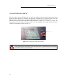
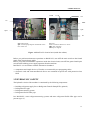
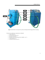
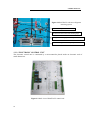
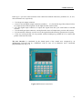
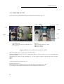
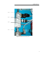
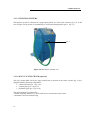
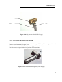
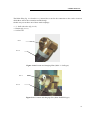
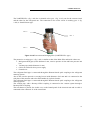
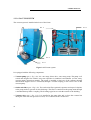
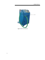

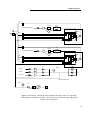
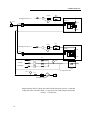
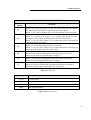
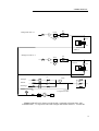

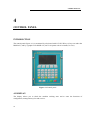
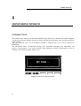
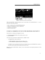
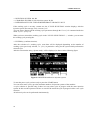
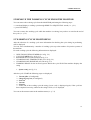
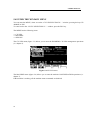
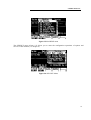
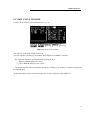
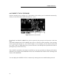
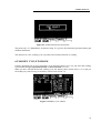

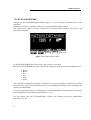
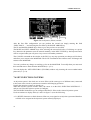
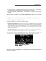
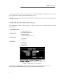
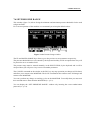
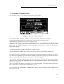
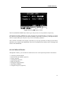
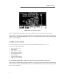
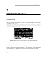


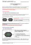

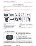
![HEMOSPRAY_JCochin 2012_DVD [Lecture seule]](http://vs1.manualzilla.com/store/data/006493407_1-a29ddfac365866d6de4c1f8c515ac468-150x150.png)