1
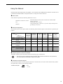
Machine Controller MP2000 Series
262IF-01
FL-net Communication Module
USER'S MANUAL
Model
JAPMC-MC2303-E
262IF-01
RUN
ERR
LNK
TX
RX
TEST
OFF
ON
FL-net
LINK
100M
FL-net Overview
1
Overview of 262IF-01 Module
2
Mounting and Starting the Module
3
FL-net Transmission Definition
4
Details of FL-net
5
Message Send and Receive Functions
6
Troubleshooting
7
Appendices
MANUAL NO. SIEP C880700 36A
App
Copyright © 2008 YASKAWA ELECTRIC CORPORATION
All rights reserved. No part of this publication may be reproduced, stored in a retrieval system, or
transmitted, in any form, or by any means, mechanical, electronic, photocopying, recording, or otherwise, without the prior written permission of Yaskawa. No patent liability is assumed with respect to
the use of the information contained herein. Moreover, because Yaskawa is constantly striving to
improve its high-quality products, the information contained in this manual is subject to change without
notice. Every precaution has been taken in the preparation of this manual. Nevertheless, Yaskawa
assumes no responsibility for errors or omissions. Neither is any liability assumed for damages resulting from the use of the information contained in this publication.
Using this Manual
Read this manual thoroughly before using 262IF-01. This manual describes MP2000 Series Machine Controller FL-net
Communication Module 262IF-01. Keep this manual in a safe place for future reference.
Basic Terms
Unless otherwise specified, the following definitions are used:
• MP2000 Series Machine Controller:
MP2100M, MP2200, MP2300, MP2310, MP2300S, and MP2500MD
Machine Controllers
• PLC:
Programmable Logic Controller
• MPE720:
The Programming Device Software or a personal computer running the Programming Device Software
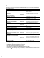
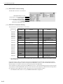
Manual Configuration
This manual consists of the chapters listed in the following table. Read the chapters of this manual as required by the
purpose.
Purpose
Selecting
Models and
Peripheral
Devices
Studying
Specifications
and Ratings
Designing
the
System
Panel
Installation
and Wiring
Trial
Operation
Maintenance
and
Inspection
Chapter 1 FL-net Overview
9
−
9
−
−
−
Chapter 2 Overview of 262IF-01
Module
9
9
9
9
9
9
Chapter 3 Mounting and Starting
the Module
−
9
9
9
9
9
Chapter 4 FL-net Transmission
Definition
−
9
9
−
9
9
Chapter 5 Details of FL-net
9
−
9
9
9
9
Chapter 6 Message Send and
Receive Functions
−
−
9
−
9
−
Chapter 7 Troubleshooting
−
9
9
9
9
9
Chapter
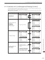
Graphic Symbols Used in this Manual
The graphic symbols used in this manual indicate the following type of information.
This symbol is used to indicate important information that should be memorized or minor precautions,
such as precautions that will result in alarms if not heeded.
Indication of Reverse Signals
In this manual, the names of reverse signals (ones that are valid when low) are written with a forward slash (/) before
the signal name, as shown in the following example:
<Notation Examples>
S-ON = /S-ON
P-CON = /P-CON
iii
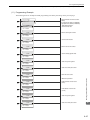
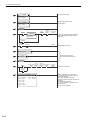
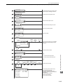
Related Manuals
The following table lists the manuals relating to the MP2000 Series Machine Controller 262IF-01 Module. Refer to
these manuals as required.
Manual Name
Contents
Machine Controller MP2100/MP2100M
User's Manual
Design and Maintenance
SIEPC88070001
Describes how to use the MP2100 and MP2100M
Machine Controllers.
Machine Controller MP2200
User's Manual
SIEPC88070014
Describes how to use the MP2200 Machine Controller and the modules that can be connected.
Machine Controller MP2300
Basic Module User's Manual
SIEPC88070003
Describes how to use the MP2300 Basic Module
and the modules that can be connected.
Machine Controller MP2310
Basic Module User’s Manual
SIEPC88073201
Describes how to use the MP2310 Basic Module
and the modules that can be connected.
Machine Controller MP2300S
Basic Module User’s Manual
SIEPC88073200
Describes how to use the MP2300S Basic Module
and the modules that can be connected.
Machine Controller MP2500/MP2500M/
MP2500D/MP2500MD User's Manual
SIEPC88075200
Describes how to use the MP2500, MP2500M,
MP2500D, and MP2500MD Machine Controllers.
Machine Controller MP2000 Series
Motion Module Built-in SVB/SVB-01
User's Manual
SIEPC88070033
Provides a detailed description on the MP2000
Series Machine Controller built-in SVB Module
and slot-mounting optional SVB-01 Module.
Machine Controller MP2000 Series
Communication Module User’s Manual
SIEPC88070004
Provides the information on the Communication
Module that can be connected to MP2000 Series
Machine Controller and the communication methods.
Machine Controller MP900/MP2000 Series
User's Manual: Ladder Programming
SIE-C887-1.2
Describes the instructions used in MP900/MP2000
ladder programming.
Machine Controller MP2000 Series User's
Manual: Motion Programming
SIEPC88070038
Describes the instructions used in MP2000 motion
programming.
Machine Controller MP2000 Series
MPE720 Programming Device Version 6
User's Manual
SIEPC88070030
Describes how to install and operate the programming tool MPE720 version 6 for MP2000 Series
Machine Controllers.
Machine Controller MP900/MP2000 Series
MPE720 Software for Programming Device
User's Manual
SIEPC88070005
Describes how to install and operate the MP900/
MP2000 Series programming system (MPE720).
Machine Controller MP900/MP2000 Series
New Ladder Editor Programming Manual
SIE-C887-13.1
Machine Controller MP900/MP2000 Series
New Ladder Editor User's Manual
SIE-C887-13.2
Machine Controller MP920
User's Manual
Communication Modules
SIE-C887-2.6
iv
Manual Number
Describes the programming instructions of the New
Ladder Editor, which assists MP900/MP2000
Series design and maintenance.
Describes the operating methods of the New Ladder
Editor, which assists MP900/MP2000 Series design
and maintenance.
Describes the functions, specifications, and application methods of the MP920 Communication Modules (217IF, 215IF, and 218IF).
Copyrights
DeviceNet is a registered trademark of the ODVA (Open DeviceNet Venders Association).
Ethernet is a registered trademark of the Xerox Corporation.
PROFIBUS is a trademark of the PROFIBUS User Organization.
MPLINK is a trademark of the Yaskawa Electric Corporation.
MECHATROLINK is a trademark of the MECHATROLINK Members Association.
Other product names and company names are the trademarks or registered trademarks of the respective company.
“TM” and the R mark do not appear with product or company names in this manual.
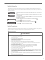
Safety Information
The following conventions are used to indicate precautions in this manual. Information marked as shown below is
important for the safety of the user. Always read this information and heed the precautions that are provided. The conventions are as follows:
WARNING
Indicates precautions that, if not heeded, could possibly result in loss of life or serious injury.
CAUTION
Indicates precautions that, if not heeded, could result in relatively serious or minor injury,
or property damage.
If not heeded, even precautions classified under
depending on circumstances.
PROHIBITED
Indicates prohibited actions. Specific prohibitions are indicated inside
For example,
MANDATORY
CAUTION can lead to serious results
indicates no fire or open flame.
Indicates mandatory actions. Specific actions are indicated inside
For example,
.
●.
indicates that grounding is required.
Safety Precautions
The following precautions are for checking products on delivery, storage, transportation, installation, wiring, operation,
application, inspection, and disposal. These precautions are important and must be observed.
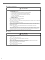
General Precautions
WARNING
Before starting operation while connected to the machine, ensure that an emergency stop procedure has
been provided and is working correctly.
There is a risk of injury.
Do not touch anything inside the product.
There is a risk of electrical shock.
Always keep the front cover attached when power is being supplied.
There is a risk of electrical shock.
Observe all procedures and precautions given in this manual for trial operation.
Operating mistakes while the Servomotor and machine are connected can cause damage to the machine or
even accidents resulting in injury or death.
Do not remove the front cover, cables, connector, or options while power is being supplied.
There is a risk of electrical shock.
Do not damage, pull on, apply excessive force to, place heavy objects on, or pinch cables.
There is a risk of electrical shock, operational failure of the product, or burning.
Do not attempt to modify the product in any way.
There is a risk of injury or device damage.
Do not approach the machine when there is a momentary interruption to the power supply. When power is
restored, the MP2000 Series Machine Controller or machine connected to it may start operation suddenly.
Provide suitable safety measures to protect people when operation restarts.
There is a risk of injury.
Do not allow installation, disassembly, or repairs to be performed by anyone other than specified personnel.
There is a risk of electrical shock or injury.
v
Storage and Transportation
CAUTION
Do not store or install the product in locations subject to the following. There is a risk of fire, electric shock,
and machine product damage.
Direct sunlight
Ambient temperatures exceeding the storage or operating conditions
Ambient humidity exceeding the storage or operating conditions
Extreme changes in temperature that would result in condensation
Corrosive or flammable gas
Excessive dust, dirt, salt, or metallic powder
Water, oil, or chemicals
Vibration or shock
Do not overload the product during transportation.
There is a risk of injury or an accident.
Never subject the product to an atmosphere containing halogen (fluorine, chlorine, bromine, or iodine) during transportation or installation.
There is a risk of device damage or an accident.
If disinfectants or insecticides must be used to treat packing materials such as wooden frames, pallets, or
plywood, the packing materials must be treated before the product is packaged, and methods other than
fumigation must be used.
Example: Heat treatment, where materials are kiln-dried to a core temperature of 56°C for 30
minutes or more.
If the electronic products, which include stand-alone products and products installed in machines, are packed
with fumigated wooden materials, the electrical components may be greatly damaged by the gases or fumes
resulting from the fumigation process. In particular, disinfectants containing halogen, which includes chlorine, fluorine, bromine, or iodine can contribute to the erosion of the capacitors.
Installation
CAUTION
Never use the product in locations subject to water, corrosive atmospheres, or flammable gas, or near
burnable objects.
There is a risk of electrical shock or fire.
Do not step on the product or place heavy objects on the product.
There is a risk of injury.
Do not block the air exhaust port on the product. Do not allow foreign objects to enter the product.
There is a risk of element deterioration inside, an accident, or fire.
Always mount the product in the specified orientation.
There is a risk of an accident.
Do not subject the product to strong shock.
There is a risk of an accident.
vi
Wiring
CAUTION
Check the wiring to be sure it has been performed correctly.
There is a risk of motor run-away, injury, or an accident.
Always use a power supply of the specified voltage.
There is a risk of burning.
In places with poor power supply conditions, take all steps necessary to ensure that the input power is supplied within the specified voltage range.
There is a risk of device damage.
Install breakers and other safety measures to provide protection against shorts in external wiring.
There is a risk of fire.
Provide sufficient shielding when using the product in the locations subject to the following.
There is a risk of device damage.
Noise, such as from static electricity
Strong electromagnetic or magnetic fields
Radiation
Near power lines
Selecting, Separating, and Laying External Cables
CAUTION
Consider the following items when selecting the I/O signal lines (external cables) to connect the product to
external devices.
Mechanical strength
Noise interference
Wiring distance
Signal voltage, etc.
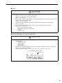
Separate the I/O signal lines from the power lines both inside and outside the control box to reduce the
influence of noise from the power lines.
If the I/O signal lines and power lines are not separated properly, malfunctioning may result.
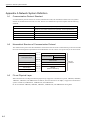
Example of Separated External Cables
Steel separator
Power circuit
cables
General
control circuit
cables
Digital I/O
signal cables
vii
Maintenance and Inspection Precautions
CAUTION
Do not attempt to disassemble the product.
There is a risk of electrical shock or injury.
Do not change wiring while power is being supplied.
There is a risk of electrical shock or injury.
Disposal Precautions
CAUTION
Dispose of the product as general industrial waste.
viii
Contents
Using this Manual - - - - - - - - - - - - - - - - - - - - - - - - - - - - - - - - - - - - - - - - - - - - - - - - - - - - - - - iii
Safety Information - - - - - - - - - - - - - - - - - - - - - - - - - - - - - - - - - - - - - - - - - - - - - - - - - - - - - - - v
Safety Precautions - - - - - - - - - - - - - - - - - - - - - - - - - - - - - - - - - - - - - - - - - - - - - - - - - - - - - - v
1 FL-net Overview - - - - - - - - - - - - - - - - - - - - - - - - - - - - - - - - - - - - - - - - - - - - 1-1
1.1 What is FL-net? - - - - - - - - - - - - - - - - - - - - - - - - - - - - - - - - - - - - - - - - - - - - - 1-2
1.2 FL-net Protocol- - - - - - - - - - - - - - - - - - - - - - - - - - - - - - - - - - - - - - - - - - - - - - 1-2
1.3 FL-net Features - - - - - - - - - - - - - - - - - - - - - - - - - - - - - - - - - - - - - - - - - - - - - 1-3
1.4 FAQ on FL-net - - - - - - - - - - - - - - - - - - - - - - - - - - - - - - - - - - - - - - - - - - - - - - 1-4
1.5 Basic FL-net Terminology - - - - - - - - - - - - - - - - - - - - - - - - - - - - - - - - - - - - - - 1-6
2 Overview of 262IF-01 Module - - - - - - - - - - - - - - - - - - - - - - - - - - - - - - - - - - - 2-1
2.1 Overview of 262IF-01 Module - - - - - - - - - - - - - - - - - - - - - - - - - - - - - - - - - - - 2-2
2.1.1
2.1.2
2.1.3
2.1.4
2.1.5
2.1.6
Module Specifications - - - - - - - - - - - - - - - - - - - - - - - - - - - - - - - - - - - - - - - - - - - - - - - - - - Appearance and Connectors - - - - - - - - - - - - - - - - - - - - - - - - - - - - - - - - - - - - - - - - - - - - - Status Indicators (LEDs)- - - - - - - - - - - - - - - - - - - - - - - - - - - - - - - - - - - - - - - - - - - - - - - - - Communication Status Indicators (LED) (Included with Ethernet Connector) - - - - - - - - - - - - Switch Settings - - - - - - - - - - - - - - - - - - - - - - - - - - - - - - - - - - - - - - - - - - - - - - - - - - - - - - - Offline Self-diagnostic Test - - - - - - - - - - - - - - - - - - - - - - - - - - - - - - - - - - - - - - - - - - - - - - - -
2-3
2-6
2-6
2-6
2-7
2-7
2.2 Connection Specifications - - - - - - - - - - - - - - - - - - - - - - - - - - - - - - - - - - - - - - 2-8
2.2.1 Connector Specifications - - - - - - - - - - - - - - - - - - - - - - - - - - - - - - - - - - - - - - - - - - - - - - - - - 2-8
2.2.2 Cable Specifications - - - - - - - - - - - - - - - - - - - - - - - - - - - - - - - - - - - - - - - - - - - - - - - - - - - - 2-8
2.3 System Configuration Example - - - - - - - - - - - - - - - - - - - - - - - - - - - - - - - - - - 2-9
2.3.1
2.3.2
2.3.3
2.3.4
Small-scale Configuration - - - - - - - - - - - - - - - - - - - - - - - - - - - - - - - - - - - - - - - - - - - - - - - - 2-9
Basic Configuration - - - - - - - - - - - - - - - - - - - - - - - - - - - - - - - - - - - - - - - - - - - - - - - - - - - - - 2-9
Locally Concentrated Device Configuration - - - - - - - - - - - - - - - - - - - - - - - - - - - - - - - - - - - 2-10
Long Distant, Locally Distributed Device Configuration - - - - - - - - - - - - - - - - - - - - - - - - - - - 2-11
3 Mounting and Starting the Module - - - - - - - - - - - - - - - - - - - - - - - - - - - - - - - - 3-1
3.1 Applicable Machine Controllers and Supported Versions - - - - - - - - - - - - - - - - 3-2
3.1.1 Applicable Machine Controllers- - - - - - - - - - - - - - - - - - - - - - - - - - - - - - - - - - - - - - - - - - - - - 3-2
3.1.2 Supported CPU and MPE720 Versions - - - - - - - - - - - - - - - - - - - - - - - - - - - - - - - - - - - - - - - 3-2
3.2 Mounting and Removing a Module on Machine Controller - - - - - - - - - - - - - - - 3-3
3.2.1 Mounting a 262IF-01 Module - - - - - - - - - - - - - - - - - - - - - - - - - - - - - - - - - - - - - - - - - - - - - - 3-3
3.2.2 Removing a 262IF-01 Module- - - - - - - - - - - - - - - - - - - - - - - - - - - - - - - - - - - - - - - - - - - - - - 3-6
3.3 Setting the Communication Manager - - - - - - - - - - - - - - - - - - - - - - - - - - - - - - 3-8
3.3.1 Opening the Communication Manager - - - - - - - - - - - - - - - - - - - - - - - - - - - - - - - - - - - - - - - 3-8
3.3.2 Setting the Communication Manager- - - - - - - - - - - - - - - - - - - - - - - - - - - - - - - - - - - - - - - - - 3-9
3.4 Self-configuration - - - - - - - - - - - - - - - - - - - - - - - - - - - - - - - - - - - - - - - - - - - - 3-19
3.4.1 Executing Self-configuration - - - - - - - - - - - - - - - - - - - - - - - - - - - - - - - - - - - - - - - - - - - - - - 3-19
3.5 Starting the MPE720 and Setting Communication or Network Parameters - - - - 3-20
3.5.1 Starting MPE720 Ver. 6 and Setting Communication- - - - - - - - - - - - - - - - - - - - - - - - - - - - - 3-20
3.5.2 Starting MPE720 Ver. 5. and Setting the Network - - - - - - - - - - - - - - - - - - - - - - - - - - - 3-21
ix
4 FL-net Transmission Definition - - - - - - - - - - - - - - - - - - - - - - - - - - - - - - - - - - 4-1
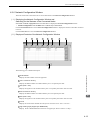
4.1 Displaying the FL-net Transmission Configuration Window- - - - - - - - - - - - - - - - 4-2
4.1.1 Displaying the Module Configuration Window - - - - - - - - - - - - - - - - - - - - - - - - - - - - - - - - - - 4-2
4.1.2 Displaying the FL-net Transmission Configuration Window
from the Module Configuration Window - - - - - - - - - - - - - - - - - - - - - - - - - - - - - - - - - - - - - - 4-3
4.2 FL-net Transmission Definition- - - - - - - - - - - - - - - - - - - - - - - - - - - - - - - - - - - - 4-4
4.2.1
4.2.2
4.2.3
4.2.4
4.2.5
4.2.6
4.2.7
Transmission Parameters Tab Page - - - - - - - - - - - - - - - - - - - - - - - - - - - - - - - - - - - - - - - - - 4-4
Link Assignment Tab Page - - - - - - - - - - - - - - - - - - - - - - - - - - - - - - - - - - - - - - - - - - - - - - - 4-6
Link Status Tab Page - - - - - - - - - - - - - - - - - - - - - - - - - - - - - - - - - - - - - - - - - - - - - - - - - - - 4-9
Status Detail Window - - - - - - - - - - - - - - - - - - - - - - - - - - - - - - - - - - - - - - - - - - - - - - - - - - 4-10
Status Tab Page - - - - - - - - - - - - - - - - - - - - - - - - - - - - - - - - - - - - - - - - - - - - - - - - - - - - - - 4-12
Network Configuration Window - - - - - - - - - - - - - - - - - - - - - - - - - - - - - - - - - - - - - - - - - - - 4-13
Saving FL-net Transmission Definitions - - - - - - - - - - - - - - - - - - - - - - - - - - - - - - - - - - - - - 4-14
5 Details of FL-net - - - - - - - - - - - - - - - - - - - - - - - - - - - - - - - - - - - - - - - - - - - - 5-1
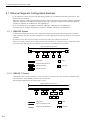
5.1 Ethernet Segment Configuration Example - - - - - - - - - - - - - - - - - - - - - - - - - - - 5-2
5.1.1
5.1.2
5.1.3
5.1.4
10BASE5 System - - - - - - - - - - - - - - - - - - - - - - - - - - - - - - - - - - - - - - - - - - - - - - - - - - - - - 10BASE-T System - - - - - - - - - - - - - - - - - - - - - - - - - - - - - - - - - - - - - - - - - - - - - - - - - - - - 100BASE-TX system - - - - - - - - - - - - - - - - - - - - - - - - - - - - - - - - - - - - - - - - - - - - - - - - - - Ethernet IP Address - - - - - - - - - - - - - - - - - - - - - - - - - - - - - - - - - - - - - - - - - - - - - - - - - - - -
5-2
5-2
5-3
5-4
5.2 About FL-net - - - - - - - - - - - - - - - - - - - - - - - - - - - - - - - - - - - - - - - - - - - - - - - - 5-5
5.2.1 FL-net Overview - - - - - - - - - - - - - - - - - - - - - - - - - - - - - - - - - - - - - - - - - - - - - - - - - - - - - - - 5-5
5.3 FL-net Data Communication - - - - - - - - - - - - - - - - - - - - - - - - - - - - - - - - - - - - - 5-9
5.3.1 Cyclic Transmission - - - - - - - - - - - - - - - - - - - - - - - - - - - - - - - - - - - - - - - - - - - - - - - - - - - - 5-9
5.3.2 Message Transmission - - - - - - - - - - - - - - - - - - - - - - - - - - - - - - - - - - - - - - - - - - - - - - - - - 5-12
5.3.3 Details of Supported Messages - - - - - - - - - - - - - - - - - - - - - - - - - - - - - - - - - - - - - - - - - - - 5-14
6 Message Send and Receive Functions - - - - - - - - - - - - - - - - - - - - - - - - - - - - 6-1
6.1 Message Send Function - - - - - - - - - - - - - - - - - - - - - - - - - - - - - - - - - - - - - - - - 6-2
6.1.1
6.1.2
6.1.3
6.1.4
6.1.5
6.1.6
6.1.7
Outline Specifications - - - - - - - - - - - - - - - - - - - - - - - - - - - - - - - - - - - - - - - - - - - - - - - - - - - 6-2
MSG-SND Function Setting Example - - - - - - - - - - - - - - - - - - - - - - - - - - - - - - - - - - - - - - - - 6-3
Inputs and Outputs for the Message Send Function - - - - - - - - - - - - - - - - - - - - - - - - - - - - - - 6-3
Parameter List for MSG-SND Function - - - - - - - - - - - - - - - - - - - - - - - - - - - - - - - - - - - - - - - 6-9
Parameter Details for MSG-SND Function - - - - - - - - - - - - - - - - - - - - - - - - - - - - - - - - - - - 6-10
Specifying an FL-net Virtual Address Space Using the MSG-SND Function - - - - - - - - - - - - 6-15
Relationship among the Data Address, Data Size, and Offset
in the MSG-SND Function - - - - - - - - - - - - - - - - - - - - - - - - - - - - - - - - - - - - - - - - - - - - - - - 6-16
6.2 Message Receive Function - - - - - - - - - - - - - - - - - - - - - - - - - - - - - - - - - - - - - 6-17
6.2.1
6.2.2
6.2.3
6.2.4
6.2.5
6.2.6
Basic Specifications - - - - - - - - - - - - - - - - - - - - - - - - - - - - - - - - - - - - - - - - - - - - - - - - - - MSG-RCV Function Setting Example - - - - - - - - - - - - - - - - - - - - - - - - - - - - - - - - - - - - - - Inputs and Outputs for the Message Receive Function - - - - - - - - - - - - - - - - - - - - - - - - - - Parameter List for MSG-RCV Function - - - - - - - - - - - - - - - - - - - - - - - - - - - - - - - - - - - - - Parameter Details for MSG-RCV Function - - - - - - - - - - - - - - - - - - - - - - - - - - - - - - - - - - Relationship among the Data Address, Data Size, and Offset in the MSG-RCV Function - -
6-17
6-18
6-18
6-23
6-24
6-28
6.3 Combination of FL-net Messages and Message Functions - - - - - - - - - - - - - - - 6-29
6.4 Displaying a Register List and Notes at Register Input - - - - - - - - - - - - - - - - - - 6-30
6.4.1 Displaying a Register List - - - - - - - - - - - - - - - - - - - - - - - - - - - - - - - - - - - - - - - - - - - - - - - 6-30
6.4.2 Notes at Register Input - - - - - - - - - - - - - - - - - - - - - - - - - - - - - - - - - - - - - - - - - - - - - - - - - 6-32
6.5 Programming Example - - - - - - - - - - - - - - - - - - - - - - - - - - - - - - - - - - - - - - - - 6-33
6.5.1 Word Block Data Read (Client) - - - - - - - - - - - - - - - - - - - - - - - - - - - - - - - - - - - - - - - - - - - 6-33
6.5.2 Word Block Data Write (Client)- - - - - - - - - - - - - - - - - - - - - - - - - - - - - - - - - - - - - - - - - - - - 6-36
x
6.5.3 Word Block Data Read/Write (Server) - - - - - - - - - - - - - - - - - - - - - - - - - - - - - - - - - - - - - - 6.5.4 Sending Request (Client)/Response (Server)
according to Non-procedure Protocol - - - - - - - - - - - - - - - - - - - - - - - - - - - - - - - - - - - - - - 6.5.5 Sending Request/Receiving Response (Client)
according to Non-procedure Protocol - - - - - - - - - - - - - - - - - - - - - - - - - - - - - - - - - - - - - - 6.5.6 Receiving Transparent Message Request (Server) - - - - - - - - - - - - - - - - - - - - - - - - - - - - - -
6-39
6-42
6-45
6-51
7 Troubleshooting - - - - - - - - - - - - - - - - - - - - - - - - - - - - - - - - - - - - - - - - - - - - - 7-1
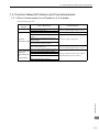
7.1 Before Starting to Locate Faults - - - - - - - - - - - - - - - - - - - - - - - - - - - - - - - - - - 7-2
7.2 Common Network Problems and Countermeasures- - - - - - - - - - - - - - - - - - - - 7-3
7.2.1
7.2.2
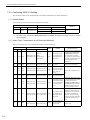
7.2.3
7.2.4
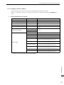
When Communication Is not Possible or It Is Unstable - - - - - - - - - - - - - - - - - - - - - - - - - - - Confirming 262IF-01 Setting - - - - - - - - - - - - - - - - - - - - - - - - - - - - - - - - - - - - - - - - - - - - - - System I/O Error Status - - - - - - - - - - - - - - - - - - - - - - - - - - - - - - - - - - - - - - - - - - - - - - - - - Details on I/O Error Status - - - - - - - - - - - - - - - - - - - - - - - - - - - - - - - - - - - - - - - - - - - - - - - -
7-3
7-4
7-5
7-9
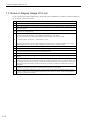
7.3 Notes on Regular Usage of FL-net - - - - - - - - - - - - - - - - - - - - - - - - - - - - - - - - 7-12
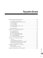
Appendices - - - - - - - - - - - - - - - - - - - - - - - - - - - - - - - - - - - - - - - - - - - - - - - - A-1
Appendix A Network System Definition - - - - - - - - - - - - - - - - - - - - - - - - - - - - - - - A-2
A.1
A.2
A.3
A.4
A.5
A.6
A.7
A.8
Communication Protocol Standard- - - - - - - - - - - - - - - - - - - - - - - - - - - - - - - - - - - - - - - - - - - Hierarchical Structure of Communication Protocol- - - - - - - - - - - - - - - - - - - - - - - - - - - - - - - - FL-net Physical Layer - - - - - - - - - - - - - - - - - - - - - - - - - - - - - - - - - - - - - - - - - - - - - - - - - - - FL-net IP Address - - - - - - - - - - - - - - - - - - - - - - - - - - - - - - - - - - - - - - - - - - - - - - - - - - - - - - FL-net Subnet Mask- - - - - - - - - - - - - - - - - - - - - - - - - - - - - - - - - - - - - - - - - - - - - - - - - - - - - TCP/IP, UDP/IP Communication Protocol- - - - - - - - - - - - - - - - - - - - - - - - - - - - - - - - - - - - - - FL-net Port Number - - - - - - - - - - - - - - - - - - - - - - - - - - - - - - - - - - - - - - - - - - - - - - - - - - - - - FL-net Data Format - - - - - - - - - - - - - - - - - - - - - - - - - - - - - - - - - - - - - - - - - - - - - - - - - - - - - -
A-2
A-2
A-2
A-3
A-3
A-4
A-4
A-5
Appendix B FL-net Network Management - - - - - - - - - - - - - - - - - - - - - - - - - - - - - A-7
B.1
B.2
B.3
B.4
B.5
B.6
B.7
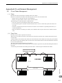
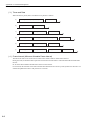
FL-net Token Management - - - - - - - - - - - - - - - - - - - - - - - - - - - - - - - - - - - - - - - - - - - - - - - - - A-7
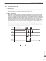
Joining/Leaving FL-net - - - - - - - - - - - - - - - - - - - - - - - - - - - - - - - - - - - - - - - - - - - - - - - - - - - - A-9
Node Status Management - - - - - - - - - - - - - - - - - - - - - - - - - - - - - - - - - - - - - - - - - - - - - - - - A-11
FL-net Local Node Management Table - - - - - - - - - - - - - - - - - - - - - - - - - - - - - - - - - - - - - - - A-11
FL-net Join Node Management Table - - - - - - - - - - - - - - - - - - - - - - - - - - - - - - - - - - - - - - - - A-12
FL-net Status Management- - - - - - - - - - - - - - - - - - - - - - - - - - - - - - - - - - - - - - - - - - - - - - - - A-13
FL-net Message Serial Number Management- - - - - - - - - - - - - - - - - - - - - - - - - - - - - - - - - - - A-13
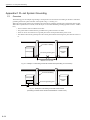
Appendix C FL-net System Grounding - - - - - - - - - - - - - - - - - - - - - - - - - - - - - - - A-14
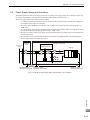
C.1
C.2
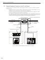
C.3
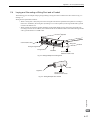
C.4
C.5
Overview - - - - - - - - - - - - - - - - - - - - - - - - - - - - - - - - - - - - - - - - - - - - - - - - - - - - - - - - - - - Power Supply Wiring and Grounding - - - - - - - - - - - - - - - - - - - - - - - - - - - - - - - - - - - - - - - - Network Equipment Connection in the FL-net System- - - - - - - - - - - - - - - - - - - - - - - - - - - - Laying and Grounding a Wiring Duct and a Conduit - - - - - - - - - - - - - - - - - - - - - - - - - - - - - FL-net Construction Work Check Sheet - - - - - - - - - - - - - - - - - - - - - - - - - - - - - - - - - - - - - - -
A-14
A-15
A-16
A-17
A-18
Appendix D Supplement on FL-net Profile - - - - - - - - - - - - - - - - - - - - - - - - - - - - A-19
D.1 262IF-01 Profile- - - - - - - - - - - - - - - - - - - - - - - - - - - - - - - - - - - - - - - - - - - - - - - - - - - - - - - - A-19
D.2 ANS.1 Transfer Syntax Summary - - - - - - - - - - - - - - - - - - - - - - - - - - - - - - - - - - - - - - - - - - - A-20
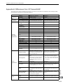
Appendix E Differences from CP Series/262IF - - - - - - - - - - - - - - - - - - - - - - - - - A-23
INDEX - - - - - - - - - - - - - - - - - - - - - - - - - - - - - - - - - - - - - - - - - - - - - - - - - Index-1
Revision History
xi
1
FL-net Overview
This chapter gives an overview of FL-net.
For details on FL-net, refer to Chapter 5 Details of FL-net.
1.1 What is FL-net? - - - - - - - - - - - - - - - - - - - - - - - - - - - - - - - - - - - - - - - - - -1-2
1.2 FL-net Protocol - - - - - - - - - - - - - - - - - - - - - - - - - - - - - - - - - - - - - - - - - - -1-2
1.3 FL-net Features - - - - - - - - - - - - - - - - - - - - - - - - - - - - - - - - - - - - - - - - - -1-3
1.4 FAQ on FL-net - - - - - - - - - - - - - - - - - - - - - - - - - - - - - - - - - - - - - - - - - - -1-4
FL-net Overview
1.5 Basic FL-net Terminology - - - - - - - - - - - - - - - - - - - - - - - - - - - - - - - - - - -1-6
1
1-1
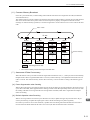
1.1 What is FL-net?
1.1 What is FL-net?
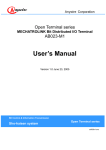
As shown in Fig. 1.1, FL-net is a network capable of interconnecting various FA controllers such as the programmable
controllers (PLC) and computer numeric control equipment (CNC) from many manufacturers, and personal computers
for control and monitoring.
PC
PC
PC
Server
EWS
Computer
WAN
Upper LAN Ethernet 䋨TCP/IP, UDP/IP䋩
FL-net (Ethernet-based control network)
PLC
MP2300
SVB-01 218IF-02 262IF-01
PLC
MP2200
Panel
controller
PLC
CNC
CPU-02 SVB-01 218IF-02 262IF-01 LIO-04 LIO-04 LIO-04 LIO-01 LIO-01
Controller
Field network
Equipment
Sensor actuator
Fig. 1.1 Example of FA Control Network Configuration
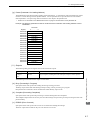
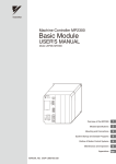
1.2 FL-net Protocol
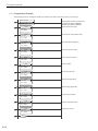
The following shows a basic FL-net protocol structure.
Application layer
Controller or interface
Service function
Cyclic transmission
FA link protocol layer
Message transmission
Token function
Transport layer
UDP
Network layer
IP
Data link layer
Ethernet
(Based on IEEE802.3)
Physical layer
Fig. 1.2 Basic FL-net Protocol Structure
The transport and network layers use UDP/IP, while the data link and physical layers use Ethernet.
1-2
FL-net
protocol
RC
1.3 FL-net Features
1.3 FL-net Features
FL-net has the following features:
• Open control network
• Realization of multi-vendor environments
• FL-net is capable of interconnecting controllers such as the programmable controllers (PLC) and computer
numeric control equipment (CNC) from many manufacturers, and personal computers for control and monitoring.
In addition, FL-net has the following features.
Compliant with Worldwide Standards
Efficient communication based on standard UDP/IP is realized as well as de facto standard Ethernet for OA equipment
communication. Ethernet provides the following advantages.
– Low cost
Prevailing communication devices can be used, resulting in low cost.
– Availability of prevailing network devices
A wide variety of prevailing network devices such as transceivers, hubs, cables, and PC LAN cards for Ethernet
can be used.
– Realization of high-speed communication
In the future, the baud rate can be increased to support 10 Mbps, 100 Mbps, and 1 Gbps.
– Communication via optical fiber cables
The prevailing Ethernet optical repeater allows optical fibers to be used in the corresponding section for communication over distances of 500 m or more, improves noise resistance, and prevents of surge currents caused by
lightning strikes in outside wiring.
Support of Necessary Communication Functions between FA Controllers
Because user requirements are fully examined as specifications, various features required for FA are supported.
– Large network
– Support of two types of communication functions according to purpose
The common memory function allows each node to share the same data through cyclic communication, and the
message communication function allows only necessary information to be transferred on demand.
– Large common memory
A large common memory (8 kbits + 8 kwords) is supported.
– Fast response
FL-net Overview
A maximum of 254 pieces of equipment (nodes) can be connected.
1
A fast response of 50 ms/32 nodes (2 kbits +2 kwords) can be realized.
– High reliability by masterless system
Because no master station is needed, each node can join or leave without affecting communications between
other nodes. Thus, each node can be turned ON or OFF and maintained independently.
1-3
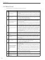
1.4 FAQ on FL-net
1.4 FAQ on FL-net
The following gives a list of frequently asked questions and answers.
Question
1
What is Ethernet?
2
What is FL-net?
FL-net refers to a network capable of interconnecting FA controllers such as programmable controllers (PLC) and computer numeric control (CNC) equipment so as to transfer control data at high speed between controllers.
Cables are identical to those employed for Ethernet.
What is the difference between
FL-net and Ethernet?
Ethernet is used to connect controllers to the host computer or PC so that production
directions can be given or performance information can be obtained for informational or
control purposes. On the other hand, FL-net is used to connect controllers for highspeed control data transfer.
When one controller is used for both an FL-net to connect controllers and an Ethernet to
connect controllers to the host devices, care should be taken for correct cable connection.
4
How should we use the FN-net
unit?
The FL-net unit should be installed in FA controllers such as a programmable controller
(PLC) and computer numeric control (CNC) equipment so that data transfer can take
place cyclically between the controllers as long as link assignments for station numbers
(node numbers) and common memory (also called “link register”) are simply made in
the same manner as for regular PLC CPU link units. In this case, no special communication program is required for PLC, etc. In addition, when PLC memory contents or
communication parameters are read or written from PC, no special communication program is required for PLC, etc.
However, note that each controller should be provided with a communication program
when data transfer is attempted between controllers through message transmission.
5
What is a protocol?
What protocol is supported by
FL-net?
Protocol refers to a set of rules required for communication.
FL-net employs an FL-net-dedicated FA link protocol that lies in the UDP/IP or upper
layers.
Does FL-net allow general PC
connections?
The FL-net units to be installed in FA controllers such as a programmable controller
(PLC) and computer numeric control (CNC) equipment are intelligent units with processors on their boards. Because PC Ethernet cards are non-intelligent cards called
“dumb cards,” it is generally recommended to use FL-net boards according to PC performance and usage.
What is topology?
A networking topology refers to a network wiring method. Though star (tree), bus, and
ring topologies are available as main topologies, they can be understood more easily
from a viewpoint of logical wiring rather than physical wiring.
A star topology is used for 10BASE-T/100BASE-TX in FL-net. On the other hand, a
bus topology is used for 10BASE5 in FL-net.
8
What types of network cables
are available? How long are
the cables and how many
nodes can be connected to
them?
The following summarizes the standards, characteristics, and restrictions of the most
popular Ethernet cables.
• 10BASE-T/100BASE-TX: Twisted pair cable (UTP), maximum transmission distance per segment: 100 m (500 m), maximum number of connectable nodes per segment: 254
• 10BASE5: Thick coaxial cable (yellow cable), maximum transmission distance per
segment: 500 m (2,500 m), maximum number of connectable nodes per segment: 100
(254)
• 10BASE-FL/100BASE-FX: Optical fiber cable, maximum transmission distance per
segment: 2,000 m, maximum number of connectable nodes per segment: 254
∗ Values in ( ) assume the use of repeaters.
9
When a system uses FL-net,
does it need a special Ethernet?
No. To build an FL-net system, Ethernet is used (which is formally compliant with
IEEE802.3). Special specifications are not required.
10
How should we make FL-net
connections?
Different types of Ethernet media can be interconnected with Ethernet cables through
repeaters, media conversion adaptors, etc. These products can be purchased from many
vendors.
3
6
7
1-4
Answer
Ethernet refers to a cable type specification, and is available with local area networks
(LAN). Ethernet enables data transfer between computers at a baud rate from 10 Mbps
to 100 Mbps.
Presently, the prevailing Ethernet cable for office automation is a 100-Mbp twisted pair
cable (UTP). Ethernet allows communication through the use of multi-vendor software
protocols.
1.4 FAQ on FL-net
Answer
What cable should be used to
build an FL-net system?
Generally, cables should be used as follows.
• 10BASE5 (thick coaxial cable: yellow cable) is used for the backbone.
• 10BASE-T/100BASE-TX (twisted pair cable: UTP category 5) is used for cabling in
control panels and offices.
• 10BASE-FL/100-BASE-FX (optical fiber cable) is used for cabling near high-voltage power supplies or places affected by electrical noise.
12
How should we set FL-net IP
addresses?
The FL-net IP addresses are:
Network address: 192.168.250,
Host number (node number): 1 to 254
These settings are standard. Note that numbers 250 to 254 have been reserved for use by
maintenance tools.
13
How conformance and interconnectivity have been
assured among FL-net support
devices?
There is an FL-net certification organization that conducts conformance and interconnectivity tests. Because certificates are issued to devices that have passed the tests, they
can be used safely.
11
FL-net Overview
(cont’d)
Question
1
1-5
1.5 Basic FL-net Terminology
1.5 Basic FL-net Terminology
The following gives an overview of basic FL-net terminology.
FA equipment
Refers to an FA system component device connected to FL-net. Control equipment (controllers) such as the programmable controller (PLC), computer numeric control (CNC) equipment, and personal computer (PC) are all
classified as FA equipment.
Network
Refers to a local area network (LAN) whose data link level complies with IEEE802.3 in FL-net. The existing
standard supports a baud rate of 10 Mbps in both 10BASE5 and 10BASE-T.
Node
Refers to FA equipment connected to FL-net. Each node is assigned a node number (1 to 254) for identification.
Communication unit
Generally, refers to a set of a communication board and communication module necessary for communication via
FL-net.
Networking equipment
Refers to IEEE802.3-compliant communication devices such as communication cables, transceivers, and hubs
necessary for communication via FL-net.
Switching hub
Refers to a hub (line concentrator) equipped with a bridge function. A received packet is temporarily stored in the
buffer for regenerative relaying.
Repeater hub
Refers to a hub (line concentrator) equipped with functions for electrically regenerating and relaying transmission signals on cables.
1-6
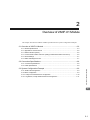
2
Overview of 262IF-01 Module
This chapter describes the 262IF-01 Module specifications and system configuration examples.
2.1 Overview of 262IF-01 Module - - - - - - - - - - - - - - - - - - - - - - - - - - - - - - - -2-2
2.1.1 Module Specifications - - - - - - - - - - - - - - - - - - - - - - - - - - - - - - - - - - - - - - - - - - - - - - 2-3
2.1.2 Appearance and Connectors - - - - - - - - - - - - - - - - - - - - - - - - - - - - - - - - - - - - - - - - - 2-6
2.1.3 Status Indicators (LEDs) - - - - - - - - - - - - - - - - - - - - - - - - - - - - - - - - - - - - - - - - - - - - - 2-6
2.1.4 Communication Status Indicators (LED) (Included with Ethernet Connector) - - - - - - - - 2-6
2.1.5 Switch Settings - - - - - - - - - - - - - - - - - - - - - - - - - - - - - - - - - - - - - - - - - - - - - - - - - - - 2-7
2.1.6 Offline Self-diagnostic Test - - - - - - - - - - - - - - - - - - - - - - - - - - - - - - - - - - - - - - - - - - - 2-7
2.2 Connection Specifications - - - - - - - - - - - - - - - - - - - - - - - - - - - - - - - - - - -2-8
2.2.1 Connector Specifications - - - - - - - - - - - - - - - - - - - - - - - - - - - - - - - - - - - - - - - - - - - - 2-8
2.3 System Configuration Example - - - - - - - - - - - - - - - - - - - - - - - - - - - - - - -2-9
2.3.1 Small-scale Configuration - - - - - - - - - - - - - - - - - - - - - - - - - - - - - - - - - - - - - - - - - - - 2-9
2.3.2 Basic Configuration - - - - - - - - - - - - - - - - - - - - - - - - - - - - - - - - - - - - - - - - - - - - - - - - 2-9
2.3.3 Locally Concentrated Device Configuration - - - - - - - - - - - - - - - - - - - - - - - - - - - - - - 2-10
2.3.4 Long Distant, Locally Distributed Device Configuration - - - - - - - - - - - - - - - - - - - - - - 2-11
Overview of 262IF-01 Module
2.2.2 Cable Specifications - - - - - - - - - - - - - - - - - - - - - - - - - - - - - - - - - - - - - - - - - - - - - - - 2-8
2
2-1
2.1 Overview of 262IF-01 Module
2.1 Overview of 262IF-01 Module
The 262IF-01 has been designed as a communication module for connecting to FL-net via an Ethernet interface
(100BASE-TX or 10BASE-T). FL-net allows this module to be connected to equipment of other manufacturers.
The 262IF-01 supports FL-net (OPCN-2) Version 2.0.
Notes on 262IF-01
The 262IF-01 Module has been designed as a communication module dedicated for use in FL-net. Note the following points:
1
The 262IF-01 cannot be connected to a regular Ethernet from the 218IF-01 or 218IF-02.
Though the 262IF-01 Module uses a standard Ethernet cable, it does not allow connection for communications based on general-purpose TCP/IP or UDP/IP because it serves only as an FL-net-dedicated module.
MP2300 controller
MP2200 controller
218IF-01
218IF-02
Ethernet
MPE720
2
262IF-01
The MPE720 engineering tool cannot be connected to the 262IF-01 directly.
When connecting the MPE720, separately prepare a module with any of the RS232C, Ethernet, and CP-215 ports for connection.
Ethernet
MPE720
3
262IF-01
No serial port (RS-232C) has been mounted.
There is no serial port
(RS-232C).
262IF-01
2-2
2.1 Overview of 262IF-01 Module
2.1.1 Module Specifications
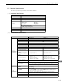
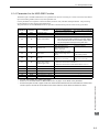
2.1.1 Module Specifications
This section provides the specifications of the 262IF-01 Module.
( 1 ) Hardware Specifications
Item
Specifications
Name
262IF-01
Model Number
JAPMC-CM2303-E
Communication Port
FL-net: 1 port
Module status indicators LED
RUN (green)
Indicators
ERR (red)
LNK (green)
RX (green)
TX (green)
FL-net status indicator LED
LINK (orange), 100M (green)
Switch
TEST
Dimensions (mm)
125 × 95 mm (H × D)
Mass
80 g
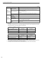
( 2 ) Transmission Specifications
Item
Specifications
100BASE-TX
10BASE-T
RJ-45 connector
Interface
IEEE802.3u
IEEE802.3i
Media Access Mode
CSMA/CD
Communication Mode
Full duplex/half duplex
Modulation Method
Baseband
Transmission Path Type
Ethernet
Transmission
Specifications
Star topology
Baud Rate
100 Mbps
10 Mbps
Maximum Number of
Cascade Connections
2 layers
4 layers
Transmission Path
Length
(Full length at repeater
usage)
100 m (205 m max.*1)
100 m (500 m max.*1)
Transmission Media
Twisted pair cable (UTP)
Category 5 or 5e
Twisted pair cable (STP)
Category 5 or 5e (100 W)
Twisted pair cable (UTP)
Category 3, 4, 5, or 5e
Twisted pair cable (STP)
Category 3, 4, 5, or 5e (100 W)
Maximum Segment
Length
100 m (distance between hub and node at UTP usage)
Support for auto-negotiation
(not possible to fix transmission and communication modes)
Link Function
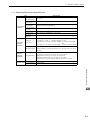
Overview of 262IF-01 Module
Compliance Standard
2
Support for Auto MDI/MDI-X
FL-net
Specifications
Transmission Control
System
Token passing
IP Address
Class C is used.
192. 168. 250. is used as standard ( indicates a number from 1 to
254 and corresponds to a node number).
Port Number
For receiving: 3 ports (55000, 55001, and 55002) are used by the system.
For sending: 1 port (55003) is used by the system.
Protocol
FA link protocol
Version
2.0
2-3
2.1 Overview of 262IF-01 Module
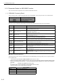
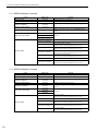
2.1.1 Module Specifications
(cont’d)
Item
Number of Nodes
Cyclic
Transmission
Specifications
Message
Transmission
Specifications
Specifications
Up to 254 nodes (at repeater usage)
(262IF-01 I/O can be assigned to 64 nodes only including the self-node.) *2
Maximum Data Size
Within network:
Area 1 (bit data): 8 kbits
Area 2 (word data): 8 kwords
Per station:
Area 1 + area 2: Area allocation is allowed up to 8 kbits + 8 kwords.
Data Exchange
N:N
Number of Message
Channels
10
Engineering
Communication
Not supported
Word block read, word block write, network parameter read, network parameter
Message Service
Number of Transmission
Words
write*3, stop command*3, start command*3,
profile read, transparent message, log data read, log data clear, message loopback
Up to 512 words
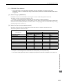
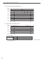
∗ 1. The cable length restriction in repeater (repeater hub or switching hub) usage varies depending on a selected
baud rate.
For repeater or switching hubs, use a commercially available hub for Ethernet. Hubs manufactured by the Japan
Electrical Manufacturer’s Association (JEMA) are recommended.
• Restrictions on 100BASE-TX connection
When Repeater Hub Is
Connected
Item
Cable length between node and
hub
100 m or less
When Switching Hub Is
Connected
100 m or less
Cable length between hubs
5 m or less
100 m or less
Number of hubs between nodes
Up to 2 hubs
Not limited
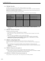
• Restrictions on 10BASE-T connection
Item
Cable length between node and
hub
When Repeater Hub Is
Connected
100 m or less
When Switching Hub Is
Connected
100 m or less
Cable length between hubs
100 m or less
100 m or less
Number of hubs between nodes
Up to 4 hubs
Not limited
∗ 2. The I/O assignment restriction, which defines that the maximum number of nodes as 64 nodes including the selfnode, is based on MP Series Machine Controller specifications.
∗ 3. A message can be only sent from the client. (Client: Data sending side, Server: Data receiving side)
2-4
2.1 Overview of 262IF-01 Module
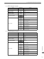
2.1.1 Module Specifications
( 3 ) Operating Environment Specifications
Item
Environmental
Conditions
Specifications
Ambient Operating Temperature
0 to +55 °C
Ambient Storage
Temperature
–25 to +85 °C
Ambient Operating Humidity
30% to 95% (with no condensation)
Ambient Storage
Humidity
5% to 95% (with no condensation)
Pollution Level
Pollution level: 2 (conforming to JIS B3502)
Corrosive Gas
There must be no combustible or corrosive gas.
Operating
Altitude
2,000 m above sea level or lower
Conforming to JIS B3502
(3) Frequency: 57 to 150 Hz Vibration strength: 9.8 m/s2 of fixed acceleration
Conforming to JIS B3502
Shock Resistance
Electrical
Operating
Conditions
Installation
Requirements
(1) Frequency: 16.7 Hz
Vibration strength: 14.7 m/s2
(2) Frequency: 10 to 57 Hz Vibration strength: 0.075 mm of single-ampli
tude
Peak acceleration of 147 m/s2 (15G) twice for 11 ms each in the X, Y, and Z
directions
Noise Resistance
Conforming to EN 61000-6-2, EN 55011 (Group 1 Class A)
Power supply noise (FT noise): ±2 kV min., for one minute
Radiation noise (FT noise): ±1 kV min., for one minute
Ground noise (impulse noise): ±1 kV min., for ten minutes
Electrostatic noise (contact discharge method): ±6 kV min., ten times
Ground
Ground to 100Ω max.
Cooling Method
Natural cooling
Overview of 262IF-01 Module
Mechanical
Operating
Conditions
Vibration
Resistance
2
2-5
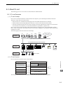
2.1 Overview of 262IF-01 Module
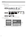
2.1.2 Appearance and Connectors
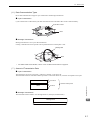
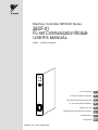
2.1.2 Appearance and Connectors
The following diagram shows the appearance of the 262IF-01 Module and gives the external dimensions of the connectors.
(25)
Status indicators
(LEDs)
262IF-01
RUN
ERR
LNK
Switches
TX
RX
TEST
OFF
FL-net connector
100Base-TX/10Base-T
01
ON
FL-net
LINK
Communication status
indicator (LED)
(included with connector)
100M
Unit: mm
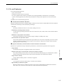
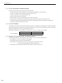
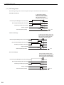
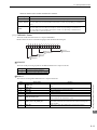
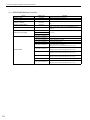
2.1.3 Status Indicators (LEDs)
The following table shows the status of the 262IF-01 Module shown by the LED indicators.
RUN
ERR
Indicator
Color
RUN
Green
ERR
Red
LNK
TX
RX
Meaning When Lit
RX
Meaning When Not Lit
–
An error has occurred.
–
• When RUN is lit:
Parameter setting error
• When RUN is not lit:
Hardware error
Normal
Green
Joining FL-net
–
Not joining FL-net
Green
Sending data
–
Not sending data
Green
Receiving data
–
Not receiving data
LNK
TX
Meaning When Blinking
Operating normally
2.1.4 Communication Status Indicators (LED) (Included with Ethernet Connector)
The indicators (LEDs) included with the Ethernet connector show the status of Ethernet communication.
Indicator
2-6
Color
LINK
Yellow
100M
Green/orange
Meaning When Lit
Meaning When Not Lit
FL-net link established.
FL-net link not established.
Green: 100 Mbps
(Orange: 1 Gbps)
10 Mbps or not connected
2.1 Overview of 262IF-01 Module
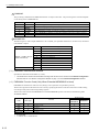
2.1.5 Switch Settings
2.1.5 Switch Settings
The following table shows the 262IF-01 Module switch settings.
Label
(Switch No.)
–
(2)
Name
ON
–
OFF
TEST
OFF
Status
ON
ON
TEST
(1)
Operating Mode
Selection
Function
–
OFF
Test Mode
Normal operation mode
OFF
Factory
Setting
Leave this switch set to OFF except
when performing the self-diagnosis
test.
OFF
Always leave the unused switches (3 and 4) set to OFF.
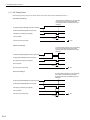
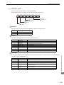
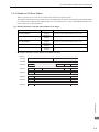
2.1.6 Offline Self-diagnostic Test
The offline self-diagnostic test will be performed if the power is turned ON when the TEST switch is set to ON and all
other switches are set to OFF. When the self-diagnostic test is performed successfuly, RUN will be lit, ERR will be lit,
and all other indicators will be unlit repeatedly in this order. The indicators will be as shown in the following table if
the offline self-diagnostic test finds a problem in the 262IF-01 Module.
Error
Indicator Status When Error Is Detected
RUN
ROM Check Error
RAM Check Error
DRAM Check Error
LAN/IF Check Error
Not lit
ERR
Blinking (1)
Blinking (2)
Blinking (3)
TX
RX
Not lit
Not lit
Blinking (4)
Overview of 262IF-01 Module
The number in parentheses following "Blinking" indicates the number of blinks.
2
2-7
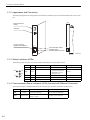
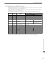
2.2 Connection Specifications
2.2.1 Connector Specifications
2.2 Connection Specifications
2.2.1 Connector Specifications
This section provides the connector specifications for the 262IF-01 Module.
( 1 ) Connector Specifications
Connector
Shape
Name
Connector Model
Connector Name No. of Pins
FL-net
LINK
FL-net
FL-net
8
Module
Cable
Manufacturer
JOG-0001NL
(LED/Pulse
transformer builtin modular jack)
Pulse Engineering
100M
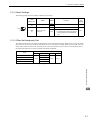
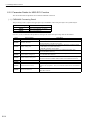
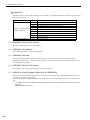
( 2 ) Connector Pin Arrangement
The connector is used to connect the MP2000 Series Machine Controller to the devices on the FL-net via an FL-net
connection.
FL-net
LINK
100M
Pin
Number
1
Signal
Name
TXD+
IO
O
Description
Send data+
Pin
Number
5
Signal
Name
−
IO
−
Description
−
2
TXD-
O
Send data-
6
RXD-
I
Receive data-
3
RXD+
I
Receive data+
7
−
−
−
4
−
−
−
8
−
−
−
2.2.2 Cable Specifications
Yaskawa does not provide FL-net cables. Obtain a commercially available category 5 cross or straight cable.
The AUTO MDI/MDI-X automatically determines cross/straight when using the 262IF-01 Module.
2-8
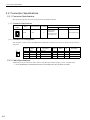
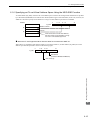
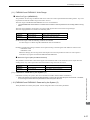
2.3 System Configuration Example
2.3.1 Small-scale Configuration
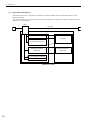
2.3 System Configuration Example
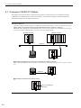
The following shows a system configuration example using the 262IF-01.
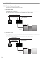
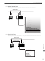
2.3.1 Small-scale Configuration
A network system of several devices can be constructed through the use of one hub.
Hub
Twisted pair cable (STP category 5)
(Maximum cable length: 100 m)
RJ-45 connector
MP2300
MP2200
SVB-01 218IF-02 262IF-01
CPU-02 SVB-01 218IF-02 262IF-01 LIO-04 LIO-04 LIO-04 LIO-01 LIO-01
PLC from other manufacturer
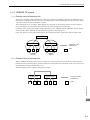
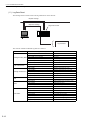
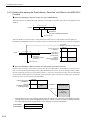
2.3.2 Basic Configuration
A network system of dozens of devices can be constructed by connecting several multi-transceivers and hubs to one
coaxial cable.
Ground terminal
Single-port
transceiver
AUI cable
(Maximum cable length: 50 m)
Multi-port
transceiver
Hub
Overview of 262IF-01 Module
Coaxial cable
(Maximum cable length: 500 m)
Terminator
2
Twisted pair cable (STP category 5)
(Maximum cable length: 100 m)
MP2300
SVB-01 218IF-02 262IF-01
PLC from other manufacturer
PLC from other manufacturer
2-9
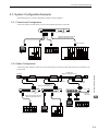
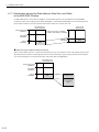
2.3 System Configuration Example
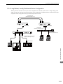
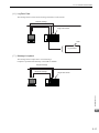
2.3.3 Locally Concentrated Device Configuration
2.3.3 Locally Concentrated Device Configuration
When dozens of devices locally concentrate in a location, a stackable hub can be used to build a network system.
Hub
Stackable hub
PLC from other
manufacturer
MP2300
MP2200
SVB-01 218IF-02 262IF-01
Twisted pair cable
(STP category 5)
(Maximum cable length: 100 m)
2-10
PLC from other
manufacturer
CPU-02 SVB-01 218IF-02 262IF-01 LIO-04 LIO-04 LIO-04 LIO-01 LIO-01
2.3 System Configuration Example
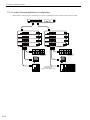
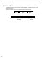
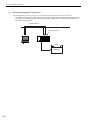
2.3.4 Long Distant, Locally Distributed Device Configuration
2.3.4 Long Distant, Locally Distributed Device Configuration
When a particular controller is far away in a basic configuration of a network system or there is a high-voltage power
supply or noise source near the network, the network can be divided into two segments that are connected with an optical repeater so that a long distant noise-proof network system can be built.
Optical fiber cable
(Maximum cable length: 2 km)
Optical repeater
Optical repeater
Coaxial cable
(Maximum cable length: 500 m)
AUI cable
(Maximum cable length: 50 m)
Hub
Twisted pair cable (STP category 5)
(Maximum cable length: 100 m)
RJ-45 connector
SVB-01 218IF-02 262IF-01
PLC from other manufacturer
Overview of 262IF-01 Module
MP2300
2
2-11
3
Mounting and Starting the Module
This chapter describes how to connect the 262IF-01 Module and start the system, focusing on
262IF-01 Module mounting, communication process setting, and self-configuration.
3.1 Applicable Machine Controllers and Supported Versions - - - - - - - - - - - - -3-2
3.1.1 Applicable Machine Controllers - - - - - - - - - - - - - - - - - - - - - - - - - - - - - - - - - - - - - - - - 3-2
3.1.2 Supported CPU and MPE720 Versions - - - - - - - - - - - - - - - - - - - - - - - - - - - - - - - - - - 3-2
3.2 Mounting and Removing a Module on Machine Controller - - - - - - - - - - - -3-3
3.2.1 Mounting a 262IF-01 Module - - - - - - - - - - - - - - - - - - - - - - - - - - - - - - - - - - - - - - - - - 3-3
3.2.2 Removing a 262IF-01 Module - - - - - - - - - - - - - - - - - - - - - - - - - - - - - - - - - - - - - - - - - 3-6
3.3 Setting the Communication Manager - - - - - - - - - - - - - - - - - - - - - - - - - - -3-8
3.3.1 Opening the Communication Manager - - - - - - - - - - - - - - - - - - - - - - - - - - - - - - - - - - 3-8
3.3.2 Setting the Communication Manager - - - - - - - - - - - - - - - - - - - - - - - - - - - - - - - - - - - - 3-9
3.4.1 Executing Self-configuration - - - - - - - - - - - - - - - - - - - - - - - - - - - - - - - - - - - - - - - - - 3-19
3.5 Starting the MPE720 and Setting Communication or Network Parameters 3-20
3.5.1 Starting MPE720 Ver. 6 and Setting Communication - - - - - - - - - - - - - - - - - - - - - - - - 3-20
3.5.2 Starting MPE720 Ver. 5. and Setting the Network - - - - - - - - - - - - - - - - - - - - - - 3-21
Mounting and Starting the Module
3.4 Self-configuration - - - - - - - - - - - - - - - - - - - - - - - - - - - - - - - - - - - - - - - - 3-19
3
3-1
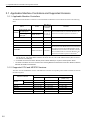
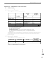
3.1 Applicable Machine Controllers and Supported Versions
3.1.1 Applicable Machine Controllers
3.1 Applicable Machine Controllers and Supported Versions
3.1.1 Applicable Machine Controllers
The MP2000 Series Machine Controllers to which the 262IF-01 Modules can be mounted are listed in the following
table.
Name
Model
Base Unit with 100/
Max. No. of
Connectable
Modules
JEPMC-BU2210
8 modules
when using
the CPU-01
or CPU-02
MP2300
JEPMC-MP2300
2 modules
MP2310
JEPMC-MP2310-E
3 modules
MP2300S
JEPMC-MP2300S-E
1 module
MP2100M
JAPMC-MC2140
8 modules
MP2500MD
JAPMC-MC2540-D
8 modules
MP2200
200-VAC input∗1
Base Unit with 24∗1
VDC input
JEPMC-BU2200
Remarks
The maximum number of connectable Modules is the
total for the maximum expansion to four Racks.∗2
The 262IF-01 Modules can be mounted to Expansion
Racks (which use the MP2200 Base Unit) connected to
an Expansion Interface Board (MP2100MEX, model:
JAPMC-EX2100) mounted to the Machine Controller.
The maximum number of connectable Modules is the
total for the maximum expansion to three Racks.∗2
* 1. A special CPU Module (the CPU-01 or CPU-02) is required.
For the CPU-01, use model JAPMC-CP2200, and for the CPU-02, use model JAPMC-CP2210 (with one slot for
CF card and one USB port).
* 2. An EXIOIF Inter-Rack Connection Module (model: JAPMC-EX2200) is required to add Expansion Racks.
The 262IF-01 Modules cannot be mounted on the following MP2000-series Machine Controllers: MP2100, MP2400,
MP2500, MP2500M, and MP2500D.
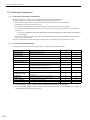
3.1.2 Supported CPU and MPE720 Versions
The CPU versions and MPE720 versions of the Machine Controller corresponding to the 262IF-01 Module are listed in
the following table.
Supported versions
Machine Controller
MP2200
3-2
CPU
MPE720 (CPMC-720)
MPE720 Ver.6
(CPMC-770)
CPU-01
Ver. 2.63 or later
Ver. 5.40 or later
Ver. 6.06 or later
CPU-02
Ver. 2.63 or later
Ver. 5.40 or later
Ver. 6.06 or later
MP2300
Ver. 2.63 or later
Ver. 5.40 or later
Ver. 6.06 or later
MP2310
Ver. 2.63 or later
Ver. 5.40 or later
Ver. 6.06 or later
MP2300S
Ver. 2.63 or later
Ver. 5.40 or later
Ver. 6.06 or later
MP2100M
Ver. 2.63 or later
Ver. 5.40 or later
Ver. 6.06 or later
MP2500MD
Ver. 2.63 or later
Ver. 5.40 or later
Ver. 6.06 or later
3.2 Mounting and Removing a Module on Machine Controller
3.2.1 Mounting a 262IF-01 Module
3.2 Mounting and Removing a Module on Machine Controller
This section describes mounting and removing a 262IF-01 Module.
3.2.1 Mounting a 262IF-01 Module
Use the following procedure to mount a 262IF-01 Module.
When replacing a 262IF-01 Module, first refer to 3.2.2 Removing a 262IF-01 Module on page 3-6 and remove the
262IF-01 Module that needs to be replaced.
( 1 ) Preparation
1.
Backup the Programs.
Save the programs written to the Machine Controller in the personal computer using MPE720.
MPE720 Ver. 5.: Right-click the PLC folder and then select Transfer - All Files - From Controller to
MPE720.
MPE720 Ver. 6.: Open the project file and then select Online - Transfer - Read from Controller.
2.
Save in the Flash Memory.
Using the MPE720, save the program data from the Machine Controller in the flash memory.
MPE720 Ver. 5.: Right-click the PLC folder and then select Transfer - Other - Save to Flash.
MPE720 Ver. 6.: Open the project file and then select Online - Transfer - Save to Flash.
3.
Remove the Machine Controller and Expansion Rack.
Turn OFF the power supply and remove all the cables connected to the Machine Controller or Expansion Rack
(MP2200 Base Unit). Then, remove the Machine Controller and Expansion Rack from the panel or rack, and
place them where there is sufficient space, such as on a work table.
( 2 ) Removing the Option Cover
1.
Remove the Battery Cover.
<MP2200/MP2300/MP2200 Base Unit>
<MP2310/MP2300S>
Insert a hard thin metal object, such as a coin, into
the notch on the side of the battery cover and open
the cover forward to remove the battery cover.
Pull the notch on the side of the MP2300S towards
you to remove the battery cover.
Mounting and Starting the Module
If there is an Option Cover attached to the slot in which the 262IF-0 Module is mounted, remove it using the following
procedure.
3
3-3
3.2 Mounting and Removing a Module on Machine Controller
3.2.1 Mounting a 262IF-01 Module
2.
Remove the Option Cover.
Hold the battery cover with the front facing forward, insert the protrusion on the battery cover into the notch at
the top of the Option Cover, and release the hook on the Option Cover.
Release the hook on the bottom in the same way and remove the Option Cover.
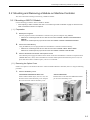
( 3 ) Mounting the 262IF-01 Module
1.
Insert the 262IF-01 Module.
Hold onto the top and bottom of the 262IF-01 Module, align the Module with the left side of the guide rail inside
the option slot, and insert the Module straight in.
* If the Module is not inserted on the guide rail, the FG bar on the bottom of the slot may be damaged.
Guide
rail
2.
Connect to the Mounting Base Connector.
After inserting the Module all the way to the back, press the Module firmly until it connects securely to the
Mounting Base connected. If the Module is connected securely, the front of the Module should approximately
align with the hooks.
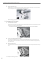
3.
Mount the Option Panel.
Insert the hole on the bottom of the option panel into the bottom hook and then securely attach the hole to the top
hook.
This completes the mounting procedure.
3-4
3.2 Mounting and Removing a Module on Machine Controller
3.2.1 Mounting a 262IF-01 Module
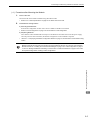
( 4 ) Procedure after Mounting the Module
1.
Connect the Hub.
Connect the hub to the 262IF-01 Module using the Ethernet cable.
Refer to 2.2.2 Cable Specifications on page 2-8 for cables that can be used.
Create Module Configurations.
a) Mounting New Modules
Execute self-configuration for each slot in which a 262IF-01 Module was mounted.
Refer to 3.4 Self-configuration on page 3-19 for information on self-configuration.
b) Replacing Modules
Turn OFF the CNFG and INIT DIP switch pins on the Machine Controller and turn ON the power supply.
Once the power has been turned ON, the module configuration can be modified as required.
Refer to 4.1.1 Displaying the Module Configuration Window on page 4-2 for information on the Module configuration.
A Communication Module other than the 262IF-01 Module is required for communication between the
Machine Controller and the personal computer running the MPE720. Be sure to mount the Communication
Module and refer to 3.3 Setting the Communication Manager on page 3-8, 3.4 Self-configuration on page 319, and 3.5 Starting the MPE720 and Setting Communication or Network Parameters on page 3-20 to make
the required settings before creating module configurations.
Mounting and Starting the Module
2.
3
3-5
3.2 Mounting and Removing a Module on Machine Controller
3.2.2 Removing a 262IF-01 Module
3.2.2 Removing a 262IF-01 Module
Use the following procedure to remove a 262IF-01 Module.
( 1 ) Preparation
1.
Backup the Programs.
Save the programs written to the Machine Controller in the personal computer using MPE720.
MPE720 Ver. 5.: Right-click the PLC folder and then select Transfer - All Files - From Controller to
MPE720.
MPE720 Ver. 6.: Open the project file and then select Online - Transfer - Read from Controller.
2.
Remove the Machine Controller and Expansion Rack.
Turn OFF the power supply and remove all the cables connected to the Machine Controller or Expansion Rack.
Then, remove the Machine Controller and Expansion Rack from the panel or rack, and place them where there is
sufficient space, such as on a work table.
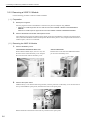
( 2 ) Removing the 262IF-01 Module
1.
2.
Remove the Battery Cover.
<MP2200/MP2300/MP2200 Base Unit>
<MP2310/MP2300S>
Insert a hard thin metal object, such as a coin, into
the notch on the side of the battery cover and open
the cover forward to remove the battery cover.
Pull the notch on the side of the MP2300S towards
you to remove the battery cover.
Remove the Option Panel.
Hold the battery cover with the front facing forward, insert the protrusion on the battery cover into the notch at
the top of the Module's option panel, and release the hook on the option panel.
Release the hook on the bottom in the same way and remove the option panel.
3-6
3.2 Mounting and Removing a Module on Machine Controller
3.2.2 Removing a 262IF-01 Module
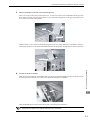
3.
Remove the 262IF-01 Module from the Mounting Base.
Pull out on the top of the option panel and remove it. A notch can be seen in the I/O Module from the gap in the
panel. Insert the round projection on the battery cover (see the following figure) into the gap in the panel so that
it is inserted in the notch in the Module.
Notch
Projection
Hold the battery cover as shown in the following figure and use it to gently pull back on the Module, rotating it
indicated by the arrows, to disconnect the Module from the Mounting Base. The Module will move towards you.
4.
Pull Out the 262IF-01 Module.
Hold onto the top and bottom of the Module with your fingers and pull the Module straight out. Be sure to hold
onto the edges of the Module. Do not touch the components mounted to the Module.
Mounting and Starting the Module
Fulcrum
3
Place the Module that you removed into the bag that it was delivered in and store it.
Always attach an Option Cover (JEPMC-OP2300) to any unused slot.
3-7
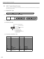
3.3 Setting the Communication Manager
3.3.1 Opening the Communication Manager
3.3 Setting the Communication Manager
This section describes the software called the Communication Manager that is used to set the communication method
for engineering communication between the personal computer running the MPE720 and the MP2000 Series Machine
Controller.
Use a Communication Module other than the 262IF-01 Module for communication between the Machine Controller
and the personal computer running the MPE720 and set an appropriate communication method depending on the Module used.
Set the communication conditions with the Communication Manager after the MPE720 Programming Device has been
installed. Once they have been set, it is unnecessary to set from the next startup except when other conditions are to be
added.
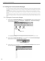
3.3.1 Opening the Communication Manager
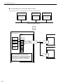
1.
Double-click the Communication Manager Icon in the YE_Applications Folder to start the Communication Manager. Alternatively, select All Programs - YE-Applications - Communication Manager
under the Windows Start Button.
Double-click
The Communication Manager Icon will be displayed in the task tray at the right bottom of the window.
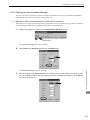
2.
Double-click the Communication Manager Icon in the task tray and the Communication Manager
Window like the one shown in the step 3 will be displayed.
Communication Manager Icon
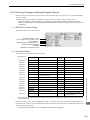
3.
3-8
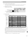
Logical ports for up to 16 channels can be set in the Communication Manager Window. Select and
set unused logical ports from the top.
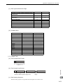
3.3 Setting the Communication Manager
3.3.2 Setting the Communication Manager
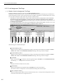
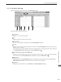
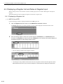
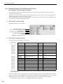
3.3.2 Setting the Communication Manager
This section describes the procedure to set the Communication Manager for connecting the MPE720 and MP2000
Series Machine Controller for each type of communication port.
( 1 ) Settings for Serial Communication Port (RS-232C Connection)
These settings are required to perform engineering communication via the serial (RS-232C) port of each Communication Module using the MPE720. Use the following procedure to make the settings.
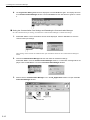
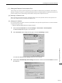
1.
Double-click Logical PT number 1 in the Communication Manager Window.
Double-click
The Logical Port Setting Dialog Box will appear.
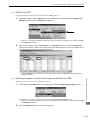
Select Serial under Port Kind and then click the Detail Button.
The Serial Port Setting Dialog Box will appear.
3.
Match the settings under Physical Port to the computer's serial communication port. Leave the other
items on the default settings. Once the settings have been completed and checked, click the OK Button to close the dialog box.
Mounting and Starting the Module
2.
3
3-9
3.3 Setting the Communication Manager
3.3.2 Setting the Communication Manager
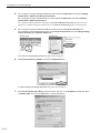
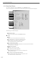
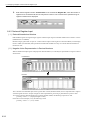
4.
The Logical Port Setting Window will be displayed. Click the OK Button again. The display will return
to the Communication Manager Window. Check that Serial has been allocated to Logical PT number
1.
Saving the Communication Port Settings and Restarting the Communication Manager
Save the communication port settings, and restart the Communication Manager to validate the settings.
1.
Select File - Save. A save confirmation window will be displayed. Click the Yes Button to save the
communication port settings.
These settings will be used as the communication port information whenever the Communication Manager is
started.
2.
Close the Communication Manager Window and restart to validate the settings.
Select File - Exit to close the Communication Manager Window. A confirmation message will be displayed. Click the Yes Button to close the Communication Manager Window.
3.
Double-click the Communication Manager Icon in the YE_Applications Folder to reopen the Communication Manager Window.
Double-click
3-10
3.3 Setting the Communication Manager
3.3.2 Setting the Communication Manager
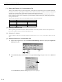
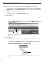
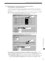
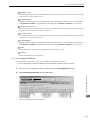
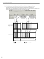
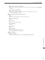
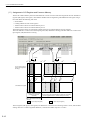
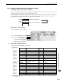
( 2 ) Setting the Ethernet Communication Port
These settings are required to perform engineering via the 10Base-T communication port (Ethernet) of the 218IF-01
Module. For Ethernet connection, a general-purpose Ethernet board or PCMCIA Ethernet card must be mounted on the
personal computer. Prior to make settings, the IP address of the personal computer must be set.
[ a ] Mounting an Ethernet Card
Mount a general-purpose Ethernet board or PCMCIA Ethernet card on the specified connector of the personal computer. Also, install the driver provided with the Ethernet card.
[ b ] Setting the IP Address
Prior to make settings for Ethernet connection, the IP address of the personal computer must be set. Set the IP address
using the following procedure.
Make the following settings with the LAN cable connected.
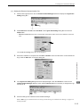
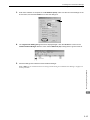
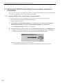
1.
Click the Windows Start Button and select Settings - Control Panel - Internet Options.
The Internet Properties Dialog Box will be displayed.
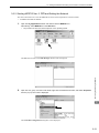
Click Connections Tab to display the tab page. Click the LAN Settings... Button.
The Local Area Network (LAN) Settings Dialog Box will be displayed.
3.
Check that the Automatically detect settings Check Box is cleared, and click the OK Button to close
the dialog box.
Mounting and Starting the Module
2.
3
3-11
3.3 Setting the Communication Manager
3.3.2 Setting the Communication Manager
4.
For a computer running the Windows 2000 OS, click the Windows Start Button and select Settings Control Panel - Network and Dial-up Connections.
For a computer running the Windows XP OS, click the Windows Start Button and select Settings Control Panel - Network Connections.
On a computer running the Windows 2000 OS, the Network and Dial-up Connections Window will be displayed. On a computer running the Windows XP OS, the Network Connections Window will be displayed.
5.
On a computer running the Windows 2000 OS, double-click the Local Area Connection Icon.
On a computer running the Windows XP OS, click Local Area Connection and click Change settings
of this connection in the Network Tasks Field.
Windows 2000 Windows XP
The Local Area Connection Properties Dialog Box will be displayed.
6.
Select Internet Protocol (TCP/IP) and click the Properties Button.
The Internet Protocol (TCP/IP) Properties Dialog Box will be displayed.
7.
3-12
Click Use the following IP address Option and enter 192 168 1 2 for IP address and 255 255 255 0
for Subnet mask. Then click the OK Button to close the dialog box.
3.3 Setting the Communication Manager
3.3.2 Setting the Communication Manager
[ c ] Setting the Ethernet Communication Port
1.
Double-click Logical Port No. 2 in the Communication Manager Window to display the Logical Port
Setting Dialog Box.
2.
Select Ethernet or CP-218 under Port Kind in the Logical Port Setting Dialog Box and click the
Detail Button.
Ethernet and CP-218 set the same communication specifications. Either can be set for Ethernet communications.
The CP-218 Port Setting Dialog Box will be displayed.
Enter the IP address of computer and click OFF for Default. Leave the other items on their default settings. Click the OK Button to close the dialog box.
4.
The Logical Port Setting Dialog Box will be displayed again. Click the OK Button to return to the
Communication Manager Window. Check that the CP-218 (Ethernet connection) is assigned to Logical Port No. 2.
5.
Save the settings and restart the Communication Manager.
Mounting and Starting the Module
3.
3
Refer to Saving the Communication Port Settings and Restarting the Communication Manager on page 3-10
for the procedure.
3-13
3.3 Setting the Communication Manager
3.3.2 Setting the Communication Manager
( 3 ) Setting the Ethernet (LP) Communication Port
These are the optimum settings to perform engineering via the Ethernet communication port of the 218IF-02 Module.
For Ethernet connection, a general-purpose Ethernet board or PCMCIA Ethernet card must be mounted on the personal
computer. Prior to make settings, the IP address of the personal computer must be set.
The Ethernet (LP) communication port can be connected to the 218IFB function of the 218IF-02 Module. It has a
larger engineering message size in comparison to previous Ethernet communication ports, enabling high-speed engineering communication.
The port type and Modules that can be used together are given in the following table.
Port Type
Module
CP-218
218IF-01(218IF)
{
218IF-02(218IFB)
{
Ethernet
{
{
Ethernet (LP)
×
{
[ a ] Mounting an Ethernet Card
Mount a general-purpose Ethernet board or PCMCIA Ethernet card on the specified connector of the personal computer. Also, install the driver provided with the Ethernet card.
[ b ] Setting the IP Address
Set the IP address of the person computer using the procedure given in 3.3.2 ( 2 ) [ b ] Setting the IP Address on page
3-11.
[ c ] Setting the Ethernet (LP) Communication Port
1.
Double-click Logical Port No. 3 in the Communication Manager Window to display the Logical Port
Setting Dialog Box.
2.
Select Ethernet (LP) under Port Kind in the Logical Port Setting Dialog Box and click the Detail Button.
The CP-218/Ethernet (LP) Port Setting Dialog Box will be displayed.
3-14
3.3 Setting the Communication Manager
3.3.2 Setting the Communication Manager
3.
Enter the IP address of computer for the IP Address (First), make sure the rest of the settings are as
shown below, and click the OK Button to close the dialog box.
4.
The Logical Port Setting Dialog Box will be displayed again. Click the OK Button to return to the
Communication Manager Window. Check that the Ethernet (LP) is assigned to Logical Port No. 3.
5.
Save the settings and restart the Communication Manager.
Mounting and Starting the Module
Refer to Saving the Communication Port Settings and Restarting the Communication Manager on page 3-10
for the procedure.
3
3-15
3.3 Setting the Communication Manager
3.3.2 Setting the Communication Manager
( 4 ) Setting the CP-215 Communication Port
These settings are required to perform engineering communication via the CP-215 communication port of the 215AIF01 Module using the MPE720.
A CP-215PC/AT card must be mounted on the personal computer and set for the CP-215 connection. Contact your
Yaskawa representative for more information.
[ a ] Setting the CP-215 Communication Port
1.
Double-click Logical Port No. 4 in the Communication Manager Window.
The Logical Port Setting Dialog Box will be displayed.
2.
Select CP-215 under Port Kind in the Logical Port Setting Dialog Box and click the Detail Button.
The CP-215 Port Setting Dialog Box will be displayed.
3-16
3.
The Hardware Tab Page will be displayed. Select the type of CP-215PC/AT card mounted on the personal computer under CP-215 Type.
4.
Set the I/O port number of the mounted CP-215PC/AT card under Physical No. Set the I/O port number to 1 when using one CP-215PC/AT card. When using two or more cards, allocate ports 2, 3, and 4
sequentially.
3.3 Setting the Communication Manager
3.3.2 Setting the Communication Manager
5.
Click the Parameter Tab in the CP-215 Port Setting Dialog Box. Set the following items.
Local Station Address
: Set the MPE720 (personal computer) station number to between 1 and 64.
Local Network Address : Set the number of the network to which the MPE720 (personal computer) is connected to
between 1 and 254. If there is only one network segment, set 1.
Max Connect Station
: Set the number of CP-215 network stations.
Token Round Time
Setting
: This is the target time from when each station receives the token until the next time the same
station receives the token. Set 100.
MEMOBUS Response : This is the time from when a message is sent until the response is received. Set 255.
Watch Time
Leave the other items set to their default values.
Click the Channel Tab in the CP-215 Port Setting Dialog Box. Select 2 under Panel Command
Channel. Leave the other items set to their default values and click the OK Button to close the dialog
box.
Mounting and Starting the Module
6.
3
3-17
3.3 Setting the Communication Manager
3.3.2 Setting the Communication Manager
7.
The Logical Port Setting Dialog Box will be displayed again. Click the OK Button to return to the
Communication Manager Window. Check that CP-215 (MPLINK/CP-215 connection) is assigned to
the Logical Port No. 4.
8.
Save the settings and restart the Communication Manager.
Refer to Saving the Communication Port Settings and Restarting the Communication Manager on page 3-10
for the procedure.
3-18
3.4 Self-configuration
3.4.1 Executing Self-configuration
3.4 Self-configuration
The self-configuration function automatically detects the Option Modules connected to the Machine Controller and
automatically generates the files for the Module configuration definitions and the detailed definition of each Module.
Executing self-configuration will greatly reduce the system startup procedure.
After executing self-configuration, always save data to flash memory so that the results of self-configuration
are saved in the Machine Controller.
3.4.1 Executing Self-configuration
The methods used to execute self-configuration are described below.
( 1 ) Setting the CNFG DIP Switch Pin and Cycling Power (MP2200/MP2300/MP2310/
MP2300S)
Self-configuration can be executed by turning ON the CNFG DIP switch pin on the Machine Controller and turning the
power OFF and then ON again. The result will depend on the setting of the INIT DIP switch pin.
CNFG
INIT
Result
ON
ON
• The Module configuration definitions are updated.
• The default allocations are made for all of the Modules that are detected.
ON
OFF
• The Module configuration definitions are updated.
• The definitions for any Modules for which there are already definitions are not changed.
• The default values are allocated in the definitions for any new Modules that are detected.
The DIP switch is not normally used for the MP2100M/MP2500MD. For these Machine Controllers, use the MPE720
as described next.
Start the MPE720, start the Engineering Manager, and then select Order - Self Configure All Modules from the Main
Menu. Alternatively, select the Module for which self-configuration is to be executed in the Module Configuration
Window, and then select Order - Module Self-configuration from the Main Menu.
Refer to 4.1.1 Displaying the Module Configuration Window on page 4-2 for the procedure to display the Module
Configuration Window.
The result depends on the command that is used, as described below.
Command
Result
Self-configuration for
all Modules
• The Module configuration definitions are updated.
• The definitions for any Modules for which there are already definitions are not changed.
• The default values are allocated in the definitions for any new Modules that are detected.
Module Self-configuration
• Definitions are allocated only for the selected Module.
• The definitions for any Modules for which there are already definitions are not changed.
• The default values are allocated in the definitions for any new Modules that are detected.
Mounting and Starting the Module
( 2 ) Using the MPE720 (MP2100M/MP2500MD)
3
3-19
3.5 Starting the MPE720 and Setting Communication or Network Parameters
3.5.1 Starting MPE720 Ver. 6 and Setting Communication
3.5 Starting the MPE720 and Setting Communication or Network
Parameters
This section describes how to start the MPE720 and set the communication parameters in the project file (MPE720 Ver.
6) or the network parameters in the PLC folder (MPE720 Ver.5.).
3.5.1 Starting MPE720 Ver. 6 and Setting Communication
This section describes how to start the MPE720 and set the communication parameters in the object file.
Disconnect the Machine Controller when setting the parameters.
Create the object file in advance.
1.
Select Online - Communications Setting from the Main Menu. Alternatively, select Controller Communications Setting (or Project - Communications Setting) in the Start Window.
The Communications Setting Dialog Box will be displayed.
2.
Select the logical port number to use to connect the Machine Controller and click the Setting Button.
Settings for the logical port numbers are made with the Communication Manager. Refer to 3.3 Setting the
Communication Manager on page 3-8 for the Communication Manager setting procedure.
Communication will be set and the dialog box will close.
3-20
The Connection and Setting Buttons will be disabled while the Machine Controller is connected.
3.5 Starting the MPE720 and Setting Communication or Network Parameters
3.5.2 Starting MPE720 Ver. 5. and Setting the Network
3.5.2 Starting MPE720 Ver. 5. and Setting the Network
This section describes how to start the MPE720 and set the network parameters in the PLC folder.
Create the PLC folder in advance.
1.
Open the YE_Applications Folder and double-click the MPE720 Icon.
Alternatively, select MPE720 from the Start Menu.
The procedure to select the network depends on the operating system.
2.
Open the root, group, and then order folder, right-click the desired PLC folder, and select Properties
from the pop-up menu that is displayed.
Mounting and Starting the Module
The MPE720 will start and the File Manager Window will be displayed.
3
The Controller Configuration Dialog Box will be displayed.
3-21
3.5 Starting the MPE720 and Setting Communication or Network Parameters
3.5.2 Starting MPE720 Ver. 5. and Setting the Network
3.
Click the Network Tab and select Yes for OnLine.
Fields will be displayed for the logical port number, unit number, and route so that they can be set.
4.
For Logical Port No. (Device Type), set the logical port number to use from the logical port numbers
that were set with the Communication Manager.
The contents display on the tab page may change depending on the port that is selected.
The devices types indicate the following connections: CP-217 indicates an RS-232C connection (serial port),
CP-218 indicates an Ethernet connection, and CP-215 indicates a connection through a CP-215PC/AT card
mounted on the personal computer.
5.
3-22
<RS-232C Connection>
Leave all other settings on their default values and click the OK Button.
3.5 Starting the MPE720 and Setting Communication or Network Parameters
3.5.2 Starting MPE720 Ver. 5. and Setting the Network
<Ethernet Connection>
Enter the IP address of the personal computer and click the OK Button.
<CP-215 Connection>
Enter the network number and station number and click the OK Button.
6.
A confirmation dialog box will be displayed. Click the Yes Button. This completes selecting the logical
port.
These transmission definition settings are required for each Communication Module. Refer to Machine Controller
MP2000 Series Communication Module User’s Manual (Manual No.: SIEPC88070004) for details on the transmission
definition settings.
Mounting and Starting the Module
Enter the same network number and station number as the ones set with the Communication Manager.
3
3-23
4
FL-net Transmission Definition
For 262IF-01 FL-net communication using a MP2000 Series Machine Controller, an FL-net
transmission definition file must be created. This chapter discusses how to make an FL-net
transmission definition on the MPE720 screen.
4.1 Displaying the FL-net Transmission Configuration Window - - - - - - - - - - - -4-2
4.1.1 Displaying the Module Configuration Window - - - - - - - - - - - - - - - - - - - - - - - - - - - - - - 4-2
4.1.2 Displaying the FL-net Transmission Configuration Window from the Module
Configuration Window - - - - - - - - - - - - - - - - - - - - - - - - - - - - - - - - - - - - - - - - - - - - - - 4-3
4.2 FL-net Transmission Definition - - - - - - - - - - - - - - - - - - - - - - - - - - - - - - - -4-4
4.2.1 Transmission Parameters Tab Page - - - - - - - - - - - - - - - - - - - - - - - - - - - - - - - - - - - - 4-4
4.2.2 Link Assignment Tab Page - - - - - - - - - - - - - - - - - - - - - - - - - - - - - - - - - - - - - - - - - - - 4-6
4.2.3 Link Status Tab Page - - - - - - - - - - - - - - - - - - - - - - - - - - - - - - - - - - - - - - - - - - - - - - - 4-9
4.2.4 Status Detail Window - - - - - - - - - - - - - - - - - - - - - - - - - - - - - - - - - - - - - - - - - - - - - - 4-10
4.2.5 Status Tab Page - - - - - - - - - - - - - - - - - - - - - - - - - - - - - - - - - - - - - - - - - - - - - - - - - 4-12
4.2.6 Network Configuration Window - - - - - - - - - - - - - - - - - - - - - - - - - - - - - - - - - - - - - - - 4-13
FL-net Transmission Definition
4.2.7 Saving FL-net Transmission Definitions - - - - - - - - - - - - - - - - - - - - - - - - - - - - - - - - - 4-14
4
4-1
4.1 Displaying the FL-net Transmission Configuration Window
4.1.1 Displaying the Module Configuration Window
4.1 Displaying the FL-net Transmission Configuration Window
This section describes how to open the Module Configuration Window from the MPE720, open the Transmission
Configuration Window from the Module Configuration Window, and set the transmission definitions for the FL-net
Module.
4.1.1 Displaying the Module Configuration Window
Use the following procedure to display the Module Configuration Window.
( 1 ) MPE720 Ver. 6
1.
Start the MPE720 on the personal computer connected to the Machine Controller and open the project
file.
For information on starting the MPE720, refer to Machine Controller MPE720 Programming Device Ver. 6 User's
Manual (Manual No.: SIEPC88070030).
2.
Select Setup - Module configuration in the Launcher, or double-click the Module configuration Icon
in the system subprogram.
The Engineering Manager will be started and the Module Configuration Window will be displayed (see next
page).
( 2 ) MPE720 Ver. 5
1.
Start the MPE720 on the personal computer connected to the Machine Controller and use the File Manager to log in and go online with the application for the Machine Controller.
For information on starting the MPE720 and logging on, refer to MPE720 Software for Programming Device
User's Manual (Manual No.: SIEPC88070005).
2.
Double-click the Module Configuration Icon in the Definition Folder.
The Engineering Manager will be started and the Module Configuration Window will be displayed (see next
page).
4-2
4.1 Displaying the FL-net Transmission Configuration Window
4.1.2 Displaying the FL-net Transmission Configuration Window from the Module Configuration Window
4.1.2 Displaying the FL-net Transmission Configuration Window
from the Module Configuration Window
As the result of executing self-configuration, all Option Modules connected to the Machine Controller will be displayed in the Controller Area of the Module Configuration Window. (Refer to 3.4.1 Executing Self-configuration on
page 3-19.)
In the Controller Area, select the 262IF-01 cell, and then double-click the slot number cell for FL-net in the Module
Details Area. The FL-net Transmission Configuration Window (see next page) will be displayed.
<MP2300/MP2310/MP2300S Module Configuration Window>
1
2
Click.
Double-click.
1
2
Click.
Double-click.
FL-net Transmission Definition
<MP2100M/MP2200/MP2500MD Module Configuration Window>
4
In Online Mode, the FL-net transmission definitions data saved in the Machine Controller are displayed. In Offline
Mode, the definitions data saved in the personal computer on which MPE720 is running is displayed.
The FL-net Transmission Configuration Window is composed of four tab pages: Transmission Parameters, Link
Assignment, Link Status, and Status. These tab pages are used to set the definitions and monitor the settings.
If the Transmission Configuration Window is being opened for the first time, a “new file” message box will be displayed and the FL-net Transmission Configuration Window will be displayed when the OK Button is clicked.
4-3
4.2 FL-net Transmission Definition
4.2.1 Transmission Parameters Tab Page
4.2 FL-net Transmission Definition
4.2.1 Transmission Parameters Tab Page
Set the parameters required for FL-net communication. The following gives a detailed description.
Configuration
information
1
2
3
4
5
6
Configuration Information
The 262IF-01 configuration information is displayed. This configuration information is the same as the information
displayed in the Module Details Area in the Module Configuration Window.
RACK#: The rack number of the rack in which the 262IF-01 is defined.
Slot#: The slot number of the slot in which the 262IF-01 is defined.
CIR#: The circuit number of the Ethernet port on the 262IF-01.
When the MSG-SND or MSG-RCV function is used, set the circuit number displayed here for CIR# (circuit
number).
Setting the Transmission Parameters
1
IP Address
Set the IP address of the local node. The last digit is used as a module node number.
There are four 8-bit fields delimited by periods (.). Input a decimal number for each field.
Field No. 4: Module node numbers 1 to 254
Field No. 3: 0 to 255
Field No. 2: 0 to 255
Field No. 1: 192 to 223
Do not use the same address as another node. If a duplicate IP address is entered, undetect will be selected
as Bit 7 Address overlapping detection in the Status Detail Window (refer to page 4-10), resulting in a disabled network connection.
2
Subnet Mask
Set the subnet mask for the IP address of the local node.
Since “255.255.255.0” is automatically set in FL-net, use this default value.
3
Token monitoring time
Set the monitoring time in units of ms from when the node acquires the token until the node issues a token.
This time can be set in a range from 1 to 255 (ms).
4
Minimum permissible frame interval
Set the time in units of 100 μs from when the local node receives a token from a remote node until the local node
sends a frame.
This time can be set in a range from 0 to 50 (0-5 ms).
4-4
4.2 FL-net Transmission Definition
4.2.1 Transmission Parameters Tab Page
5
Common memory area 1 size
Make this setting to assign registers to respective areas 1 and 2 in the entire common memory within an I/O
register range assigned in the Module Configuration Window. The 1 size of common memory area beginning
with an I/O leading register number is assigned for area 1, and the remaining range (from [I/O leading register
number + 1 size of common memory area] to I/O ending register number) is assigned for area 2.
Set the size in units of words within a range from 0 to 200H (0 to 512 words).
The maximum value of the area 1 size is 200H and that of the area 2 size is 2000H.
The default value is 200(H). When reducing this value, reduce the I/O register range in advance on the Module
Configuration Window by the value to be reduced (or by the value greater than the value to be
reduced).When an attempt is made to reduce a common memory area 1 range without this operation, an error
will occur.
<Example>
To set common memory area 1 size to 100(H) when an I/O leading register number is 0402 and an I/O ending
register number is 2601, the I/O register number must be reduced to 2501 or less or the I/O leading register
number must be set to 0302 or more.
When the default value is changed, an error occurs for the following reasons.
Because the common memory area 1 size is 200H and the I/O register size is 2200H by default, the default
common memory area 2 size (I/O register size - common memory area 1 size) is 2000H (maximum value of
common memory area 2 size). When the common memory area 1 size is less than the default value of 200, an
error will occur because the common memory area 2 size exceeds the maximum value of 2000H.
For common memory and areas 1 and 2, refer to 5.3.1 ( 4 ) Common Memory and Areas 1 and 2 on page 5-9
and 5.3.1 ( 5 ) Assignment of I/O Register and Common Memory on page 5-10.
For relationship between common memory assigned to the I/O register and common memory assigned to each
node, refer to 4.2.2 ( 3 ) Link Assignment Setting Example and Common Memory Assignment Image on page
4-8.
6
Node name
Enter a name of the local node up to ten characters.
Terminology: Minimum Permissible Frame Interval
FL-net Transmission Definition
FL-net shares this minimum permissible frame interval in the network. Each node calculates and updates the maximum value of
minimum permissible frame intervals set by nodes joined to the network each time a node joins or leaves the network.
4
4-5
4.2 FL-net Transmission Definition
4.2.2 Link Assignment Tab Page
4.2.2 Link Assignment Tab Page
( 1 ) Details of the Link Assignment Tab Page
Set link assignment for each node in FL-net on the Link Assignment Tab Page.
Information on common memory areas 1 and 2 of each node, which has been received through cyclic transmission, is
stored in the registers of areas 1 and 2 of each node set here. In addition, information on common memory areas 1and 2
of a local node is broadcast to other nodes on FL-net when it holds the token.
Information on common memory areas 1 and 2 of other nodes, which is to be assigned here, must be identical to
that assigned to the nodes for themselves. To assign other nodes, assignment information must be obtained in
advance or the Network Configuration Window (refer to page 4-13) must be opened with the node joined to FL-net
to confirm the node information.
For the relationship between common memory area assignments to nodes and I/O registers, refer to 4.2.2 ( 3 ) Link
Assignment Setting Example and Common Memory Assignment Image on page 4-8.
1
2
3
4
5
6
7
8
9
10
11
12
13
The following gives a detailed description.
1
Common Memory Area 1
Displays the area 1 address range determined according to the setting of the transmission parameter Common
memory area 1 size on the Transmission Parameters Tab Page. This range cannot be changed.
2
Common Memory Area 2
Displays the area 2 address range determined according to the setting of the transmission parameter Common
memory area 1 size on the Transmission Parameters Tab Page. This range cannot be changed.
3
Local Node
When a node number ( 5 ) is identical to the least significant digit in IP address on the Transmission Parameters Tab Page, “**” is displayed here to indicate a local node.
4
No.
Displays the interface number for CPU (fixed).
5
Node Number
Enter the node number (least significant digit in IP address) of a node to be assigned.
This value can be set in a range from 1 to 254. Note that the setting value must be unique.
6
Area 1 Common memory
Set the I/O leading register address of FL-net common memory area 1 of a target node for assignment in units of
words. This value can be set in a range from 0 to 511.
4-6
4.2 FL-net Transmission Definition
4.2.2 Link Assignment Tab Page
Size (area 1 size)
7
Set the assignment size of FL-net common memory area 1 of a target node for assignment in units of words. This
value can be set in a range from 0 to 512.
I/O area REG-No
8
Displays the address range of corresponding I/O registers according to the common memory area 1 assignment.
“OW( to )” is displayed for the local node and “IW( to )” for other nodes.
Area 2 Common memory
9
Set the I/O leading register address of FL-net common memory area 2 of a target node for assignment in units of
words. This value can be set in a range from 0 to 8191.
10
Size (area 2 size)
Set the assignment size of FL-net common memory area 2 of a target node for assignment in units of words. This
value can be set in a range from 0 to 8192.
11
I/O area REG-No
Displays the address range of corresponding I/O registers according to the common memory area 2 assignment.
“OW( to )” is displayed for the local node and “IW( to )” for other nodes.
12
SCAN
Set the refresh cycle of the I/O area assigned for each node to “High” or “Low.”
13
Comment
Enter each node name up to ten characters.
( 2 ) Link Assignment Deletion
Link assignments can be deleted in units of lines according to the following procedure.
Care should be taken for assignment deletion because the deleted assignment cannot be restored.
Click any cell on an assignment line to be deleted from the Link Assignment Tab Page.
2.
Select Edit-Assignment Delete from the Main Menu.
FL-net Transmission Definition
1.
4
The selected assignment line will be deleted.
4-7
4.2 FL-net Transmission Definition
4.2.2 Link Assignment Tab Page
( 3 ) Link Assignment Setting Example and Common Memory Assignment Image
The following figure shows a link assignment example and a common memory assignment image.
Because areas 1 and 2 in the local node are used only for sending, they work as output registers (OW). Because areas 1
and 2 in other nodes are used only for reception, they work as input registers (IW).
Common memory area 1 size
(variable in a range from
0 to 200H)
91
FF
IW
31
64
12
IW
Common memory area 2 size (variable in a range from 0 to 2200H)
(I/O ending register number − common memory area 1 size)
Set by Transmission Parameters
Tab Page
㧦Local node (OW register)
4-8
81
00
Node number 4 (input)
46
12
Node number 4 (input)
Node number 2 (output)
Node number 1 (input)
O
IW
W
12
12
00
3C
Area 2
IW
I
Node number 4 (input) W 1
IW 00A
10
0C
10
W
O
Node number 2 (output)
Node number 1 (input)
IW
10
00
04
Area 1
CPU Module I/O register
01
70
00
Node number 1 (input)
Node number 2 (output)
00
60
00
00
11
05
1
00 0
12
10 words
Node number 4 (input)
00
04
Node number 2 (output)
Node number 1 (input)
FL-net common memory
(Set by Link Assignment
Tab Page)
00
00
00
6 words
㧦Other node (IW register)
4.2 FL-net Transmission Definition
4.2.3 Link Status Tab Page
4.2.3 Link Status Tab Page
The FL-net link status can be monitored on the Link Status Tab Page.
1
2
3
4
5
6
The following gives a detailed description.
1
Local Node
Displays “**” as a local node number.
2
No.
Dispalys the Interface number for CPU (fixed).
3
Node Number
Dispalys the node number of each node set in the Link Assignment Tab Page.
4
FA link
Displays the current status regarding whether each node set in the Link Assignment Tab Page has joined or left
FL-net as “Join” or “Leave.”
This information is bit 0 link information of the FL-net link information. The other information can be referenced
5
6
).
High-ranking layer (Upper layer RUN/STOP)
Displays the bit 7 RUN/STOP status of the FL-net upper layer status as “RUN” or “Stop.” The other information
can be referenced on the Status Detail Window displayed by clicking the Detail Button (
6
6
).
Detail Button
Click this button, and the Status Detail Window will be displayed to show information such as FA Link and
High-ranking layer status of a selected node with a code as a bitwise explanation.
7
Comment
FL-net Transmission Definition
on the Status Detail Window displayed by clicking the Detail Button (
Displays each node comment set in the Comment of the Link Assignment Tab Page.
4
4-9
4.2 FL-net Transmission Definition
4.2.4 Status Detail Window
4.2.4 Status Detail Window
This window is displayed by clicking the Detail Button on the Link Status Tab Page.
The FL-net link information, upper layer status, and token monitoring time of the selected node are displayed.
1
2
3
4
5
6
7
8
9
10
11
12
13
14
15
16
17
The following gives a detailed description.
1
Node (Node number)
Displays a node number selected on the Link Status Tab Page.
FA Link
2
Status
Displays a status code of the link status of the selected node.
3
Bit 0: Node status on in-ring/out-ring (Joined/not joined)
Displays whether a selected node has joined or left FL-net.
ON = In-ring (joined), OFF = Out-ring (not joined)
4
Bit 1: Communication invalidity
Displays whether the communication disabled status of a selected node has been detected.
ON = Detected, OFF = Not detected
5 • 6
Bits 2 and 3: Reserve
Reserved by system. Always set to OFF.
7
Bit 4: Upper layer operation signal error
Displays whether there is an operation signal error in the upper layer.
ON = Error, OFF = Normal
8
Bit 5: Common memory data validity notification
Displays whether common memory data in the selected node is valid.
ON = Enable (valid), OFF = Disable (invalid)
4-10
4.2 FL-net Transmission Definition
4.2.4 Status Detail Window
Bit 6: Common memory setting completion
9
Displays whether the settings for common memory areas 1 and 2 have been completed on the Link Assignment
Tab Page.
ON = Complete, OFF = Incomplete
10
Bit 7: Address overlapping detection
Displays whether duplication of the I/O area address in the common memory has been detected.
ON = Detect (duplicate), OFF = Undetect
High-ranking Layer Status (Status of upper layer)
11
Status
Displays a status code of the upper layer status of the selected node.
12
Bit 0 to B: U_ERR_CODE
Not used.
13
Bit C: Reserve
Reserved by system. Always set to OFF.
14
Bit D: WARNING
Not used.
15
Bit E: ALARM
Not used.
16
Bit F: RUN/STOP
Displays an operating status of the upper layer.
ON = RUN (operating), OFF = STOP (stopped)
Network Information
17
Token monitoring time
Displays the network monitoring time set on the Transmission Parameter Tab Page.
FL-net Transmission Definition
4
4-11
4.2 FL-net Transmission Definition
4.2.5 Status Tab Page
4.2.5 Status Tab Page
The FL-net status can be monitored on the Status Tab Page.
The display contents are updated as needed.
1
2
3
4
5
6
7
8
The following gives a detailed description.
1
Status of local node
Displays the local node status in the lower-place two digits of a four-digit hexadecimal number.
Bit 0 to 2: Reserved (Not used. Always set to 0.)
Bit 3: Token monitoring time error (1: End of time period set in token monitoring timer, 0: Normal)
Bit 4: Common memory setting range error (1: Error, 0: Normal)
Bit 5: Frame waiting status (1: Wait for frame reception from other node, 0: Frame wait reset)
Bit 6: Duplicated node number detection (1: Duplicated number detected, 0: Normal)
Bit 7: Joined to network (1: Joined, 0: Not joined)
Bit 8 to Bit F: Reserved (Not used. Always set to 0.)
2
Minimum permissible frame interval
Displays the minimum permissible frame interval set on the Transmission Parameters Tab page. (Unit: ms)
3
Refresh cycle measuring time
Displays the refresh cycle time measurement value (current value). (Unit: ms)
4
Refresh cycle time (max.)
Displays the maximum refresh cycle time. (Unit: ms)
5
Refresh cycle time (min.)
Displays the minimum refresh cycle time. (Unit: ms)
6
Token monitoring time
Displays the token monitoring time set on the Transmission Parameters Tab Page. (Unit: ms)
7
Vendor code
Displays the vendor name “YASKAWA.”
8
Manufacturer model name
Displays the first ten bytes, “JAPMC-CM23,” of “JAMPMC-CM2303-E” in the 262IF-01 model number.
4-12
4.2 FL-net Transmission Definition
4.2.6 Network Configuration Window
4.2.6 Network Configuration Window
The status of all nodes connected to FL-net can be monitored on the Network Configuration Window.
( 1 ) Displaying the Network Configuration Window and
Searching for the Statuses of the Connected Nodes
Select Edit - Network configuration from the Main Menu to display the Network Configuration Window.
Network configuration under the Edit menu is enabled only in Online Mode.
Click the Search Start Button on the Network Configuration Window to display the statuses of all nodes connected
to FL-net.
Click the Close Button to close the Network Configuration Window.
( 2 ) Displayed Contents of the Network Configuration Window
1
2
3
4
5
9
6
7
8
10
1
Node Number
Displays the node number of FL-net equipment.
2
Area 1 Common memory
Displays the address number of common memory area 1 occupied by the node.
3
Size (area 1 size)
Displays the register size of common memory area 1 occupied by the node in units of words.
4
Area 2 Common memory
FL-net Transmission Definition
The following gives a detailed description.
Displays the address number of common memory area 2 occupied by the node.
5
Size (area 2 size)
4
Displays the register size of common memory area 2 occupied by the node in units of words.
6
FA link
Displays the current status whether the node joins or leaves FL-net as “Join” or “Leave.”
7
High-ranking layer (Upper layer RUN/STOP)
Displays the bit 7 RUN/STOP status of the FL-net upper layer status as “RUN” or “Stop.”
4-13
4.2 FL-net Transmission Definition
4.2.7 Saving FL-net Transmission Definitions
Details Button
8
Clicking this button displays the Status Detail Window so that the FA link or upper layer status of the node can
be monitored.
For the Status Detail Window, refer to 4.2.4 Status Detail Window on page 4-10.
Search Start Button
9
Clicking this button starts a status search of all nodes connected to FL-net and updates status information.
10
Close Button
Clicking this button closes the Network Configuration Window.
4.2.7 Saving FL-net Transmission Definitions
When an FL-net transmission definition has been set or changed, select File - Save & Save into flash memory from the
Main Menu to save the FL-net transmission definitions.
4-14
5
Details of FL-net
This chapter describes the FL-net transmission system in detail.
5.1 Ethernet Segment Configuration Example - - - - - - - - - - - - - - - - - - - - - - - -5-2
5.1.1 10BASE5 System - - - - - - - - - - - - - - - - - - - - - - - - - - - - - - - - - - - - - - - - - - - - - - - - - 5-2
5.1.2 10BASE-T System - - - - - - - - - - - - - - - - - - - - - - - - - - - - - - - - - - - - - - - - - - - - - - - - 5-2
5.1.3 100BASE-TX system - - - - - - - - - - - - - - - - - - - - - - - - - - - - - - - - - - - - - - - - - - - - - - - 5-3
5.1.4 Ethernet IP Address - - - - - - - - - - - - - - - - - - - - - - - - - - - - - - - - - - - - - - - - - - - - - - - 5-4
5.2 About FL-net - - - - - - - - - - - - - - - - - - - - - - - - - - - - - - - - - - - - - - - - - - - -5-5
5.2.1 FL-net Overview - - - - - - - - - - - - - - - - - - - - - - - - - - - - - - - - - - - - - - - - - - - - - - - - - - 5-5
5.3 FL-net Data Communication - - - - - - - - - - - - - - - - - - - - - - - - - - - - - - - - -5-9
5.3.1 Cyclic Transmission - - - - - - - - - - - - - - - - - - - - - - - - - - - - - - - - - - - - - - - - - - - - - - - - 5-9
5.3.2 Message Transmission - - - - - - - - - - - - - - - - - - - - - - - - - - - - - - - - - - - - - - - - - - - - 5-12
Details of FL-net
5.3.3 Details of Supported Messages - - - - - - - - - - - - - - - - - - - - - - - - - - - - - - - - - - - - - - 5-14
5
5-1
5.1 Ethernet Segment Configuration Example
5.1.1 10BASE5 System
5.1 Ethernet Segment Configuration Example
FL-net (OPCN-2) is an FA control network that employs Ethernet as a communication medium (physical level, data
link) between FA controllers.
When the baud rate is 10 Mbps, the Ethernet physical layer supports five transmission methods: 10BASE5, 10BASE2,
10BASE-T, 10BASE-F, and 10BROAD36. When the baud rate is 100 Mbps, it supports four transmission methods:
100ASE-T2, 100BASE-T4, 100BASE-TX, and 100BASE-FX.
FL-net recommends the use of 10BASE5, 10BASE2, 10BASE-T, 100BASE-TX, and 100BASE-FX.
The following shows segment configuration examples for 10BASE5, 10BASE-T, and 100BASE-TX.
5.1.1 10BASE5 System
As shown in the following figure, the basic configuration consists of a 500-m (maximum length) coaxial cable and
nodes connected to the cable. This basic configuration is called a segment and one segment comprises a maximum of
100 nodes.
Each node is connected to the coaxial cable via a transceiver cable (AUI cable) and a transceiver.
There are two types of transceivers: a single-port transceiver that allows the connection of only one transceiver cable
(AUI cable) and a multi-port transceiver that allows the connection of multiple transceiver cables.
Segment (maximum length: 500 m)
N
N
N
N
N
㧦Coaxial cable
N
㧦Node
㧦Transceiver cable (AUI cable)
㧦Single-port transceiver
㧦Terminator
㧦Multi-port transceiver
5.1.2 10BASE-T System
A hub (repeater hub) can be connected to a transceiver cable (AUI cable) to allow the connection of multiple nodes.
Use a twisted pair cable (10BASE-T) between the hub and node.
The maximum length between the hub and node is 100 m.
Segment (maximum length: 500 m)
N
N
N
N
Repeater hub
N
㧦Coaxial cable
N
N
N
㧦Node
㧦Transceiver cable (AUI cable)
㧦Twisted pair cable (10BASE-T)
5-2
㧦Terminator
5.1 Ethernet Segment Configuration Example
5.1.3 100BASE-TX system
5.1.3 100BASE-TX system
( 1 ) Example Using a Switching Hub
The system is generally called “Fast Ethernet,” supporting a baud rate of 100 Mbps. Generally, the 100BASE-TX system employs a twisted pair cable for connection via a switching hub. The maximum length of each twisted pair cable is
100 m and is identical to that of 10BAESE-T system.
The switching hub serves as a bridge. When segments are connected via the switching hub, the cascade connection
count of the repeater is cleared and cascade restrictions are removed unlike with a repeater hub.
In addition, some switching hubs support multiple baud rates such as 100BASE-TX and 10BASE-T. The use of these
switching hubs enables 100BASE-TX and 10BASE-T equipment in the same system.
In this case, however, care should be taken because the switching hub causes a greater delay than the repeater hub.
Switching hub
Switching hub
N
N
Switching hub
N
N
Segment
N
N
㧦Twisted pair cable
㧔100BASE-TX㧕
㧦Node
N
Segment
( 2 ) Example Using a Repeater Hub
When a 100BASE-TX repeater hub is used, it is subject to cascade connection restrictions. When a Class II repeater
hub has been used, a maximum of two cascade connections can be made for the repeater hub. In this case, however, the
maximum distance between repeater hubs is 5 m.
The following figure shows a system configuration example.
N
N
N
Repeater hub
N
N
N
㧦Twisted pair cable
㧔100BASE-TX㧕
N
㧦Node
Details of FL-net
Repeater hub
5
5-3
5.1 Ethernet Segment Configuration Example
5.1.4 Ethernet IP Address
5.1.4 Ethernet IP Address
Generally, UDP/ID employs a 32-bit logical address called as an “IP address.” The IP address consists of a network
address and a host address.
Generally, Class C having a structure shown in the following figure is used in the FA field.
Class C
1
1
0
X
Network address
(20 bits)
Host address
(20 bits)
This address is given a period every eight bits and is represented in decimal numbers. For example, this address is represented as follows for class C.
11 0 0 0 0 0 0
00000010
00000000
0 0 0 0 0 0 11
192.
002.
000.
003
Network address
Host address
In FL-net, the IP address default value is “192.168.250.N” (N is a node number from 1 to 254).
5-4
5.2 About FL-net
5.2.1 FL-net Overview
5.2 About FL-net
The following gives an overview of FL-net and transmission method features.
5.2.1 FL-net Overview
( 1 ) FL-net Concept
FL-net acts as an Ethernet-based FA control network and comprises cyclic and message transmission functions.
The basic concept of FL-net is shown below.
• Ethernet works as a communication media (physical level and data link) between FA controllers.
• UDP/IP, which has been widely employed in Ethernet, is used as a basic data transmission means.
• The basic transmission means above are used to manage and control communication media access of each node
in the network (avoid collisions), to assure that transmission is performed in a specific time.
FL-net acts as an FA control network for data exchange between controllers such as the programmable controller
(PLC), robot controller (RC), and computer numeric control (CNC) equipment in a production system with personal
computers for control.
The following figure shows FL-net and its surroundings.
PC
PC
PC
Server
EWS
Computer
WAN
Upper LAN Ethernet 䋨TCP/IP, UDP/IP䋩
FL-net (Ethernet-based control network)
PLC
MP2300
SVB-01 218IF-02 262IF-01
PLC
MP2200
Panel
controller
PLC
CNC
RC
CPU-02 SVB-01 218IF-02 262IF-01 LIO-04 LIO-04 LIO-04 LIO-01 LIO-01
Controller
Field network
Equipment
Sensor actuator
( 2 ) FL-net Protocol
Application layer
Controller interface
Service function
Cyclic transmission
FA link protocol layer
Message transmission
Token function
Transport layer
UDP
Network layer
IP
Data link layer
Ethernet
(Based on IEEE802.3)
Physical layer
FL-net
protocol
Details of FL-net
FL-net consists of six protocol layers as shown below.
5
The transport and network layers use UDP/IP, while the data link and physical layers use Ethernet.
5-5
5.2 About FL-net
5.2.1 FL-net Overview
( 3 ) FL-net Transmission Method Features
The features of FA link protocol layer of FL-net are as follows.
• The masterless token system is employed for transmission management to avoid collisions.
• A token is circulated in a specific time to regulate a refresh cycle.
• After the cyclic data is sent, a defined token is sent.
• The first started node sends a token first.
• When no token is sent in a specific time, the next node sends a token.
• Even when some nodes fail, the masterless token system ensures that the network continues to work.
• The operation mode (RUN/STOP) and hardware failure (ALARM) information control tables are prepared to
reference the operating status of other nodes.
( 4 ) FL-net IP Address
The IP address of each FL-net node must be defined using class C individually. The IP address is an address indicating
a specific node (station) for transmission by IP (Internet Protocol). For this reason, the IP address must be set and managed without duplication. FL-net uses the IP address of class C.
The default value of the FL-net IP address is 192.168.250. *** and *** indicates a node number.
FL-net IP address
Network address
192.168.250.
Host number (node number)
n (1 to 254)
( 5 ) Number of Connected Nodes and Node Numbers
The maximum number of connected nodes is 254. Numbers 1 to 254 are used as node numbers.
• Node numbers 1 to 249: For regular FL-net equipment
• Node numbers 250 to 254: For FL-net maintenance
• Node number 255: For internal use in FL-net. This number cannot be used by users.
(To be used for global address broadcast transmission)
• Node number 0: For internal use in FL-net. This number cannot be used by users.
5-6
5.2 About FL-net
5.2.1 FL-net Overview
( 6 ) Data Communication Types
FL-net data communication supports cyclic transmission and message transmission.
Cyclic Transmission
Cyclic transmission is token-based cyclic data transmission. Each node shares data via the common memory.
Cyclic data or token
Node
Message Transmission
Message transmission is non-cyclic data transmission.
Usually, communication with a specific node is performed when a send request is sent.
Message data
Node
For details of data communication, refer to 5.3 FL-net Data Communication on page 5-9.
( 7 ) Amount of Transmission Data
Cyclic Transmission
The network has an area of 8.5 kwords (= 8 kbits [0.5 kword] + 8 kword) in all.
The maximum amount of send data available per node is 8.5 kwords. However, one word corresponds to two bytes.
Area 1
0.5 kword
Common memory area
8 kword
Message Transmission
The maximum amount of data in one message frame is 1,024 bytes (without header).
Message frame
Details of FL-net
Area 2
5
1,024 bytes
5-7
5.2 About FL-net
5.2.1 FL-net Overview
( 8 ) Data Area and Memory
The following shows the correspondence of memories in the CPU Module and FL-net Module (262IF-01) of the
Machine Controller.
The common memory area corresponds to the I/O registers (IW register, OW register), and the message transmission
buffer area to the MW register.
Node
FL-net
FL-net Module
CPU Module
Common memory area 1
I/O register
Common memory area 2
Message transmission
buffer area
FL-net management table area
FL-net parameter area
Machine Controller
5-8
Message transmission
buffer area
5.3 FL-net Data Communication
5.3.1 Cyclic Transmission
5.3 FL-net Data Communication
The following describes data communication, cyclic transmission, and message transmission supported by FL-net in
detail.
5.3.1 Cyclic Transmission
( 1 ) Overview of Cyclic Transmission
Cyclic transmission is a function for cyclic data exchange between nodes.
• The common memory function for each node is realized.
• When the node holds a token, cyclic data to be sent is all sent.
• Nodes not performing cyclic transmission (nodes performing only message transmission) are allowed to join FLnet.
( 2 ) Token and Token Frame
Basically, only one token is present in a network. When the network contains two or more tokens, the node preferentially selects the token with a smaller destination node number and discards the others.
A frame including a token (token frame) has a token destination node number and a token source node number. When
the node number of a node matches the destination node number of a token in a received token frame, the node changes
to a token holder node.
The order of token rotation is determined by the node number. Each node passes the token in the ascending order of
node numbers registered in the joined node management table. A node having the maximum node number passes the
token to a node having the minimum node number.
( 3 ) Refresh Cycle and Refresh Cycle Allowable Time
Cyclic communication refreshes (updates) the common memory at a constant cycle. This update cycle is called a
“refresh cycle.”
FL-net controls the sending of message communication so that the common memory refresh cycle does not exceed the
refresh cycle allowable time during a single message communication.
Each node monitors the message communication frame that flows through the network from when the node receives a
token addressed to itself until it receives another token addressed to itself. When no message communication frame
flows in this specific cycle, a 120% value of this one cycle time is set as the refresh cycle allowable time.
The refresh cycle allowable time is determined automatically by the number of nodes to join the network through the
above monitoring.
The common memory can be shared among nodes for cyclic transmission.
A node can assign two data areas (called “area 1” and “area 2”) to the common memory. To define a send area, the
leading address and size of an area must be specified.
Area access is performed in units of words. The size of area 1 is 0.5 kword (8 kbits) and that of area 2 is 8 kwords. Each
node can define a node send area freely within the maximum area size of area 1 or area 2.
For details of common memory assignment, refer to 5.3.1 ( 5 ) Assignment of I/O Register and Common Memory on
page 5-10.
Details of FL-net
( 4 ) Common Memory and Areas 1 and 2
5
5-9
5.3 FL-net Data Communication
5.3.1 Cyclic Transmission
( 5 ) Assignment of I/O Register and Common Memory
The FL-net common memory function reads data from or writes it in each node area assigned for the CPU module I/O
registers (IW register, OW register). The 262IF-01 Module uses the engineering tool MPE720 for I/O register assignment and defines the following four items.
• Node number
• Leading address and size of I/O registers
• Address and size of FL-net common memory area 1
• Address and size of FL-net common memory area 2
The following figure shows an assignment example of the FL-net common memory and I/O registers.
The local node areas 1 and 2 serve as the output register (OW) dedicated to sending, and other node areas 1 and 2 as the
input register (IW) dedicated to receiving.
Common memory area 1 size
(variable in a range from
0 to 200H)
91
81
00
Node number 4 (input)
FF
IW
31
64
IW
12
46
12
Node number 4 (input)
Node number 2 (output)
Node number 1 (input)
O
IW
W
12
12
00
3C
Area 2
IW
I
Node number 4 (input) W 1
IW 00A
10
0C
10
W
O
Node number 2 (output)
Node number 1 (input)
IW
10
00
04
Area 1
CPU Module I/O register
01
70
00
Node number 1 (input)
Node number 2 (output)
00
60
00
00
11
05
1
00 0
12
10 words
Node number 4 (input)
00
04
Node number 2 (output)
Node number 1 (input)
FL-net common memory
(Set by Link Assignment
Tab Page)
00
00
00
6 words
Common memory area 2 size (variable in a range from 0 to 2200H)
(I/O ending register number − common memory area 1 size)
Set by Transmission Parameters
Tab Page
㧦Local node (OW register)
㧦Other node (IW register)
The I/O registers (IW register, OW register) are defined as a continuous area consisting of areas 1 and 2, and are filled
starting with area 1. In link assignment definition, it is allowed to define only area 1 or area 2.
5-10
5.3 FL-net Data Communication
5.3.1 Cyclic Transmission
( 6 ) Common Memory Broadcast
In FL-net cyclic transmission, a token holding node broadcasts data in the area assigned for the node (simultaneous
send communication).
The common memory provides a function for allowing each node to broadcast data in a specific period so that the same
data can be shared in the entire system. Nodes on FL-net respectively employ non-duplicate send areas for data
exchange. In common memory operations, a send area assigned for a certain node serves as a receive area for the other
node.
Data + token
FL-net
̖̖
Node 01
Node 02
Node 03
(Send)
(Receive)
(Receive)
(Receive)
(Receive)
(Send)
(Receive)
(Receive)
(Receive)
(Receive)
(Send)
(Receive)
̖̖
̖̖
̖̖
̖̖
Node n
(Receive)
(Receive)
(Receive)
(Send)
Common memory
㧦Area assigned to the node
The common memory can be used only for a receive area.
( 7 ) Assurance of Data Concurrency
When the data size sent by one node exceeds the single frame transmission size, i.e., 1,024 bytes, data is transmitted by
multiple frames. When a segmented data frame is received, common memory is not updated until all frame from one
node is received. The common memory assures data concurrency in units of nodes according to the following procedure.
When a data send request is sent from the upper layer (at the SCAN timing set by link assignment), the node copies its
cyclic data to the buffer, makes preparations for sending, and then sends data sequentially. In this case, however, when
the sending node data size is larger than the size of single frame send data, buffer data is segmented into multiple
frames for sending.
[ b ] Refresh Operation when Receiving
When a receiving node has received all cyclic data from one node, it updates the upper layer and the area to be processed synchronously (it updates the input register value at the SCAN timing set by link assignment).
Even when cyclic data is sent in units of frames, it updates area at the timing when all frame data from one node is
received. When all frame data from the node is not received, all data sent from the node is discarded.
Details of FL-net
[ a ] Frame Segmentation when Sending
5
5-11
5.3 FL-net Data Communication
5.3.2 Message Transmission
5.3.2 Message Transmission
( 1 ) Overview of Message Transmission
Message transmission is a function for exchanging data between nodes asynchronously.
The following gives a brief description of the basic message transmission function.
• When a node receives a token, a maximum of one frame can be sent prior to cyclic frame send.
• A maximum of 1,024 bytes can be sent at once.
• An algorithm is employed not to exceed the refresh cycle allowable time for cyclic transmission.
• Two transmission modes are supported: One-to-one transmission to a specified node, and one-to-n transmission
to all nodes.
∗ The one-to-n transmission mode is available only for transparent messages, log data clearing, and vendor-specific messages.
• The one-to-one transmission mode has a delivery confirmation function for checking whether or not the destination has received data correctly.
In message transmission, the data sending side is called “client,” and the data receiving side called “server.”
( 2 ) List of Supported Messages
The following table summarizes the message functions supported by the 262IF-01 Module.
Message
Byte block read
Reads data in units of bytes.
Function
Server
×
Client
×
Byte block write
Writes data in units of bytes.
×
×
Word block read
Reads data in units of words.
{
{
Word block write
Writes data in units of words.
{
{
Network parameter read
Reads network parameter data.
{
{
Network parameter write
Writes network parameter data.
×
{
Stop command
Stops operation of equipment such as the PC connected to
the upper layer of the FA link protocol.
×
{
Start command
Starts operation of equipment such as the PC connected to
the upper layer of the FA link protocol.
×
{
Profile read
Reads a device profile.
{
{
Transparent message
Provides a transparent service to the upper layer of the FA
link protocol.
{
{
Log data read
Reads log data concerning a specified node.
{
{
Log data clear
Clears log data concerning a specified node.
{
{
Message loopback
Loops back a received message.
{
{
Indicates vendor-specific message service.
×
×
Vendor-specific message
{ indicates that the function is supported, and × indicates that the function is not supported.
For the relationship between support messages and message functions, refer to 6.3 Combination of FL-net Messages and Message Functions on page 6-29.
5-12
5.3 FL-net Data Communication
5.3.2 Message Transmission
( 3 ) List of Transaction Codes
Each message has a request or response transaction code in its header for message frame identification.
Transaction Code
Message Function
Request
Decimal
Response
Hexadecimal
Decimal
Hexadecimal
Transparent message
10000 to 59999
2710 to EA5F
–
–
Word block read
65005
FDED
65205
FEB5
Word block write
65006
FDEE
65206
FEB6
Network parameter read
65007
FDEF
65207
FEB7
Network parameter write
65008
FDF0
65208
FEB8
Stop command
65009
FDF1
65209
FEB9
Start command
65010
FDF2
65210
FEBA
Profile read
65011
FDF3
65211
FEBB
Log data read
65013
FDF5
65213
FEBD
Log data clear
65014
FDF6
65214
FEBE
Message loopback
65015
FDF7
65215
FEBF
For notes on actual transaction code input to registers, refer to 6.4 Displaying a Register List and Notes at Register
Input on page 6-30.
( 4 ) Virtual Address Space and Physical Address
A CPU Module register to be accessed by the message transmission command and a register number range are indicated.
A virtual address is represented in 32 bits.
The virtual address will vary depending on CPU.
Physical Address
MW00000 to MW65534
Virtual Address (hexadecimal notation)
000000000 to 0000FFFE
Details of FL-net
Register Name
MW register
5
5-13
5.3 FL-net Data Communication
5.3.3 Details of Supported Messages
5.3.3 Details of Supported Messages
The following describes each supported message in detail.
( 1 ) Word Block Read
This message function reads data for virtual address space (32-bit address space) of remote node in words (in units of
16 bits for one address) via the network.
The virtual address space has been assigned for a CPU Module MW register (physical address).
Request message
Response message
MP2200
Target node number
CPU-02 SVB-01 218IF-02 262IF-01 LIO-04 LIO-04 LIO-04 LIO-01 LIO-01
16 bits
0
0x000FFFE
Virtual address space
Physical address
( 2 ) Word Block Write
This message function writes data for virtual address space (32-bit address space) of remote node in words (in units of
16 bits for one address) via the network.
The virtual address space has been assigned for a CPU Module MW register (physical address).
Request message
Response message
MP2200
Target node number
CPU-02 SVB-01 218IF-02 262IF-01 LIO-04 LIO-04 LIO-04 LIO-01 LIO-01
16 bits
0
0x000FFFE
Virtual address space
5-14
Physical address
5.3 FL-net Data Communication
5.3.3 Details of Supported Messages
( 3 ) Network Parameter Read
This message function reads network parameter information of the remote node via the network.
Request message
Response message
Target node number
MP2200
CPU-02 SVB-01 218IF-02 262IF-01 LIO-04 LIO-04 LIO-04 LIO-01 LIO-01
<Network parameter>
Node number
Vendor name
Manufacturer model
Area 1 leading address
Area 1 size
Area 2 leading address
Area 2 size
Token monitoring time
Minimum allowable frame interval
FA link status
Protocol type
Upper layer status
Refresh cycle allowable time setting value
Refresh cycle measurement value (current value)
Refresh cycle measurement value (maximum value)
Refresh cycle measurement value (minimum value)
( 4 ) Device Profile Read
This message function reads system parameter, i.e., device profile information of the remote node via the network.
Request message
Response message
CPU-02 SVB-01 218IF-02 262IF-01 LIO-04 LIO-04 LIO-04 LIO-01 LIO-01
Details of FL-net
MP2200
Target node number
<System parameter>
Common specification version
Identification character
Revision number
Revision date
Device type
Vendor name
Product type name
5
5-15
5.3 FL-net Data Communication
5.3.3 Details of Supported Messages
( 5 ) Log Data Read
This message function reads remote node log information via the network.
Request message
Response message
MP2200
Target node number
CPU-02 SVB-01 218IF-02 262IF-01 LIO-04 LIO-04 LIO-04 LIO-01 LIO-01
Log information
The contents of 262IF-01 Module log data are as follows:
Item
Sending/receiving data
Cyclic transmission
Message transmission
ACK
Token
Node status
5-16
Offset (byte address)
Contents
000 (0000H)
Communication socket send count
004 (0004H)
Communication socket send error count
008 (0008H) to 023 (0017H)
Not used
024 (0018H)
Total reception count
028 (001CH)
Total reception error count
032 (0020H) to 095 (005FH)
Not used
096 (0060H)
Cyclic transmission error count
100 (0064H) to 143 (008FH)
Not used
144 (0090H)
Message retransmission count
148 (0094H9)
Message retransmission error count
152 (0098H) to 167 (00A7H)
Not used
168 (00A8H)
Message reception error count
172 (00ACH) to 191 (00BFH)
Not used
192 (00C0H)
ACK error count
196 (00C4H) to 239 (00EFH)
Not used
240 (00F0H)
Token multiplexing recognition count
244 (00F4H)
Token discard count
248 (00F8H)
Token resending count
252 (00FCH) to 287 (011FH)
Not used
288 (012H)
Not used
292 (0124H)
Frame waiting status count
296 (0128H)
Join count
300 (012CH)
Local node leaving count
304 (0130H)
Local node leaving count by token skip
308 (0134H)
Other node leaving recognition count
312 (0138H) to 511 (01FFH)
Not used
5.3 FL-net Data Communication
5.3.3 Details of Supported Messages
( 6 ) Log Data Clear
This message function clears remote node log information via the network.
Request message
Response message
MP2200
Target node number
CPU-02 SVB-01 218IF-02 262IF-01 LIO-04 LIO-04 LIO-04 LIO-01 LIO-01
Clear
Log information
( 7 ) Message Loopback
This message function loops back a received message.
Loopback is performed automatically in the 262IF-01 Module.
Request message
Response message
CPU-02 SVB-01 218IF-02 262IF-01 LIO-04 LIO-04 LIO-04 LIO-01 LIO-01
Details of FL-net
MP2200
Target node number
5
5-17
5.3 FL-net Data Communication
5.3.3 Details of Supported Messages
( 8 ) Transparent Message Transmission
This message function writes a message to a receive message area of the remote node via the network.
The 262IF-01 Module does not return an automatic response message even if a transparent message is received.
For this reason, a sequence program must have a response message creation process when it is necessary to
return the response message.
Request message
Target node number
MP2200
CPU-02 SVB-01 218IF-02 262IF-01 LIO-04 LIO-04 LIO-04 LIO-01 LIO-01
16 bits
MW register
5-18
6
Message Send and Receive Functions
This chapter describes message send (MSG-SND) and message receive (MSG-RCV) functions in
detail and sample programs necessary for transmission and reception.
6.1 Message Send Function - - - - - - - - - - - - - - - - - - - - - - - - - - - - - - - - - - - -6-2
6.1.1 Outline Specifications - - - - - - - - - - - - - - - - - - - - - - - - - - - - - - - - - - - - - - - - - - - - - - 6-2
6.1.2 MSG-SND Function Setting Example - - - - - - - - - - - - - - - - - - - - - - - - - - - - - - - - - - - 6-3
6.1.3 Inputs and Outputs for the Message Send Function - - - - - - - - - - - - - - - - - - - - - - - - - 6-3
6.1.4 Parameter List for MSG-SND Function - - - - - - - - - - - - - - - - - - - - - - - - - - - - - - - - - - 6-9
6.1.5 Parameter Details for MSG-SND Function - - - - - - - - - - - - - - - - - - - - - - - - - - - - - - - 6-10
6.1.6 Specifying an FL-net Virtual Address Space Using the MSG-SND Function - - - - - - - 6-15
6.1.7 Relationship among the Data Address, Data Size, and Offset in the MSG-SND
Function - - - - - - - - - - - - - - - - - - - - - - - - - - - - - - - - - - - - - - - - - - - - - - - - - - - - - - 6-16
6.2 Message Receive Function - - - - - - - - - - - - - - - - - - - - - - - - - - - - - - - - - 6-17
6.2.1 Basic Specifications - - - - - - - - - - - - - - - - - - - - - - - - - - - - - - - - - - - - - - - - - - - - - - - 6-17
6.2.2 MSG-RCV Function Setting Example - - - - - - - - - - - - - - - - - - - - - - - - - - - - - - - - - - 6-18
6.2.3 Inputs and Outputs for the Message Receive Function - - - - - - - - - - - - - - - - - - - - - - 6-18
6.2.4 Parameter List for MSG-RCV Function - - - - - - - - - - - - - - - - - - - - - - - - - - - - - - - - - 6-23
6.2.6 Relationship among the Data Address, Data Size, and Offset in the MSG-RCV
Function - - - - - - - - - - - - - - - - - - - - - - - - - - - - - - - - - - - - - - - - - - - - - - - - - - - - - - 6-28
6.3 Combination of FL-net Messages and Message Functions - - - - - - - - - - - 6-29
6.4 Displaying a Register List and Notes at Register Input - - - - - - - - - - - - - - 6-30
6.4.1 Displaying a Register List - - - - - - - - - - - - - - - - - - - - - - - - - - - - - - - - - - - - - - - - - - - 6-30
6.4.2 Notes at Register Input - - - - - - - - - - - - - - - - - - - - - - - - - - - - - - - - - - - - - - - - - - - - 6-32
6.5 Programming Example - - - - - - - - - - - - - - - - - - - - - - - - - - - - - - - - - - - - 6-33
6.5.1 Word Block Data Read (Client) - - - - - - - - - - - - - - - - - - - - - - - - - - - - - - - - - - - - - - - 6-33
6.5.2 Word Block Data Write (Client) - - - - - - - - - - - - - - - - - - - - - - - - - - - - - - - - - - - - - - - 6-36
6.5.3 Word Block Data Read/Write (Server) - - - - - - - - - - - - - - - - - - - - - - - - - - - - - - - - - - 6-39
6.5.4 Sending Request (Client)/Response (Server) according to Non-procedure Protocol - 6-42
6.5.5 Sending Request/Receiving Response (Client) according to Non-procedure Protocol 6-45
Message Send and Receive Functions
6.2.5 Parameter Details for MSG-RCV Function - - - - - - - - - - - - - - - - - - - - - - - - - - - - - - - 6-24
6
6.5.6 Receiving Transparent Message Request (Server) - - - - - - - - - - - - - - - - - - - - - - - - - 6-51
6-1
6.1 Message Send Function
6.1.1 Outline Specifications
6.1 Message Send Function
When a request is sent assuming that the 262IF-01 is a client for FL-net message transmission or a response is sent
assuming that it is a server, the message send function “MSG-SND” is used.
When no response comes from remote device, retransmission is performed in the 262IF-01 according to the FL-net
protocol. When a timeout is detected in the 262IF-01, the MSG-SND function is terminated abnormally.
A timeout is detected when no response comes in spite three attempts (each involving a waiting time of 100 ms)
made to receive ACK after sending message.
6.1.1 Outline Specifications
Function Name
MSG-SND
Function
Sends a message to a remote station on the line specified by the Transmission Device Type parameter
(DEV-TYP). The function supports multiple protocols. The Execute command must be held ON until
the Complete or Error output turns ON.
Function Definition
I/O Definitions
No.
Name
I/O Designation*1
Execute
B-VAL
Send Message command
2
Abort
B-VAL
Send Message Abort command
3
Dev-Typ
I-REG
Transmission Device Type
FL-net = 14
4
Pro-Typ
I-REG
5
Cir-No
I-REG
Circuit Number
FL-net = 1 to 8
6
Ch-No
I-REG
Transmission Buffer Channel Number
FL-net = 1 to 10
7
Param
Address input
Parameter List Leading Address
(MA, DA)
8
Busy
B-VAL
Processing in progress.
9
Complete
B-VAL
Processing completed.
10
Error
B-VAL
Error has occurred.
Inputs
Outputs
Description
1
Communication Protocol
MEMOBUS = 1, Non-procedure 1*2 = 2
∗ 1. The I/O designations are as follows:
B-VAL: I/O is specified as bit data.
I-REG: I/O is specified as integer data. Specify the number of an integer register.
Constants (immediate data) can also be specified for inputs.
Address input: The address of the specified register (any integer register) is passed to the function.
∗ 2. Non-procedure 1: Data is sent in word units.
6-2
6.1 Message Send Function
6.1.2 MSG-SND Function Setting Example
6.1.2 MSG-SND Function Setting Example
This example shows the settings for using the FL-net as the transmission device.
Transmission device = FL-net
Protocol type = MEMOBUS
Circuit number = 1
Transmission buffer channel number = 1
Parameter list leading address = DA00000
(DW00000 to DW00016 are used.)
To use the Extended MEMOBUS protocol, the protocol type is set to MEMOBUS.
The circuit number is set to the circuit number assigned to the 262IF-01 transmission device.
Transmission buffer channel numbers in the same line must all be unique.
For details on the settings, refer to 6.1.3 Inputs and Outputs for the Message Send Function on page 6-3.
6.1.3 Inputs and Outputs for the Message Send Function
( 1 ) Inputs
The following table gives the registers that can be used for the inputs.
Inputs
Execute
Abort
I/O Designation
Applicable Registers
B-VAL
Any bit registers (including those with subscripts) except for # and C registers
Dev-Typ
Pro-Typ
Cir-No
Ch-No
I-REG
Any integer registers (including those with subscripts) and constants
Param
Address input
Any register addresses (including those with subscripts) except for # and C registers
The following sections describe the inputs in more detail.
Specify the bit that will be used to control execution of the Message Send function.
Message send processing is started when the Execute command turns ON. To execute processing, this bit must be
turned ON and OFF, e.g., from the ladder program.
The Execute command must be held at ON until the Complete or Error output turns ON. The message is sent when
the Execute command turns ON. To send another message, always turn OFF the Execute command for at least
one scan.
[ b ] Abort (Send Message Abort Command)
Specify the bit that will be used to abort the Message Send function.
Sending the message will be aborted when the Abort command turns ON. The Abort command takes priority over the
Execute command.
To abort processing, this bit must be turned ON and OFF, e.g., from the ladder program.
[ c ] Dev-Typ (Transmission Device Type)
Message Send and Receive Functions
[ a ] Execute (Send Message Execute Command)
The Dev-Typ input specifies the transmission device type. The transmission device type of FL-net is 14.
6
6-3
6.1 Message Send Function
6.1.3 Inputs and Outputs for the Message Send Function
[ d ] Pro-Typ (Communication Protocol)
The Pro-Typ input specifies the communication protocol as shown in the following table.
Select 1 (MEMOBUS) or 2 (Non-procedure protocol 1) according to the type of an FL-net message.
Type Code
1
Communication Protocol
MEMOBUS
Remarks
Select for word block read or word block write of FL-net messages.
2
Non-procedure 1
(in units of words)
Select for other than the above message.
Data will be sent in word units using the non-procedure protocol. No
response is received from the remote station.
3
Non-procedure 2
(in units of bytes)
Not used in FL-net.
The following table summarizes the correspondence between the FL-net message and Pro-Typ.
Communication Protocol
Server
(Send
Response)
Client
(Send Request)
Reads data in units of words.
–*1
MEMOBUS
Writes data in units of words.
–
*1
MEMOBUS
–
*2
Non-procedure 1
Message Type
Word block read
Word block write
Function
Network parameter read
Reads network parameter data.
Network parameter write
Writes network parameter data.
Not supported
Non-procedure 1
Stop command
Stops operation of equipment such as the PC connected
to the upper layer of the FA link protocol.
Not supported
Non-procedure 1
Start command
Starts operation of equipment such as the PC connected
to the upper layer of the FA link protocol.
Not supported
Non-procedure 1
Profile read
Reads a device profile.
–*2
Non-procedure 1
Transparent message
Provides a transparent service to the upper layer of the
FA link protocol.
Non-procedure 1
Non-procedure 1
Log data read
Reads log data concerning a specified node.
–*2
Non-procedure 1
Clears log data concerning a specified node.
–
*2
Non-procedure 1
–
*2
Non-procedure 1
Log data clear
Message loopback
Loops back a received message.
∗ 1. A response is returned by application receive processing (MSG-RCV function).The MSG-SND function is not
required.
∗ 2. Because the response is sent in the 262IF-01, no send processing by applications (MSG-SND function) is
required.
For the relationship between the FL-net message and message function, refer to 6.3 Combination of FL-net Messages and Message Functions on page 6-29.
6-4
6.1 Message Send Function
6.1.3 Inputs and Outputs for the Message Send Function
[ e ] Cir-No (Circuit Number)
The Cir-No input specifies the circuit number of the transmission device.
Set the circuit number to the value displayed in the MPE720 Module Configuration Window.
Circuit number
The valid circuit number range of FL-net is 1 to 8.
[ f ] Ch-No (Channel Number)
The Ch-No input specifies the channel number of the transmission buffer.
Any channel number can be specified as long as it is within the valid range. If more than one function is being executed at the same time, do not specify the same channel number more than once for the same modem number. (The
same channel number can be used as long as the functions are not executed at the same time.)
The valid channel number range of FL-net is 1 to 10.
<Example>
In FL-net (262IF-01), there are 10 channels of transmission buffers from 1 to 10 for sending and receiving combined,
so up to 10 messages can be sent and received at the same time.
Message Send and Receive Functions
One MSG-SND (or MSG-RCV) function must be programmed for each circuit being used at the same time.
6
6-5
6.1 Message Send Function
6.1.3 Inputs and Outputs for the Message Send Function
Conceptual Diagram of Transmission Buffer Channels
The following shows a conceptual diagram of the transmission buffer channels.
MP2000 Series
Machine Controller
Remote device #1
Remote device #2
FL-net node
FL-net node
FL-net node
㩷㩷
㩷㩷
㩷㩷
FL-net㩷
Network Configuration Diagram
MP2000 Series
Machine Controller
262IF-01
Remote device #1
Node 1
MSG-RCV
function
MSG-SND
function
Node 2
1
2
3
MSG-SND
function
FL-net
Transmission
㩷
buffer channel
FL-net
port
FL-net
FL-net
port
4
5
6
MSG-RCV
function
7
9
FL-net
10
Node 3
The MSG-SND and MSG-RCV functions use the
262IF-01 transmission buffer channels to perform
message communication. There can be no more
MSG-SND/MSG-RCV functions started simultaneously
than the number of transmission buffer channels. In other
words, there can be only one MSG-SND/MSG-RCV
functions started simultaneously for one transmission
buffer channel.
6-6
Remote device #2
8
FL-net
port
6.1 Message Send Function
6.1.3 Inputs and Outputs for the Message Send Function
[ g ] Param (Parameter List Leading Address)
The PARAM input specifies the leading address of the parameter list. A parameter list will be automatically created
from the 17 words starting with the specified address. Use the parameter list to input the function code and other
related parameters. The processing results and status are also output to the parameter list.
Refer to 6.1.4 Parameter List for MSG-SND Function on page 6-9 for information on the parameter list.
Example: The following parameter list will be created when the Parameter List Leading Address is set to
DA000000.
Register
DW000000
Parameter
Fx x x x x x0
PARAM00
DW000001
PARAM01
DW000002
PARAM02
DW000003
PARAM03
DW000004
PARAM04
DW000005
PARAM05
DW000006
PARAM06
DW000007
PARAM07
DW000008
PARAM08
DW000009
PARAM09
DW000010
PARAM10
DW000011
PARAM11
DW000012
PARAM12
DW000013
PARAM13
DW000014
PARAM14
DW000015
PARAM15
DW000016
PARAM16
( 2 ) Outputs
The following table gives the registers that can be used for the outputs.
I/O Designation
B-VAL
Applicable Registers
Any bit registers (including those with subscripts) except for # and C registers
The following sections describe the outputs in more detail.
[ a ] Busy (Processing in Progress)
Specify the bit that will report when sending the message is being processed.
The Busy output will be ON while message send processing or abort processing is in progress.
Keep the Execute command or Abort command ON while the Busy output is ON.
[ b ] Complete (Processing Completed)
Specify the bit that will report when processing to send the message has been completed.
The Complete output will be ON for only one scan after message send processing or abort processing has been completed normally.
[ c ] ERROR (Error Occurred)
Message Send and Receive Functions
Inputs
Busy
Complete
Error
6
Specify the bit that will report when an error has occurred while sending the message.
The Error output will turn ON for only one scan when an error occurs.
6-7
6.1 Message Send Function
6.1.3 Inputs and Outputs for the Message Send Function
( 3 ) I/O Timing Chart
The following timing charts show the bit inputs and outputs used with the MSG-SND function.
<Normal Processing>
To send another message,
always turn OFF the Execute
command for at least one scan
after processing has been
completed for the first message.
IN: Execute (Send Message Execute Command)
IN: Abort (Send Message Abort Command)
OUT: Busy (Processing in Progress)
Output: Complete
1 scan
OUT: Error (Error Occurred)
Time
<Abort Processing>
To send another message, always turn
OFF the Execute command for at least
one scan after processing has been
completed for the first message.
IN: Execute (Send Message Execute Command)
IN: Abort (Send Message Abort Command)
OUT: Busy (Processing in Progress)
Output: Complete
1 scan
OUT: Error (Error Occurred)
Time
<Error Processing>
To send another message, always
turn OFF the Execute command for at
least one scan after processing has
been completed for the first message.
IN: Execute (Send Message Execute Command)
IN: Abort (Send Message Abort Command)
OUT: Busy (Processing in Progress)
Output: Complete
OUT: Error (Error Occurred)
Time
1 scan
6-8
6.1 Message Send Function
6.1.4 Parameter List for MSG-SND Function
6.1.4 Parameter List for MSG-SND Function
The Param input to the MSG-SND function is a parameter list structure consisting of 17 words. The value of the Param
input is the leading address (MA or DA) of the parameter list.
Use the parameter list to input the connection number, function code, and other related parameters. The processing
results and status are also output to the parameter list.
The parameter lists for the MEMOBUS and non-procedure communication protocols in FL-net are given below.
Contents
Description
PARAM No.
IN/OUT
00
OUT
Processing result
01
OUT
Status
The status of the current MSG-SND function is output here.
Pro-Typ=1 (MEMOBUS)
Pro-Typ=2 (Non-procedure)
The processing results are output here.
02
IN
Remote node number
Specifies the destination node number (1 to 254).
When the remote station number is set to 255, data is
sent to all nodes on the FL-net. However, this is valid
only for transparent message and log data clear.
03
IN
Option
Not used.
04
IN
Function code
09H: Word block read
0BH: Word block write
Others: Not used.
05
IN
Data address
Specifies the FL-net virtual
address in the range of 0 to
65535.
Specifies the transaction code
as data leading address.
06
IN
Data size
Specifies the data size in the
range of 1 to 512 words.
Specifies the data size in the
range of 1 to 513 words.
07
IN
Remote CPU number
(address upper word)
Setting not required.
Specifies the FL-net virtual address.
When the remote station is 262IF-01: 0
When the remote station is other than 262IF-01: 0 to 15 *
08
IN
Coil offset
Not used.
09
IN
Input relay offset
Not used.
10
IN
Input register offset
Not used.
11
IN
Holding register offset
Sets the offset word address of the holding registers.
12
SYS
Reserved by the system (1).
13 to 16
SYS
Reserved by the system (2).
Message Send and Receive Functions
IN: Input, OUT: Output, SYS: Used by the system.
Refer to 6.1.5 Parameter Details for MSG-SND Function on page 6-10 for details on the parameters.
∗ Set the lower-place four bits of upper words of the remote station address when the remote station is another manufacturer’s product, and set the remote station CPU number when the remote station is Yaskawa CP series.
6
6-9
6.1 Message Send Function
6.1.5 Parameter Details for MSG-SND Function
6.1.5 Parameter Details for MSG-SND Function
This section describes the parameter list in detail for MSG-SND function.
( 1 ) PARAM00: Processing Result
The processing result is output to the upper-place byte of PARAM00. The lower-place byte is for system analysis.
Value of Processing Result
Meaning
00H
Processing in progress (busy)
10H
Processing completed (Complete)
8yH
Error occurred (Error)
If an error occurs, troubleshoot the problem according to the value of the processing result as listed below.
Error
Error Contents
Description
80H
–
Reserved by the system.
81H
Function code error
An undefined function code was sent or received.
Check PARAM04 (function code).
82H
Address setting error
One of the following settings in not within the valid range. Check the settings.
PARAM05 (data address)
PARAM11 (holding register offset)
83H
Data size error
The size of the sent or received data is not within the allowable range.
Check PARAM06 (data size).
84H
Circuit number setting error
The circuit number is not within the allowable range.
Check the circuit number in the MSG-SND function.
85H
Channel number setting error
The transmission buffer channel number is not within the allowable range.
Check the transmission buffer channel number in the MSG-SND function.
86H
Remote node number error
The remote node number is not within the allowable range.
Check PARAM02 (remote node number).
87H
–
–
88H
Transmission device error
An error response was returned from the transmission device.
Check the connection to the equipment. Also, be sure that the remote device
can communicate.
89H
Device selection error
An unavailable device was set. Check the transmission device type in the
MSG-SND function.
8072H to
FF72H
Remote node error
An error response was returned from the remote node. Refer to error code and
remove the cause.
• Refer to the following Datails of Remote Node Error on page 6-10.
Datails of Remote Node Error
The following shows the contents of the message function PARAM00 (processing results) at error response reception
from a remote node.
Processing result (PARAM00): 72H ( indicates the error code.)
While the FA link specification states that an error code is one byte (eight bits), the MP specification states the highest bit of a processing result is fixed to “1”, so the parameters that can be identified error codes are the remaining
seven bits.
(“1 * * * * * * ”... * indicates a bit available as an error code.)
Accordingly, 00H to 7FH for seven bits can be represented as error codes.
<When the remote node is an MP Machine Controller>
6-10
Processing Result
8172H
Error code=1 (function error)
Error Contents
8272H
Error code=2 (reference number error)
8372H
Error code=3 (data count error)
FF72H
Remote device does not respond.
6.1 Message Send Function
6.1.5 Parameter Details for MSG-SND Function
<When the remote node is another manufacturer's controller>
Processing Result
8072H
Error contents
Error with error code=80H occurred (Error contents vary depending on manufacturers.)
8172H to FE72H
Error with error code=01H to 7EH occurred (Error contents vary depending on manufacturers.)
Or, error with error code=81H to FFH occurred (Error contents vary depending on manufacturers.)
FF72H
Error with error code=00H occurred (Error contents vary depending on manufacturers.)
Or, error with error code=7FH occurred (Error contents vary depending on manufacturers.)
Or, error with error code=FFH occurred (Error contents vary depending on manufacturers.)
Or, remote device does not respond.
( 2 ) PARAM01: Status
The status of the transmission device is output to PARAM01.
Bit allocations are shown in the following figure and described after the figure.
F
E
D
C
B
A
9
8
7
6
5
4
3
2
1
0
Bits 8 to B,
3 COMMAND
Bits 0 to 7,
4 PARAMETER
Bits C to E,
2 RESULT
Bit F,
1 REQUEST
1
REQUEST
The status of the processing request for the MSG-SND function is output to this bit.
Bit Status
Processing is being requested.
0
Processing request has been accepted.
RESULT
The result of executing MSG-SND function is output to these bits.
Code
Abbreviation
Meaning
0
CONN_NG
Sending or connection has ended abnormally for FL-net communication.
1
SEND_OK
Sending has been completed normally.
2
REC_OK
Receiving has been completed normally.
3
Abort_OK
Abort completed.
4
FMT_NG
Parameter format error
5
SEQ_NG or INIT_NG
Command sequence error.
Not connected to the transmission system.
6
RESET_NG or O_RING_NG
Reset status or out of ring.
The token could not be received because the token monitoring time
was exceeded.
7
REC_NG
Data receive error (Error detected by a lower-layer program.)
Message Send and Receive Functions
2
Meaning
1
6
6-11
6.1 Message Send Function
6.1.5 Parameter Details for MSG-SND Function
3
COMMAND
The processing command for the MSG-SND function is output to these bits. The processing that is executed depends
on the setting of the COMMAND bits.
Code (Hex)
4
1
Abbreviation
U_SEND
Send General-purpose Message with Non-procedure Protocol
Meaning
2
U_REC
Receive General-purpose Message with Non-procedure Protocol
3
ABORT
Abort
8
M_SEND
Send MEMOBUS command; executing the command is completed upon receiving a response.
9
M_REC
Receive MEMOBUS command; executing the command is followed by sending a response.
C
MR_SEND
Send MEMOBUS response
PARAMETER
The following error code is output if RESULT is set to 4 (FMT_NG: parameter format error). In other cases, the remote
node number is output.
RESULT
Code
RESULT = 4 (FMT_NG: parameter format error)
Other values of RESULT
Meaning
00
No errors
01
Remote node number out of range
02
MEMOBUS response receive monitor time error
03
Retry count setting error
04
Cyclic area setting error
05
CPU No. error
06
Data address error
07
Data size error
08
Function code error
Remote node number
( 3 ) PARAM02: Remote Node Number
Specifies the destination node number (1 to 254).
The details of the remote node information including node number can be checked on the Network Configuration
Window. Refer to 4.2.6 Network Configuration Window on page 4-13 for the Network Configuration Window.
( 4 ) PARAM04: Function Code (Only When Extended MEMOBUS Is Used)
PARAM04 sets the function code to be sent (setting is not required for non-procedure protocol).
The function registered to the function code is used by specifying the function code here. Functions include reading
coil and input relay status and writing holding registers.
The function codes used for the MEMOBUS or Extended MEMOBUS protocol are listed in the following table.
<Function Codes>
Function
Code
Protocol Type
Applicable
Data Type
Function
MEMOBUS
00H to 07H
–
09H
W
Word block read
0AH
–
Not used.
–
–
0BH
W
Word block write
{
×
0CH to 10H
–
Not used.
–
–
Not used.
W: Word data
{: Can be set, ×: Cannot be set.
6-12
Extended
MEMOBUS
–
{
–
×
6.1 Message Send Function
6.1.5 Parameter Details for MSG-SND Function
( 5 ) PARAM05: Data Address
For the relationship among data address (PARAM05), data size (PARAM06), and holding register offset
(PARAM011), refer to 6.1.7 Relationship among the Data Address, Data Size, and Offset in the MSG-SND Function
on page 6-16.
[ a ] When Pro-Typ=1 (MEMOBUS)
PARAM05 sets an FL-net virtual address in the range of 0 to 65535 as the leading address of the data.
The address is input as a decimal or hexadecimal value.
Example: To set a leading address of MW01000, set 1000 (decimal) or 3E8H (hexadecimal).
In FL-net, the offset address of the FL-net virtual address space (M_ADD) is specified by the data address (PARAM05)
and the remote CPU number (PARAM07). For details, refer to 6.1.6 Specifying an FL-net Virtual Address Space Using
the MSG-SND Function on page 6-15.
[ b ] When Pro-Typ=2 (non-procedure protocol)
Specify the transaction code in the leading register of the data address in decimal or hexadecimal value.
The following table lists transaction codes.
Transaction Code
Message Type
Request
Decimal
Response
Hexadecimal
Decimal
Hexadecimal
Transparent message
10000 to 59999*
2710 to EA5F*
–
–
Word block read
65005
FDED
65205
FEB5
Word block write
65006
FDEE
65206
FEB6
Network parameter read
65007
FDEF
65207
FEB7
Network parameter write
65008
FDF0
65208
FEB8
Stop command
65009
FDF1
65209
FEB9
Start command
65010
FDF2
65210
FEBA
Profile read
65011
FDF3
65211
FEBB
Log data read
65013
FDF5
65213
FEBD
Log data clear
65014
FDF6
65214
FEBE
Message loopback
65015
FDF7
65215
FEBF
Message Send and Receive Functions
∗ Any value is valid as long as it is within the range.
Example: To set a leading address of MW10000, set 10000 (decimal) or 2710 (hexadecimal).
For notes at actual register input, refer to 6.4 Displaying a Register List and Notes at Register Input on page 6-30.
6
6-13
6.1 Message Send Function
6.1.5 Parameter Details for MSG-SND Function
( 6 ) PARAM06: Data Size
PARAM06 specifies the data size to be read or written in the range of 1 to 513 words.
Do not allow the final address of the data, which is determined by the offset (PARAM11), data address (PARAM05),
and data size, to exceed the valid range of addresses.
Because a one-word transaction code is set at the beginning of the data when Pro-Typ=2 (non-procedure protocol) is
used, the size must be set including the transaction code size.
The following table shows a setting data size (including a one-word transaction code) for each message.
Message Type
Word block read
MEMOBUS
Pro-Typ
1 to 512 (arbitrary)
Data Size (word)
Remarks
Word block write
MEMOBUS
1 to 512 (arbitrary)
Network parameter read
Non-procedure protocol
1
Network parameter write
Non-procedure protocol
11
Stop command
Non-procedure protocol
1
Only transaction data is sent.
Start command
Non-procedure protocol
1
Only transaction data is sent.
Profile read
Non-procedure protocol
1
Only transaction data is sent.
Transparent message
Non-procedure protocol
2 to 513 (arbitrary)
Log data read
Non-procedure protocol
1
Only transaction data is sent.
Log data clear
Non-procedure protocol
1
Only transaction data is sent.
Message loopback
Non-procedure protocol
2 to 513 (arbitrary)
Only transaction data is sent.
For the relationship among data address (PARAM05), data size (PARAM06), and holding register offset
(PARAM011), refer to 6.1.7 Relationship among the Data Address, Data Size, and Offset in the MSG-SND Function
on page 6-16.
( 7 ) PARAM07: Remote CPU Number
PARAM07 sets the remote CPU number.
• Set the remote CPU number to 0 if the remote device is a 262IF-01.
• When a remote device is another manufacturer's product, set the low-place four bits of upper word of a remote
device address.
• When a remote device is YASKAWA CP series, set a remote CPU number.
In FL-net, the offset address of the FL-net virtual address space (M_ADD) is specified by the data address
(PARAM05) and the remote CPU number (PARAM07). For details, refer to 6.1.6 Specifying an FL-net Virtual
Address Space Using the MSG-SND Function on page 6-15.
( 8 ) PARAM11: Holding Register Offset
PARAM11 sets the offsets for the data read or write location at the device sending the message.
The position of the data is shifted backward by the number of words set for the offset at the device sending the message.
For the relationship among data address (PARAM05), data size (PARAM05), and holding register offset
(PARAM011), refer to 6.1.7 Relationship among the Data Address, Data Size, and Offset in the MSG-SND Function
on page 6-16.
Negative offsets cannot be set.
( 9 ) PARAM12: Reserved by the system (1).
PARAM12 is used by the system. (The current transmission buffer channel number is held here.)
Make sure that the user program sets this parameter to 0 in the first scan after the power is turned ON. Thereafter,
do not change the value set for this parameter because the system will use it.
( 10 ) PARAM13 to PARAM16: Reserved by the System (2)
These parameters are used by the system. Do not change the values set for these parameters.
6-14
6.1 Message Send Function
6.1.6 Specifying an FL-net Virtual Address Space Using the MSG-SND Function
6.1.6 Specifying an FL-net Virtual Address Space Using the MSG-SND Function
An offset address (M_ADD) on the FL-net virtual address space in the FL-net message header information is specified
by a data address (PARAM05) and a remote CPU number (address upper word: PAEAM07). In this case, however, the
262IF-02 is allowed to specify 32-bit addresses in a range of virtual address space from 0 to FFFFFH.
0
PARAM
M_ADD
05
11 12
15 16
31
0
㧔0000H to FFFFH㧕
Data address
㧔0 to FH㧕
07 Remote CPU number
When remote device is other than 262IF-01,
this CPU number can be specified in a range
from 0 to F as the address upper word.
When the FL-net Equipment Other Than the 262IF-01 Accesses the 262IF-01:
When the FL-net equipment other than the 262IF-01 accesses the 262IF-01, an offset address (M_ADD) for virtual
address space must be specified as shown in the following figure.
0
11 12
15 16
31
0
Data address
(0 to 65534: MW00000 to MW65534)
CPU number (0)
Message Send and Receive Functions
M_ADD
6
6-15
6.1 Message Send Function
6.1.7 Relationship among the Data Address, Data Size, and Offset in the MSG-SND Function
6.1.7 Relationship among the Data Address, Data Size, and Offset
in the MSG-SND Function
As MSG-SND function source data, the 262IF-01 reads the MW register by the specified data size (PARAM06),
assuming an offset of the holding register offset (PARAM11) + data address (PARAM05). For FL-net message word
block read, the 262IF-01 writes the contents read from the remote device to the same area.
Remote virtual
address space
Data address to be
used by MSG-SND
Holding register offset
㧔PARAM11㧕
MW00000
00000000H
Remote CPU number㧔PARAM07㧕
10000H + Data address㧔PARAM05㧕
Data address
㧔PARAM05㧕
Data size
㧔PARAM06㧕
Data size
㧔PARAM06㧕
MW*****
Data
Data
When Pro-Typ=2 (Non-procedure Protocol)
When non-procedure protocol 1 (=2) has been specified in Pro-Typ, set a transaction code in the leading register of the
data address and store the FL-net message data to be sent in the subsequent register. Specify the data size (maximum:
513 words) including one word for the transaction code in the data size (PARAM06).
Data address to be
used by MSG-SND
Holding register offset
㧔PARAM11㧕
MW00000
Data address
㧔PARAM05㧕
Data size
㧔PARAM06㧕
MW*****
MW*****
Transaction code
Data
MW***** +1
FL-net message
data
6-16
6.2 Message Receive Function
6.2.1 Basic Specifications
6.2 Message Receive Function
When a request is received assuming that the 262IF-01 is an FL-net message transmission server or a response is
received as a client, the message receive function MSG-RCV is used.
Upon FL-net message reception by the MSG-RCV function, the 262IF-01 automatically sends a response message and
quits the message function. When the MSG-RCV function has not been started, the received FL-net message is retained
in the 262IF-01 for 5 seconds, but is discarded unless the MSG-RCV function is started after 5 seconds passes.
As for FL-net messages to be looped back within the 262IF-01, the MSG-RCV function does not need to be started.
6.2.1 Basic Specifications
Function
Name
MSG-RCV
Function
Receives a message from a remote station on the line specified by the Transmission Device Type parameter
(DEV-TYP). The function supports multiple protocols. The Execute command must be held ON until the Complete or Error output turns ON.
Function Definition
No.
Name
I/O Designation∗1
1
Execute
B-VAL
2
Abort
B-VAL
Reception abort command
Transmission device type
FL-net = 14
Receive message command
3
Dev-Typ
I-REG
4
Pro-Typ
I-REG
5
Cir-No
I-REG
Circuit number
FL-net = 1 to 8
6
Ch-No
I-REG
Transmission buffer channel number
FL-net = 1 to 10
7
Param
Address input
Parameter List Leading Address
(MA, DA)
8
Busy
B-VAL
Processing in progress.
9
Complete
B-VAL
Processing completed.
10
Error
B-VAL
Error has occurred.
Inputs
Outputs
Description
Communication protocol
MEMOBUS = 1, Non-procedure 1∗2 = 2
∗ 1. The I/O designations are as follows:
B-VAL: I/O is specified as bit data.
I-REG: I/O is specified as integer data. Specify the number of an integer register.
Constants (immediate data) can also be specified for inputs.
Address input: The address of the specified register (any integer register) is passed to the function.
∗ 2. Non-procedure 1: Data is received in word units.
Message Send and Receive Functions
I/O Definitions
6
6-17
6.2 Message Receive Function
6.2.2 MSG-RCV Function Setting Example
6.2.2 MSG-RCV Function Setting Example
This example shows the settings for using the FL-net as the transmission device (when the MOMOBUS is used).
Transmission device = FL-net
Protocol type = MEMOBUS
Circuit number = 1
Transmission buffer channel number = 1
Parameter list leading address = DA00000
(DW00000 to DW00016 are used.)
To use the Extended MEMOBUS protocol, the protocol type is set to MEMOBUS.
The circuit number is set to the circuit number assigned to the 262IF-01 transmission device.
Transmission buffer channel numbers in the same line must all be unique.
For details on settings, refer to 6.2.3 Inputs and Outputs for the Message Receive Function on page 6-18.
6.2.3 Inputs and Outputs for the Message Receive Function
( 1 ) Inputs
The following table gives the registers that can be used for the inputs.
Inputs
Execute
Abort
I/O Designation
Applicable Registers
B-VAL
Any bit registers (including those with subscripts) except for # and C registers
Dev-Typ
Pro-Typ
Cir-No
Ch-No
I-REG
Any integer registers (including those with subscripts) Constants
Param
Address input
Any register addresses (including those with subscripts) except for # and C registers
The following sections describe the inputs in more detail.
[ a ] Execute (Receive Message Execute Command)
Specify the bit that will be used to control execution of the Message Receive function.
Message receive processing is started when the Execute command turns ON. To execute processing, this bit must be
turned ON and OFF, e.g., from the ladder program.
The Execute command must be held at ON until the Complete or Error output turns ON. A message is received
when the Execute command turns ON. To receive another message, it is not necessary to turn OFF the Execute
command.
[ b ] Abort (Receive Message Abort Command)
Specify the bit that will be used to abort the Message Receive function.
Receiving the message will be aborted when the Abort command turns ON. The Abort command takes priority over
the Execute command.
To abort processing, this bit must be turned ON and OFF, e.g., from the ladder program.
[ c ] Dev-Typ (Transmission Device Type)
The Dev-Typ input specifies the transmission device type. The FL-net transmission device type is 14.
6-18
6.2 Message Receive Function
6.2.3 Inputs and Outputs for the Message Receive Function
[ d ] Pro-Typ (Communication Protocol)
The Pro-Typ input specifies the communication protocol as shown in the following table.
Type code
1
Communication Protocol
MEMOBUS
Remarks
Select for word block read or word block write of FL-net messages.
2
Non-procedure protocol 1
(in units of words)
Select for other than the above message.
Data will be received in word units using the non-procedure protocol. No
response is sent to the remote station.
3
Non-procedure protocol 2
(in units of bits)
Not used in FL-net.
The following table summarizes the correspondence between the FL-net message and Pro-Typ.
Message Type
Function
Client
(Send Request)
Word block read
Reads data in units of words.
MEMOBUS
–*2
Word block write
Writes data in units of words.
MEMOBUS
–*2
Network parameter read
Reads network parameter data.
–*1
Non-procedure 1
Network parameter write
Writes network parameter data.
Not supported
Non-procedure 1
Stop command
Stops operation of equipment such as the PC connected
to the upper layer of the FA link protocol.
Not supported
Non-procedure 1
Start command
Starts operation of equipment such as the PC connected
to the upper layer of the FA link protocol.
Not supported
Non-procedure 1
Profile read
Reads a device profile.
–*1
Non-procedure 1
Transparent message
Provides a transparent service to the upper layer of the
FA link protocol.
Non-procedure 1
Non-procedure 1
Log data read
Reads log data concerning a specified node.
–*1
Non-procedure 1
Log data clear
Clears log data concerning a specified node.
–*1
Non-procedure 1
Message loopback
Loops back a received message.
–*1
Non-procedure 1
∗ 1. Because a response is sent from within the 262IF-01, neither receive processing by applications (MSG-RCV function) nor send processing by applications (MSG-SND function) is required.
∗ 2. A response is received by application send processing (MSG-SND function). The MSG-RCV function is not
required.
For the relationship between the FL-net message and message function, refer to 6.3 Combination of FL-net Messages and Message Functions on page 6-29.
[ e ] Cir-No (Circuit Number)
The Cir-No input specifies the circuit number of the transmission device.
Set the circuit number to the value displayed in the MPE720 Module Configuration Window.
Circuit number
The valid circuit number range of FL-net is 1 to 8.
Message Send and Receive Functions
Communication Protocol
Server
(Send
Response)
6
6-19
6.2 Message Receive Function
6.2.3 Inputs and Outputs for the Message Receive Function
[ f ] Ch-No (Channel Number)
The Ch-No input specifies the channel number of the transmission buffer.
Any channel number can be specified as long as it is within the valid range. If more than one function is being executed at the same time, do not specify the same channel number more than once for the same modem number. (The
same channel number can be used as long as the functions are not executed at the same time.)
The valid channel number range of FL-net is 1 to 10.
<Example>
In FL-net (262IF-01), there are 10 channels of transmission buffers from 1 to 10 for sending and receiving combined,
so up to 10 messages can be sent and received at the same time.
One MSG-RCV (or MSG-SND) function must be programmed for each circuit being used at the same time.
Refer to Conceptual Diagram of Transmission Buffer Channels on page 6-6 for information on transmission buffer
channels.
[ g ] Param (Parameter List Leading Address)
The PARAM input specifies the leading address of the parameter list. A parameter list will be automatically created
from the 17 words starting with the specified address. Use the parameter list to input the holding register offset value
and write range LO/HI. The processing results and connection number are also output to the parameter list.
Refer to 6.2.4 Parameter List for MSG-RCV Function on page 6-23 for information on the parameter list.
Example: The following parameter list will be created when the Parameter List Leading Address is set to
DA000000.
6-20
Register
Parameter
F·······0
DW000000
PARAM00
DW000001
PARAM01
DW000002
PARAM02
DW000003
PARAM03
DW000004
PARAM04
DW000005
PARAM05
DW000006
PARAM06
DW000007
PARAM07
DW000008
PARAM08
DW000009
PARAM09
DW000010
PARAM10
DW000011
PARAM11
DW000012
PARAM12
DW000013
PARAM13
DW000014
PARAM14
DW000015
PARAM15
DW000016
PARAM16
6.2 Message Receive Function
6.2.3 Inputs and Outputs for the Message Receive Function
( 2 ) Outputs
The following table gives the registers that can be used for the outputs.
Inputs
Busy
Complete
Error
I/O Designation
B-VAL
Applicable Registers
Any bit registers (including those with subscripts) except for # and C registers
The following sections describe the outputs in more detail.
[ a ] Busy (Processing in Progress)
Specify the bit that will report when receiving the message is being processed.
The Busy output will be ON while message receive processing or abort processing is in progress.
Keep the Execute command or Abort command ON while the Busy output is ON.
[ b ] Complete (Processing Completed)
Specify the bit that will report when processing to receive the message has been completed.
The Complete output will be ON for only one scan after message receive processing or abort processing has been completed normally.
[ c ] ERROR (Error Occurred)
Message Send and Receive Functions
Specify the bit that will report when an error has occurred while receiving the message.
The Error output will turn ON for only one scan when an error occurs.
6
6-21
6.2 Message Receive Function
6.2.3 Inputs and Outputs for the Message Receive Function
( 3 ) I/O Timing Chart
The following timing charts show the bit inputs and outputs used with the MSG-RCV function.
<Normal Processing>
To send another message, it is not necessary
to turn OFF the Execute command after
processing has been completed for the first
message.
IN: Execute (Send Message Execute Command)
IN: Abort (Send Message Abort Command)
OUT: Busy (Processing in Progress)
OUT: Complete
1 scan
OUT: Error (Error Occurred)
Time
<Abort Processing>
To send another message, it is not necessary
to turn OFF the Execute command after
processing has been completed for the first
message.
IN: Execute (Send Message Execute Command)
IN: Abort (Send Message Abort Command)
OUT: Busy (Processing in Progress)
OUT: Complete
1 scan
OUT: Error (Error Occurred)
Time
<Error Processing>
To send another message, it is not necessary
to turn OFF the Execute command after
processing has been completed for the first
message.
IN: Execute (Send Message Execute Command)
IN: Abort (Send Message Abort Command)
OUT: Busy (Processing in Progress)
OUT: Complete
OUT: Error (Error Occurred)
Time
1 scan
6-22
6.2 Message Receive Function
6.2.4 Parameter List for MSG-RCV Function
6.2.4 Parameter List for MSG-RCV Function
The Param input to the MSG-RCV function is a parameter list structure consisting of 17 words. The value of the Param
input is the leading address (MA or DA) of the parameter list.
Use the parameter list to input the holding register offset value and write range LO/HI. The processing results and connection number are also output to the parameter list.
The parameter lists for the MEMOBUS and non-procedure communication protocols in FL-net are given below.
Contents
Description
PARAM No.
IN/OUT
00
OUT
Processing result
The processing results are output here.
01
OUT
Status
The status of the current MSG-RCV function is output here.
02
OUT
Remote node number
The source node number (1 to 254) is output here.
03
SYS
Reserved by the system (1).
04
OUT
Function code
Not used.
Not used.
The data size is output here.
The first one word of the data
is a transaction code.
Pro-Typ=1 (MEMOBUS)
05
OUT
Data address
The data address is output
here.
06
OUT
Data size
The data size is output here.
07
OUT
Remote CPU number
(address upper word)
0 is output here.
Pro-Typ=2 (Non-procedure)
08
IN
Coil offset
Not used.
09
IN
Input relay offset
Not used.
10
IN
Input register offset
Not used.
11
IN
Holding register offset
Register offset
IN
Write range LO/ holding
register offset
The lower value of write range The register offset
Write range HI
The upper value of write range
12
13
IN
14
SYS
Reserved by the system (2).
15 and 16
SYS
Reserved by the system (3).
Not used.
Message Send and Receive Functions
IN: Input, OUT: Output, SYS: Used by the system.
Refer to 6.2.5 Parameter Details for MSG-RCV Function on page 6-24 for details on the parameters.
6
6-23
6.2 Message Receive Function
6.2.5 Parameter Details for MSG-RCV Function
6.2.5 Parameter Details for MSG-RCV Function
This section describes the parameter list in detail for MSG-RCV function.
( 1 ) PARAM00: Processing Result
The processing result is output to the upper-place byte of PARM00. The lower-place byte is for system analysis.
Value of Processing Result
Meaning
00H
Processing in progress (busy)
10H
Processing completed (Complete)
8yH
Error occurred (Error)
If an error occurs, troubleshoot the problem according to the value of the processing result as listed below.
Error
6-24
Error Contents
Description
80H
–
Reserved by the system.
81H
Function code error
An undefined function code was received.
Check the function code that was received.
82H
Address setting error
One of the following settings in not within the valid range. Check the settings.
Data address (in request from sender)
PARAM11 (holding register offset)
83H
Data size error
The size of the sent or received data is not within the allowable range.
Check PARAM06 (data size).
84H
Circuit number setting error
The circuit number is not within the allowable range. Check the circuit number in the MSG-RCV function.
85H
Channel number setting error
The transmission buffer channel number is not within the allowable range.
Check the transmission buffer channel number in the MSG-RCV function.
86H
–
–
87H
–
–
88H
Transmission device error
An error response was returned from the transmission device. Check the connection to the equipment. Also, be sure that the remote device can communicate.
89H
Device selection error
An unavailable device was set. Check the transmission device type in the
MSG-RCV function.
6.2 Message Receive Function
6.2.5 Parameter Details for MSG-RCV Function
( 2 ) PARAM01: Status
The status of the transmission device is output to PARAM01.
Bit allocations are shown in the following figure and described after the figure.
F
E
D
C
B
A
9
8
7
6
5
4
3
2
1
0
Bits 8 to B,
3 COMMAND
Bits 0 to 7,
4 PARAMETER
Bits C to E,
2 RESULT
Bit F,
1 REQUEST
1
REQUEST
The status of the processing request for the MSG-RCV function is output to this bit.
Bit Status
2
Meaning
1
Processing is being requested.
0
Processing request has been accepted.
RESULT
The result of executing MSG-RCV function is output to these bits.
Code
Abbreviation
CONN_NG
Sending or connection has ended abnormally for FL-net communication.
Meaning
1
SEND_OK
Sending has been completed normally.
2
REC_OK
Receiving has been completed normally.
3
ABORT_OK
Abort completed.
4
FMT_NG
Parameter format error
5
SEQ_NG
Command sequence error
6
RESET_NG
Reset status
7
REC_NG
Data receive error (Error detected by a lower-layer program.)
COMMAND
The processing command for the MSG-RCV function is output to these bits. The processing that is executed depends
on the setting of the COMMAND bits.
Code (Hex)
1
Abbreviation
U_SEND
Send General-purpose Message with Non-procedure Protocol
Meaning
2
U_REC
Receive General-purpose Message with Non-procedure Protocol
3
ABORT
Abort
8
M_SEND
Send MEMOBUS command; executing the command is completed upon
receiving a response.
9
M_REC
Receive MEMOBUS command; executing the command is followed by
sending a response.
C
MR_SEND
Send MEMOBUS response
Message Send and Receive Functions
3
0
6
6-25
6.2 Message Receive Function
6.2.5 Parameter Details for MSG-RCV Function
4
PARAMETER
The following error code is output if RESULT is set to 4 (FMT_NG: parameter format error). In other cases, the remote
node number is output.
RESULT
Code
RESULT = 4 (FMT_NG: parameter format error)
Other values of RESULT
Meaning
00
No errors
01
Connection number out of range
02
MEMOBUS response receive monitor time error
03
Retry count setting error
04
Cyclic area setting error
05
CPU No. error
06
Data address error
07
Data size error
08
Function code error
Remote node number
( 3 ) PARAM02: Remote Node Number
The source node number is output to PARAM02.
( 4 ) PARAM05: Data Address
The requested data address is output to PARAM05.
( 5 ) PARAM06: Data Size
The data size requested by the sending station to be read or written as the number of bits or words is output to
PARAM06. When Pro-Typ = 1 (Non-procedure protocol), a one-word transaction code is included in the data size in
the leading address of the data.
( 6 ) PARAM07: Remote CPU Number
The destination CPU number specified in the source station is output.
( 7 ) PARAM11: Holding Register Offset (Only for MEMOBUS)
PARAM11 sets the data address offsets from the receiving station when Pro-Typ=1 (MEMOBUS) (PARAM11 is not
used when Pro-Typ=2 (non-procedure)).
The position of the data is shifted backward by the number of words set for the offset at the device receiving the message.
For details, refer to 6.2.6 Relationship among the Data Address, Data Size, and Offset in the MSG-RCV Function on
page 6-28.
Negative offsets cannot be set.
6-26
6.2 Message Receive Function
6.2.5 Parameter Details for MSG-RCV Function
( 8 ) PARAM12 and PARAM13: Write Range
When Pro-Typ=1 (MEMOBUS)
This parameter sets the range of addresses that can be written for a write requested from the sending station. Any write
request that exceeds this address range will result in an error.
The write ranges in PARAM12 and PARAM13 are set as word addresses.
The MP900/MP2000 Series Machine Controllers store all data for write requested from the sending station to M registers.
The write range parameter can be used to set a range of M registers that can be written using messages.
The write range parameters are listed in the following table.
Parameter
PARAM12
Contents
Description
Write range LO
Leading address of the write range
PARAM13
Write range HI
Final address of the write range
Set the write ranges so that the following conditions are satisfied.
0 ≤ Write range LO ≤ Write range HI ≤ Maximum value of M addresses
Example: The following settings would be used to permit writing to the M registers with addresses 1000 to 1999.
PARAM12=1000
PARAM13=1999
With these settings, the receiving station will output an error and not perform the write if a write request is
received for any registers not between MW01000 and MW01999.
When Pro-Typ=2 (Non-procedure Protocol)
This parameter sets the offset value and the upper limit of addresses that can be written for a write request from the
sending station. Any write request that exceeds this address range will result in an error.
Parameter
PARAM12
Holding register offset
Contents
Leading address of the write range
Description
PARAM13
Write range HI
Final address of the write range
( 9 ) PARAM14: Reserved by the System (2)
Make sure that the user program sets this parameter to 0 in the first scan after the power is turned ON. Thereafter,
do not change the value set for this parameter because the system will use it.
( 10 ) PARAM15 and PARAM16: Reserved by the System (3)
These parameters are used by the system. Do not change the values set for these parameters.
Message Send and Receive Functions
PARAM14 is used by the system. (The current transmission buffer channel number is held here.)
6
6-27
6.2 Message Receive Function
6.2.6 Relationship among the Data Address, Data Size, and Offset in the MSG-RCV Function
6.2.6 Relationship among the Data Address, Data Size, and Offset in the MSG-RCV
Function
When the Message Is Received under Pro-Typ=1 (MEMOBUS)
The following shows an offset address (M_ADD) for a virtual address space sent from other FL-net equipment to the
262IF-01.
0
11 12
15 16
31
0
M_ADD
Data address
(0 to 65534: MW00000 to MW65534)
CPU number (0)
When the 262IF-01 receives the above virtual address, the 262IF-01 stores a CPU number and a data address in
PARAM07 and PARAM05 respectively, and then writes to or reads from the data area shown in the following figure.
CPU number
(PARAM07: Specified by sending station)
Holding register offset
㧔PARAM11㧕
0
M_ADD
11 12
15 16
MW00000
31
Data address
(PARAM05: Specified by
sending station)
0
Data address
(0 to 65534: MW00000
to MW65534)
Data size
(PARAM06: Specified by
sending station)
MW*****
Data
CPU number (0)
When the Message Is Received under Pro-Typ=2 (Non-procedure Protocol)
Because a message using a non-procedure protocol does not use a virtual address, the 2602IF-01 stores the received
data in an area specified by the holding register offset (PARAM12) if it receives an FL-net message while the MSGRCV is activated by Pro-Typ=2 (non-procedure protocol 1). At this time, the transaction code is stored in the leading
register and FL-net message data (received data) in the subsequent register. The data size including one word for the
transaction code is stored in the data size (PARAM06).
Holding register offset
㧔PARAM12㧕
MW00000
Data size
(PARAM06: Specified
by sending station)
MW*****
MW*****
Data
Transaction code
MW***** +1
FL-net
message data
When the 262IF-01 has sent a message “remote device not supported” as a client and has received its response
message, the processing result of the MSG-RCV function is “normal”. However, two words consisting of a transaction code (response) and an unsupported error code “0FFFF” are stored in the data part.
MW
Transaction code
MW + 1 0FFFF
6-28
6.3 Combination of FL-net Messages and Message Functions
6.3 Combination of FL-net Messages and Message Functions
For FL-net message transmission when the 262IF-01 acts as a client or a server, the following combinations of messages and message functions are used for each message transmission.
When the client or server is another manufacturer's FL-net equipment, refer to the pertinent manual of the other manufacturer for message confirmation.
Message Type
Server (Send response)
Client (Send request)
/5)50&
/5)4%8
'ZGEWVG &$
Word block read
Work block write
#DQTV
&$
$WU[
&$
%QORNGVG &$
&GX6[R 'TTQT
&$
'ZGEWVG &$
#DQTV
&$
&GX6[R 2TQ6[R 2TQ6[R %KT0Q %KT0Q %J0Q
%J0Q
2CTCO
&#
2CTCO
&#
$WU[
&$
%QORNGVG &$
'TTQT
&$
/5)50&
'ZGEWVG &$
#DQTV
&$
&GX6[R $WU[
&$
%QORNGVG &$
'TTQT
&$
2TQ6[R Network parameter read
Profile read
Log data read
Log data clear
Message loopback
%KT0Q %J0Q
2CTCO
&#
Loopback within 262IF-01
/5)4%8
'ZGEWVG &$
#DQTV
&$
&GX6[R $WU[
&$
%QORNGVG &$
'TTQT
&$
2TQ6[R %KT0Q %J0Q
2CTCO
&#
/5)4%8
'ZGEWVG &$
#DQTV
&$
&GX6[R $WU[
/5)50&
&$
%QORNGVG &$
'TTQT
&$
'ZGEWVG &$
#DQTV
&$
&GX6[R 2TQ6[R 2TQ6[R %KT0Q %KT0Q %J0Q
%J0Q
2CTCO
&#
2CTCO
&#
$WU[
&$
%QORNGVG &$
'TTQT
&$
Transparent message
/5)4%8
#DQTV
&$
&GX6[R $WU[
&$
%QORNGVG &$
'TTQT
&$
'ZGEWVG &$
#DQTV
&$
&GX6[R 2TQ6[R 2TQ6[R %KT0Q %KT0Q %J0Q
%J0Q
2CTCO
&#
2CTCO
&#
$WU[
&$
%QORNGVG &$
'TTQT
&$
/5)50&
'ZGEWVG &$
#DQTV
Network parameter write
Stop command
Start command
Not supported by 262IF-01.
“Unsupported-message type” response
is returned.
* “Unsupported-message type”
response is also returned at byte
block read/write or at vendorspecific message reception.
&$
&GX6[R $WU[
&$
%QORNGVG &$
'TTQT
&$
2TQ6[R %KT0Q %J0Q
2CTCO
&#
/5)4%8
'ZGEWVG &$
#DQTV
&$
&GX6[R $WU[
&$
%QORNGVG &$
'TTQT
Message Send and Receive Functions
/5)50&
'ZGEWVG &$
&$
2TQ6[R %KT0Q %J0Q
2CTCO
&#
6
6-29
6.4 Displaying a Register List and Notes at Register Input
6.4.1 Displaying a Register List
6.4 Displaying a Register List and Notes at Register Input
When a message send or receive function is used in a ladder program, access to DW or MW register and input are
required.
The following describes how to display the register list and notes at register input.
6.4.1 Displaying a Register List
( 1 ) MPE720 Ver 6.
Use the following procedure to display the MPE720 Ver 6. register list.
1.
Open the Register List Sub-window from the MPE720 Ver 6. Main Window.
The Register List 1 Tab is provided by default in the sub-window displayed on the bottom of the screen.
2.
Enter the leading register number of the system register “MW” (or ”DW”)to be
accessed in the Register input field and press the ENTER Key. The contents of the system register will
be displayed starting from the leading register number.
Enter the drawing number for the D register as follows.
The data type is set by default to decimal. Place the cursor anywhere on the list, and then right-click. Select
Hex (hexadecimal) from the pop-up menu that will appear. The data will then be displayed in hexadecimal.
6-30
6.4 Displaying a Register List and Notes at Register Input
6.4.1 Displaying a Register List
( 2 ) MPE720 Ver 5.
Use the following procedure to display the MPE720 Ver 5. register list.
1.
Select File − Open − Tool − Register List from the MPE720 Ver 5. Main Menu of Engineering
Manager Window to open the Register List Window.
Refer to 4.1.1 Displaying the Module Configuration Window on page 4-2 for details on how to display the Engineering Manager Window.
2.
Enter the first register number “MW“ (or “DW“) to be accessed for Register No.,
enter the final register number to be accessed for D, and click anywhere in the list. The contents of the
specified range of register numbers will be displayed.
( 3 ) Displaying a Register List with the Quick Reference (MPE720 Ver 5.)
Register lists can also be accessed with the Quick Reference.
1.
Select View − Quick Reference from the Main Menu of MPE720 Engineering Manager Window.
The Quick Reference will be displayed at the bottom of the Engineering Manager Window.
Refer to 4.1.1 Displaying the Module Configuration Window on page 4-2 for details on how to display the Engineering Manager Window.
2.
Message Send and Receive Functions
Clicking the DEC Button will display the list in decimal values. Clicking the HEX Button will display the list in
hexadecimal values.
6
Click the Register List Tab to switch to the register list.
6-31
6.4 Displaying a Register List and Notes at Register Input
6.4.2 Notes at Register Input
3.
Enter the first register number “MW“ to be accessed for Register No., enter the number of
registers to be accessed for D, and click anywhere in the list. The contents of the specified range of
register numbers will be displayed.
6.4.2 Notes at Register Input
( 1 ) Decimal/Hexadecimal Number
DW and MW registers are signed integer registers and their input ranges are decimal numbers from -32768 to +32767.
(Hexadecimal: 0 to FFFFH)
Because integers greater than or equal to +32768 cannot be input to these registers in decimal numbers, set the display
mode to “HEX” (hexadecimal) and input them in hexadecimal numbers for entry of a remote destination address or
transaction code.
( 2 ) Negative Value Representation in Decimal Numbers
When a hexadecimal input register is displayed in decimal numbers, its value may be represented as a negative value as
shown below.
Hexadecimal
Decimal
This is because a hexadecimal input value is greater than +32768 (decimal number) and it is represented as a negative
value through bit inversion. In spite of negative value representation, processing is performed as a positive value.
To convert a negative decimal number into a positive decimal number, the following expression is used.
| -32768 | + 32767 + 1 + (displayed negative value)
In the above screen example (-531), the following is used.
| -32768 | + 32767 + 1 + (-531)= 65005
6-32
6.5 Programming Example
6.5.1 Word Block Data Read (Client)
6.5 Programming Example
Cyclic transmission is performed automatically if cyclic transmission setting (FL-net transmission definition) is made.
For message transmission, it is necessary to create a user program using the message send and receive functions (MSGSND function and MSG-RCV function).
The following shows a programming example using the message send/receive function.
When a server receives either of the following message requests from a client, it is not necessary to create the user program.
Network parameter read, profile read, log data read and clear, message loopback
6.5.1 Word Block Data Read (Client)
The following shows an example where the 262IF-01 acts as an FL-net message client to request a word block data
read with a data size of 512 words from a virtual address 0 to the remote device (node number 1).
( 1 ) MSG-SND Function Setting
The MSG-SND function is set as follows:
Transmission device = FL-net
Protocol type = MEMOBUS
Circuit number = 1
Transmission buffer channel number = 1
Parameter list leading address
= DA00000
(DW00000 to DW00016 is used.)
( 2 ) Parameter Setting
The parameter list from DA00000 is set as follows.
Register
Contents
Setting
Value
PARAM00
DW00000
Processing result
–
PARAM01
DW00001
Status
–
PARAM02
DW00002
Remote node number
1
PARAM03
DW00003
Option
PARAM04
DW00004
Function code
0
Remarks
Not used
09H
Word block data read
0
FL-net virtual address
PARAM05
DW00005
Data address
PARAM06
DW00006
Data size
PARAM07
DW00007
Remote CPU number
(Address upper word)
0
When the destination node is the
262IF-01, 0 must be set.
PARAM08
DW00008
Coil offset
0
Not used
512
PARAM09
DW00009
Input relay offset
0
Not used
PARAM10
DW00010
Input register offset
0
Not used
PARAM11
DW00011
Holding register offset
0
DW00012 to
DW00016
Reserved by the system
0
PARAM12 to 16
For register reference method and notes at register input, refer to 6.4 Displaying a Register List and Notes at Register Input on page 6-30.
Message Send and Receive Functions
Parameter list
F·······0
6
When the Execute (DB000201) is set to ON (=1) from the above settings, the 262IF-01 sends a word block data read
request (transaction code: 65005).
When a word block data read response (transaction code: 65205) is received from a remote node, the 262IF-01 writes
read data to MW00000 to MW000511 (512 words).
For transaction codes, refer to 6.1.5 ( 5 ) PARAM05: Data Address on page 6-13.
6-33
6.5 Programming Example
6.5.1 Word Block Data Read (Client)
( 3 ) Programming Example
The following shows an example of ladder programming executed by the settings in the previous page.
One scan at startup
0000
0000
NL-1
SB000003==true
IF
0001
0001
NL-2
Source 00001
STORE
Dest
0002
0002
NL-2
6-34
Sets the coil offset.
DW00008
STORE
Sets the input relay offset.
Source 00000
DW00009
STORE
Sets the input register offset.
Source 00000
DW00010
STORE
Sets the holding register offset.
Source 00000
DW00011
STORE
Clears the system registers.
Source 00000
DW00012
STORE
Clears the normal pass counter.
Source 00000
DW00024
STORE
Source 00000
Dest
0013
0013
NL-1
DW00007
STORE
Dest
0012
0012
NL-2
Sets the remote CPU number.
Source 00000
Dest
0011
0011
NL-2
DW00006
STORE
Dest
0010
0010
NL-2
Sets the data size (512 words).
Source 00000
Dest
0009
0009
NL-2
DW00005
STORE
Dest
0008
0008
NL-2
Sets the data address (address 0).
Source 000512
Dest
0007
0007
NL-2
DW00004
STORE
Dest
0006
0006
NL-2
Sets the function code (word block read).
Source 00000
Dest
0005
0005
NL-2
DW00002
STORE
Dest
0004
0004
NL-2
Sets the remote node number.
Source 00009
Dest
0003
0003
NL-2
Sets parameters in the first scan after startup.
(Low-speed scan (DWG.L): SB000003,
High-speed scan (DWG.H): SB000001)
DW00025
END_IF
Clears the error counter.
6.5 Programming Example
6.5.1 Word Block Data Read (Client)
Normal
completion
DB000211
Executing
DB000210
0014
0014
NL-1
Abnormal
completion
DB000212
Abort command
DB000202
TON[10ms]
Set
00300
Forced stop if processing is not completed
within 3 seconds after sending the Send
command.
Count DW00031
Abort command
DB000202
Abort command
DB000202
DB00021B
DB000400
0015
0020
NL-1
0016
0023
NL-1
0017
0024
NL-2
0018
0025
NL-1
IF
DB000400==true
Increments the stop counter
when the Abort command is sent.
INC
Dest DW00023
END_IF
Start sending
DB000200
Command
DB000201
0019
0026
NL-1
Starts sending every 1 second.
TON[10ms]
Set
00100
Count DW00030
Normal
completion
DB000211
Start sending
DB000200
0020
0029
NL-1
Command
DB000201
Function Send command
Command
DB000201
MSG-SND
Execute DB000201
Abort
DB000202
Dev-Typ 00014
Busy
DB000210
Complete DB000211
Error
DB000212
Pro-Typ 00001
Cir-No 00001
Ch-No 00001
Param DA00000
Normal completion
0022
0036
NL-1
DB000211==true
0023
0037
NL-2
Dest DW00024
0024
0038
NL-1
Abort command
DB000202
Sends a message to the remote node.
The executing coil turns ON when
the CPU receives the command.
The normal completion or abnormal completion
coil turns ON at the completion of processing.
Pro-Type: Always 1 (MEMOBUS
communication)
Cir-No. (circuit number): 1 (Depends on the
connection port.)
Ch-No. (channel number): 1 (Use 1 to 10 for the
262IF-01.)
Turns ON after the query message is sent
and the response message is received.
IF
Increments the normal pass counter.
INC
END_IF
Abnormal completion
0025
0039
NL-1
DB000212==true
0026
0040
NL-2
Dest DW00025
0027
0041
NL-2
Source DW00000
0030
0044
NL-1
Stores the processing results.
STORE
DW00026
Stores the status.
STORE
Source DW00001
Dest
0029
0043
NL-1
Increments the abnormal pass counter.
INC
Dest
0028
0042
NL-2
Ended with transmission errors.
IF
Message Send and Receive Functions
0021
0035
NL-1
Abnormal
completion
DB000212
6
DW00027
END_IF
END
6-35
6.5 Programming Example
6.5.2 Word Block Data Write (Client)
6.5.2 Word Block Data Write (Client)
The following shows an example where the 262IF-01 acts as an FL-net message client to request a word block data
write with a data size of 100 words from a virtual address offset 0 to the remote device (node number 254).
( 1 ) MSG-SND Function Setting
The MSG-SND function is set as follows:
Transmission device = FL-net
Protocol type = MEMOBUS
Circuit number = 1
Transmission buffer channel number = 1
Parameter list leading address
= DA00000
(DW00000 to DW00016 is used.)
( 2 ) Parameter Setting
The parameter list from DA00000 is set as follows:
Parameter list
F·······0
PARAM00
Register
DW00000
Contents
Processing result
Setting
Value
Remarks
–
PARAM01
DW00001
Status
–
PARAM02
DW00002
Remote node number
1
PARAM03
DW00003
Option
PARAM04
DW00004
Function code
0Bh
Word block data write
PARAM05
DW00005
Data address
0
FL-net virtual address
PARAM06
DW00006
Data size
DW00007
Remote CPU number
(Address upper word)
PARAM07
0
Not used
512
0
PARAM08
DW00008
Coil offset
0
Not used
PARAM09
DW00009
Input relay offset
0
Not used
PARAM10
DW00010
Input register offset
0
Not used
PARAM11
DW00011
Holding register offset
0
PARAM12
DW00012
Reserved by the system
0
PARAM13
DW00013
Reserved by the system
0
PARAM14
DW00014
Reserved by the system
0
PARAM15
DW00015
Reserved by the system
0
PARAM16
DW00016
Reserved by the system
0
For register access method and notes at register input, refer to 6.4 Displaying a Register List and Notes at Register
Input on page 6-30.
When the Execute (DB000201) is set to ON (=1) from the above settings, the 262IF-01 sends a word block data write
request (transaction code: 65006).
Data of MW00000 to MW000511 (512 words) is read and written in the virtual address of a remote device for data size
of 512 words from offset 0.
When a word block data response (transaction code: 65206) is received from a remote device, COMPLETE in the
MSG-SND function goes ON for one scan.
For transaction codes, refer to 6.1.5 ( 5 ) PARAM05: Data Address on page 6-13.
6-36
6.5 Programming Example
6.5.2 Word Block Data Write (Client)
( 3 ) Programming Example
The following shows an example of ladder programming executed by the settings in the previous page.
One scan at startup
0000
0000
NL-1
SB000003==true
IF
0001
0001
NL-2
Source 00001
STORE
Dest
STORE
DW00008
STORE
Sets the input relay offset.
DW00009
STORE
Sets the input register offset.
Source 00000
DW00010
STORE
Sets the holding register offset.
Source 00000
DW00011
STORE
Clears the system registers.
Source 00000
DW00012
STORE
Clears the normal pass counter.
Source 00000
DW00024
STORE
Source 00000
Dest
0013
0013
NL-1
Sets the coil offset.
Source 00000
Dest
0012
0012
NL-2
DW00007
STORE
Dest
0011
0011
NL-2
Sets the remote CPU number.
Source 00000
Dest
0010
0010
NL-2
DW00006
STORE
Dest
0009
0009
NL-2
Sets the data size (512 words).
Source 00000
Dest
0008
0008
NL-2
DW00005
STORE
Dest
0007
0007
NL-2
Sets the data address (address 0).
Source 000512
Dest
0006
0006
NL-2
DW00004
STORE
Dest
0005
0005
NL-2
Sets the function code (word block write).
Source 00000
Dest
0004
0004
NL-2
DW00002
Source 00011
Dest
0003
0003
NL-2
Sets the remote node number.
DW00025
Message Send and Receive Functions
0002
0002
NL-2
Sets parameters in the first
scan after startup.
(Low-speed scan (DWG.L): SB000003,
High-speed scan (DWG.H): SB000001)
Clears the error counter.
6
END_IF
6-37
6.5 Programming Example
6.5.2 Word Block Data Write (Client)
Normal
completion
DB000211
Executing
DB000210
0014
0014
NL-1
Abnormal
completion
DB000212
Abort command
DB000202
TON[10ms]
Set
00300
Forced stop if processing is not completed
within 3 seconds after sending the Send
command.
Count DW00031
Abort command
DB000202
Abort command
DB000202
DB00021B
DB000400
0015
0020
NL-1
0016
0023
NL-1
0017
0024
NL-2
0018
0025
NL-1
IF
DB000400==true
Increments the stop counter
when the Abort command is sent.
INC
Dest DW00023
END_IF
Start sending
DB000200
Command
DB000201
0019
0026
NL-1
Starts sending every 1 second.
TON[10ms]
Set
00100
Count DW00030
Normal
completion
DB000211
Start sending
DB000200
0020
0029
NL-1
0021
0035
NL-1
Abnormal
completion
DB000212
Command
DB000201
Function Send command
Command
DB000201
MSG-SND
Execute DB000201
Abort
DB000202
Dev-Typ 00014
Busy
DB000210
Complete DB000211
Error
DB000212
Pro-Typ 00001
Cir-No 00001
Ch-No 00001
Param DA00000
Normal completion
0022
0036
NL-1
DB000211==true
0023
0037
NL-2
Dest DW00024
0024
0038
NL-1
Abort command
DB000202
Sends a message to the remote node.
The executing coil turns ON when
the CPU receives the command.
The normal completion or abnormal completion
coil turns ON at the completion of processing.
Pro-Type: Always 1 (MEMOBUS
communication)
Cir-No. (circuit number): 1 (Depends on the
connection port.)
Ch-No. (channel number): 1 (Use 1 to 10 for the
262IF-01.)
Turns ON after the query message is sent
and the response message is received.
IF
Increments the normal pass counter.
INC
END_IF
Abnormal completion
0025
0039
NL-1
DB000212==true
0026
0040
NL-2
Dest DW00025
0027
0041
NL-2
Source DW00000
0030
0044
NL-1
6-38
Stores the processing results.
STORE
DW00026
Stores the status.
STORE
Source DW00001
Dest
0029
0043
NL-1
Increments the abnormal pass counter.
INC
Dest
0028
0042
NL-2
Ended with transmission errors.
IF
DW00027
END_IF
END
6.5 Programming Example
6.5.3 Word Block Data Read/Write (Server)
6.5.3 Word Block Data Read/Write (Server)
The following shows an example where the 262IF-01 acts as an FL-net message server to handle a word block data
read or write request with a data size of 10 words from a virtual address offset of 100 from remote device.
( 1 ) MSG-SND Function Setting
The MSG-RCV function is set as follows:
Transmission device = FL-net
Protocol type = MEMOBUS
Circuit number = 1
Transmission buffer channel number = 1
Parameter list leading address
= DA00000
(DW00000 to DW00016 is used.)
( 2 ) Parameter Setting
The parameter list from DA00000 is set as follows:
Register
Contents
Setting
Value
Remarks
PARAM00
DW00000
Processing result
–
PARAM01
DW00001
Status
–
PARAM02
DW00002
Remote node number
–
PARAM03
DW00003
Option
0
Not used
PARAM04
DW00004
Function code
–
Not used
PARAM05
DW00005
Data address
–
FL-net virtual address
PARAM06
DW00006
Data size
–
DW00007
Remote CPU number
(Address upper word)
–
PARAM07
PARAM08
DW00008
Coil offset
0
Not used
PARAM09
DW00009
Input relay offset
0
Not used
PARAM10
DW00010
Input register offset
0
Not used
PARAM11
DW00011
Holding register offset
PARAM12
DW00012
Write range LO
0
Lower limit of write range
PARAM13
DW00013
Write range HI
32767
Upper limit of write range
DW00014
to DW00016
Reserved by the system
PARAM14 to 16
100
0
For register access method and notes at register input, refer to 6.4 Displaying a Register List and Notes at Register
Input on page 6-30.
In the above setting, setting Execute (DB000201) to ON (=1) causes a waiting state for reception.
When a word block data read request (transaction code: 65005) is received from a remote device, the 262IF-01 sends a
word block data read response (transaction code: 65205). At this time, data in MW00100 to MW000109 (10 words) is
read.
When a word block data write request (transaction code: 65006) is received from a remote device, the 262IF-01 sends
word block data write response (transaction code: 65206). At this time, data with a data size of 10 words is read from
virtual address offset 0 of the remote device and written to MW00100 to MW000109 (10 words) of the 262IF-01.
The virtual space address data size specified in the request message is stored in the data address (DW00005 and
DW00006).
Message Send and Receive Functions
Parameter list
F·······0
6
For transaction codes, refer to 6.1.5 ( 5 ) PARAM05: Data Address on page 6-13.
6-39
6.5 Programming Example
6.5.3 Word Block Data Read/Write (Server)
( 3 ) Programming Example
The following shows an example of ladder programming executed by the settings in the previous page.
Sets parameters in the first
scan after startup.
(Low-speed scan (DWG.L): SB000003,
High-speed scan (DWG.H): SB000001)
One scan at startup
0000
0000
NL-1
IF
SB000003==true
0001
0001
NL-2
Source 00000
Dest
0002
0002
NL-2
DW00012
6-40
Write range HI
STORE
Source 32767
DW00013
Clears the system registers.
STORE
Source 00000
DW00014
Clears the normal pass counter.
STORE
Source 00000
DW00024
Clears the error counter.
STORE
Source 00000
DW00025
Parameter settings completed.
END_IF
SB000004
0011
0011
NL-1
Write range LO
STORE
Dest
0010
0010
NL-1
DW00011
Source 00000
Dest
0009
0009
NL-2
Sets the holding register offset.
STORE
Dest
0008
0008
NL-2
DW00010
Source 00100
Dest
0007
0007
NL-2
Sets the input register offset.
STORE
Dest
0006
0006
NL-2
DW00009
Source 00000
Dest
0005
0005
NL-2
Sets the input relay offset.
STORE
Dest
0004
0004
NL-2
DW00008
Source 00000
Dest
0003
0003
NL-2
Sets the coil offset.
STORE
DB000202
Always turns the Abort command OFF.
6.5 Programming Example
6.5.3 Word Block Data Read/Write (Server)
0012
0013
NL-1
MSG-RCV
Execute SB000004
Abort
DB000202
Dev-Typ 00014
Busy
DB000210
Complete DB000211
Error
DB000212
Pro-Typ 00001
Cir-No 00001
Ch-No 00001
Param DA00000
The executing coil turns ON when the CPU
receives the command.
The normal completion or abnormal completion
coil turns ON at the completion of processing.
Pro-Type: Always 1 (MEMOBUS
communication)
Cir-No. (circuit number): 1 (Depends on the
connection port.)
Ch-No. (channel number): 1 (Use 1 to 10 for
the 262IF-01.)
Normal completion
0013
0014
NL-1
DB000211==true
0014
0015
NL-2
Dest DW00024
0015
0016
NL-1
The normal completion coil turns ON
at normal completion.
IF
Increments the normal pass counter.
INC
END_IF
Abnormal completion
0016
0017
NL-1
DB000212==true
0017
0018
NL-2
Dest DW00025
0018
0019
NL-2
Source DW00000
STORE
0026
0027
NL-1
DW00028
Stores the FC.
STORE
Stores the data address.
STORE
DW00030
STORE
Stores the data size.
Source DW00006
DW00031
Stores the remote CPU number.
STORE
Source DW00007
Message Send and Receive Functions
DW00029
Source DW00005
Dest
0025
0026
NL-1
Stores the number of node
to which the command is sent.
Source DW00004
Dest
0024
0025
NL-2
DW00027
STORE
Dest
0023
0024
NL-2
Stores the status.
Source DW00002
Dest
0022
0023
NL-2
DW00026
STORE
Dest
0021
0022
NL-2
Stores the processing results.
Source DW00001
Dest
0020
0021
NL-2
Increments the abnormal pass counter.
INC
Dest
0019
0020
NL-2
The abnormal completion coil turns ON
at abnormal completion.
IF
DW00032
6
END_IF
END
6-41
6.5 Programming Example
6.5.4 Sending Request (Client)/Response (Server) according to Non-procedure Protocol
6.5.4 Sending Request (Client)/Response (Server)
according to Non-procedure Protocol
As for transparent messages, only the MSG-SND function is started because no response reception processing is
required after request was sent.
Though the server usually sends no response at transparent message request reception, it starts only the MSG-SND
function independently to send a response if necessary.
The following shows an example for sending transparent message with the data size of 512 words in MW00100 and
the subsequent to a destination with node number 1.
( 1 ) MSG-SND Function Setting
The MSG-SND function is set as follows:
Transmission device = FL-net
Protocol type = Non-procedure protocol
Circuit number = 1
Transmission buffer channel number = 1
Parameter list leading address
= DA00000
(DW00000 to DW00016 is used.)
( 2 ) MSG-SND Parameter Setting
The parameter list from DA00000 is set as follows:
Parameter list
F·······0
PARAM00
Register
DW00000
Contents
Processing result
Setting
Value
Remarks
–
PARAM01
DW00001
Status
–
PARAM02
DW00002
Remote node number
1
PARAM03
DW00003
Option
0
PARAM04
DW00004
Function code
0
PARAM05
DW00005
Data address
100
FL-net virtual address
PARAM06
DW00006
Data size
513
One-word transaction code
included
PARAM07
DW00007
Remote CPU number
(Address upper word)
0
PARAM08
DW00008
Coil offset
0
PARAM09
DW00009
Input relay offset
0
Not used
PARAM10
DW00010
Input register offset
0
Not used
PARAM11
DW00011
Holding register offset
0
PARAM12
DW00012
Reserved by the system
0
PARAM13
DW00013
Reserved by the system
0
0
PARAM14
DW00014
Reserved by the system
PARAM15
DW00015
Reserved by the system
0
PARAM16
DW00016
Reserved by the system
0
Not used
Not used
Not used
For register access method and notes at register input, refer to 6.4 Displaying a Register List and Notes at Register
Input on page 6-30.
In the above setting, setting a request transaction code of the transparent message (10000) in MW00100 and message
data in the subsequent register (MW00001 and subsequent), and then setting Execute (DB000201) to ON (=1) starts the
MSG-SND function so that the 262IF-01 can send the transaction code and message data from MW00100.
For transaction codes, refer to 6.1.5 ( 5 ) PARAM05: Data Address on page 6-13.
6-42
6.5 Programming Example
6.5.4 Sending Request (Client)/Response (Server) according to Non-procedure Protocol
( 3 ) Programming Example
The following shows an example of ladder programming executed by the settings in the previous page.
One scan at startup
0000
0000
NL-1
SB000003==true
IF
0001
0001
NL-2
Source 00001
STORE
Dest
0003
0003
NL-2
STORE
STORE
DW00009
STORE
Sets the input register offset.
DW00010
STORE
Sets the holding register offset.
Source 00000
DW00011
STORE
Clears the system registers.
Source 00000
DW00012
STORE
Clears the normal pass counter.
Source 00000
DW00024
STORE
Source 00000
Dest
0012
0012
NL-2
Sets the input relay offset.
Source 00000
Dest
0011
0011
NL-2
DW00008
STORE
Dest
0010
0010
NL-2
Sets the coil offset.
Source 00000
Dest
0009
0009
NL-2
DW00007
STORE
Dest
0008
0008
NL-2
Sets the remote CPU number.
Source 00000
Dest
0007
0007
NL-2
Sets the data size (513 words)
including one-word transaction code.
DW00006
STORE
Dest
0006
0006
NL-2
Sets the data address (address 100).
Set the transaction code (10000) in
MW00100 and the data in MW00101
to 00612.
Source 00000
Dest
0005
0005
NL-2
DW00005
Source 000513
Dest
0004
0004
NL-2
DW00002
Source 00100
Dest
Sets the remote node number.
DW00025
Clears the error counter.
Message Send and Receive Functions
0002
0002
NL-2
Sets parameters in the first scan after
startup.
(Low-speed scan (DWG.L): SB000003,
High-speed scan (DWG.H): SB000001)
END_IF
6
6-43
6.5 Programming Example
6.5.4 Sending Request (Client)/Response (Server) according to Non-procedure Protocol
Normal
completion
DB000211
Executing
DB000210
0013
0013
NL-1
Abnormal
completion
DB000212
Abort command
DB000202
TON[10ms]
Set
Forced stop if processing is not completed
within 3 seconds after sending the Send
command.
00300
Count DW00031
Abort command
DB000202
Abort command
DB000202
DB00021B
DB000400
0014
0019
NL-1
0015
0022
NL-1
DB000400==true
0016
0023
NL-2
Dest DW00023
0017
0024
NL-1
IF
Increments the stop counter
when the Abort command is sent.
INC
END_IF
Start sending
DB000200
Command
DB000201
0018
0025
NL-1
TON[10ms]
Set
00100
Count DW00030
Normal
completion
DB000211
Start sending
DB000200
0019
0028
NL-1
0020
0034
NL-1
Abnormal
completion
DB000212
Command
DB000201
Function Send command
Command
DB000201
MSG-SND
Execute DB000201
Abort
DB000202
Dev-Typ 00014
Busy
DB000210
Complete DB000211
Error
DB000212
Pro-Typ 00002
Cir-No 00001
Ch-No 00001
Param DA00000
Normal completion
0021
0035
NL-1
DB000211==true
0022
0036
NL-2
Dest DW00024
0023
0037
NL-1
Abort command
DB000202
Starts sending every 1 second.
Sends the command at intervals where
the receiving side can receive the command
properly. Because the command is sent in one
direction, adjustment is required so that the sent
command does not remain at the receiving side.
IF
Sends a message to the remote station.
The executing coil turns ON when the CPU
receives the command.
The normal completion or abnormal completion
coil turns ON at the completion of processing.
Pro-Type: Always 2 (Non-procedure
communication)
Cir-No. (circuit number): 1 (Depends on the
connection port.)
Ch-No. (channel number): 1 (Use 1 to 10 for the
262IF-01.)
Turns ON after the query message is sent
and the response message is received.
Increments the normal pass counter.
INC
END_IF
Abnormal completion
0024
0038
NL-1
DB000212==true
0025
0039
NL-2
Dest DW00025
0026
0040
NL-2
Source DW00000
INC
0029
0043
NL-1
6-44
Stores the processing results.
DW00026
Stores the status.
STORE
Source DW00001
Dest
0028
0042
NL-1
Increments the abnormal pass counter.
STORE
Dest
0027
0041
NL-2
Ended with transmission errors.
IF
DW00027
END_IF
END
6.5 Programming Example
6.5.5 Sending Request/Receiving Response (Client) according to Non-procedure Protocol
6.5.5 Sending Request/Receiving Response (Client)
according to Non-procedure Protocol
As for FL-net messages other than transparent messages, the MSG-RCV function must be started to receive a response
message after message request was sent by the MSG-SND function.
The following shows an example of a profile read for response reception after request was sent. In this example, a profile read transaction code (65011) is set in MW00000 and sent, a response code (65211) for the received profile is
stored in MW10000 and profile data is stored in MW10001 and subsequent.
Transaction code (request)
MW00000
Server
MW10000
Transaction code (response)
㨪
MW10001
㨪
㨪
㨪
㨪
( 1 ) MSG-SND Function Setting
The MSG-SND function is set as follows:
Transmission device = FL-net
Protocol type = Non-procedure protocol
Circuit number = 1
Transmission buffer channel number = 1
Parameter list leading address
= DA00000
(DW00000 to DW00016 is used.)
( 2 ) MSG-SND Parameter Setting
The parameter list from DA00000 is set as follows:
Register
Contents
Setting
Value
Remarks
PARAM00
DW00000
Processing result
–
PARAM01
DW00001
Status
–
PARAM02
DW00002
Remote node number
1
PARAM03
DW00003
Option
0
Not used
PARAM04
DW00004
Function code
0
Not used
PARAM05
DW00005
Data address
0
FL-net virtual address
PARAM06
DW00006
Data size
1
One-word transaction code
included
PARAM07
DW00007
Remote CPU number
(Address upper word)
0
PARAM08
DW00008
Coil offset
0
Not used
PARAM09
DW00009
Input relay offset
0
Not used
PARAM10
DW00010
Input register offset
0
Not used
PARAM11
DW00011
Holding register offset
0
PARAM12
DW00012
Reserved by the system
0
PARAM13
DW00013
Reserved by the system
0
PARAM14
DW00014
Reserved by the system
0
PARAM15
DW00015
Reserved by the system
0
PARAM16
DW00016
Reserved by the system
0
Message Send and Receive Functions
Parameter list
F·······0
6
For register access method and notes at register input, refer to 6.4 Displaying a Register List and Notes at Register
Input on page 6-30.
6-45
6.5 Programming Example
6.5.5 Sending Request/Receiving Response (Client) according to Non-procedure Protocol
( 3 ) MSG-SND Function Setting
The MSG-RCV function is set as follows:
Transmission device = FL-net
Protocol type = Non-procedure protocol
Circuit number = 1
Transmission buffer channel number = 1
Parameter list leading address
= DA00040
(DW00040 to DW00056 is used.)
( 4 ) MSG-RCV Parameter Setting
The parameter list from DA00040 is set as follows.
Parameter list
F·······0
Register
Contents
Setting
Value
PARAM00
DW00040
Processing result
–
PARAM01
DW00041
Status
–
PARAM02
DW00042
Remote node number
–
Remarks
PARAM03
DW00043
Reserved by the system
0
Not used
PARAM04
DW00044
Function code
–
Not used
PARAM05
DW00045
Data address
–
FL-net virtual address
PARAM06
DW00046
Data size
–
One-word transaction code
included
PARAM07
DW00047
Remote CPU number
(Address upper word)
–
PARAM08
DW00048
Coil offset
0
Not used
PARAM09
DW00049
Input relay offset
0
Not used
PARAM10
DW00050
Input register offset
0
Not used
PARAM11
DW00051
–
0
Not used
PARAM12
DW00052
Holding register offset
10000
PARAM13
DW00053
Write range HI
32767
PARAM14
DW00054
Reserved by the system
0
PARAM15
DW00055
Reserved by the system
0
PARAM16
DW00056
Reserved by the system
0
Clear to 0 only once, when the
power is turned ON.
For register access method and notes at register input, refer to 6.4 Displaying a Register List and Notes at Register
Input on page 6-30.
In the above setting, setting a transaction code (request) in MW00000 and message data in the subsequent register
(MW00001 and the subsequent), and then setting Execute (DB000201) to ON (=1) starts the MSG-SND function so
that the 262IF-01 can send the transaction code and message data from MW00000.
After completion of sending, setting Execute (DB000601) to ON (=1) starts the MSG-RCV function and waits for message reception, and then the MSG-RCV function stores a transaction code (response) in MW10000 and message data in
the subsequent register (MW10001 and the subsequent) upon response message reception.
For transaction codes, refer to 6.1.5 ( 5 ) PARAM05: Data Address on page 6-13.
6-46
6.5 Programming Example
6.5.5 Sending Request/Receiving Response (Client) according to Non-procedure Protocol
( 5 ) Programming Example
The following shows an example of ladder programming executed by the settings in the previous page.
One scan at startup
0001
0001
NL-2
IF
SB000003==true
STORE
Source 00001
Dest
0002
0002
NL-2
DW00011
STORE
Clears the system registers.
DW00012
STORE
Clears the normal pass counter.
Source 00000
DW00024
STORE
Clears the error counter.
Source 00000
DW00025
STORE
Source 10000
<MSG-RCV parameter>
Leading address of receive area
(1000)
DW00052
STORE
Source 32767
Final address of receive area
(32767)
DW00053
STORE
Clears the system registers.
Source 00000
Dest
0012
0012
NL-2
Sets the holding register offset.
Source 00000
Dest
0011
0011
NL-2
DW00007
STORE
Dest
0010
0010
NL-2
Sets the remote CPU number.
Source 00000
Dest
0009
0009
NL-2
DW00006
STORE
Dest
0008
0008
NL-2
Sets the send data size.
Source 00000
Dest
0007
0007
NL-2
DW00005
STORE
Dest
0006
0006
NL-2
Sets the send register number.
Source 00001
Dest
0005
0005
NL-2
DW00002
STORE
Dest
0004
0004
NL-2
<MSG-SND parameter>
Sets the remote node.
Source 00000
Dest
0003
0003
NL-2
Sets parameters in the first scan after
startup.
(Low-speed scan (DWG.L): SB000003,
High-speed scan (DWG.H): SB000001)
DW00054
STORE
Source 00000
Dest
Clears the normal pass counter.
Message Send and Receive Functions
0000
0000
NL-1
6
DW00064
6-47
6.5 Programming Example
6.5.5 Sending Request/Receiving Response (Client) according to Non-procedure Protocol
0013
0013
NL-2
Dest
0014
0014
NL-2
DW00065
Sets the send transaction code
(file read: 65011).
STORE
Source 65011
Dest
0015
0015
NL-2
Clears the error counter.
STORE
Source 00000
MW00000
END_IF
Normal
completion
DB000211
Executing
DB000210
0016
0016
NL-2
Abnormal
completion
DB000212
Abort command
DB000202
TON[10ms]
Set
Forced stop if processing is not completed
within 3 seconds after sending the Send
command.
00300
Count DW00022
Abort command
DB000202
Abort command
DB000202
DB00021B
DB000800
0017
0022
NL-1
Sends the Abort command.
0018
0025
NL-1
DB000800==true
0019
0026
NL-2
Dest DW00023
0020
0027
NL-1
IF
Increments the stop counter
when the Abort command is sent.
INC
END_IF
Normal
Abort command completion
DB000602 DB000211
DB000601
0021
0028
NL-1
Abnormal
completion Abort command
DB000212 DB000202
Command
DB000201
Function Send command
Command
DB000201
0022
0035
NL-1
MSG-SND
Execute DB000201
Abort
DB000202
Dev-Typ 00014
Pro-Typ 00002
Cir-No 00001
Ch-No 00001
Param DA00000
6-48
Busy
DB000210
Complete DB000211
Error
DB000212
Sends a message to the remote station.
The executing coil turns ON when the CPU
receives the command.
The normal completion or abnormal
completion coil turns ON at the completion of
processing.
Pro-Type: 2 (Non-procedure)
Cir-No. (circuit number): 1 (Depends on the
connection port.)
Ch-No. (channel number): 1
6.5 Programming Example
6.5.5 Sending Request/Receiving Response (Client) according to Non-procedure Protocol
Normal completion
0023
0036
NL-1
DB000211==true
0024
0037
NL-2
Dest DW00024
0025
0038
NL-1
Turns ON after the query message is sent
and the response message is received.
IF
Increments the normal pass counter.
INC
END_IF
Abnormal completion
0026
0039
NL-1
DB000212==true
0027
0040
NL-2
Dest DW00025
0028
0041
NL-2
Source DW00000
INC
Stores the processing results.
DW00026
Stores the status.
STORE
Source DW00001
Dest
0030
0043
NL-1
Increments the abnormal pass counter.
STORE
Dest
0029
0042
NL-2
Ended with transmission errors.
IF
DW00027
END_IF
Normal
completion
DB000611
Executing
DB000610
0031
0044
NL-1
Abnormal
completion
DB000612
Abort command
DB000602
Forced stop if processing is not completed
within 3 seconds after sending the Send
command.
TON[10ms]
Set
00300
Count DW00062
Abort command
DB000602
Abort command
DB000602
DB00061B
DB000801
Sends the Abort command.
0032
0050
NL-1
DB000801==true
0034
0054
NL-2
Dest DW00063
0035
0055
NL-1
IF
Increments the stop counter
when the Abort command is sent.
INC
END_IF
Normal
completion
DB000211
Normal
Abort command completion
DB000202 DB000611
0036
0056
NL-1
Abnormal
completion Abort command
DB000612 DB000602
DB000601
Function Send command
DB000601
0037
0063
NL-1
MSG-RCV
Execute DB000601
Abort
DB000602
Dev-Typ 00014
Pro-Typ 00002
Cir-No 00001
Ch-No 00001
Busy
DB000610
Complete DB000611
Error
DB000612
The executing coil turns ON when the
CPU receives the command.
The normal completion or abnormal
completion coil turns ON at the completion
of processing.
Pro-Type: 2 (Non-procedure)
Cir-No. (circuit number): 1
Ch-No. (channel number): 1
Message Send and Receive Functions
0033
0053
NL-1
6
Param DA00040
6-49
6.5 Programming Example
6.5.5 Sending Request/Receiving Response (Client) according to Non-procedure Protocol
Normal completion
0038
0064
NL-1
DB000611==true
0039
0065
NL-2
Dest DW00064
0040
0066
NL-1
Turns ON after the query message is sent
and the response message is received.
IF
Increments the normal pass counter.
INC
END_IF
Abnormal completion
0041
0067
NL-1
0042
0068
NL-2
0043
0069
NL-2
IF
0046
0072
NL-1
6-50
Stores the processing results.
STORE
Source DW00040
DW00026
Stores the status.
STORE
Source DW00041
Dest
0045
0071
NL-1
Increments the abnormal pass counter.
INC
Dest DW00065
Dest
0044
0070
NL-2
Ended with transmission errors.
DB000612==true
DW00027
END_IF
END
6.5 Programming Example
6.5.6 Receiving Transparent Message Request (Server)
6.5.6 Receiving Transparent Message Request (Server)
Because sending the response is not required when a transparent message is received by a server, only the MSG-RCV
function is started.
The following shows an example of transparent message reception according to non-procedure protocol.
When it is necessary to send a response for a transparent message request, the MSG-SND function must be
started. For details, refer to 6.5.4 Sending Request (Client)/Response (Server) according to Non-procedure Protocol
on page 6-42.
( 1 ) MSG-RCV Function Setting
The MSG-RCV function is set as follows:
Transmission device = FL-net
Protocol type = Non-procedure protocol
Circuit number = 1
Transmission buffer channel number = 1
Parameter list leading address
= DA00000
(DW00000 to DW00016 is used.)
( 2 ) Parameter Setting
The parameter list from DA00000 is set as follows:
Register
Contents
Setting
Value
PARAM00
DW00000
Processing result
–
PARAM01
DW00001
Status
–
PARAM02
DW00002
Remote node number
–
PARAM03
DW00003
Reserved by the system
0
PARAM04
DW00004
Function code
–
PARAM05
DW00005
Data address
–
PARAM06
DW00006
Data size
–
DW00007
Remote CPU number
(Address upper word)
–
PARAM07
Remarks
Not used
PARAM08
DW00008
Coil offset
0
PARAM09
DW00009
Input relay offset
0
Not used
PARAM10
DW00010
Input register offset
0
Not used
PARAM11
DW00011
–
0
Not used
PARAM12
DW00012
Holding register offset
PARAM13
DW00013
Write range HI
PARAM14
DW00014
Reserved by the system
0
PARAM15
DW00015
Reserved by the system
0
PARAM16
DW00016
Reserved by the system
0
Not used
0
65534
Upper limit of write range
Clear to 0 only once, when the
power is turned ON.
For register access method and notes at register input, refer to 6.4 Displaying a Register List and Notes at Register
Input on page 6-30.
In the above setting, setting Execute (DB000201) to ON (=1) causes a waiting state for message reception and then a
transaction code (10000) is stored in MW00000 and message data in the subsequent register (MW00001 and the subsequent) upon message reception.
Message Send and Receive Functions
Parameter list
F·······0
6
For transaction codes, refer to 6.1.5 ( 5 ) PARAM05: Data Address on page 6-13.
6-51
6.5 Programming Example
6.5.6 Receiving Transparent Message Request (Server)
( 3 ) Programming Example
The following shows an example of ladder programming executed by the settings in the previous page.
One scan at startup
0000
0000
NL-1
SB000003==true
0001
0001
NL-2
Source 00000
STORE
DW00012
6-52
Write range HI
STORE
DW00013
Clears the system registers.
STORE
Source 00000
DW00014
Clears the normal pass counter.
STORE
Source 00000
DW00024
Clears the error counter.
STORE
Source 00000
DW00025
END_IF
SB000004
0011
0011
NL-1
Write range LO
Source 65534
Dest
0010
0010
NL-1
DW00011
STORE
Dest
0009
0009
NL-2
Sets the holding register offset.
Source 00000
Dest
0008
0008
NL-2
DW00010
Source 00000
Dest
0007
0007
NL-2
Sets the input register offset.
STORE
Dest
0006
0006
NL-2
DW00009
Source 00000
Dest
0005
0005
NL-2
Sets the input relay offset.
STORE
Dest
0004
0004
NL-2
DW00008
Source 00000
Dest
0003
0003
NL-2
Sets the coil offset.
STORE
Dest
0002
0002
NL-2
Sets parameters in the first scan after startup.
(Low-speed scan (DWG.L): SB000003,
High-speed scan (DWG.H): SB000001)
IF
Parameter settings completed.
DB000202
Always turns the Abort command OFF.
6.5 Programming Example
6.5.6 Receiving Transparent Message Request (Server)
0012
0013
NL-1
MSG-RCV
Execute SB000004
Abort
DB000202
Dev-Typ 00014
Busy
DB000210
Complete DB000211
Error
DB000212
Pro-Typ 00002
Cir-No 00001
Ch-No 00001
Param DA00000
Normal completion
0013
0014
NL-1
DB000211==true
0014
0015
NL-2
Dest DW00024
0015
0016
NL-1
The executing coil turns ON when the
CPU receives the command.
The normal completion or abnormal
completion coil turns ON at the completion
of processing.
Pro-Type: Always 2 (Non-procedure
communication)
Cir-No. (circuit number): 1 (Depends on the
connection port.)
Ch-No. (channel number): 1 (Use 1 to 10 for
the 262IF-01.)
The normal completion coil turns ON
at the normal completion.
IF
Increments the normal pass counter.
INC
END_IF
Abnormal completion
0016
0017
NL-1
DB000212==true
IF
0017
0018
NL-2
Dest DW00025
0018
0019
NL-2
Source DW00000
INC
Stores the status.
DW00027
Stores the number of node to
which the command is sent.
STORE
Source DW00002
DW00028
END_IF
END
Message Send and Receive Functions
0022
0023
NL-1
DW00026
STORE
Dest
0021
0022
NL-1
Stores the processing results.
Source DW00001
Dest
0020
0021
NL-2
Increments the abnormal pass counter.
STORE
Dest
0019
0020
NL-2
The abnormal completion coil turns ON
at the abnormal completion.
6
6-53
7
Troubleshooting
This chapter describes how to troubleshoot problems and take countermeasures against them.
7.1 Before Starting to Locate Faults - - - - - - - - - - - - - - - - - - - - - - - - - - - - - - -7-2
7.2 Common Network Problems and Countermeasures - - - - - - - - - - - - - - - - -7-3
7.2.1 When Communication Is not Possible or It Is Unstable - - - - - - - - - - - - - - - - - - - - - - - 7-3
7.2.2 Confirming 262IF-01 Setting - - - - - - - - - - - - - - - - - - - - - - - - - - - - - - - - - - - - - - - - - - 7-4
7.2.3 System I/O Error Status - - - - - - - - - - - - - - - - - - - - - - - - - - - - - - - - - - - - - - - - - - - - - 7-5
7.2.4 Details on I/O Error Status - - - - - - - - - - - - - - - - - - - - - - - - - - - - - - - - - - - - - - - - - - - 7-9
Troubleshooting
7.3 Notes on Regular Usage of FL-net - - - - - - - - - - - - - - - - - - - - - - - - - - - - 7-12
7
7-1
7.1 Before Starting to Locate Faults
7.1 Before Starting to Locate Faults
When the 262IF-01 does not work normally, check to see the following points.
Contents
7-2
1
Have you attached the units correctly?
2
Have you set the switches correctly?
3
Have you set the network IP address correctly?
4
Have you set the common memory area correctly?
5
Have you tightened the unit connectors firmly?
6
Have you connected the communication cables correctly?
7
Have you connected the terminator to the 10BASE5 cable connector?
8
Have you grounded the 10BASE5 cable?
9
Is the 10BASE-T/100BASE-TX cable meeting the requirements of category 5 or higher?
10
Have you turned ON an Ethernet hub or repeater?
7.2 Common Network Problems and Countermeasures
7.2.1 When Communication Is not Possible or It Is Unstable
7.2 Common Network Problems and Countermeasures
7.2.1 When Communication Is not Possible or It Is Unstable
Check the following points.
Location to Be
Checked
Power supply
Item to Be Checked
Countermeasures
Is the power module POWER LED lamp ON?
Is the hub power lamp ON?
Check that the power supply or power cable is
connected and that supply voltage is correct.
Have you run the cable correctly?
Check the cable.
Has a repeater been connected in up to four cascades?
Check the
transmission path.
Is the length of each segment within the predefined length?
Check the segment configuration.
Is the number of devices connected to each segment within the predefined number?
Is the repeater turned ON?
Check that the power supply or power cable is
connected and that supply voltage is correct.
Have you set the network IP address correctly?
Have you set the station number correctly?
Have you set the station parameters correctly?
Is the TX LED (send) steadily or intermittently
lit?
Check the equipment settings again by means
of the MPE720 and network analyzer.
Is the LNK LED (link) steadily lit?
Troubleshooting
Check equipment
settings for
stations attached
for
communication.
7
7-3
7.2 Common Network Problems and Countermeasures
7.2.2 Confirming 262IF-01 Setting
7.2.2 Confirming 262IF-01 Setting
The connection status can be checked based on the LED ON/OFF status and status information.
( 1 ) Normal Status
In the following status, link transmission takes place normally.
Link Status *1
LED
RUN
ERR
Lit
Not lit
LNK
Upper Layer
Intermittently lit
Status *2
FA Link
8000 (local node)
0061 (local node)
8000 (other node)
0061 (other node)
0080
∗ 1. This status can be checked on the Status Detail Window (refer to page 4-10) for FL-net transmission definition.
∗ 2. This status can be checked from State of local node on the Status Tab Page (refer to page 4-12) for FL-net transmission definition.
( 2 ) When Cyclic Transmission Is not Performed Normally
When cyclic transmission is not performed normally, check the following.
LED
RUN
Link Status
LNK
Upper Layer
Lit
Flash
Lit
8000 (local node)
8000 (other node)
Lit
Flash
Not
Lit
8000 (local node)
0000 (other node)
FA Link
Status
Causes
Countermeasures
Collect network configuration
information on the Network
Configuration Window for
FL-net transmission definition, check the common memory settings of the other nodes,
and then change the link
assignment.
Change the node number.
0061 or
0001
(local node or
other node)
0080
The common memory settings do not
match those of the
other node.
0000 (local node)
0000 (other node)
0040
The node number is
not unique.
Lit
Not
Lit
Not
Lit
8000 (local node)
0000 (other node)
0040 (local node)
0060 (other node)
0020
No network connection has been made
(status has changed
from “Join” to
“Leave”).
Lit
Not
Lit
Not
Lit
8000 (local node)
0000 (other node)
0000 (local node)
0000 (other node)
0020
No network connection has been made.
0008
The setting value of
the token monitoring
time is smaller than
the actual refresh
cycle.
Change the token passing time
to the maximum value. Check
the actual time from the
Refresh cycle time (max) on
the Status Tab Page and then
change the token monitoring
time to an adequate value.
Collect network configuration
information on the network
configuration window for FLnet transmission definition,
check the common memory
settings of the other nodes and
then change the link assignment.
Activate the upper layer of the
remote node.
Lit
7-4
ERR
Lit
Not
Lit
0000 (local node)
8000 (other node)
Lit
Lit
Lit
8000 (local node)
8000 (other node)
Lit
Lit
Lit
8000 (local node)
0000 (other node)
0000 (local node)
0001 (other node)
0061 (local node)
0061 (other node)
0080
The common memory settings do not
match those of the
other node.
0061 (local node)
0061 (other node)
0080
The upper layer of a
remote node has
been stopped.
Check cable and hub connection.
7.2 Common Network Problems and Countermeasures
7.2.3 System I/O Error Status
7.2.3 System I/O Error Status
The following shows the system I/O error status of the MP2000 Series Machine Controller.
Refer to 6.4.1 Displaying a Register List on page 6-30 and specify a system register number “SW” to
access.
( 1 ) MP2100M Machine Controller
Name
Register No.
Remarks
I/O Error Count
SW00200
Number of I/O error occurrences
Number of Input Errors
SW00201
Number of input error occurrences
Input Error Address
SW00202
Address of the latest input error (IW
register number)
Number of Output Errors
SW00203
Number of output error occurrences
Output Error Address
SW00204
Address of the latest output error (OW
register
number)
SW00205
Reserved by the system
SW00206
Not used.
SW00207
Reserved by the system
SW00224 to SW00228
SVB-01 Module error status
SW00229 to SW00239
Reserved by the system
SW00240 to SW00247
Error status of slot 1 of rack 2 *
(Depends on the mounted module and error code.)
SW00248 to SW00255
Error status of slot 2 of rack 2 *
(Depends on the mounted module and error code.)
SW00256 to SW00263
Error status of slot 3 of rack 2 *
(Depends on the mounted module and error code.)
SW00264 to SW00271
Error status of slot 4 of rack 2 *
(Depends on the mounted module and error code.)
SW00448 to SW00455
...
MP2100M Machine Controller error status
SW00216 to SW00223
...
I/O Error Status
SW00208 to SW00215
Error status of slot 9 of rack 4 *
(Depends on the mounted module and error code.)
Troubleshooting
∗ Racks 2 to 4 can be used only when using MP2100MEX.
7
7-5
7.2 Common Network Problems and Countermeasures
7.2.3 System I/O Error Status
( 2 ) MP2200 Machine Controller
Name
Register No.
Remarks
I/O Error Count
SW00200
Number of I/O error occurrences
Number of Input Errors
SW00201
Number of input error occurrences
Input Error Address
SW00202
Address of the latest input error (IW
register number)
Number of Output Errors
SW00203
Number of output error occurrences
Output Error Address
SW00204
Address of the latest output error (OW
register
number)
SW00205
Reserved by the system
SW00206
Not used.
SW00207
Reserved by the system
SW00224 to SW00228
Error status of slot 1 of rack 1
(Depends on the mounted module and error code.)
SW00229 to SW00239
Error status of slot 2 of rack 1
(Depends on the mounted module and error code.)
SW00240 to SW00247
Error status of slot 3 of rack 1
(Depends on the mounted module and error code.)
SW00248 to SW00255
Error status of slot 4 of rack 1
(Depends on the mounted module and error code.)
SW00496 to SW00503
...
Not used.
SW00216 to SW00223
...
I/O Error Status
SW00208 to SW00215
Error status of slot 9 of rack 4 *
(Depends on the mounted module and error code.)
∗ Racks 2 to 4 can be used only when using EXIOIF.
( 3 ) MP2300 Machine Controller
Name
Register No.
Remarks
I/O Error Count
SW00200
Number of I/O error occurrences
Number of Input Errors
SW00201
Number of input error occurrences
Input Error Address
SW00202
Address of the latest input error (IW
register number)
Number of Output Errors
SW00203
Number of output error occurrences
Output Error Address
SW00204
Address of the latest output error (OW
register
number)
SW00205
Reserved by the system
SW00206
Not used.
SW00207
I/O Error Status
7-6
SW00208 to SW00215
Slot 0 error status
(Depends on the mounted module and error code)
SW00216 to SW00223
Reserved for the system
SW00224 to SW00231
Slot 1 error status
(Depends on the mounted module and error code.)
SW00232 to SW00239
Slot 2 error status
(Depends on the mounted module and error code.)
SW00240 to SW00247
Slot 3 error status
(Depends on the mounted module and error code.)
7.2 Common Network Problems and Countermeasures
7.2.3 System I/O Error Status
( 4 ) MP2310 Machine Controller
Name
Register No.
Remarks
I/O Error Count
SW00200
Input Error Count
SW00201
Number of input errors
Input Error Address
SW00202
Latest input error address (IW register
number)
Output Error Count
SW00203
Number of output errors
Output Error Address
SW00204
Latest output error address (OW register
number)
Reserved by the system
SW00206
Number of I/O errors
SW00205
(Not used.)
SW00207
I/O Error Status
SW00208 to
SW00215
Slot 0 error status
SW00216 to
SW00223
Reserved by the system
SW00224 to
SW00231
Slot 1 error status
SW00232 to
SW00239
Reserved by the system
(Slot 2 error status)
SW00240 to
SW00247
Reserved by the system
(Slot 3 error status)
SW00248 to
SW00255
Reserved by the system
(Slot 4 error status)
xxx
SW00456 to
SW00463
Reserved by the system
(Slot 30 error status)
( 5 ) MP2300S Machine Controller
Name
Register No.
Remarks
I/O Error Count
SW00200
Input Error Count
SW00201
Number of input errors
Input Error Address
SW00202
Latest input error address (IW register
number)
Output Error Count
SW00203
Number of output errors
SW00204
Latest output error address (OW register
number)
Output Error Address
Number of I/O errors
SW00205
Reserved by the system
SW00206
(Not used.)
I/O Error Status
SW00208 to
SW00215
Slot 0 error status
SW00216 to
SW00223
Reserved by the system
SW00224 to
SW00231
Slot 1 error status
SW00232 to
SW00239
Reserved by the system
(Slot 2 error status)
SW00240 to
SW00247
Reserved by the system
(Slot 3 error status)
SW00248 to
SW00255
Reserved by the system
(Slot 4 error status)
xxx
SW00456 to
SW00463
Troubleshooting
SW00207
7
Reserved by the system
(Slot 30 error status)
7-7
7.2 Common Network Problems and Countermeasures
7.2.3 System I/O Error Status
( 6 ) MP2500MD Machine Controller
Name
Register No.
Remarks
I/O Error Count
SW00200
Number of I/O error occurrences
Number of Input Errors
SW00201
Number of input error occurrences
Input Error Address
SW00202
Address of the latest input error (IW
register number)
Number of Output Errors
SW00203
Number of output error occurrences
Output Error Address
SW00204
Address of the latest output error (OW
register
number)
SW00205
Reserved by the system
SW00206
Not used.
SW00207
Reserved by the system
SW00224 to SW00228
SVB-01 Module error status
SW00229 to SW00239
Reserved by the system
SW00240 to SW00247
Error status of slot 1 of rack 2 *
(Depends on the mounted module and error code.)
SW00248 to SW00255
Error status of slot 2 of rack 2 *
(Depends on the mounted module and error code.)
SW00256 to SW00263
Error status of slot 3 of rack 2 *
(Depends on the mounted module and error code.)
SW00264 to SW00271
Error status of slot 4 of rack 2 *
(Depends on the mounted module and error code.)
SW00448 to SW00455
∗ Racks 2 to 4 can be used only when using MP2100MEX.
7-8
...
MP2500MD Machine Controller error status
SW00216 to SW00223
...
I/O Error Status
SW00208 to SW00215
Error status of slot 9 of rack 4 *
(Depends on the mounted module and error code.)
7.2 Common Network Problems and Countermeasures
7.2.4 Details on I/O Error Status
7.2.4 Details on I/O Error Status
When a system I/O error occurs, the error status will be written in the system register.
The registers allocated for each error status when an I/O Module (LIO-01/02), FL-net Communication Module (262IF01), and DeviceNet Communication Module (260IF-01) are mounted in slots 1, 2, and 3 of the MP2300 Machine Controller respectively are described below.
[ a ] MP2300 Machine Controller Basic Module Error Status
Name
Register No.
Remarks
Slot 0 Error Status
SW00208 to
SW00215
(Depends on the mounted module and error code.)
Reserved by the system
SW00216 to
SW00223
(Depends on the mounted module and error code.)
Slot 1 Error Status
SW00224 to
SW00231
(Depends on the mounted module and error code.)
Slot 2 Error Status
SW00232 to
SW00239
(Depends on the mounted module and error code.)
Slot 3 Error Status
SW00240 to
SW00247
(Depends on the mounted module and error code.)
Register Allocation: Slot 0 (Reserved for Basic Module)
(Bit No.)
F
̖̖̖̖̖̖̖̖̖̖̖̖̖̖87
̖̖̖̖̖̖̖̖̖̖̖̖̖̖0
SW00208
Error code (I/O error = 2)
Subslot No. (= 2)
SW00209
Error code (Station error = 1)
Subslot No. (= 3)
SW00210
ST#15
SW00211
Not used
SW00212
Not used
̖̖̖̖
Not used
SW00213
Not used
̖̖̖̖
Not used
SW00214
Not used
̖̖̖̖
Not used
SW00215
Not used
̖̖̖̖
Not used
̖̖̖̖
ST#30
ST#2
̖̖̖̖
ST#1
Not used
ST#17
ST#16
Troubleshooting
7
7-9
7.2 Common Network Problems and Countermeasures
7.2.4 Details on I/O Error Status
[ b ] LIO-01/LIO-02 Module Error Status (Slot 1)
F
(Bit No.)
̖̖̖̖̖̖̖̖̖̖̖̖̖̖87
̖̖̖̖̖̖̖̖̖̖̖̖̖̖0
SW00224
Error code (I/O error = 2)
Subslot No. (= 1)
SW00225
Error code (I/O error = 2)
Subslot No. (= 2)
ST#2
ST#1
SW00226
ST#15
̖̖̖̖
SW00227
Not used
̖̖̖̖
Not used
SW00228
Not used
̖̖̖̖
Not used
SW00229
Not used
̖̖̖̖
Not used
SW00230
Not used
̖̖̖̖
Not used
SW00231
Not used
̖̖̖̖
Not used
Not used
[ c ] 262IF-01 Module Error Status (Slot 2)
(Bit No.)
F
SW00232
̖̖̖̖̖̖̖̖̖̖̖̖̖̖87
̖̖̖̖̖̖̖̖̖̖̖̖̖̖0
Error code (Station error = 1)
Subslot No. (= 2)
SW00233
Logic#16
̖̖̖̖
Logic#1
SW00234
Logic#32
̖̖̖̖
Logic#17
SW00235
Logic#48
̖̖̖̖
Logic#33
SW00236
Logic#64
̖̖̖̖
Logic#49
<Error Status Details>
Item
ST#n
Code
Description
0
Normal communication
1
Communication error at the station n
The logical number indicates the number displayed in No. on the Link Assignment Tab Page of the 260IF-01 Module configuration definition.
7-10
7.2 Common Network Problems and Countermeasures
7.2.4 Details on I/O Error Status
[ d ] 260IF-01 Module Error Status (Slot 3)
(Bit No.)
F
̖̖̖̖̖̖̖̖̖̖̖̖̖̖87
̖̖̖̖̖̖̖̖̖̖̖̖̖̖0
SW00240
Error code (Station error = 1)
Subslot No. (= 2)
SW00241
ST#15
̖̖̖̖
ST#0
SW00242
ST#31
̖̖̖̖
ST#16
SW00243
ST#47
̖̖̖̖
ST#32
SW00244
ST#63
̖̖̖̖
ST#48
<Error Status Details>
ST#n
Code
Description
0
Normal communication
1
Communication error at the station n (n = local station
number in slave mode)
Troubleshooting
Item
7
7-11
7.3 Notes on Regular Usage of FL-net
7.3 Notes on Regular Usage of FL-net
For FL-net transmission path standard, refer to the preceding item or IEEE802.3. In addition, consider the following
FL-net specific restrictions and notes.
1
Do not flow communication data of other Ethernet via an FL-net communication cable.
2
Do not connect FL-net to a router.
3
Even if a switching hub is employed for FL-net, effects specific to the switching hub cannot be obtained.
4
When infrared radiation or wireless media is used, real-time processing performance during communication may
deteriorate greatly.
5
When a PC is used, real-time processing performance during communication may change greatly depending on PC
capability, OS, and applications.
Use a predefined IP address.
Use the common network address. (The standard network address is 192.168.250)
It is recommended to use IP address node numbers (station numbers) in the following range.
6
Network address: 192.168.250.
Node number: 1 to 249
Duplicate node numbers cannot be checked during initial setting. However, if duplicate numbers are set, a node
number duplication error will occur when communication starts. Be sure to set them carefully.
7-12
7
Be sure to connect the ground wire firmly. Use a ground wire with enough thickness.
8
Install FL-net far from noise sources. Avoid placing power supply cables near FL-net.
9
When cyclic data communication or message data communication is performed, real-time processing performance
may deteriorate depending on an amount of data and other factors.
10
An area (common memory area) for cyclic data communication does not need to be allocated continuously.
11
When a transceiver has been equipped with an SQE switch, set it properly according to the included instructions
manual.
12
Regular communication in the entire system is affected by the processing capability of connected equipment. All
equipment connected to the network intercommunicates by adjusting the baud rate to the equipment with the slowest communication processing capability (at a minimum allowable frame interval). For this reason, real-time processing performance of the entire system may deteriorate greatly due to connection or addition of one piece of
equipment.
13
Though the header part for message data communication is a big-endian, the data part is a little-endian. However,
note that the system parameter, which is the data part for profile read, is a big-endian.
14
Do not use equipment with different protocol versions or modes in the same network. When the same network
comprises multiple pieces of equipment having different protocol versions or modes, all the network equipment
cannot be connected to the network.
Appendices
Appendix A Network System Definition - - - - - - - - - - - - - - - - - - - - - - - - - - - -A-2
A.1 Communication Protocol Standard - - - - - - - - - - - - - - - - - - - - - - - - - - - - - - - - - - - - - - - A-2
A.2 Hierarchical Structure of Communication Protocol - - - - - - - - - - - - - - - - - - - - - - - - - - - - A-2
A.3 FL-net Physical Layer - - - - - - - - - - - - - - - - - - - - - - - - - - - - - - - - - - - - - - - - - - - - - - - A-2
A.4 FL-net IP Address - - - - - - - - - - - - - - - - - - - - - - - - - - - - - - - - - - - - - - - - - - - - - - - - - - A-3
A.5 FL-net Subnet Mask - - - - - - - - - - - - - - - - - - - - - - - - - - - - - - - - - - - - - - - - - - - - - - - - - A-3
A.6 TCP/IP, UDP/IP Communication Protocol - - - - - - - - - - - - - - - - - - - - - - - - - - - - - - - - - - A-4
A.7 FL-net Port Number - - - - - - - - - - - - - - - - - - - - - - - - - - - - - - - - - - - - - - - - - - - - - - - - - A-4
A.8 FL-net Data Format - - - - - - - - - - - - - - - - - - - - - - - - - - - - - - - - - - - - - - - - - - - - - - - - - A-5
Appendix B FL-net Network Management - - - - - - - - - - - - - - - - - - - - - - - - - -A-7
B.1 FL-net Token Management - - - - - - - - - - - - - - - - - - - - - - - - - - - - - - - - - - - - - - - - - - - - A-7
B.2 Joining/Leaving FL-net - - - - - - - - - - - - - - - - - - - - - - - - - - - - - - - - - - - - - - - - - - - - - - - A-9
B.3 Node Status Management - - - - - - - - - - - - - - - - - - - - - - - - - - - - - - - - - - - - - - - - - - - A-11
B.4 FL-net Local Node Management Table - - - - - - - - - - - - - - - - - - - - - - - - - - - - - - - - - - A-11
B.5 FL-net Join Node Management Table - - - - - - - - - - - - - - - - - - - - - - - - - - - - - - - - - - - A-12
B.6 FL-net Status Management - - - - - - - - - - - - - - - - - - - - - - - - - - - - - - - - - - - - - - - - - - - A-13
B.7 FL-net Message Serial Number Management - - - - - - - - - - - - - - - - - - - - - - - - - - - - - - A-13
Appendix C FL-net System Grounding - - - - - - - - - - - - - - - - - - - - - - - - - - - -A-14
C.1 Overview - - - - - - - - - - - - - - - - - - - - - - - - - - - - - - - - - - - - - - - - - - - - - - - - - - - - - - - A-14
C.2 Power Supply Wiring and Grounding - - - - - - - - - - - - - - - - - - - - - - - - - - - - - - - - - - - - A-15
C.3 Network Equipment Connection in the FL-net System - - - - - - - - - - - - - - - - - - - - - - - - A-16
C.4 Laying and Grounding a Wiring Duct and a Conduit - - - - - - - - - - - - - - - - - - - - - - - - - A-17
C.5 FL-net Construction Work Check Sheet - - - - - - - - - - - - - - - - - - - - - - - - - - - - - - - - - - A-18
Appendix D Supplement on FL-net Profile - - - - - - - - - - - - - - - - - - - - - - - - -A-19
D.1 262IF-01 Profile - - - - - - - - - - - - - - - - - - - - - - - - - - - - - - - - - - - - - - - - - - - - - - - - - - - A-19
Appendix E Differences from CP Series/262IF - - - - - - - - - - - - - - - - - - - - - -A-23
Appendices
D.2 ANS.1 Transfer Syntax Summary - - - - - - - - - - - - - - - - - - - - - - - - - - - - - - - - - - - - - - A-20
App
A-1
Appendix A Network System Definition
A.1 Communication Protocol Standard
Appendix A Network System Definition
A.1
Communication Protocol Standard
A communication protocol means a set of rules (communication rules) for information transfer from one system to
another via communication lines and vice-versa. The FL-net communication protocol complies with the following
standards.
FL-net Communication Protocol
A.2
Compliance Specifications
FL-net
FA Link Protocol Specifications
JIS B 3521, FA Control Network FL-net (OPCN2) – Protocol Specifications
UDP
RFC768
IP, IPMC, etc.
RFC791, 792, 919, 922, 950
ARP, etc.
RFC826, 894
Ethernet
IEEE802.3
Hierarchical Structure of Communication Protocol
The communication protocol has been modeled in a hierarchical structure and its communication processes are divided
into levels and arranged for representation and standardization. FL-net consists of six protocol layers as shown below.
Application layer
Controller or interface
Service function
Cyclic transmission
FA link protocol layer
Message transmission
Token function
Transport layer
UDP
Network layer
IP
Data link layer
Ethernet
(Based on IEEE802.3)
Physical layer
A.3
FL-net
protocol
FL-net Physical Layer
When the baud rate is 10 Mbps, the Ethernet physical layer supports five transmission systems: 10BASE5, 10BASE2,
10BASE-T, 10BASE-F, and 10BROAD36. In addition, when the baud rate is 100 Mbps, it supports four transmission
system: 100ASE-T2, 100BASE-T4, 100BASE-TX, and 100BASE-FX.
FL-net recommends 10BASE5, 10BASE2, 10BASE-T, 100BASE-TX, and 100BASE-FX among them.
A-2
Appendix A Network System Definition
A.4 FL-net IP Address
A.4
FL-net IP Address
To identify each communication device selected from among multiple devices connected to Ethernet, an IP address
(INET address) is used. Each device connected to Ethernet must be assigned a unique IP address.
The IP address is composed of the address of the network where the communication device is connected and the host
address of the communication device, and is classified into three network classes, A, B, and C (in addition to these
classes, network classes D and E are available for special purposes).
Leading One Octet Value
Network Address Part
Host Address Part
Class A
0 to 127
. . . . . . . .
Class B
128 to 191
. . . . . . . .
Class C
192 to 223
. . . . . . . .
corresponds to the address parts, respectively.
In one network, the IP address of a communication device connected to the network is composed of the same network
address and a host address with a unique value.
The default value of an FL-net IP address is 192.168.250.N (N: 1 to 254).
It is recommended that the IP address is class C and its lower host address is identical to a node number in the FL-net
protocol.
231
1
230
1
229
0
228
227
28 27
Network address
20
Host address
Fixed
FL-net Subnet Mask
The FL-net subnet mask is fixed at 255.255.255.0. The FL-net user need not set this subnet mask.
The classification of this value is the same as that of the original network address and host address parts of class C.
Appendices
A.5
App
A-3
Appendix A Network System Definition
A.6 TCP/IP, UDP/IP Communication Protocol
A.6
TCP/IP, UDP/IP Communication Protocol
TCP, UDP, and IP are the main protocols used by Ethernet.
IP belongs to the communication protocol network layer and controls communication data flow.
Though both of TCP and UDP belong to the transport layer employing IP as the network layer, their service content
differs greatly.
TCP provides the upper layer with reliable services that need not be conscious of data segmentation. In contrast, UDP
sends a group of data (data diagram) to the upper layer as is and does not guarantee whether it has reached a destination
normally. Acknowledgment and resending at data reception are left to the topmost layers. Though UDP is less reliable
than TCP, it provides communication services with less overhead.
FL-net uses UDP. This is because the TCP’s complicated data acknowledgment/resending procedure is redundant for
FL-net. By avoiding this procedure, UDP uses tokens to manage sending rights and segments and integrates multiple
frames at the upper FL-net protocol layer for high-speed data exchange.
A.7
FL-net Port Number
To implement services on the FL-net protocol layer, which lies above the transport layer, port numbers have been predefined in FL-net as shown below. However, the FL-net users do not have to define these port numbers in the parameters.
Name
A-4
Port Number
1
Port number for token frame and cyclic frame
55000 (fixed)
2
Port number for message frame
55001 (fixed)
3
Port number for trigger frame or join request frame
55002 (fixed)
4
Pot number for sending port
55003 (fixed)
Appendix A Network System Definition
A.8 FL-net Data Format
A.8
FL-net Data Format
( 1 ) Overview of FL-net Data Format
Data to be transferred via FL-net is encapsulated in each layer of the communication protocol as shown in the following figure.
1,024 bytes
User data
UDP header
User data
UDP header
FL-net data
UDP segment
IP header
UDP header
FL-net data
IP datagram
Ether header
IP header
UDP header
14
20
8
FL-net data
Trailer
Ethernet frame
Next, the following shows FL-net data (of one frame) that can be observed on communication lines. In this example,
128-byte cyclic data is transferred.
UDP header
Ether net header
ADDR HEX
0000
FF FF FF FF FF FF 08 00
0010
00 E4 EB 59 00 00 80 11 DB 52 C0 A8 FA 0B C0 A8
0020
FA FF D6 DB D6 D8 00 D0
00 00 46 41 43 4E 00 00
0030
00 C8 00 01 00 0B 00 01
00 01 00 07 07 00 00 00
0040
00 00 01 00 00 00 80 00
00 00 00 00 00 00 0A 00
0050
00 00 FD E8 00 00 00 28
00 04 02 80 00 40 00 00
0060
80 00 01 01 00 C8 61 32
00 02 5B 91 00 00 00 00
0070
00 00 5B 91 00 00 00 00
00 00 00 00 00 00 00 00
0080
00 00 00 00 00 00 00 00
00 00 00 00 00 00 00 00
0090
00 00 00 00 00 00 00 00
00 00 00 00 00 00 00 00
00A0 00 00 00 00 00 00 00 00
00 00 00 00 00 00 00 00
00B0 00 00 00 00 00 00 00 00
00 00 00 00 00 00 00 00
00C0 00 00 00 00 00 00 00 00
00 00 00 00 00 00 00 00
00D0 00 00 00 00 00 00 00 00
00 00 00 00 00 00 00 00
00E0 00 00 00 00 00 00 00 00
00 00 00 00 00 00 00 00
19 10 00 07 08 00 45 00
IP header
FL- net header
00F0 00 00
Appendices
User data
App
A-5
Appendix A Network System Definition
A.8 FL-net Data Format
( 2 ) FL-net Header Format
The FL-net header size ranges from 64 to 96 bytes.
Lower layer
header
64 to 96 bytes
1,024 bytes or less
FL-net header
Cyclic/message data
FA link data
1,500 bytes or less
The FL-net header is put at the beginning of each frame of the FL-net protocol.
( 3 ) FL-net Transaction Code
For details, refer to 5.3.2 ( 3 ) List of Transaction Codes on page 5-13.
A-6
Appendix B FL-net Network Management
B.1 FL-net Token Management
Appendix B FL-net Network Management
B.1
FL-net Token Management
( 1 ) Token
Basically, the node is not allowed to send data unless it has a token.
However, it is allowed to send data in the following cases even if it does not hold the token.
• When a token is issued again because it has disappeared
• When a join request frame is sent for a node to join the network
The following gives a brief description of token function.
• In FL-net, one token is passed among nodes joined to the network.
• Each node holds rights to send data to the network from when it receives a token until it passes the token to the
next node.
• The token is monitored by the timer of each node. If a token is not circulated in a specified period of time, it is
reissued automatically.
• When two tokens are circulating on a network, one is deleted to allow only one token to be circulated on the network.
( 2 ) Token Flow
Basically, only one token is present in the network.
When two or more tokens are present in the network, the node selects the token with a smaller node number and discards the other.
A frame holding a token (called a token frame) has a token destination node number and a token passing node number.
Each node serves as a token holding node only when it has a token number identical to the token destination node number of a received token frame.
The token rotation sequence depends on node numbers.
Each node passes the token in the ascending order of node numbers registered in the joined node management tables of
each node.
A node having the maximum node number passes the token to a node having the minimum node number.
Passes token to the next node.
MP2200
MP2200
CPU-02 SVB-01 218IF-02 262IF-01 LIO-04 LIO-04 LIO-04 LIO-01 LIO-01
Node 2
Node 3
CPU-02 SVB-01 218IF-02 262IF-01 LIO-04 LIO-04 LIO-04 LIO-01 LIO-01
Node N-1
MP2200
CPU-02 SVB-01 218IF-02 262IF-01 LIO-04 LIO-04 LIO-04 LIO-01 LIO-01
Node 1
MP2200
CPU-02 SVB-01 218IF-02 262IF-01 LIO-04 LIO-04 LIO-04 LIO-01 LIO-01
Node N
Appendices
Passes to a node having the minimum
node number.
App
A-7
Appendix B FL-net Network Management
B.1 FL-net Token Management
( 3 ) Token and Data
When the token is passed, data is classified into six patterns as follows.
a)
Cyclic frame (no cyclic data)
b)
Cyclic frame
c)
Cyclic frame
d)
Message frame
e)
Message frame
Cyclic frame
f)
Message frame
Cyclic frame
Token frame
Token frame
Cyclic frame
Token frame
Cyclic frame (no cyclic data)
Token frame
Token frame
Cyclic frame
Token frame
( 4 ) Frame Interval (Minimum Allowable Frame Interval)
The time from when a local node receives a token until it sends a frame is called a frame interval.
During this time, the minimum time required for each node to send the frame is called the minimum allowable frame
interval.
FL-net shares this minimum allowable frame interval in the network.
For each node, the maximum value of the minimum allowable frame intervals set by nodes joined to the network is calculated and updated each time a node joins/leaves a network.
A-8
Appendix B FL-net Network Management
B.2 Joining/Leaving FL-net
B.2
Joining/Leaving FL-net
( 1 ) Joining FL-net
Each node monitors the line at start up until the join token detection time has elapsed. When no token has been received
during this time, the node will newly join a network, determining that the network has just been activated. In contrast,
when a token has been received, the node will join the network at a halfway point.
[ a ] Newly Joining FL-net
When no token is received even after the join token detection time has elapsed, each node prepares to send a trigger,
and then sends the trigger after an elapse of the remainder of the node number/8 × 4 ms. When a trigger is received
prior to trigger sending, the node does not send the trigger. While checking for the presence of duplicate node numbers
and addresses, and updating the join node management table, each node waits for a join request frame sent by all nodes
during the join request frame reception time (1,200 ms) from the point of time when a trigger is received. A join
request frame is sent after the elapse of the join request frame send waiting time (node number × 4 ms) from the point
of time when the trigger is received. At this time, if a node recognizes the presence of a duplicate address in a join
request frame sent from other nodes, it sets the common memory leading addresses of areas 1 and 2 and the common
memory size to 0, and does not send cyclic data. In addition, the node sets the duplicate address detection flag and
resets the common memory data valid notification flag. When the join request frame reception time has expired, the
node with the smallest node number passes the token according to the join node management table. When a duplicate
node number is found, the node disables sending and receiving entirely.
Node 1
Start of node monitoring
(At power ON or reset cancellation)
Join token detection time (three seconds)
Node 2
Node 3
Join request frame waiting time (node number) × 4 ms
Node 254
Join request frame reception time (12 seconds)
Join request frame
Token
Appendices
Trigger
App
A-9
Appendix B FL-net Network Management
B.2 Joining/Leaving FL-net
[ b ] Joining FL-net at a Halfway Point
When the token has been received within the join token detection time, each node waits for join request frame sending
until the token has circulated three times, assuming that the link has already been established. Meanwhile, each node
checks for the presence of duplicate node numbers and addresses using the received frame, and updates the join node
management table. At this time, if a node recognizes the presence of a duplicate address, it sets the common memory
leading addresses of areas 1 and 2 and the common memory size to 0 and does not sends cyclic data. In addition, the
node sets the duplicate address detection flag and resets the common memory data valid notification flag. When there
is no error with the node number (no duplicate address is found), the node sends a join request frame after the join
request frame send waiting time elapses. The join request frame is sent regardless of whether the token is being held by
the node.
When a duplicate node number is found, the node will neither send the join request frame nor join the network.
Join token detection time: Time required to check whether the network is active or not.
Circulation: Circulation is started when the token sent to the smallest node number has been received.
Join request frame send waiting time: A join request frame is sent after an elapse of local node number × 4 ms to
avoid the duplication of other newly joined nodes (refer to the following figure).
First cycle
Cancellation of token detection
3ψ4
4ψ5
Nψ1
Nψ2
Second cycle
Nψ1
Nψ2
Third cycle
Nψ1
Nψ2
Nψ1
Join token detection time
Start of node monitoring
(At power ON or reset cancellation)
Join request frame waiting time
(Local node number) × 4 ms
N→1
Join request frame
sending
( 2 ) Leaving from FL-net
Each node checks a node number each time it receives a token frame, and determines that the node has left the network
if no token frame is received three consecutive times from that node.
(This is also true when the token holding node does not pass the token even after the token monitoring time has
elapsed.)
As shown above, when it is determined that a node has left the network, each node deletes its information from the
management table.
A-10
Appendix B FL-net Network Management
B.3 Node Status Management
B.3
Node Status Management
Node status management is accomplished via the local node management table, join node management table, and network management table. The following gives a brief description.
B.4
Name
Local node management table
Manages local node settings.
Contents
Join node management table
Manages information about nodes that join the network.
Network management table
Manages information common to networks.
FL-net Local Node Management Table
( 1 ) Basic Function
The FL-net local node management table manages data for local node settings. The following gives a brief description.
• Used for a join request frame or network parameter reading.
• Management data is set from the FL-net upper layer at the startup of the node.
• The node name and the leading address and size of a send area in the common memory can be set from the network.
( 2 ) Management Data
Byte Length
Contents
1 byte
1 to 254
Area 1 data leading address in
common memory
2 bytes
Word address (0 to 1FFH)
Area 1 data size in common
memory
2 bytes
Size (0 to 1FFH)
Area 2 data leading address in
common memory
2 bytes
Word address (0 to 1FFFH)
Area 2 data size in common
memory
2 bytes
Size (0 to 1FFFH)
Status of upper layer
2 bytes
RUN/STOP/ALARM/WARNING/NORMAL
Token monitoring time
1 byte
Unit: 1 ms (1 to 255)
Minimum allowable frame interval
1 byte
Unit: 100 μs (0 to 50)
Vendor name
10 bytes
Vendor name “YASKAWA”
Manufacturer model
10 bytes
Manufacturer model, device name
For 10 bytes of “JAPMC-CM2303-E,”
“JAPMC-CM23”
Node name (facility name)
10 bytes
User-defined node name
Protocol type
1 byte
80H fixed
FA link status
1 byte
Join/leave information, etc.
Local node status
1 byte
Duplicated node number detection, etc.
Appendices
Item
Node number
App
A-11
Appendix B FL-net Network Management
B.5 FL-net Join Node Management Table
B.5
FL-net Join Node Management Table
( 1 ) Basic Function
The status of each node joining the network is monitored via the management table of the node. The management table
handles data managed in units of nodes for the nodes that join the network. The following gives a brief description.
• Each node receives a token frame at startup and updates the join node management table and network management table.
• Each node updates the join node management table each time it receives a token frame.
• Each node also updates the join node management table each time it receives a new join request frame to newly
join the network.
• When no token frame has been received from a node or a time-out has occurred three times consecutively, each
node deletes the node from the join node management table.
( 2 ) Management Data
The token of each node is always monitored and the join node management table is created and managed.
Item
A-12
Byte Length
Contents
Node number
1 byte
1 to 254
Status of upper layer
2 bytes
RUN/STOP/ALARM/WARNING/NORMAL
Area 1 data leading address in
common memory
2 bytes
Word address (0 to 1FFH)
Area 1 data size in common
memory
2 bytes
Size (0 to 1FFH)
Area 2 data leading address in
common memory
2 bytes
Word address (0 to 1FFFH)
Area 2 data size in common
memory
2 bytes
Size (0 to 1FFFH)
Refresh cycle allowable time
2 bytes
Unit: 1 ms (1 to 65535)
Token monitoring time
1 byte
Unit: 1 ms (1 to 255)
Minimum allowable frame interval
1 byte
Unit: 100 μs (0 to 50)
FA link status
1 byte
Join/leave information, etc.
Appendix B FL-net Network Management
B.6 FL-net Status Management
B.6
FL-net Status Management
( 1 ) Basic Function
Manages network status parameters.
( 2 ) Management Data
Item
B.7
Byte Length
Contents
Token holding node number
1 byte
Node holding token at present
(1 to 254)
Minimum allowable frame interval
1 byte
Unit: 100 μs (0 to 50)
Refresh cycle allowable time
2 bytes
Unit: 1 ms (1 to 65535)
Refresh cycle measurement time
(Current value)
2 bytes
Unit: 1 ms (1 to 65535)
Refresh cycle measurement time
(Maximum value)
2 bytes
Unit: 1 ms (1 to 65535)
Refresh cycle measurement time
(Minimum value)
2 bytes
Unit: 1 ms (1 to 65535)
FL-net Message Serial Number Management
( 1 ) Basic Function
Manages serial numbers and their version numbers in message transmission.
( 2 ) Management Data for Sending
Item
Serial version number
4 bytes
Byte Length
Serial numbers for send messages
Contents
Serial number (1:1 sending)
4 bytes
1 to FFFFFFFFH
Serial number (1:n sending)
4 bytes
1 to FFFFFFFFH
( 3 ) Management Data for Receiving
4 bytes
Byte Length
1 to FFFFFFFFH
Contents
Serial number (1:1 receiving)
4 bytes
1 to FFFFFFFFH
Serial number (1:n receiving)
4 bytes
1 to FFFFFFFFH
Appendices
Item
Serial version number
App
A-13
Appendix C FL-net System Grounding
C.1 Overview
Appendix C FL-net System Grounding
C.1
Overview
The following gives an example of grounding a control panel to the iron frame of a building to describe a method for
grounding the FL-net system controller control panel in Fig. C.1 and Fig. C.2.
When the control panel needs to be grounded to the iron frame of a building, the following requirements must be met.
When these requirements are not met, it must be subject to controller-dedicated grounding (ground resistance: 100Ω or
less).
• The iron frames must be welded to each other.
• The ground and iron frame must be grounded with a ground resistance of 100Ω..
• There can be no current flows into a ground point of the control panel from the power circuit.
• The distance between the ground point of the control panel and that of the magnetics panel must be at least 15
m.
Iron frame of building
Control panel
Iron frame grounding point
Magnetics
panel
Distance: 15 m or more
Fig. C.1 Example 1 of Grounding a Controller Control Panel (Grounding on Iron Frames)
Iron frame of building
Control panel
PLC, etc.
Iron frame grounding point
Magnetics
panel
Fig. C.2 Example 2 of Grounding a Controller Control Panel
(Grounding Controller Alone with Ground Resistance of 100Ω or less)
A-14
Appendix C FL-net System Grounding
C.2 Power Supply Wiring and Grounding
Power Supply Wiring and Grounding
The following describes how to wire and ground an FL-net system power supply, and gives an example of power supply wiring and grounding in the distribution panel and controller panel as shown in Fig. C.3.
The power supply must be wired and grounded as follows:
• An insulating transformer with an electrostatic shield must be placed between the control power supply and
the controller power supply for insulation.
• The frames of the distribution and controller control panels must be grounded with a ground resistance of
100Ω or less.
• The controller FG (frame ground) terminal must not be connected to the frame of the control panel but subject
to controller-dedicated grounding (ground resistance: 100Ω or less).
• Wiring for a controller input power supply must be shortened as much as possible and a twisted cable must be
used for this purpose.
• The controller LG (line ground) terminal must be connected to a shielded terminal of the insulating transformer and grounded to the frame of the panel.
Control power
supply
Distribution
panel
Controller control panel
Relay circuit for
operation preparations
PLC, etc.
H
FG
L
AC100V
Panel
ground
Ground of ground
resistance: 100Ω or less
LG
2
Panel ground (5.5 mm2 or more) Controller ground (5.5 mm or more)
Ground of ground
resistance: 100Ω or less
Ground of ground
resistance: 100Ω or less
Fig. C.3 Example of Power Supply Wiring and Grounding in FL-net System
Appendices
C.2
App
A-15
Appendix C FL-net System Grounding
C.3 Network Equipment Connection in the FL-net System
C.3
Network Equipment Connection in the FL-net System
The following shows an example of installing network equipment (transceivers, hubs, etc.) in the FL-net system as
shown in Fig. C.4.
• Note that the transceiver should be installed in a metal installation box with a wooden insulation cover. The
installation box must be grounded with a ground resistance of 100Ω or less.
• A transceiver cable must be wired to the control panel of the controller by means of a conduit. The conduit
must also be grounded with a ground resistance of 100Ω or less.
• The hub must be installed within the control panel of the controller with a U-shaped fitting. The hub must be
electrically insulated from the fitting by rubber feet. The fitting must be grounded to the control panel of the
controller, and the control panel must be grounded with a ground resistance of 100Ω or less.
Transceiver installation box
Transceiver insulating plate (wooden)
Coaxial cable
Transceiver cable
(AUI cable)
Transceiver cable
(AUI cable)
Transceiver
Conduit
Conduit
U-shaped fitting for mounting hub
Hub
10BASE-T/100BASE-TX cable
MP2300
SVB-01 218IF-02 262IF-01
Controller control panel
Controller control panel
Fig. C.4 Example of Network Equipment Connection in the FL-net System
A-16
Appendix C FL-net System Grounding
C.4 Laying and Grounding a Wiring Duct and a Conduit
Laying and Grounding a Wiring Duct and a Conduit
The following gives an example of laying and grounding a wiring duct and a conduit in FL-net as shown in Fig. C.5
and Fig. C.6.
Wiring must be performed as follows:
• When a wiring duct is used, the power lines and signal lines must be separated with separators according to
their levels. In addition, the wiring duct (including a cover and a separator) must be grounded with a ground
resistance of 100Ω or less.
• When conduits are used, the conduits should be prepared individually for the power lines and signal lines
according to their levels. In addition, the conduit must be the one defined in JIS-C-8305 and must be grounded
with a ground resistance of 100Ω or less.
Separator
Communication cable
Wiring duct
Analog I/O signal line
I/O signal line
Power line
Ground of ground
resistance: 100Ω or less
Fig. C.5 Wiring Example via a Wiring Duct
Conduit
Signal line
Ground of ground
resistance: 100Ω or less
Fig. C.6 Wiring Example via a Conduit
Appendices
C.4
App
A-17
Appendix C FL-net System Grounding
C.5 FL-net Construction Work Check Sheet
C.5
FL-net Construction Work Check Sheet
The following shows an example of the FL-net construction work check sheet.
FL-net Construction Work Check Sheet
Communication line name:
Station number:
Check Item
Check date
Company name
Inspector name
Have you locked all connectors firmly?
Is the bending radius of a cable within the specified value?
Have you protected the connector with a jacket?
Have you affixed a wiring identification number (line number) label?
Is the wiring number correct?
Have you not placed heavy objects on a communication cable?
Have you not bundled a communication cable and a power line together in
the same duct?
Cable
Is an AUI cable for repeater within 2 m? Is a transceiver cable within 50 m?
Is a coaxial cable (10BAE5) within 500 m?
Have you connected the coaxial cable to a ground terminal correctly?
Have you insulated the coaxial cable shield and transceiver?
Have you provided the coaxial cable with a terminator correctly?
Is the number of hierarchical repeaters or hub connections correct?
Is the twisted pair cable a straight cable?
Have you employed a twisted pair cable of category 5 and is its length
within 100 m?
Have you grounded the equipment GND terminal correctly?
Have you tightened each unit to the base firmly?
Unit
Have you mounted the base unit at the control panel firmly?
Have you locked the AUI cable firmly?
Have you not exerted excessive force on the mounting part of the AUI
cable from the door?
Have you connected the RJ45 connector firmly?
Have you locked the AUI cable connector?
Have you affixed a line number label?
Hubs,
etc.
Have you located the transceiver at the marked position correctly?
Have you set the transceiver SQE switch properly according to equipment
specifications?
Have you connected the hub firmly?
Have you set the HUB/MAU selector switch of the hub correctly?
Is the hub supply voltage the rated value?
For equipment alteration, modification, or inspection, be sure to check and make entry.
Note that the entry field must be given “9” for passed, “×” for failed, or “-” for N/A (coaxial cable, twisted pair cable),
and the switch setting field must be given a rotary switch number and a dip switch setting (ON or OFF) if any.
Because the above sheet shows a general-purpose check sheet, it contains some items not applicable to the 262IF01.
A-18
Appendix D Supplement on FL-net Profile
D.1 262IF-01 Profile
Appendix D Supplement on FL-net Profile
D.1
262IF-01 Profile
( 1 ) Device-common Parameters
The following describes device-common parameters in detail.
Parameter Name
Device profile common
specification version
Name Character
[PrintableString type]
(Length), (Character)
6, “COMVER”
Data Type
[Type]
Example of Parameter
Descriptions
(For 262IF-01)
(Length), (Contents)
INTEGER
1, 1
System
parameter
2, “ID”
identification character
PrintableString
7, “SYSPARA”
System parameter change
number
3, “REV”
INTEGER
2, 00100
System parameter change
date
7, “REVDATE”
[INTEGER],2,(0001 to 9999)
[INTEGER],1,(01 to 12)
[INTEGER],1,(01 to 31)
2, 2007
1, 9
1, 27
Device type
10, “DVCATEGORY”
PrintableString
2, “PC”*
Vendor name
6, “VENDER”
PrintableString
7, “YASKAWA”
Product model
7, “DVMODEL”
PrintableString
16, “JAPMC-CM2303
”
∗ The following describes the parameters for device type.
PC or PLC: Programmable Logic Controller
NC or CNC: Numeric control equipment
RC or ROBOT: Robot controller
COMPUTER: Personal computer, panel computer, workstation, intelligent display computer
SP.*..*: To be specified as a vendor-specific SP by vendor (.*..* is an alphanumeric character.)
OTHER: Others
The transfer syntax requires that system parameters, common parameters, system parameter change dates and devicespecific parameters (options) are all given in SEQUENCE structures. (Perform structuring within device-specific
parameters arbitrarily.)
( 2 ) Device-specific Parameter
The following describes device-specific parameters in detail.
Parameter Name
Device-specific parameter
identification character
Name Character
2, “ID”
Data Type
PrintableString
Example of Parameter
Descriptions
(Length), (Contents)
7, “DEVPARA”
The contents can be freely defined by the vendor.
Appendices
The above device-specific parameters are not used in 262IF-01.
App
A-19
Appendix D Supplement on FL-net Profile
D.2 ANS.1 Transfer Syntax Summary
D.2
ANS.1 Transfer Syntax Summary
The following gives a brief description of the ISO/IEC 8825 ASN.1 (Abstract Syntax Notation One) basic coding rules
that relate only to this manual.
( 1 ) Simple ASN.1 Type
Type
Length
Value
( 2 ) Example of Structured ASN.1 Type Coding
Type
Length
Value
Type
Length
Value
Type
( 3 ) Type Field
[ a ] Structure (one octet)
Structural flag: 0 Primitive type
1 Constructed type
C C
F
T T T T T
8 7
6
5 4 3 2 1
Tag class: 00
01
10
11
Tag number
UNIVERSAL TAG
APPLICATION TAG
CONTEXT-SPECIFIC TAG
PRIVATE TAG
[ b ] Tag Number (UNIVERSAL TAG)
A-20
Tag Number
(Hexadecimal)
00
(Reserved)
11
SET and SET OF
01
BOOLEAN
12
NumericString
02
INTEGER
13
PrintableString
03
BIT STRING
14
TeletexString
04
OCTET STRING
15
VideotexString
05
NULL
16
IA5String
06
OBJECT IDENTIFIER
17
UTCTime
07
ObjectDescriptor
18
GeneralizedTime
Type
Tag Number
(Hexadecimal)
Type
08
EXTERNAL
19
GraphicString
09
REAL
1A
VisibleString
0A
ENUMERATED
1B
GeneralString
0B-0F
(Reserved)
1C
CharacterString
10
SEQUENCE and
SEQUENCE OF
1D to 1E
(Reserved)
Length
Value
Appendix D Supplement on FL-net Profile
D.2 ANS.1 Transfer Syntax Summary
[ c ] Data Types and Structure Flags
ANS.1 Type
BOOLEAN, INTEGER, OBJECT IDENTIFIER, REAL,
ENUMERATED
Primitive
Constructed
{
–
BIT STRING
{
{
Character string type such as OCTET STRING and
NumericString
{
{
NULL (no value field)
{
–
SEQUENCE, SEQUENCE OF, SET, SET OF
–
{
EXTERNAL
–
{
CHOICE
{
{
ANY
{
{
Tagged type
{
{
{: Can be supported.
[ d ] Printable String
Name
Capital letters
A, B, ···, Z
Character
41, 42, ···, 5A
Code (Hexadecimal)
Small letters
a, b, ···, z6
61, 62, ···, 7A
Digits
0, 1, ···, 7A
30, 31, ···, 7A
Space
Space
20
Apostrophe
‘
27
Left Parenthesis
(
28
Right Parenthesis
)
29
Plus sign
+
2B
Comma
,
2C
Hyphen
−
2D
Full stop
.
2E
Solidus
/
2F
Colon
:
3A
Equal sign
=
3D
Question mark
?
3F
( 4 ) Length Field
[ a ] Fixed Length Short Format
0
L L L L L L L
8
7 6 5 4 3 2 1
Length: 1 to 127
1
N N N N N N N
L L L L L L L L
Number of octets to represent length: from 1
L L L L L L L L
Length
[ c ] Data Sending Sequence
Appendices
[ b ] Fixed Length Long Format
App
The data sending sequence is big-endian where the highest octet of data is sent.
A-21
Appendix D Supplement on FL-net Profile
D.2 ANS.1 Transfer Syntax Summary
[ d ] Reference Materials for Profiles
i)
ii)
Hisao Ogane, TCP/IP and OSI Network Management, 1993, Soft Research Center Inc.
ISO/IEC 8824 Information Technology – Open Systems Interconnection - Specification of Abstract Syntax Notation One (ASN.1), 1990 Second Edition, (ISO/IEC 8824-1 1995, ISO/IEC 8824-2 1995, ISO/IEC 8824-3 1995,
ISO/IEC 8824-4 1995)
iii) ISO/IEC 8825 Information Technology – Open Systems Interconnection - Specification of Basic Encoding Rules
for Abstract Syntax Notation One (ASN.1), 1990 Second edition, (ISO/IEC 8825-1 1995, ISO/IEC 8825-2 1996)
A-22
Appendix E Differences from CP Series/262IF
Appendix E Differences from CP Series/262IF
The following lists functional differences between our CP Series Controller FL-net Module (CP317/262IF) and MP
Series Machine Controller FL-net Module (262IF-01).
Link
transmission
specifications
262IF-01
100BASE-TX, 10BASE-T
Baud rate
100 Mbps/10 Mbps
10 Mbps
Area 1 assignment size
0 to 512 words (total: 512 words)
0 to 512 words (total: 512 words)
Area 2 assignment size
0 to 8,192 words (total: 8192 words)
0 to 8,192 words (total: 8192 words)
Number of message
channels
10
15
Message size
Up to 512 words
Up to 512 words
Engineering
communication
Not supported
Not supported
Screen
specifications
Others
10BASE-T
×
Byte block read
Message
transmission
specifications
CP317/262IF
×
Byte block write
×
×
Word block read
{
{
Word block write
{
{
Network parameter
read
{
{
Network parameter
write
Allowed only for clients
Allowed only for clients
Stop command
Allowed only for clients
Allowed only for clients
Start command
Allowed only for clients
Allowed only for clients
Profile read
{
{
Transparent message
{
{
Log data read
{
{
Log data clear
{
{
Message loopback
{
{
Vendor-specific
message
×
×
Parameter setting
Node number, subnet mask, token
monitoring time, minimum allowable
frame interval, common memory size
setting, and node name
Node number, subnet mask, token
monitoring time, minimum allowable
frame interval, and node name
Link assignment
Assignment by common memory area
image
(An I/O register range is determined
automatically when the common
memory area address and size are
specified.)
Assignment by I/O register image
(I/O registers must be assigned in
units of nodes, and common memory
areas 1 and 2 within each node must
be assigned.)
I/O map
Not supported
Supported
Link status
The detailed contents of the upper layer
and FA link status can be displayed on
the Status Detail Window in units of
bits.
The upper layer and FA link status both
support HEX display only. Detailed
contents are not provided.
Status
No device version is displayed.
The manufacturer name and model are
displayed.
A device version is displayed.
The manufacturer name and model are
not displayed.
Network calibration
information read
The address and size of each of the
common memory areas 1, 2 and the
detailed contents of the upper layer and
FA link status are displayed.
Only the address and size of each of the
common memory areas 1, 2 are displayed.
Number of network
nodes
254 (number of assignable nodes: 64)
254 (number of assignable nodes: 64)
Number of module
lines
8
8
Appendices
Transmission
specifications
Item
Interface
App
A-23
Index
INDEX
CPU-02 - - - - - - - - - - - - - - - - - - - - - - - - - - - - - - - - - - - - - - - - 3-2
cyclic transmission - - - - - - - - - - - - - - - - - - - - - - - - - - - - 5-7, 5-9
D
Numerics
100BASE-TX system - - - - - - - - - - - - - - - - - - - - - - - - - - - - - 5-3
10BASE-T system - - - - - - - - - - - - - - - - - - - - - - - - - - - - - - - - 5-2
215AIF-01 Module - - - - - - - - - - - - - - - - - - - - - - - - - - - - - - - 3-16
218IF-01 Module - - - - - - - - - - - - - - - - - - - - - - - - - - - - - - - - 3-11
218IF-02 Module - - - - - - - - - - - - - - - - - - - - - - - - - - - - - - - - 3-14
262IF-01
data area and memory - - - - - - - - - - - - - - - - - - - - - - - - - - - - - - 5-8
data communication types - - - - - - - - - - - - - - - - - - - - - - - - - - - 5-7
data concurrency - - - - - - - - - - - - - - - - - - - - - - - - - - - - - - - - 5-11
details on I/O error status - - - - - - - - - - - - - - - - - - - - - - - - - - - - 7-9
device profile read - - - - - - - - - - - - - - - - - - - - - - - - - - - - - - - 5-15
displaying a register list - - - - - - - - - - - - - - - - - - - - - - - - - - - - 6-30
E
Ethernet - - - - - - - - - - - - - - - - - - - - - - - - - - - - - - - - - - - - - - - 1-4
log data - - - - - - - - - - - - - - - - - - - - - - - - - - - - - - - - - - - - 5-16
IP address - - - - - - - - - - - - - - - - - - - - - - - - - - - - - - - - - - - 5-4
profile - - - - - - - - - - - - - - - - - - - - - - - - - - - - - - - - - - - - A-19
262IF-01 Module
segment configuration example - - - - - - - - - - - - - - - - - - - - - 5-2
Ethernet transmission specifications - - - - - - - - - - - - - - - - - - - - 2-3
EXIOIF - - - - - - - - - - - - - - - - - - - - - - - - - - - - - - - - - - - - - - - - 3-2
Expansion Interface Board - - - - - - - - - - - - - - - - - - - - - - - - - - - 3-2
mounting - - - - - - - - - - - - - - - - - - - - - - - - - - - - - - - - - - - 3-3
overview - - - - - - - - - - - - - - - - - - - - - - - - - - - - - - - - - - - 2-2
removing - - - - - - - - - - - - - - - - - - - - - - - - - - - - - - - - - - - 3-6
A
address overlapping detection - - - - - - - - - - - - - - - - - - - - - - - - 4-11
amount of transmission data - - - - - - - - - - - - - - - - - - - - - - - - - 5-7
ANS.1 transfer syntax summary - - - - - - - - - - - - - - - - - - - - - A-20
area 1 common memory - - - - - - - - - - - - - - - - - - - - - - - - - - - - 4-6
area 2 common memory - - - - - - - - - - - - - - - - - - - - - - - - - - - - 4-7
AUI cable - - - - - - - - - - - - - - - - - - - - - - - - - - - - - - - - - - - - - 5-2
B
basic configuration - - - - - - - - - - - - - - - - - - - - - - - - - - - - - - - 2-9
battery cover - - - - - - - - - - - - - - - - - - - - - - - - - - - - - - - - - - - 3-3
before starting to locate faults - - - - - - - - - - - - - - - - - - - - - - - - 7-2
broadcast - - - - - - - - - - - - - - - - - - - - - - - - - - - - - - - - - - - - - - 5-11
C
F
FA equipment - - - - - - - - - - - - - - - - - - - - - - - - - - - - - - - - - - - 1-6
FA link - - - - - - - - - - - - - - - - - - - - - - - - - - - - - - - - - - - - - - - - 4-9
FL-net - - - - - - - - - - - - - - - - - - - - - - - - - - - - - - - - - - - - - - - - - 1-2
basic terminology - - - - - - - - - - - - - - - - - - - - - - - - - - - - - - 1-6
concept - - - - - - - - - - - - - - - - - - - - - - - - - - - - - - - - - - - - - 5-5
data communication - - - - - - - - - - - - - - - - - - - - - - - - - - - - 5-9
data format - - - - - - - - - - - - - - - - - - - - - - - - - - - - - - - - - A-5
FAQ - - - - - - - - - - - - - - - - - - - - - - - - - - - - - - - - - - - - - - - 1-4
features - - - - - - - - - - - - - - - - - - - - - - - - - - - - - - - - - - - - - 1-3
header format - - - - - - - - - - - - - - - - - - - - - - - - - - - - - - - - A-6
IP address - - - - - - - - - - - - - - - - - - - - - - - - - - - - - - 5-6, A-3
joining - - - - - - - - - - - - - - - - - - - - - - - - - - - - - - - - - - - - A-9
leaving from - - - - - - - - - - - - - - - - - - - - - - - - - - - - - - - A-10
cable specifications - - - - - - - - - - - - - - - - - - - - - - - - - - - - - - - 2-8
common memory - - - - - - - - - - - - - - - - - - - - - - - - - - - - - - - - 5-9
notes on regular usage - - - - - - - - - - - - - - - - - - - - - - - - - - 7-12
assignment - - - - - - - - - - - - - - - - - - - - - - - - - - - - - - - - - - 5-10
protocol - - - - - - - - - - - - - - - - - - - - - - - - - - - - - - - - 1-2, 5-5
broadcast - - - - - - - - - - - - - - - - - - - - - - - - - - - - - - - - - - - 5-11
common memory area 1 - - - - - - - - - - - - - - - - - - - - - - - - - - - - 4-6
common memory area 1 size - - - - - - - - - - - - - - - - - - - - - - - - - 4-5
common memory area 2 - - - - - - - - - - - - - - - - - - - - - - - - - - - - 4-6
common memory assignment image - - - - - - - - - - - - - - - - - - - - 4-8
common memory data validity notification - - - - - - - - - - - - - - - 4-10
common memory setting completion - - - - - - - - - - - - - - - - - - - 4-11
communication invalidity - - - - - - - - - - - - - - - - - - - - - - - - - - - 4-10
Communication Manager - - - - - - - - - - - - - - - - - - - - - - - - - - - 3-8
status management - - - - - - - - - - - - - - - - - - - - - - - - - - - A-13
opening - - - - - - - - - - - - - - - - - - - - - - - - - - - - - - - - - - - - 3-8
setting - - - - - - - - - - - - - - - - - - - - - - - - - - - - - - - - - - - - - 3-9
communication protocol
hierarchical structure - - - - - - - - - - - - - - - - - - - - - - - - - - - A-2
standard - - - - - - - - - - - - - - - - - - - - - - - - - - - - - - - - - - - - A-2
communication status indicators (LED) - - - - - - - - - - - - - - - - - 2-6
communication unit - - - - - - - - - - - - - - - - - - - - - - - - - - - - - - - 1-6
conceptual diagram of transmission buffer channels - - - - - - - - - 6-6
configuration information - - - - - - - - - - - - - - - - - - - - - - - - - - - 4-4
confirming 262IF-01 setting - - - - - - - - - - - - - - - - - - - - - - - - - 7-4
connector pin arrangement - - - - - - - - - - - - - - - - - - - - - - - - - - 2-8
connector specifications - - - - - - - - - - - - - - - - - - - - - - - - - - - - 2-8
construction work check sheet - - - - - - - - - - - - - - - - - - - - - - - A-18
CP series/262IF - - - - - - - - - - - - - - - - - - - - - - - - - - - - - - - - A-23
CP317/262IF - - - - - - - - - - - - - - - - - - - - - - - - - - - - - - - - - - A-23
CPU version - - - - - - - - - - - - - - - - - - - - - - - - - - - - - - - - - - - - 3-2
CPU-01 - - - - - - - - - - - - - - - - - - - - - - - - - - - - - - - - - - - - - - - 3-2
Index-1
port number - - - - - - - - - - - - - - - - - - - - - - - - - - - - - - - - - A-4
subnet mask - - - - - - - - - - - - - - - - - - - - - - - - - - - - - - - - - A-3
FL-net messages and message functions - - - - - - - - - - - - - - - - - 6-29
FL-net system grounding - - - - - - - - - - - - - - - - - - - - - - - - - - A-14
FL-net transmission configuration window - - - - - - - - - - - - - - - - 4-3
FL-net transmission definition - - - - - - - - - - - - - - - - - - - - - - - - 4-4
FL-net transmission method features - - - - - - - - - - - - - - - - - - - - 5-6
frame interval - - - - - - - - - - - - - - - - - - - - - - - - - - - - - - - - - - - A-8
frame segmentation - - - - - - - - - - - - - - - - - - - - - - - - - - - - - - - 5-11
H
hardware specification - - - - - - - - - - - - - - - - - - - - - - - - - - - - - - 2-3
I
I/O area REG-No - - - - - - - - - - - - - - - - - - - - - - - - - - - - - - - - - 4-7
I/O timing chart
message receive function - - - - - - - - - - - - - - - - - - - - - - - - 6-22
message send function - - - - - - - - - - - - - - - - - - - - - - - - - - - 6-8
inputs
message receive function - - - - - - - - - - - - - - - - - - - - - - - - 6-18
message send function - - - - - - - - - - - - - - - - - - - - - - - - - - - 6-3
Inter-Rack Connection Module - - - - - - - - - - - - - - - - - - - - - - - - 3-2
IP address - - - - - - - - - - - - - - - - - - - - - - - - - - - - - - - - - - - - - - 4-4
J
join node management table - - - - - - - - - - - - - - - - - - - - - - - - A-12
Index
L
laying and grounding a conduit - - - - - - - - - - - - - - - - - - - - - - A-17
laying and grounding a wiring duct - - - - - - - - - - - - - - - - - - - A-17
link assignment deletion - - - - - - - - - - - - - - - - - - - - - - - - - - - - 4-7
link assignment tab page - - - - - - - - - - - - - - - - - - - - - - - - - - - - 4-6
link status tab page - - - - - - - - - - - - - - - - - - - - - - - - - - - - - - - - 4-9
list of supported messages - - - - - - - - - - - - - - - - - - - - - - - - - - 5-12
list of transaction codes - - - - - - - - - - - - - - - - - - - - - - - - - - - - 5-13
local node management table - - - - - - - - - - - - - - - - - - - - - - - A-11
locally concentrated device configuration - - - - - - - - - - - - - - - - 2-10
log data clear - - - - - - - - - - - - - - - - - - - - - - - - - - - - - - - - - - - 5-17
log data read - - - - - - - - - - - - - - - - - - - - - - - - - - - - - - - - - - - 5-16
long distant, locally distributed device configuration - - - - - - - - 2-11
M
message loopback - - - - - - - - - - - - - - - - - - - - - - - - - - - - - - - - 5-17
message receive function - - - - - - - - - - - - - - - - - - - - - - - - - - - 6-17
outputs
message receive function - - - - - - - - - - - - - - - - - - - - - - - - 6-21
message send function - - - - - - - - - - - - - - - - - - - - - - - - - - 6-7
P
parameter list
for MSG-RCV function - - - - - - - - - - - - - - - - - - - - - - - - - 6-23
for MSG-SND function - - - - - - - - - - - - - - - - - - - - - - - - - - 6-9
power supply wiring and grounding - - - - - - - - - - - - - - - - - - - A-15
programming example - - - - - - - - - - - - - - - - - - - - - - - - - - - - 6-33
receiving transparent message request (server) - - - - - - - - - 6-51
sending request (client)/response (server) according to
non-procedure protocol - - - - - - - - - - - - - - - - - - - - - - - - - 6-42
sending request/receiving response (client) according to
non-procedure protocol - - - - - - - - - - - - - - - - - - - - - - - - - 6-45
word block data read (client) - - - - - - - - - - - - - - - - - - - - - 6-33
inputs - - - - - - - - - - - - - - - - - - - - - - - - - - - - - - - - - - - - - 6-18
word block data read/write (server) - - - - - - - - - - - - - - - - - 6-39
outputs - - - - - - - - - - - - - - - - - - - - - - - - - - - - - - - - - - - - 6-21
message send function - - - - - - - - - - - - - - - - - - - - - - - - - - - - - - 6-2
word block data write (client) - - - - - - - - - - - - - - - - - - - - - 6-36
inputs - - - - - - - - - - - - - - - - - - - - - - - - - - - - - - - - - - - - - - 6-3
outputs - - - - - - - - - - - - - - - - - - - - - - - - - - - - - - - - - - - - - 6-7
message serial number management - - - - - - - - - - - - - - - - - - A-13
message transmission - - - - - - - - - - - - - - - - - - - - - - - - - 5-7, 5-12
minimum allowable frame interval - - - - - - - - - - - - 4-4, 4-12, A-8
Module Configuration Window - - - - - - - - - - - - - - - - - - - - - - - - 4-3
MP2100M - - - - - - - - - - - - - - - - - - - - - - - - - - - - - - - - - - 3-2, 7-5
MP2100MEX - - - - - - - - - - - - - - - - - - - - - - - - - - - - - - - - - - - 3-2
MP2200 - - - - - - - - - - - - - - - - - - - - - - - - - - - - - - - - - - - 3-2, 7-6
MP2300 - - - - - - - - - - - - - - - - - - - - - - - - - - - - - - - - - - - 3-2, 7-6
MP2300S - - - - - - - - - - - - - - - - - - - - - - - - - - - - - - - - - - 3-2, 7-7
MP2310 - - - - - - - - - - - - - - - - - - - - - - - - - - - - - - - - - - - 3-2, 7-7
MP2500MD - - - - - - - - - - - - - - - - - - - - - - - - - - - - - - - - - 3-2, 7-8
MPE720 version - - - - - - - - - - - - - - - - - - - - - - - - - - - - - - - - - - 3-2
MSG-RCV function - - - - - - - - - - - - - - - - - - - - - - - - - - - - - - 6-17
parameter details - - - - - - - - - - - - - - - - - - - - - - - - - - - - - 6-24
parameter list - - - - - - - - - - - - - - - - - - - - - - - - - - - - - - - - 6-23
relationship among the data address, data size, and offset - - 6-28
MSG-RCV function setting example - - - - - - - - - - - - - - - - - - - 6-18
MSG-SND function - - - - - - - - - - - - - - - - - - - - - - - - - - - - - - - 6-2
parameter details - - - - - - - - - - - - - - - - - - - - - - - - - - - - - 6-10
parameter list - - - - - - - - - - - - - - - - - - - - - - - - - - - - - - - - - 6-9
relationship among the data address, data size, and offset - - 6-16
MSG-SND function setting example - - - - - - - - - - - - - - - - - - - - 6-3
N
negative value representation - - - - - - - - - - - - - - - - - - - - - - - - 6-32
network - - - - - - - - - - - - - - - - - - - - - - - - - - - - - - - - - - - - - - - - 1-6
Network Configuration Window - - - - - - - - - - - - - - - - - - - - - - 4-13
network equipment connection - - - - - - - - - - - - - - - - - - - - - - A-16
network parameter read - - - - - - - - - - - - - - - - - - - - - - - - - - - - 5-15
network problems and countermeasures - - - - - - - - - - - - - - - - - - 7-3
networking equipment - - - - - - - - - - - - - - - - - - - - - - - - - - - - - - 1-6
networking topology - - - - - - - - - - - - - - - - - - - - - - - - - - - - - - - 1-4
node - - - - - - - - - - - - - - - - - - - - - - - - - - - - - - - - - - - - - - - - - - 1-6
node number - - - - - - - - - - - - - - - - - - - - - - - - - - - - - - - - 4-6, 5-6
node status on in-ring/out-ring - - - - - - - - - - - - - - - - - - - - - - - 4-10
O
offline self-diagnostic test - - - - - - - - - - - - - - - - - - - - - - - - - - - 2-7
operating environment specifications - - - - - - - - - - - - - - - - - - - - 2-5
Option Cover - - - - - - - - - - - - - - - - - - - - - - - - - - - - - - - - 3-3, 3-7
option panel - - - - - - - - - - - - - - - - - - - - - - - - - - - - - - - - - - - - - 3-6
R
refresh cycle allowable time - - - - - - - - - - - - - - - - - - - - - - - - - - 5-9
refresh cycle measuring time - - - - - - - - - - - - - - - - - - - - - - - - 4-12
refresh cycle time (max.) - - - - - - - - - - - - - - - - - - - - - - - - - - - 4-12
refresh cycle time (min.) - - - - - - - - - - - - - - - - - - - - - - - - - - - 4-12
refresh operation - - - - - - - - - - - - - - - - - - - - - - - - - - - - - - - - 5-11
repeater hub - - - - - - - - - - - - - - - - - - - - - - - - - - - - 1-6, 5-2, 5-3
RS-232C transmission specifications - - - - - - - - - - - - - - - - - - - - 2-3
RUN/STOP - - - - - - - - - - - - - - - - - - - - - - - - - - - - - - - - - - - - 4-11
S
saving FL-net transmission definitions - - - - - - - - - - - - - - - - - 4-14
segment - - - - - - - - - - - - - - - - - - - - - - - - - - - - - - - - - - - - - - - 5-2
self-configuration - - - - - - - - - - - - - - - - - - - - - - - - - - - - - - - - 3-19
setting communication (MPE720 Ver.6) - - - - - - - - - - - - - - - - - 3-20
setting the CP-215 communication port - - - - - - - - - - - - - - - - - 3-16
setting the Ethernet (LP) communication port - - - - - - - - - - - - - 3-14
setting the Ethernet communication port - - - - - - - - - - - - - - - - 3-11
setting the network (MPE720 Ver.5) - - - - - - - - - - - - - - - - - - - 3-21
settings for RS-232C connection - - - - - - - - - - - - - - - - - - - - - - - 3-9
settings for serial communication port - - - - - - - - - - - - - - - - - - - 3-9
specifying an FL-net virtual address space
using the MSG-SND function - - - - - - - - - - - - - - - - - - - - - - - 6-15
stackable hub - - - - - - - - - - - - - - - - - - - - - - - - - - - - - - - - - - - 2-10
status detail window - - - - - - - - - - - - - - - - - - - - - - - - - - - - - - 4-10
status indicators (LEDs) - - - - - - - - - - - - - - - - - - - - - - - - - - - - 2-6
status of local node - - - - - - - - - - - - - - - - - - - - - - - - - - - - - - - 4-12
status tab page - - - - - - - - - - - - - - - - - - - - - - - - - - - - - - - - - - 4-12
subnet mask - - - - - - - - - - - - - - - - - - - - - - - - - - - - - - - - - - - - 4-4
switch settings - - - - - - - - - - - - - - - - - - - - - - - - - - - - - - - - - - - 2-7
switching hub - - - - - - - - - - - - - - - - - - - - - - - - - - - - - - - 1-6, 5-3
system configuration example - - - - - - - - - - - - - - - - - - - - - - - - 2-9
system I/O error status - - - - - - - - - - - - - - - - - - - - - - - - - - - - - 7-5
T
TCP I/P communication protocol - - - - - - - - - - - - - - - - - - - - - - A-4
token - - - - - - - - - - - - - - - - - - - - - - - - - - - - - - - - - - - - - 5-9, A-7
token frame - - - - - - - - - - - - - - - - - - - - - - - - - - - - - - - - - - - - - 5-9
token monitoring time - - - - - - - - - - - - - - - - - - - - - 4-4, 4-11, 4-12
topology - - - - - - - - - - - - - - - - - - - - - - - - - - - - - - - - - - - - - - - 1-4
transceiver cable - - - - - - - - - - - - - - - - - - - - - - - - - - - - - - - - - 5-2
transmission parameters tab page - - - - - - - - - - - - - - - - - - - - - - 4-4
transmission specifications - - - - - - - - - - - - - - - - - - - - - - - - - - 2-3
transparent message transmission - - - - - - - - - - - - - - - - - - - - - 5-18
Index-2
Index
U
UDP/IP communication protocol - - - - - - - - - - - - - - - - - - - - - - A-4
upper layer operation signal error - - - - - - - - - - - - - - - - - - - - - 4-10
upper layer RUN/STOP - - - - - - - - - - - - - - - - - - - - - - - - - - - - 4-9
W
word block read - - - - - - - - - - - - - - - - - - - - - - - - - - - - - - - - - 5-14
word block write - - - - - - - - - - - - - - - - - - - - - - - - - - - - - - - - - 5-14
Index-3
Revision History
The revision dates and numbers of the revised manuals are given on the bottom of the back cover.
MANUAL NO.ޓSIEP C880700 36A
Published in Japan
July 2008 08-7
Date of original
publication
Date of
publication
Date of
Publicaion
July 2008
Rev.
No.
−
Section
Revised Contents
First edition
Machine Controller MP2000 Series
262IF-01
FL-net Communication Module
USER'S MANUAL
IRUMA BUSINESS CENTER (SOLUTION CENTER)
480, Kamifujisawa, Iruma, Saitama 358-8555, Japan
Phone 81-4-2962-5696 Fax 81-4-2962-6138
YASKAWA ELECTRIC AMERICA, INC.
2121 Norman Drive South, Waukegan, IL 60085, U.S.A.
Phone 1-847-887-7000 Fax 1-847-887-7370
YASKAWA ELETRICO DO BRASIL LTDA.
Avenida Fagundes Filho, 620 Sao Paulo-SP CEP 04304-000, Brazil
Phone 55-11-3585-1100 Fax 55-11-5581-8795
YASKAWA ELECTRIC EUROPE GmbH
Hauptstraβe 185, 65760 Eschborn, Germany
Phone 49-6196-569-300 Fax 49-6196-569-398
YASKAWA ELECTRIC UK LTD.
1 Hunt Hill Orchardton Woods Cumbernauld, G68 9LF, United Kingdom
Phone 44-1236-735000 Fax 44-1236-458182
YASKAWA ELECTRIC KOREA CORPORATION
7F, Doore Bldg. 24, Yeoido-dong, Youngdungpo-Ku, Seoul 150-877, Korea
Phone 82-2-784-7844 Fax 82-2-784-8495
YASKAWA ELECTRIC (SINGAPORE) PTE. LTD.
151 Lorong Chuan, #04-01, New Tech Park 556741, Singapore
Phone 65-6282-3003 Fax 65-6289-3003
YASKAWA ELECTRIC (SHANGHAI) CO., LTD.
No.18 Xizang Zhong Road. Room 1702-1707, Harbour Ring Plaza Shanghai 200001, China
Phone 86-21-5385-2200 Fax 86-21-5385-3299
YASKAWA ELECTRIC (SHANGHAI) CO., LTD. BEIJING OFFICE
Room 1011A, Tower W3 Oriental Plaza, No.1 East Chang An Ave.,
Dong Cheng District, Beijing 100738, China
Phone 86-10-8518-4086 Fax 86-10-8518-4082
YASKAWA ELECTRIC TAIWAN CORPORATION
9F, 16, Nanking E. Rd., Sec. 3, Taipei, Taiwan
Phone 886-2-2502-5003 Fax 886-2-2505-1280
YASKAWA ELECTRIC CORPORATION
YASKAWA
In the event that the end user of this product is to be the military and said product is to be employed in any weapons systems or the manufacture
thereof, the export will fall under the relevant regulations as stipulated in the Foreign Exchange and Foreign Trade Regulations. Therefore, be sure
to follow all procedures and submit all relevant documentation according to any and all rules, regulations and laws that may apply.
Specifications are subject to change without notice for ongoing product modifications and improvements.
© 2008 YASKAWA ELECTRIC CORPORATION. All rights reserved.
MANUAL NO. SIEP C880700 36A
Published in Japan July 2008 08-7
08-5-3