1
YASKAWA
Machine Controller MP2200
USER'S MANUAL
YASKAWA
MANUAL NO. SIEP C880700 14B
Copyright © 2004 YASKAWA ELECTRIC CORPORATION
All rights reserved. No part of this publication may be reproduced, stored in a retrieval system,
or transmitted, in any form, or by any means, mechanical, electronic, photocopying, recording,
or otherwise, without the prior written permission of Yaskawa. No patent liability is assumed
with respect to the use of the information contained herein. Moreover, because Yaskawa is constantly striving to improve its high-quality products, the information contained in this manual is
subject to change without notice. Every precaution has been taken in the preparation of this
manual. Nevertheless, Yaskawa assumes no responsibility for errors or omissions. Neither is
any liability assumed for damages resulting from the use of the information contained in this
publication.
Using this Manual
Please read this manual to ensure correct usage of the MP2200 system. Keep this manual in a safe place for
future reference.
Basic Terms
Unless otherwise specified, the following definitions are used:
• MP2200:
Machine Controller MP2200
• MPE720:
The Programming Device Software or a Programming Device (i.e., a personal computer) running the Programming Device Software
• PC:
Programmable Logic Controller
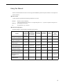
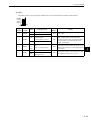
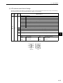
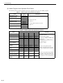
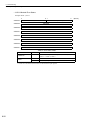
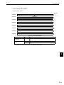
Manual Configuration
Read the chapters of this manual as required by the purpose.
Chapter
Selecting
Studying
Models and
Designing
Specifications
Peripheral
the System
and Ratings
Devices
Installation
and Wiring
Trial
Operation
Maintenance
and
Inspection
Chapter 1
Overview of the MP2200
Applicable
−
−
−
−
−
Chapter 2
System Configuration
Applicable
−
−
−
−
−
−
−
−
−
Applicable
−
Chapter 4
Module Specifications
Applicable
Applicable
Applicable
Applicable
−
−
Chapter 5
Mounting and Wiring
−
Applicable
Applicable
Applicable
−
−
Chapter 6
Basic System Operation
−
−
Applicable
−
Applicable
−
Chapter 7
Maintenance and
Inspection
−
−
−
−
−
Applicable
Chapter 8
Troubleshooting
−
−
−
−
Applicable
Applicable
Chapter 3
System Startup
iii
Visual Aids
The following aids are used to indicate certain types of information for easier reference.
IMPORTANT
Indicates important information that should be memorized.
Indicates supplemental information.
INFO
EXAMPLE
Indicates application examples.
Describes technical terms that are difficult to understand, or appear in the text without an explanation being given.
TERMS
Indication of Reverse Signals
In this manual, the names of reverse signals (ones that are valid when low) are written with a forward slash
(/) before the signal name, as shown in the following example:
• S-ON
= /S-ON
• P-CON
= /P-CON
Copyrights
• MECHATROLINK is a trademark of the MECHATROLINK Members Assciation.
• DeviceNet is a registered trademark of the ODVA (Open DeviceNet Venders Association).
• PROFIBUS is a trademark of the PROFIBUS User Organization.
• Ethernet is a registered trademark of the Xerox Corporation.
• Microsoft, Windows, Windows NT, and Internet Explorer are registered trademarks of the Microsoft Corporation.
• Pentium is a registered trademark of the Intel Corporation.
• Other product names and company names are the trademarks or registered trademarks of the respective company. “TM”
and the mark do not appear with product or company names in this manual.
iv
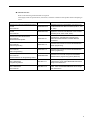
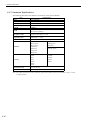
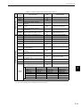
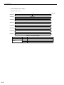
Related Manuals
Refer to the following related manuals as required.
Thoroughly check the specifications, restrictions, and other conditions of the product before attempting to
use it.
Manual Name
Manual Number
Contents
Machine Controller MP2200/MP2300 Motion
Module
User’s Manual
SIEPC88070016
Describes functions, specifications, and how to use
the MP2200/MP2300 Motion Modules (SVB-01, SVA01, SVR).
Machine Controller MP2300 Communication
Module
User’s Manual
SIEPC88070004
Describes the functions, specifications, and
application methods of the MP2200 Communication
Modules (217IF, 218IF, 260IF, 261IF).
Machine Controller MP900 Series
User’s Manual
MECHATROLINK System
SIEZ-C887-5.1
Describes the communication functions,
specifications, and application methods of the
MECHATORLINK Modules for MP900 Machine
Controllers.
Machine Controller MP900 Series
User's Manual
Ladder Programming
SIEZ-C887-1.2
Describes the instructions used in MP900/MP2000
ladder programming.
Machine Controller MP
User's Manual
Motion Programming
SIEZ-C887-1.3
Describes the instructions used in MP900/MP2000
motion programming.
Machine Controller MP900/MP2000 Series
User’s Manual
MPE720 Software for Programming Device
SIEPC88070005
Describes how to install and operate the MP900/
MP2000 Series programming system (MPE720).
Machine Controller MP900 Series
New Ladder Editor
Programming Manual
SIE-C887-13.1
Describes the programming instructions of the New
Ladder Editor, which assists MP900/MP2000 Series
design and maintenance.
Machine Controller MP900 Series
New Ladder Editor
User’s Manual
SIE-C887-13.2
Describes the operating methods of the New Ladder
Editor, which assists MP900/MP2000 Series design
and maintenance.
v
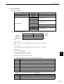
Safety Information
The following conventions are used to indicate precautions in this manual. Failure to heed precautions provided in this manual can result in serious or possibly even fatal injury or damage to the products or to related
equipment and systems.
WARNING
CAUTION
Indicates precautions that, if not heeded, could possibly result in loss of life or serious
injury.
Indicates precautions that, if not heeded, could result in relatively serious or minor
injury, damage to the product, or faulty operation.
In some situations, the precautions indicated could have serious consequences if not heeded.
PROHIBITED
Indicates prohibited actions that must not be performed. For example, this symbol
would be used as follows to indicate that fire is prohibited:
MANDATORY
Indicates compulsory actions that must be performed. For example, this symbol would
be used as follows to indicate that grounding is compulsory:
vi
.
.
Safety Precautions
The following precautions are for checking products on delivery, storage, transportation, installation, wiring,
operation, maintenance, inspection, and disposal. These precautions are important and must be observed.
WARNING
• Before starting operation in combination with the machine, ensure that an emergency stop procedure
has been provided and is working correctly.
There is a risk of injury.
• Do not touch anything inside the MP2200.
There is a risk of electrical shock.
• Always keep the front cover attached when power is being supplied.
There is a risk of electrical shock.
• Observe all procedures and precautions given in this manual for trial operation.
Operating mistakes while the servomotor and machine are connected can cause damage to the machine or even
accidents resulting in injury or death.
• Do not remove the front cover, cables, connector, or options while power is being supplied.
There is a risk of electrical shock.
• Do not allow installation, disassembly, or repairs to be performed by anyone other than specified personnel.
There is a risk of electrical shock or injury.
• Do not damage, pull on, apply excessive force to, place heavy objects on, or pinch cables.
There is a risk of electrical shock, operational failure or burning of the MP2200.
• Do not attempt to modify the MP2200 in any way.
There is a risk of injury or device damage.
• Do not approach the machine when there is a momentary interruption to the power supply. When
power is restored, the machine may start operation suddenly. Provide suitable safety measures to
protect people when operation restarts.
There is a risk of injury.
vii
Storage and Transportation
CAUTION
• Do not store or install the MP2200 in the following locations.
There is a risk of fire, electrical shock, or device damage.
• Direct sunlight
• Ambient temperature exceeds the storage or operating conditions
• Ambient humidity exceeds the storage or operating conditions
• Rapid changes in temperature or locations subject to condensation
• Corrosive or flammable gas
• Excessive dust, dirt, salt, or metallic powder
• Water, oil, or chemicals
• Vibration or shock
• Do not overload the MP2200 during transportation.
There is a risk of injury or an accident.
Installation
CAUTION
• Never use the MP2200 in locations subject to water, corrosive atmospheres, or flammable gas, or
near burnable objects.
There is a risk of electrical shock or fire.
• Do not step on the MP2200 or place heavy objects on the MP2200.
There is a risk of injury.
• Do not block the air exhaust port or allow foreign objects to enter the MP2200.
There is a risk of element deterioration inside, an accident, or fire.
• Always mount the MP2200 in the specified orientation.
There is a risk of an accident.
• Do not subject the MP2200 to strong shock.
There is a risk of an accident.
viii
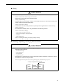
Wiring
CAUTION
• Check the wiring to be sure it has been performed correctly.
There is a risk of motor run-away, injury, or an accident.
• Always use a power supply of the specified voltage.
There is a risk of burning.
• In places with poor power supply conditions, take all steps necessary to ensure that the input power
supply is within the specified voltage range.
There is a risk of device damage.
• Install breakers and other safety measure to provide protection against shorts in external wiring.
There is a risk of fire.
• Provide sufficient shielding when using the MP2200 in the following locations.
There is a risk of device damage.
• Noise, such as from static electricity
• Strong electromagnetic or magnetic fields
• Radiation
• Near to power lines
• When connecting the battery, connect the polarity correctly.
There is a risk of battery damage or explosion.
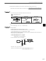
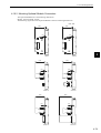
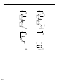
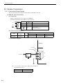
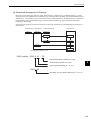
Selecting, Separating, and Laying External Cables
CAUTION
• Consider the following items when selecting the I/O signal lines (external cables) to connect the
MP2200 to external devices.
• Mechanical strength
• Noise interference
• Wiring distance
• Signal voltage, etc.
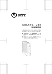
• Separate the I/O signal lines from the power lines both inside and outside the control box to reduce
the influence of noise from the power lines.
If the I/O signal lines and power lines are not separated properly, malfunctioning may result.
Example
of Separated External Cables
外部配線の分離例
Steel
separator
鉄板製のセパレータ
Power
circuit
動力回路の
cables
ケーブル
General
control
cir一般制御回路
cuit
cables
のケーブル
Digital I/O
ディジタル
signal
入出力信号
cables
ケーブル
ix
Maintenance and Inspection Precautions
CAUTION
• Do not attempt to disassemble the MP2200.
There is a risk of electrical shock or injury.
• Do not change wiring while power is being supplied.
There is a risk of electrical shock or injury.
• When replacing the MP2200, restart operation only after transferring the programs and parameters
from the old Module to the new Module.
There is a risk of device damage.
Disposal Precautions
CAUTION
• Dispose of the MP2200 as general industrial waste.
x
CONTENTS
Using this Manual - - - - - - - - - - - - - - - - - - - - - - - - - - - - - - - - - - - - - - - - - - - - - - - - - - - - - - - iii
Safety Information - - - - - - - - - - - - - - - - - - - - - - - - - - - - - - - - - - - - - - - - - - - - - - - - - - - - - - - vi
Safety Precautions - - - - - - - - - - - - - - - - - - - - - - - - - - - - - - - - - - - - - - - - - - - - - - - - - - - - - - vii
1 Outline of MP2200
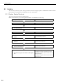
1.1 Features - - - - - - - - - - - - - - - - - - - - - - - - - - - - - - - - - - - - - - - - - - - - - - - - - - - 1-2
1.2 Module Appearance - - - - - - - - - - - - - - - - - - - - - - - - - - - - - - - - - - - - - - - - - - - 1-3
1.2.1 Basic Unit - - - - - - - - - - - - - - - - - - - - - - - - - - - - - - - - - - - - - - - - - - - - - - - - - - - - - - - - - - - - 1-3
1.2.2 Modules - - - - - - - - - - - - - - - - - - - - - - - - - - - - - - - - - - - - - - - - - - - - - - - - - - - - - - - - - - - - - 1-4
2 System Configuration
2.1 System Configuration - - - - - - - - - - - - - - - - - - - - - - - - - - - - - - - - - - - - - - - - - - 2-2
2.1.1 Basic System Configuration - - - - - - - - - - - - - - - - - - - - - - - - - - - - - - - - - - - - - - - - - - - - - - - 2-2
2.1.2 System Configuration Precautions - - - - - - - - - - - - - - - - - - - - - - - - - - - - - - - - - - - - - - - - - - 2-4
2.2 List of Modules - - - - - - - - - - - - - - - - - - - - - - - - - - - - - - - - - - - - - - - - - - - - - - - 2-5
2.2.1 MP2200 Modules - - - - - - - - - - - - - - - - - - - - - - - - - - - - - - - - - - - - - - - - - - - - - - - - - - - - - - 2-5
2.3 Devices Connectable to MECHATROLINK - - - - - - - - - - - - - - - - - - - - - - - - - - - 2-6
2.4 Cables and Accessories - - - - - - - - - - - - - - - - - - - - - - - - - - - - - - - - - - - - - - - - 2-7
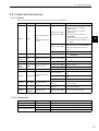
2.4.1 Cables - - - - - - - - - - - - - - - - - - - - - - - - - - - - - - - - - - - - - - - - - - - - - - - - - - - - - - - - - - - - - - 2-7
2.4.2 Accessories - - - - - - - - - - - - - - - - - - - - - - - - - - - - - - - - - - - - - - - - - - - - - - - - - - - - - - - - - - 2-7
2.5 Software - - - - - - - - - - - - - - - - - - - - - - - - - - - - - - - - - - - - - - - - - - - - - - - - - - - 2-8
2.5.1 Software for Programming Devices - - - - - - - - - - - - - - - - - - - - - - - - - - - - - - - - - - - - - - - - - - 2-8
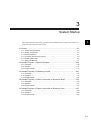
3 System Startup
3.1 Outline- - - - - - - - - - - - - - - - - - - - - - - - - - - - - - - - - - - - - - - - - - - - - - - - - - - - - 3-2
3.1.1 System Startup Flowchart- - - - - - - - - - - - - - - - - - - - - - - - - - - - - - - - - - - - - - - - - - - - - - - - - 3-2
3.1.2 System Configuration - - - - - - - - - - - - - - - - - - - - - - - - - - - - - - - - - - - - - - - - - - - - - - - - - - - 3-3
3.1.3 Device Preparation - - - - - - - - - - - - - - - - - - - - - - - - - - - - - - - - - - - - - - - - - - - - - - - - - - - - - 3-4
3.1.4 Connecting and Wiring the System - - - - - - - - - - - - - - - - - - - - - - - - - - - - - - - - - - - - - - - - - - 3-6
3.1.5 Initializing the System - - - - - - - - - - - - - - - - - - - - - - - - - - - - - - - - - - - - - - - - - - - - - - - - - - - 3-8
3.1.6 Starting the MPE720 - - - - - - - - - - - - - - - - - - - - - - - - - - - - - - - - - - - - - - - - - - - - - - - - - - - 3-11
3.2 Sample Program 1: Manual Operation - - - - - - - - - - - - - - - - - - - - - - - - - - - - - 3-36
3.2.1 Description - - - - - - - - - - - - - - - - - - - - - - - - - - - - - - - - - - - - - - - - - - - - - - - - - - - - - - - - - - 3-36
3.2.2 Operation - - - - - - - - - - - - - - - - - - - - - - - - - - - - - - - - - - - - - - - - - - - - - - - - - - - - - - - - - - - 3-37
3.2.3 Program Details - - - - - - - - - - - - - - - - - - - - - - - - - - - - - - - - - - - - - - - - - - - - - - - - - - - - - - 3-40
3.3 Sample Program 2: Positioning Control - - - - - - - - - - - - - - - - - - - - - - - - - - - - 3-47
3.3.1 Description - - - - - - - - - - - - - - - - - - - - - - - - - - - - - - - - - - - - - - - - - - - - - - - - - - - - - - - - - - 3-47
3.3.2 Operation - - - - - - - - - - - - - - - - - - - - - - - - - - - - - - - - - - - - - - - - - - - - - - - - - - - - - - - - - - - 3-48
3.3.3 Program Details - - - - - - - - - - - - - - - - - - - - - - - - - - - - - - - - - - - - - - - - - - - - - - - - - - - - - - 3-50
xi
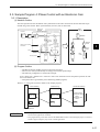
3.4 Sample Program 3: Phase Control with an Electronic Shaft - - - - - - - - - - - - - - 3-52
3.4.1 Description- - - - - - - - - - - - - - - - - - - - - - - - - - - - - - - - - - - - - - - - - - - - - - - - - - - - - - - - - - - 3-52
3.4.2 Operation- - - - - - - - - - - - - - - - - - - - - - - - - - - - - - - - - - - - - - - - - - - - - - - - - - - - - - - - - - - - 3-53
3.4.3 Program Details - - - - - - - - - - - - - - - - - - - - - - - - - - - - - - - - - - - - - - - - - - - - - - - - - - - - - - - 3-55
3.5 Sample Program 4: Phase Control with an Electronic Cam- - - - - - - - - - - - - - - 3-57
3.5.1 Description- - - - - - - - - - - - - - - - - - - - - - - - - - - - - - - - - - - - - - - - - - - - - - - - - - - - - - - - - - - 3-57
3.5.2 Operation- - - - - - - - - - - - - - - - - - - - - - - - - - - - - - - - - - - - - - - - - - - - - - - - - - - - - - - - - - - - 3-58
3.5.3 Program Details - - - - - - - - - - - - - - - - - - - - - - - - - - - - - - - - - - - - - - - - - - - - - - - - - - - - - - - 3-60
4 Module Specifications
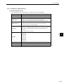
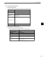
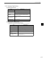
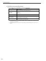
4.1 General Specifications - - - - - - - - - - - - - - - - - - - - - - - - - - - - - - - - - - - - - - - - - 4-3
4.1.1 Hardware Specifications - - - - - - - - - - - - - - - - - - - - - - - - - - - - - - - - - - - - - - - - - - - - - - - - - -4-3
4.1.2 Function List - - - - - - - - - - - - - - - - - - - - - - - - - - - - - - - - - - - - - - - - - - - - - - - - - - - - - - - - - -4-4
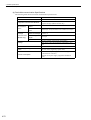
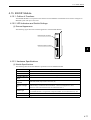
4.2 Base Unit- - - - - - - - - - - - - - - - - - - - - - - - - - - - - - - - - - - - - - - - - - - - - - - - - - - 4-5
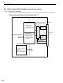
4.2.1 Outline of Functions - - - - - - - - - - - - - - - - - - - - - - - - - - - - - - - - - - - - - - - - - - - - - - - - - - - - -4-5
4.2.2 LED Indicators - - - - - - - - - - - - - - - - - - - - - - - - - - - - - - - - - - - - - - - - - - - - - - - - - - - - - - - - -4-5
4.2.3 Hardware Specifications - - - - - - - - - - - - - - - - - - - - - - - - - - - - - - - - - - - - - - - - - - - - - - - - - -4-6
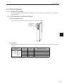
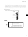
4.3 CPU-01 Module - - - - - - - - - - - - - - - - - - - - - - - - - - - - - - - - - - - - - - - - - - - - - - 4-7
4.3.1 Outline of Functions - - - - - - - - - - - - - - - - - - - - - - - - - - - - - - - - - - - - - - - - - - - - - - - - - - - - -4-7
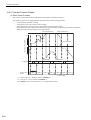
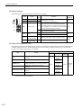
4.3.2 LED Indicators and Switch Settings - - - - - - - - - - - - - - - - - - - - - - - - - - - - - - - - - - - - - - - - - -4-7
4.3.3 Hardware Specifications - - - - - - - - - - - - - - - - - - - - - - - - - - - - - - - - - - - - - - - - - - - - - - - - - -4-9
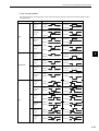
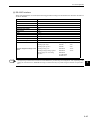
4.3.4 Functions and Specifications - - - - - - - - - - - - - - - - - - - - - - - - - - - - - - - - - - - - - - - - - - - - - - 4-10
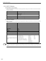
4.4 CPU-02 Module - - - - - - - - - - - - - - - - - - - - - - - - - - - - - - - - - - - - - - - - - - - - - 4-13
4.4.1 Outline of Functions - - - - - - - - - - - - - - - - - - - - - - - - - - - - - - - - - - - - - - - - - - - - - - - - - - - - 4-13
4.4.2 LED Indicators and Switch Settings - - - - - - - - - - - - - - - - - - - - - - - - - - - - - - - - - - - - - - - - - 4-13
4.4.3 Hardware Specifications - - - - - - - - - - - - - - - - - - - - - - - - - - - - - - - - - - - - - - - - - - - - - - - - - 4-16
4.4.4 Compact Flash Interface - - - - - - - - - - - - - - - - - - - - - - - - - - - - - - - - - - - - - - - - - - - - - - - - - 4-17
4.4.5 USB Interface- - - - - - - - - - - - - - - - - - - - - - - - - - - - - - - - - - - - - - - - - - - - - - - - - - - - - - - - - 4-23
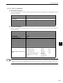
4.5 SVB-01 Module - - - - - - - - - - - - - - - - - - - - - - - - - - - - - - - - - - - - - - - - - - - - - 4-33
4.5.1 Outline of Functions - - - - - - - - - - - - - - - - - - - - - - - - - - - - - - - - - - - - - - - - - - - - - - - - - - - - 4-33
4.5.2 LED Indicators and Switch Settings - - - - - - - - - - - - - - - - - - - - - - - - - - - - - - - - - - - - - - - - - 4-33
4.5.3 Hardware Specifications - - - - - - - - - - - - - - - - - - - - - - - - - - - - - - - - - - - - - - - - - - - - - - - - - 4-35
4.5.4 Function Lists - - - - - - - - - - - - - - - - - - - - - - - - - - - - - - - - - - - - - - - - - - - - - - - - - - - - - - - - - 4-36
4.6 SVA-01 Module - - - - - - - - - - - - - - - - - - - - - - - - - - - - - - - - - - - - - - - - - - - - - 4-38
4.6.1 Outline of Functions - - - - - - - - - - - - - - - - - - - - - - - - - - - - - - - - - - - - - - - - - - - - - - - - - - - - 4-38
4.6.2 LED Indicators and Switch Settings - - - - - - - - - - - - - - - - - - - - - - - - - - - - - - - - - - - - - - - - - 4-38
4.6.3 Hardware Specifications - - - - - - - - - - - - - - - - - - - - - - - - - - - - - - - - - - - - - - - - - - - - - - - - - 4-39
4.6.4 Function Lists - - - - - - - - - - - - - - - - - - - - - - - - - - - - - - - - - - - - - - - - - - - - - - - - - - - - - - - - - 4-40
4.7 LIO-01 Module - - - - - - - - - - - - - - - - - - - - - - - - - - - - - - - - - - - - - - - - - - - - - - 4-42
4.7.1 Outline of Functions - - - - - - - - - - - - - - - - - - - - - - - - - - - - - - - - - - - - - - - - - - - - - - - - - - - - 4-42
4.7.2 LED Indicators and Switch Settings - - - - - - - - - - - - - - - - - - - - - - - - - - - - - - - - - - - - - - - - - 4-42
4.7.3 Hardware Specifications - - - - - - - - - - - - - - - - - - - - - - - - - - - - - - - - - - - - - - - - - - - - - - - - - 4-44
xii
4.8 LIO-02 Module - - - - - - - - - - - - - - - - - - - - - - - - - - - - - - - - - - - - - - - - - - - - - - 4-45
4.8.1 Outline of Functions- - - - - - - - - - - - - - - - - - - - - - - - - - - - - - - - - - - - - - - - - - - - - - - - - - - - 4-45
4.8.2 LED Indicators and Switch Settings- - - - - - - - - - - - - - - - - - - - - - - - - - - - - - - - - - - - - - - - - 4-45
4.8.3 Hardware Specifications- - - - - - - - - - - - - - - - - - - - - - - - - - - - - - - - - - - - - - - - - - - - - - - - - 4-47
4.9 LIO-01 and LIO-02 Module Counter Functions - - - - - - - - - - - - - - - - - - - - - - - 4-48
4.9.1 Outline of Functions- - - - - - - - - - - - - - - - - - - - - - - - - - - - - - - - - - - - - - - - - - - - - - - - - - - - 4-48
4.9.2 Counter Function Details - - - - - - - - - - - - - - - - - - - - - - - - - - - - - - - - - - - - - - - - - - - - - - - - 4-50
4.9.3 Electronic Gear Function - - - - - - - - - - - - - - - - - - - - - - - - - - - - - - - - - - - - - - - - - - - - - - - - 4-54
4.9.4 Counter Parameters - - - - - - - - - - - - - - - - - - - - - - - - - - - - - - - - - - - - - - - - - - - - - - - - - - - 4-58
4.10 LIO-04 Module - - - - - - - - - - - - - - - - - - - - - - - - - - - - - - - - - - - - - - - - - - - - - 4-61
4.10.1 Outline of Functions - - - - - - - - - - - - - - - - - - - - - - - - - - - - - - - - - - - - - - - - - - - - - - - - - - - 4-61
4.10.2 LED Indicators and Switch Settings - - - - - - - - - - - - - - - - - - - - - - - - - - - - - - - - - - - - - - - - 4-61
4.10.3 Hardware Specifications- - - - - - - - - - - - - - - - - - - - - - - - - - - - - - - - - - - - - - - - - - - - - - - - 4-62
4.11 218IF-01 Module- - - - - - - - - - - - - - - - - - - - - - - - - - - - - - - - - - - - - - - - - - - - 4-63
4.11.1 Outline of Functions - - - - - - - - - - - - - - - - - - - - - - - - - - - - - - - - - - - - - - - - - - - - - - - - - - - 4-63
4.11.2 LED Indicators and Switch Settings - - - - - - - - - - - - - - - - - - - - - - - - - - - - - - - - - - - - - - - - 4-63
4.11.3 Hardware Specifications - - - - - - - - - - - - - - - - - - - - - - - - - - - - - - - - - - - - - - - - - - - - - - - - 4-65
4.12 217IF-01 Module - - - - - - - - - - - - - - - - - - - - - - - - - - - - - - - - - - - - - - - - - - - 4-66
4.12.1 Outline of Functions - - - - - - - - - - - - - - - - - - - - - - - - - - - - - - - - - - - - - - - - - - - - - - - - - - - 4-66
4.12.2 LED Indicators and Switch Settings - - - - - - - - - - - - - - - - - - - - - - - - - - - - - - - - - - - - - - - - 4-66
4.12.3 Hardware Specifications- - - - - - - - - - - - - - - - - - - - - - - - - - - - - - - - - - - - - - - - - - - - - - - - 4-68
4.13 260IF-01 Module - - - - - - - - - - - - - - - - - - - - - - - - - - - - - - - - - - - - - - - - - - - 4-69
4.13.1 Outline of Functions - - - - - - - - - - - - - - - - - - - - - - - - - - - - - - - - - - - - - - - - - - - - - - - - - - - 4-69
4.13.2 LED Indicators and Switch Settings - - - - - - - - - - - - - - - - - - - - - - - - - - - - - - - - - - - - - - - - 4-69
4.13.3 Hardware Specifications- - - - - - - - - - - - - - - - - - - - - - - - - - - - - - - - - - - - - - - - - - - - - - - - 4-71
4.14 261IF-01 Module - - - - - - - - - - - - - - - - - - - - - - - - - - - - - - - - - - - - - - - - - - - 4-73
4.14.1 Outline of Functions - - - - - - - - - - - - - - - - - - - - - - - - - - - - - - - - - - - - - - - - - - - - - - - - - - - 4-73
4.14.2 LED Indicators and Switch Settings - - - - - - - - - - - - - - - - - - - - - - - - - - - - - - - - - - - - - - - - 4-73
4.14.3 Hardware Specifications- - - - - - - - - - - - - - - - - - - - - - - - - - - - - - - - - - - - - - - - - - - - - - - - 4-75
4.15 EXIOIF Module- - - - - - - - - - - - - - - - - - - - - - - - - - - - - - - - - - - - - - - - - - - - - 4-77
4.15.1 Outline of Functions - - - - - - - - - - - - - - - - - - - - - - - - - - - - - - - - - - - - - - - - - - - - - - - - - - - 4-77
4.15.2 LED Indicators and Switch Settings - - - - - - - - - - - - - - - - - - - - - - - - - - - - - - - - - - - - - - - - 4-77
4.15.3 Hardware Specifications- - - - - - - - - - - - - - - - - - - - - - - - - - - - - - - - - - - - - - - - - - - - - - - - 4-77
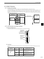
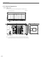
4.16 External Appearance- - - - - - - - - - - - - - - - - - - - - - - - - - - - - - - - - - - - - - - - - 4-78
4.16.1 Basic Unit - - - - - - - - - - - - - - - - - - - - - - - - - - - - - - - - - - - - - - - - - - - - - - - - - - - - - - - - - - 4-78
4.16.2 Mounting Optional Module Connectors - - - - - - - - - - - - - - - - - - - - - - - - - - - - - - - - - - - - - 4-79
5 Mounting and Wiring
5.1 Handling the MP2200 - - - - - - - - - - - - - - - - - - - - - - - - - - - - - - - - - - - - - - - - - - 5-2
5.1.1 Mounting the MP2200 - - - - - - - - - - - - - - - - - - - - - - - - - - - - - - - - - - - - - - - - - - - - - - - - - - - 5-2
5.1.2 Replacing and Adding Optional Modules - - - - - - - - - - - - - - - - - - - - - - - - - - - - - - - - - - - - - - 5-5
xiii
5.2 Module Connections - - - - - - - - - - - - - - - - - - - - - - - - - - - - - - - - - - - - - - - - - - - 5-8
5.2.1 Connecting Power Supply - - - - - - - - - - - - - - - - - - - - - - - - - - - - - - - - - - - - - - - - - - - - - - - - -5-8
5.2.2 SVB-01 Module Connections - - - - - - - - - - - - - - - - - - - - - - - - - - - - - - - - - - - - - - - - - - - - - - 5-11
5.2.3 SVA-01 Module Connections - - - - - - - - - - - - - - - - - - - - - - - - - - - - - - - - - - - - - - - - - - - - - - 5-17
5.2.4 LIO Module Connections - - - - - - - - - - - - - - - - - - - - - - - - - - - - - - - - - - - - - - - - - - - - - - - - - 5-25
5.2.5 LIO-04 Module Connections - - - - - - - - - - - - - - - - - - - - - - - - - - - - - - - - - - - - - - - - - - - - - - 5-37
5.2.6 218IF-01 Module Connections - - - - - - - - - - - - - - - - - - - - - - - - - - - - - - - - - - - - - - - - - - - - - 5-47
5.2.7 217IF-01 Module Connections - - - - - - - - - - - - - - - - - - - - - - - - - - - - - - - - - - - - - - - - - - - - - 5-51
5.2.8 260IF-01 Module Connections - - - - - - - - - - - - - - - - - - - - - - - - - - - - - - - - - - - - - - - - - - - - - 5-55
5.2.9 261IF-01 Module Connections - - - - - - - - - - - - - - - - - - - - - - - - - - - - - - - - - - - - - - - - - - - - - 5-58
5.2.10 EXIOIF Module Connections - - - - - - - - - - - - - - - - - - - - - - - - - - - - - - - - - - - - - - - - - - - - - 5-61
6 Basic System Operation
6.1 Operating Mode - - - - - - - - - - - - - - - - - - - - - - - - - - - - - - - - - - - - - - - - - - - - - - 6-2
6.1.1 Online Operating Mode - - - - - - - - - - - - - - - - - - - - - - - - - - - - - - - - - - - - - - - - - - - - - - - - - - -6-2
6.1.2 Offline Stop Mode - - - - - - - - - - - - - - - - - - - - - - - - - - - - - - - - - - - - - - - - - - - - - - - - - - - - - - -6-2
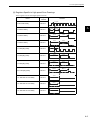
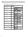
6.2 Startup Sequence and Basic Operation - - - - - - - - - - - - - - - - - - - - - - - - - - - - - 6-3
6.2.1 DIP Switch Settings - - - - - - - - - - - - - - - - - - - - - - - - - - - - - - - - - - - - - - - - - - - - - - - - - - - - -6-3
6.2.2 Indicator Patterns - - - - - - - - - - - - - - - - - - - - - - - - - - - - - - - - - - - - - - - - - - - - - - - - - - - - - - -6-4
6.2.3 Startup Sequence - - - - - - - - - - - - - - - - - - - - - - - - - - - - - - - - - - - - - - - - - - - - - - - - - - - - - - -6-5
6.3 User Program- - - - - - - - - - - - - - - - - - - - - - - - - - - - - - - - - - - - - - - - - - - - - - - - 6-7
6.3.1 Drawings (DWGs)- - - - - - - - - - - - - - - - - - - - - - - - - - - - - - - - - - - - - - - - - - - - - - - - - - - - - - -6-7
6.3.2 Execution Control of Drawings - - - - - - - - - - - - - - - - - - - - - - - - - - - - - - - - - - - - - - - - - - - - - -6-8
6.3.3 Motion Programs - - - - - - - - - - - - - - - - - - - - - - - - - - - - - - - - - - - - - - - - - - - - - - - - - - - - - - 6-11
6.3.4 Functions - - - - - - - - - - - - - - - - - - - - - - - - - - - - - - - - - - - - - - - - - - - - - - - - - - - - - - - - - - - - 6-19
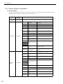
6.4 Registers - - - - - - - - - - - - - - - - - - - - - - - - - - - - - - - - - - - - - - - - - - - - - - - - - - 6-20
6.4.1 Data Types - - - - - - - - - - - - - - - - - - - - - - - - - - - - - - - - - - - - - - - - - - - - - - - - - - - - - - - - - - 6-20
6.4.2 Types of Registers - - - - - - - - - - - - - - - - - - - - - - - - - - - - - - - - - - - - - - - - - - - - - - - - - - - - - 6-23
6.4.3 Register Designation Methods - - - - - - - - - - - - - - - - - - - - - - - - - - - - - - - - - - - - - - - - - - - - - 6-26
6.4.4 Subscripts i and j - - - - - - - - - - - - - - - - - - - - - - - - - - - - - - - - - - - - - - - - - - - - - - - - - - - - - - 6-27
6.5 Self-configuration - - - - - - - - - - - - - - - - - - - - - - - - - - - - - - - - - - - - - - - - - - - - 6-29
6.5.1 Overview of Self-configuration - - - - - - - - - - - - - - - - - - - - - - - - - - - - - - - - - - - - - - - - - - - - - 6-29
6.5.2 SVB-01 Modules - - - - - - - - - - - - - - - - - - - - - - - - - - - - - - - - - - - - - - - - - - - - - - - - - - - - - - 6-30
6.5.3 SVA-01 Modules- - - - - - - - - - - - - - - - - - - - - - - - - - - - - - - - - - - - - - - - - - - - - - - - - - - - - - - 6-39
6.5.4 LIO-01 Modules - - - - - - - - - - - - - - - - - - - - - - - - - - - - - - - - - - - - - - - - - - - - - - - - - - - - - - - 6-40
6.5.5 LIO-02 Modules - - - - - - - - - - - - - - - - - - - - - - - - - - - - - - - - - - - - - - - - - - - - - - - - - - - - - - - 6-41
6.5.6 LIO-04 Modules - - - - - - - - - - - - - - - - - - - - - - - - - - - - - - - - - - - - - - - - - - - - - - - - - - - - - - - 6-42
6.5.7 218IF-01 Modules- - - - - - - - - - - - - - - - - - - - - - - - - - - - - - - - - - - - - - - - - - - - - - - - - - - - - - 6-43
6.5.8 217IF-01 Modules- - - - - - - - - - - - - - - - - - - - - - - - - - - - - - - - - - - - - - - - - - - - - - - - - - - - - - 6-44
6.5.9 260IF-01 Modules- - - - - - - - - - - - - - - - - - - - - - - - - - - - - - - - - - - - - - - - - - - - - - - - - - - - - - 6-46
6.5.10 261IF-01 Modules- - - - - - - - - - - - - - - - - - - - - - - - - - - - - - - - - - - - - - - - - - - - - - - - - - - - - 6-47
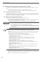
6.6 Setting and Changing User-defined Files or Data - - - - - - - - - - - - - - - - - - - - - 6-48
6.6.1 Saving User-defined Files or Data - - - - - - - - - - - - - - - - - - - - - - - - - - - - - - - - - - - - - - - - - - 6-48
6.6.2 Setting and Changing the Scan Times - - - - - - - - - - - - - - - - - - - - - - - - - - - - - - - - - - - - - - - 6-48
6.6.3 Setting and Changing the Module Configuration Definition - - - - - - - - - - - - - - - - - - - - - - - - - 6-49
xiv
7 Maintenance and Inspection
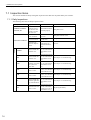
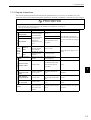
7.1 Inspection Items - - - - - - - - - - - - - - - - - - - - - - - - - - - - - - - - - - - - - - - - - - - - - - 7-2
7.1.1 Daily Inspections - - - - - - - - - - - - - - - - - - - - - - - - - - - - - - - - - - - - - - - - - - - - - - - - - - - - - - - 7-2
7.1.2 Regular Inspections - - - - - - - - - - - - - - - - - - - - - - - - - - - - - - - - - - - - - - - - - - - - - - - - - - - - - 7-3
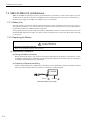
7.2 MBU-01/MBU-02 Unit Batteries - - - - - - - - - - - - - - - - - - - - - - - - - - - - - - - - - - - 7-4
7.2.1 Battery Life - - - - - - - - - - - - - - - - - - - - - - - - - - - - - - - - - - - - - - - - - - - - - - - - - - - - - - - - - - - 7-4
7.2.2 Replacing the Battery - - - - - - - - - - - - - - - - - - - - - - - - - - - - - - - - - - - - - - - - - - - - - - - - - - - 7-4
8 Troubleshooting
8.1 Overview of Troubleshooting - - - - - - - - - - - - - - - - - - - - - - - - - - - - - - - - - - - - - 8-2
8.1.1 Troubleshooting Methods - - - - - - - - - - - - - - - - - - - - - - - - - - - - - - - - - - - - - - - - - - - - - - - - - 8-2
8.1.2 Basic Troubleshooting Flow - - - - - - - - - - - - - - - - - - - - - - - - - - - - - - - - - - - - - - - - - - - - - - - 8-3
8.1.3 Indicator Errors - - - - - - - - - - - - - - - - - - - - - - - - - - - - - - - - - - - - - - - - - - - - - - - - - - - - - - - - 8-3
8.2 System Errors - - - - - - - - - - - - - - - - - - - - - - - - - - - - - - - - - - - - - - - - - - - - - - - 8-5
8.2.1 Overview of System Errors - - - - - - - - - - - - - - - - - - - - - - - - - - - - - - - - - - - - - - - - - - - - - - - - 8-5
8.2.2 Processing Flow When a System Error Occurs - - - - - - - - - - - - - - - - - - - - - - - - - - - - - - - - - 8-6
8.2.3 Processing Flow for a User Program Error - - - - - - - - - - - - - - - - - - - - - - - - - - - - - - - - - - - - - 8-7
8.2.4 System Register Configuration - - - - - - - - - - - - - - - - - - - - - - - - - - - - - - - - - - - - - - - - - - - - - 8-8
Appendices
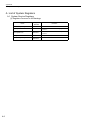
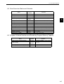
A List of System Registers - - - - - - - - - - - - - - - - - - - - - - - - - - - - - - - - - - - - - - - - - A-2
A.1 System Service Registers- - - - - - - - - - - - - - - - - - - - - - - - - - - - - - - - - - - - - - - - - - - - - - - - - - A-2
A.2 Scan Execution Status and Calendar - - - - - - - - - - - - - - - - - - - - - - - - - - - - - - - - - - - - - - - - - - A-5
A.3 Program Software Numbers and Remaining Program Memory Capacity - - - - - - - - - - - - - - - - - A-5
INDEX
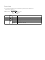
Revision History
xv
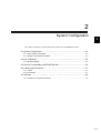
1
1
Outline of MP2200
This chapter provides an overview and describes the features of the MP2200 Machine Controller.
1.1 Features - - - - - - - - - - - - - - - - - - - - - - - - - - - - - - - - - - - - - - - - - - - - - - - 1-2
1.2 Module Appearance - - - - - - - - - - - - - - - - - - - - - - - - - - - - - - - - - - - - - - - 1-3
1.2.1 Basic Unit - - - - - - - - - - - - - - - - - - - - - - - - - - - - - - - - - - - - - - - - - - - - - - - - - - - - - - - 1-3
1.2.2 Modules - - - - - - - - - - - - - - - - - - - - - - - - - - - - - - - - - - - - - - - - - - - - - - - - - - - - - - - - 1-4
1-1
1 Outline of MP2200
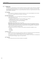
1.1 Features
The MP2200 is a high-performance, multi-axis Machine Controller for flexible system construction. In addition
to I/O and Communication Modules, it has a wide range of Optional Modules, including various Motion Modules that support a variety of motor drives. It provides ideal motion control for a range of machines, from standalone machines to FA systems.
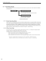
(1) Flexibility
• With an option slot configuration that enables expansion to 35 slots, Optional Modules can be selected
freely and the optimum system can be built for your machine.
(2) High Performance
• Control characteristics have been improved by increasing the CPU and Motion Network
(MECHATROLINK-II) speed.
• Completely synchronous operation can be achieved for up to 256 axes.
• MECHATROLINK-II baud rate: 2.5 times faster than MP920
• CPU processing speed: 2.0 times faster than MP920
• Larger user memory area
• High-speed (0.5 ms) motion control is now possible.
• MECHATROLINK-II enables position control, speed control, torque control, and phase control, and
makes precise synchronous control possible. The control mode can also be changed online, facilitating
complicated machine operations. The range of possible motion control applications is increased even
further with the Virtual Motion Module (SVR).
• The following open networks are supported when optional Communication Modules are used.
• Ethernet
• DeviceNet
• PROFIBUS
(3) Easy to Use
• Machine startup times can be greatly reduced by using the self-configuration function that automatically
detects devices connected to MECHATROLINK and sets the required parameters.
• The application program converter can utilize your previous software assets with their accumulated databanks of specific knowledge to improve the system further.
(4) Compact
• The mounting area has been reduced to half that of the MP920.
1-2
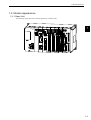
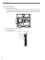
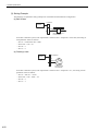
1.2 Module Appearance
1.2 Module Appearance
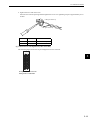
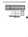
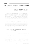
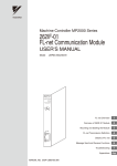
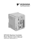
1.2.1 Basic Unit
The following figure shows the external appearance of a Basic Unit.
MP2200 MBU-01 CPU-01 218IF-01 SVB-01
POWER
LIO-01
LIO-01
LIO-02
260IF-01 217IF-01 EXIOIF
1
YASKAWA
1-3
1 Outline of MP2200
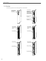
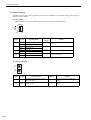
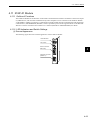
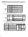
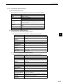
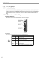
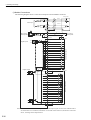
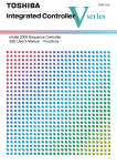
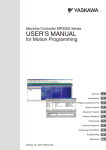
1.2.2 Modules
1.2.2 Modules
The following figures show the external appearance of the Modules.
LED indicators
DIP switch
LED indicators
CPU-01
RDY
RUN
ALM
ERR
BAT
STOP
SUP
INIT
CNFG
MON
TEST
OFF
DIP switch
Switches (station
address setting)
SVB-01
RUN
ERR
TX
M/S
SIZE
SPD
OFF
ON
10
SW1
1
ON
MECHATROLINK
connector
M-I/II
CN1
MECHATROLINK
connector
CN2
CPU-01
LED indicators
LIO-01
SVB-01
LED indicators
Switch
Switch
I/O connector
I/O connector
LIO-01
LIO-02
LIO-02
LED indicators
LED indicators
LIO-04
RUN
SVA-01
FU
RUN
CN1
ERR
CH1
Servo connector
I/O connector
CH2
24-V input connector
+24V
ON
CN2
LIO-04
1-4
DC IN
SVA-01
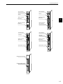
1.2 Module Appearance
LED indicators
218IF-01
LED indicators
Switch
Switch
Serial connector
(RS-232C)
Serial connector
(RS-232C)
1
Serial connector
(RS-422/485)
Ethernet connector
(10Base-T)
218IF-01
LED indicators
217IF-01
LED indicators
261IF-01
260IF-01
Switches
Switches
Serial connector
(RS-232C)
Serial connector
(RS-232C)
DeviceNet connector
PROFIBUS connector
260IF-01
External input connector
217IF-01
PROFIBUS
261IF-01
EXIOIF
External output connector
EXIOIF
1-5
2
System Configuration
2
This chapter explains the product information required to build MP2200 systems.
2.1 System Configuration - - - - - - - - - - - - - - - - - - - - - - - - - - - - - - - - - - - - - - 2-2
2.1.1 Basic System Configuration - - - - - - - - - - - - - - - - - - - - - - - - - - - - - - - - - - - - - - - - - - 2-2
2.1.2 System Configuration Precautions - - - - - - - - - - - - - - - - - - - - - - - - - - - - - - - - - - - - - 2-4
2.2 List of Modules - - - - - - - - - - - - - - - - - - - - - - - - - - - - - - - - - - - - - - - - - - - 2-5
2.2.1 MP2200 Modules - - - - - - - - - - - - - - - - - - - - - - - - - - - - - - - - - - - - - - - - - - - - - - - - - 2-5
2.3 Devices Connectable to MECHATROLINK - - - - - - - - - - - - - - - - - - - - - - - 2-6
2.4 Cables and Accessories - - - - - - - - - - - - - - - - - - - - - - - - - - - - - - - - - - - - 2-7
2.4.1 Cables - - - - - - - - - - - - - - - - - - - - - - - - - - - - - - - - - - - - - - - - - - - - - - - - - - - - - - - - - 2-7
2.4.2 Accessories - - - - - - - - - - - - - - - - - - - - - - - - - - - - - - - - - - - - - - - - - - - - - - - - - - - - - 2-7
2.5 Software - - - - - - - - - - - - - - - - - - - - - - - - - - - - - - - - - - - - - - - - - - - - - - - 2-8
2.5.1 Software for Programming Devices - - - - - - - - - - - - - - - - - - - - - - - - - - - - - - - - - - - - - 2-8
2-1
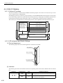
2 System Configuration
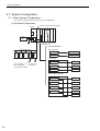
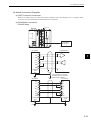
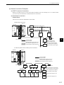
2.1.1 Basic System Configuration
2.1 System Configuration
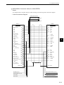
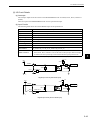
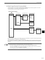
2.1.1 Basic System Configuration
The following diagram shows the basic system configuration.
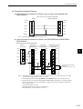
(1) One-Rack Configuration
MP2200
Slot 0 is always the CPU Module.
MP2200 MBU-02 CPU-01 SVB-01 LIO-01
24-VDC
power
supply
9 Modules max.
Optional Modules
Motion Modules
SGDS
NS115
SGDH
IO2310
PL2900
PL2910
MECHATROLINK-II
SVB-01
MECHATROLINK
SVA-01
Analog outputs
I/O Modules
M
M
MECHATROLINKServodrives
compatible I/O Modules
LIO-01
External I/O
LIO-02
External I/O
LIO-04
External I/O
Communication Modules
218IF-01
Ethernet
217IF-01
RS485/422
260IF-01
DeviceNet
261IF-01
PROFIBUS
RS-232C
2-2
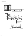
2.1 System Configuration
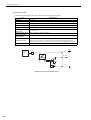
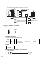
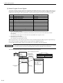
EXAMPLE
The following diagram shows an example system configuration.
MP2200
SVB-01
218IF-01
LIO-01
MP2200 MBU-02 CPU-01 SVB-01 218IF
-01
LIO-01
24-VDC
power
supply
2
External I/O
MECHATROLINK-II
M
SGDS
NS115
SGDH
IO2310
PL2900
PL2910
Control panel
RS-232C
M
MPE720
Ethernet
MECHATROLINKServodrives
compatible I/O Modules
Note: 1. Up to 21 devices can be connected to MECHATROLINK-II. (The SERVOPACKs can be connected
to up to 16 axes.)
2. Up to 32 I/O can be used (16 inputs and 16 outputs) with the LIO-01.
3. Communication Modules can be used to connect to Ethernet, DeviceNet, PROFIBUS, RS-232C,
and RS-422/485 open networks.
4. In the above example, a 218IF-01 Module is used. The MPE720 is connected to Ethernet and a
Human-Machine Interface (HMI) is connected to RS-232C.
2-3
2 System Configuration
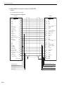
2.1.2 System Configuration Precautions
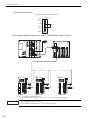
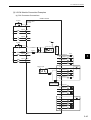
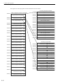
(2) Maximum Four-Rack Configuration
Slot 0 (always CPU Module)
Slot 8
Optional Modules
24 VDC
or
100/200
VAC
External I/O Modules
Slot 9
LIO-01
LIO-02
LIO-04
Slot 1
External I/O
External I/O
Slot 1
217IF-01
261IF-01
260IF-01
218IF-01
Communication Modules
RS-232C
MMI
Ethernet
MPE720
DeviceNet
PROFIBUS
Slot 9
RS-422/485
Slot 1
SVB-01
SVA-01
Motion Modules
SERVOPACK
M
PG
Slot 9
SVB-01
Distributed I/O Modules *
External output
External input
* A distributed I/O function is provided by the SVB-01 Modules through MECHATROLINK communication.
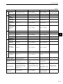
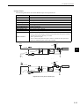
2.1.2 System Configuration Precautions
The following precautions must be followed when designing a system using the MP2200.
• Use the connecting cables and connectors recommended by Yaskawa. Yaskawa has a range of cables.
Always check the device to be used and select the correct cable for the device.
• Different SERVOPACKs are connected to MECHATROLINK-I and MECHATROLINK-II. Refer to the
list and select the appropriate SERVOPACKs.
• The user must supply the 24-VDC power supply.
• The battery backs up M registers, system registers, and trace memory. Always save the program to flash
memory whenever it is input or changed.
2-4
2.2 List of Modules
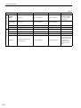
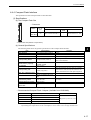
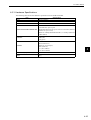
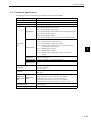
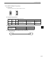
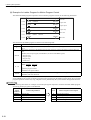
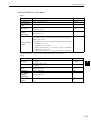
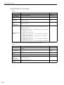
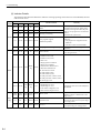
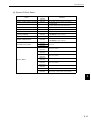
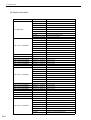
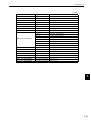
2.2 List of Modules
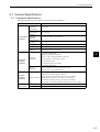
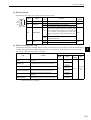
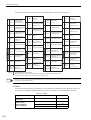
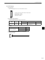
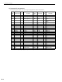
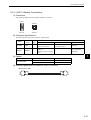
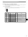
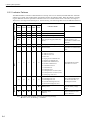
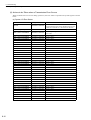
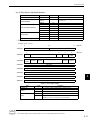
2.2.1 MP2200 Modules
The following table shows the Modules that make up MP2200 systems.
Basic Unit
Group
Base Units
CPU Modules
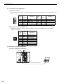
Motion
Modules
Optional Modules
I/O Modules
Communication Modules
Expansion
Interface
Modules
Type
Base Unit (for AC
power supply)
Base Unit (for DC
power supply)
CPU Module
MECHATROLINK
Interface Servo
Module
Analog Servo Interface Module
Description
Model
Occupied
slots
MBU-01
JEPMC-BU2200
−
MBU-02
JEPMC-BU2210
−
CPU-01
JAPMC-CP2200
1
MP2200 system CPU
Overview
Basic Unit with 85- to 276-VAC power supply
(9 slots)
Basic Unit with 24-VDC (±20%) power supply (9 slots)
SVB-01
JAPMC-MC2310
1
MECHATROLINK-I and
MECHATROLINK-II-compatible
SERVOPACKs (16 axes max.)
SVA-01
JAPMC-MC2300
1
Analog servo interface (2 axes)
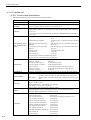
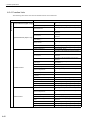
I/O Module
LIO-01
JAPMC-IO2300
1
I/O Module
LIO-02
JAPMC-IO2301
1
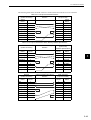
I/O Modules
Ethernet Communication Module
General-purpose
Serial Communication Module
DeviceNet Communication Module
PROFIBUS Communication Module
LIO-04
JAPMC-IO2303
1
16 inputs and 16 outputs (sink mode outputs)
1 pulse input
16 inputs and 16 outputs (source mode outputs)
1 pulse input
32 inputs and 32 outputs (sink mode outputs)
218IF-01 JAPMC-CM2300
1
RS-232C/Ethernet communication
217IF-01 JAPMC-CM2310
1
RS-232C, RS-422, and RS-485 communication
260IF-01 JAPMC-IO2320
1
RS-232C and DeviceNet communication
261IF-01 JAPMC-IO2330
1
RS-232C and PROFIBUS communication
Connection Interface
1
EXIOIF
JAPMC-EX2200
2
System bus expansion (maximum 4-Rack configuration)
2-5
2 System Configuration
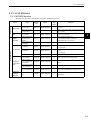
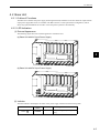
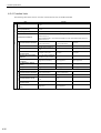
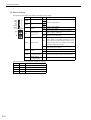
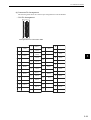
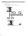
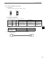
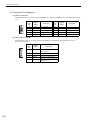
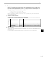
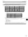
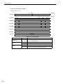
2.3 Devices Connectable to MECHATROLINK
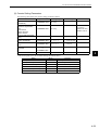
The devices that are compatible with MECHATROLINK and can be connected to the SVB-01 Module are listed
below.
(1) SERVOPACKs
The following table shows SERVOPACKs that are compatible with MECHATROLINK and can be connected to
the SVB-01 Module.
MECHATROLINK-I
MECHATROLINK-II
SGD-N
SGDB-AN
SGDH-E
JUSP-NS100
SGDH-E
JUSP-NS115
Model
MECHATROLINK-I compatible AC
SERVOPACKs
Details
{
×
Σ-II Series SGDH Servodrives NS100
MECHATROLINK-I Interface Unit
{
×
Σ-II Series SGDH Servodrives NS115
MECHATROLINK-II Interface Unit
{
{
SGDS-1
Σ-III Series AC Servodrives
{
{
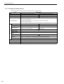
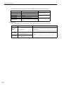
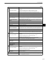
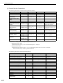
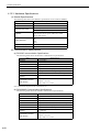
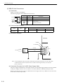
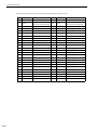
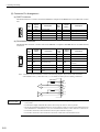
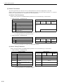
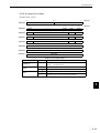
(2) I/O Modules
The following table shows Modules that are compatible with MECHATROLINK and can be connected to the
SVB-01 Module.
Model
MECHATROLINK-I MECHATROLINK-II
64-point I/O Module
24 VDC, 64 inputs, 64 outputs
{
×
DC Input Module
12/24 VDC, 16 inputs
DC Output Module
12/24 VDC, 16 outputs
{
×
{
×
AC Input Module
100 VAC, 8 inputs
AC Input Module
200 VAC, 8 inputs
AC Output Module
100/200 VAC, 8 outputs
{
×
{
×
{
×
Relay Module
Wide voltage range relay contacts, 8 outputs
A/D Module
Analog inputs, −10 to 10 V, 4 channels
D/A Module
Analog outputs, −10 to 10 V, 2 channels
{
×
{
×
{
×
Counter Module
Reversible counter, 2 channels
Pulse Output Module
Pulse output, 2 channels
64-point I/O Module
24 VDC, 64 inputs, 64 outputs
{
×
{
×
{
{
Counter Module
Reversible counter, 2 channels
Pulse Output Module
Pulse output, 2 channels
A/D Module
Analog inputs, −10 to 10 V, 4 channels
D/A Module
Analog outputs, −10 to 10 V, 2 channels
{
{
{
{
{
{
{
{
JAPMC-MC2310
SVB-01 Motion Module
JEVSA-YV250
MYVIS YV250 Machine Vision System
{
{
{
{
JEPMC-MC400
MP940 Motion Controller
{
×
JEPMC-IO350
JAMSC-120DDI34330
JAMSC-120DDO34340
JAMSC-120DAI53330
JAMSC-120DAI73330
JAMSC-120DAO83330
JAMSC-120DRA83030
JAMSC-120AVI02030
JAMSC-120AVO01030
JAMSC-120EHC21140
JAMSC-120MMB20230
JEPMC-IO2310
JEPMC-PL2900
JEPMC-PL2910
JEPMC-AN2900
JEPMC-AN2910
2-6
Details
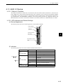
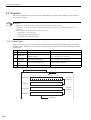
2.4 Cables and Accessories
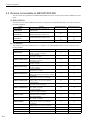
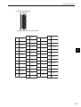
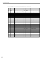
2.4 Cables and Accessories
2.4.1 Cables
The following table shows the cables that can be connected to the MP2200.
Module
SVB-01
Connector
M-I/II
Details
MECHATROLINK-I
and
MECHATROLINK-II
Cables
Model
JEPMC-W6002-
JEPMC-W6003-
JEPMC-W6010-
JEPMC-W6022
SVA-01
CH1,CH2
SGDS Cable
JEPMC-W2040-
LIO-01
LIO-02
I/O
External I/O Cable
JEPMC-W2061-
LIO-04
CN1,CN2
External I/O Cable
JEPMC-W6060-
Communication
Modules
PORT
RS-232C Cable
218IF-01
10Base-T
Ethernet Cable
JEPMC-W5310-
JEPMC-W5311-
RS-422/485
RS-422 and RS-485
Cable
260IF-01
DeviceNet
DeviceNet Cable
261IF-01
PROFIBUS
PROFIBUS Cable
EXIOIF
CN1IN,
CN2OUT
EXIOIF Cable
Between LIO-01 or LIO-02 and external
I/O
Between LIO-04 and external I/O
Between RS-232C port and 25-pin, D-sub
connector (male)
Between RS-232C port and DOS
Cross cable (Category 3 min.)
10314-52A0-008
MSTB2-5/5-GF5.08AM
17LE-1309027(D33C)
JEPMC-W2091-
Between EXIOIF and EXIOIF
10114-3000VE
2
Terminator
• Between SVA-01 and SGDS1
Module-side connector (manufactured by
3M)
Cable-side connector (manufactured by
3M)
Shell (manufactured by 3M)
Module-side connector (manufactured by
Phoenix Contact)
Module-side connector (manufactured by
Daiichi Denshi Kogyo)
1010214-52A2JL
217IF-01
Specifications
• Between SVB-01 and I/O Unit
• Between SVB-01 and SGDHE+NS100
• Between SVB-01 and SGDHE+NS115
• Between SVB-01 and SGDS1
With USB connector on both ends*
Note: The JEPMC-W6003- has a ferrite core.
• Between SVB-01 and SGD-N
• Between SVB-01 and SGDB-AN
• Between USB connector and loose
wires
* Commercially-available USB cables cannot be used. Always use Yaskawa cables.
2.4.2 Accessories
Name
DIN Rail Mounting Clips
Battery
Power Supply Connector
Model
JEPMC-OP300
JZSP-BA01
721-863/001-034
721-863/001-000
Remarks
−
ER3VC + Special Connector (BA000517)
MBU-01 Unit Cable side (manufactured by WAGO, black)
MBU-02 Unit Cable side (manufactured by WAGO, white)
2-7
2 System Configuration
2.5.1 Software for Programming Devices
2.5 Software
2.5.1 Software for Programming Devices
Name
MPE720
Model
CPMC-MPE720 (Ver. 5.10 or later)* CD-ROM (1 disk)
* Older versions cannot be used. Always use Ver. 5.10 or later.
2-8
Remarks
3
System Startup
This chapter describes the startup procedure for the MP2200 system and provides sample programs for typical operation and control.
3
3.1 Outline - - - - - - - - - - - - - - - - - - - - - - - - - - - - - - - - - - - - - - - - - - - - - - - - - 3-2
3.1.1 System Startup Flowchart - - - - - - - - - - - - - - - - - - - - - - - - - - - - - - - - - - - - - - - - - - - - 3-2
3.1.2 System Configuration - - - - - - - - - - - - - - - - - - - - - - - - - - - - - - - - - - - - - - - - - - - - - - 3-3
3.1.3 Device Preparation - - - - - - - - - - - - - - - - - - - - - - - - - - - - - - - - - - - - - - - - - - - - - - - - 3-4
3.1.4 Connecting and Wiring the System - - - - - - - - - - - - - - - - - - - - - - - - - - - - - - - - - - - - - 3-6
3.1.5 Initializing the System - - - - - - - - - - - - - - - - - - - - - - - - - - - - - - - - - - - - - - - - - - - - - - 3-8
3.1.6 Starting the MPE720 - - - - - - - - - - - - - - - - - - - - - - - - - - - - - - - - - - - - - - - - - - - - - - 3-11
3.2 Sample Program 1: Manual Operation - - - - - - - - - - - - - - - - - - - - - - - - - 3-36
3.2.1 Description - - - - - - - - - - - - - - - - - - - - - - - - - - - - - - - - - - - - - - - - - - - - - - - - - - - - - 3-36
3.2.2 Operation - - - - - - - - - - - - - - - - - - - - - - - - - - - - - - - - - - - - - - - - - - - - - - - - - - - - - - 3-37
3.2.3 Program Details - - - - - - - - - - - - - - - - - - - - - - - - - - - - - - - - - - - - - - - - - - - - - - - - - 3-40
3.3 Sample Program 2: Positioning Control - - - - - - - - - - - - - - - - - - - - - - - - 3-47
3.3.1 Description - - - - - - - - - - - - - - - - - - - - - - - - - - - - - - - - - - - - - - - - - - - - - - - - - - - - - 3-47
3.3.2 Operation - - - - - - - - - - - - - - - - - - - - - - - - - - - - - - - - - - - - - - - - - - - - - - - - - - - - - - 3-48
3.3.3 Program Details - - - - - - - - - - - - - - - - - - - - - - - - - - - - - - - - - - - - - - - - - - - - - - - - - 3-50
3.4 Sample Program 3: Phase Control with an Electronic Shaft - - - - - - - - - - 3-52
3.4.1 Description - - - - - - - - - - - - - - - - - - - - - - - - - - - - - - - - - - - - - - - - - - - - - - - - - - - - - 3-52
3.4.2 Operation - - - - - - - - - - - - - - - - - - - - - - - - - - - - - - - - - - - - - - - - - - - - - - - - - - - - - - 3-53
3.4.3 Program Details - - - - - - - - - - - - - - - - - - - - - - - - - - - - - - - - - - - - - - - - - - - - - - - - - 3-55
3.5 Sample Program 4: Phase Control with an Electronic Cam - - - - - - - - - - - 3-57
3.5.1 Description - - - - - - - - - - - - - - - - - - - - - - - - - - - - - - - - - - - - - - - - - - - - - - - - - - - - - 3-57
3.5.2 Operation - - - - - - - - - - - - - - - - - - - - - - - - - - - - - - - - - - - - - - - - - - - - - - - - - - - - - - 3-58
3.5.3 Program Details - - - - - - - - - - - - - - - - - - - - - - - - - - - - - - - - - - - - - - - - - - - - - - - - - 3-60
3-1
3 System Startup
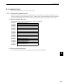
3.1.1 System Startup Flowchart
3.1 Outline
This section explains the system startup procedure when the sample program on the MPE720 installation disk is
used. Details on the machine system design have been omitted here.
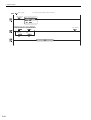
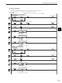
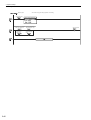
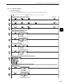
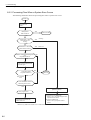
3.1.1 System Startup Flowchart
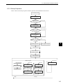
The system startup procedure is outlined below.
Refer to the references given in the right-hand column for information on each step.
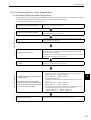
1. Prepare the equipment needed for testing.
3.1.3 Device Preparation
2. Mount the 218IF-01 to the MP2200.
Chapter 5 Mounting and Wiring
3.
Connect the MPE720, and wire the Servomotors
and SERVOPACKs.
4. Initialize the SERVOPACKs.
3.1.5 Initializing the System
5.
The connected devices are automatically confirmed.
3.1.5 Initializing the System
6.
Install the sample programs and start the
MPE720.
3.1.6 Starting the MPE720
7.
Save the sample program and configuration defi3.1.6 Starting the MPE720
nitions to flash memory.
8.
3-2
3.1.4 Connecting and Wiring the System
Execute the program and check the test operation.
3.2 Sample Program 1: Manual Operation
3.3 Sample Program 2: Positioning Control
3.4 Sample Program 3: Phase Control with an
Electronic Shaft
3.5 Sample Program 4: Phase Control with an
Electronic Cam
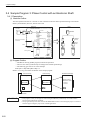
3.1 Outline
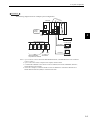
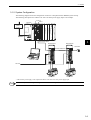
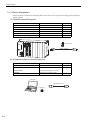
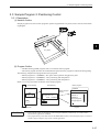
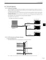
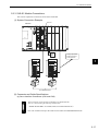
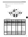
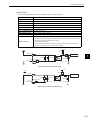
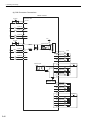
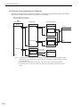
3.1.2 System Configuration
The following diagram shows the configuration of devices to help describe the MP2200 system startup.
The following description uses a Basic Unit with a 24-VDC power supply input as an example.
218IF-01
SVB-01
MP2200
MP2200 MBU-02 CPU-01 218IF-01 SVB-01
LIO-01
10Base-T
DC
Optional Module
CN1
Optional Module
BATTEY
Optional Module
I/O
PORT
Optional Module
POWER
Optional Module
24-VDC
power
supply
CN2
POWER
3
MECHATROLINK-II
SERVOPACK
YASKAWA SERVOPACK
SERVOPACK
200V
YASKAWA SERVOPACK
SGDS-01A12A
SW1
CHARGE
C
N
6
A/B
SW1
JEPMC-W6002-01
L1
L2C
MPE720
L1C
L2C
C
N
3
B1/
B2
V
A/B
L2
C
N
3
B1/
U
CHARGE
Terminator
C
N
6
L1
L2
L1C
200V
SGDS-01A12A
B2
C
N
1
W
U
V
C
N
1
W
C
N
2
C
N
2
C
N
4
C
N
4
200 VAC
Servomotor
Servomotor
* The 24-VDC power supply is not required for a Basic Unit with a 100-VAC power supply input.
INFO
Refer to Chapter 5 Mounting and Wiring for information on mounting Modules.
3-3
3 System Startup
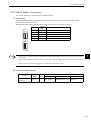
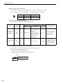
3.1.3 Device Preparation
3.1.3 Device Preparation
Prepare the devices shown in the following tables. These devices are required for checking operation using the
sample program.
(1) Controller-related Equipment
Name
Base Unit
CPU-01 Module
218IF-01
SVB-01 Module
MECHATROLINK Cable (1 mÅj
Terminator
Model
JEPMC-BU2210 or JEPMC-BU2200
JAPMC-CP2200
JAPMC-CM2300
JAPMC-MC2310
JEPMC-W6002-01
JEPMC-W6022
Quantity
1
1
1
1
2
1
MP2200 MBU-02 CPU-01 218IF-01 SVB-01
POWER
JEPMC-W6022
JEPMC-W6002-01
DC
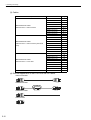
(2) Programming Device-related Equipment
Name
Model
CPMC-MPE720
JEPMC-W5311-03
MPE720
RS-232C Cable
or
Ethernet Cable
Computer
Quantity
1
1
Commercially available cross cable
Commercially available product
Note: The MP2200 can be connected via RS-232C or Ethernet connections.
Computer
JEPMC-W5311-03
MPE720
3-4
1
3.1 Outline
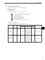
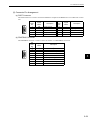
(3) Servodrive-related Equipment
Name
Σ-III SERVOPACKs
Σ-III Servomotors
Motor Cables (3 m)
Encoder Cables (3 m)
Digital Operator
Model
SGDS-01A12A
SGMAS-01ACA21
JZSP-CSM01-03
JZSP-CSP01-03
JUSP-OP05A
Quantity
2
2
2
2
1
1 12
COIN
VCMP
SVON
TGON
REF
CHARGE
3
YASKAWA
ALARM
RESET
SCROLL
MODE/SET
JOG
SVON
READ
DATA
WRITE
SERVO
SERVO
DIGITAL OPERATOR JUSP-OP05A
SERVOPACK
Servomotor
Digital Operator
(4) Other Required Equipment
Name
24-VDC power supply
Specifications
Current capacity of 2 A or greater
Quantity
1
3-5
3 System Startup
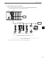
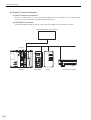
3.1.4 Connecting and Wiring the System
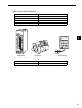
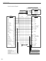
3.1.4 Connecting and Wiring the System
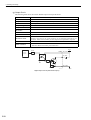
(1) Connecting the MPE720 and MP2200
The following figure shows how to connect the MPE720 and the 218IF-01 Module using a PP Cable.
218IF-01
MP2200
MP2200 MBU-02 CPU-01 218IF-01 SVB-01
10Base-T
DC
Optional Module
Optional Module
Optional Module
CN1
Optional Module
M- /
BATTEY
Optional Module
PORT
Optional Module
POWER
CN2
POWER
JEPMC-W5311-03
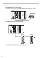
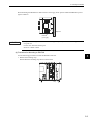
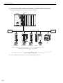
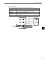
(2) Connecting the MP2200 and SERVOPACKs
Use a MECHATROLINK Cable to connect the MP2200 and SERVOPACKs.
SVB-01
MP2200
MP2200 MBU-02 CPU-01 218IF-01 SVB-01
POWER
Optional Module
Optional Module
Optional Module
10Base-T
DC
Optional Module
CN1
Optional Module
M- /
BATTEY
Optional Module
PORT
CN2
POWER
SERVOPACK
YASKAWA SERVOPACK
SERVOPACK
200V
YASKAWA SERVOPACK
SGDS-02A12A
SW1
MECHATROLINK-II
CHARGE
C
N
6
A/B
SW1
JEPMC-W6002-01
L1
L2
L1C
L2C
L2
L1C
L2C
C
N
3
B2
C
N
1
W
U
V
C
N
1
W
C
N
2
C
N
2
C
N
4
C
N
4
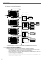
Set the SERVOPACK MECHATROLINK station numbers to 1 and 2.
The sample program is designed to operate with station numbers 1 and 2.
3-6
C
N
6
A/B
B1/
B2
V
CHARGE
L1
C
N
3
B1/
U
200V
SGDS-02A12A
Terminator
3.1 Outline
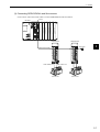
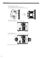
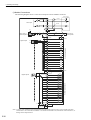
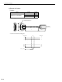
(3) Connecting SERVOPACKs and Servomotors
Use the motor cable and encoder cable to connect SERVOPACKs and Servomotors.
SVB-01
MP2200
MP2200 MBU-02 CPU-01 218IF-01 SVB-01
POWER
10Base-T
DC
Optional Module
Optional Module
Optional Module
Optional Module
CN1
Optional Module
M- /
BATTEY
Optional Module
PORT
CN2
POWER
SERVOPACK
YASKAWA SERVOPACK
SERVOPACK
200V
YASKAWA SERVOPACK
SGDS-02A12A
SW1
MECHATROLINK-II
CHARGE
C
N
6
L2C
C
N
3
Terminator
3
L2
L1C
L2C
C
N
3
B2
C
N
1
W
JZSP-CSM01-03
C
N
6
A/B
B1/
B2
V
CHARGE
L1
B1/
U
SW1
A/B
L1
L2
L1C
200V
SGDS-02A12A
U
V
C
N
1
W
C
N
2
C
N
2
C
N
4
C
N
4
JZSP-CSP01-03
Servomotor
Servomotor
3-7
3 System Startup
3.1.5 Initializing the System
3.1.5 Initializing the System
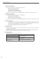
This section describes the Σ-III SERVOPACK initialization and self-configuration procedures required when
first starting a MP2200 system.
(1) Initializing Σ-III SERVOPACKs
This section explains the procedure for initializing the SERVOPACKs. Always initialize SERVOPACKs that
have been brought from other systems. This initialization procedure is not required for SERVOPACKs that have
not been used before.
1. Turn ON SERVOPACK.
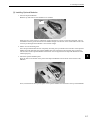
Turn ON the control power supply and main power supply for the SERVOPACK.
2. Initialize parameter settings.
Return the parameter settings to the standard default settings using Fn005.
3. Disconnect SERVOPACK power.
Turn OFF the control and main power supplies.
4. Turn ON SERVOPACK.
Turn ON the control power supply and main power supply for the SERVOPACK.
The method for initializing the parameter settings (step 2, above) from the SERVOPACK Digital Operator is
shown below.
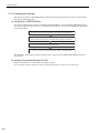
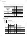
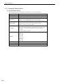
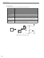
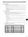
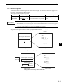
(2) Initializing Parameter Settings (Fn005)
Initialize the parameters to return them to the default settings.
Note: The settings cannot be initialized if writing is prohibited using Fn010 or if the Servo ON signal is ON.
3-8
3.1 Outline
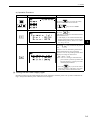
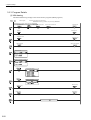
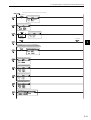
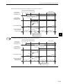
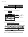
(a) Operation Procedure
Operation Keys
Display Example
Description
Press the
Key to display the Utility
Function Mode main menu. Press the
Keys to select Fn005.
Press the
Key.
The display is switched to the Fn005 Parameter
Initialization Screen.
• If the display is not switched and NO-OP is
displayed in the status display, the Write Prohibited Setting (Fn010 = 0001) is set. Check
the setting and reset.
3
Press the
Key to initialize the parameters.
Parameter Init will blink during initialization.
When initialization has been completed,
Parameter Init will stop blinking and the status
display will change as shown below.
BB → Done → A.941
Note: A.941 is a warning to indicate that the
power must be cycled for a parameter that
has been changed. Cycle the power after
initializing the parameters.
• Press the
Key if you do not want to
initialize parameters. The display will return
to the Utility Function Mode main menu.
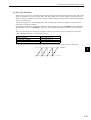
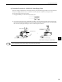
(3) Turning ON the Power Supply Again
Parameter settings will be initialized but some of the parameters need the power to be cycled to enable the settings. Always turn OFF the power and then turn it ON again.
3-9
3 System Startup
3.1.5 Initializing the System
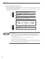
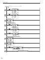
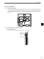
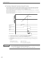
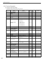
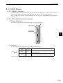
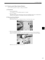
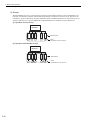
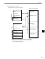
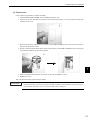
(4) Executing MP2200 Self-configuration
Execute self-configuration to automatically configure the Optional Modules mounted to the Basic Unit and the
devices connected to the MECHATROLINK.
This section explains the method for executing self-configuration. The power to Σ-III SERVOPACKs has already
been turned ON prior in this procedure.
1. Turn OFF the power.
Turn OFF the Basic Unit 24-VDC power supply.
STOP
SUP
INIT
CNFG
MON
TEST
OFF
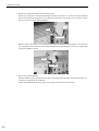
2. Set DIP switches.
Turn ON the INIT and CNFG pins on the DIP switch (SW1) on the
Basic Unit.
SW1
ON
3. Turn ON the power.
Turn ON the Basic Unit 24-VDC power supply.
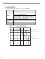
4. Check the display.
Check that the LED indicators on the Basic Unit change as shown
below.
RDY
RUN
RDY
RUN
RDY
RUN
ALM
ALM
ALM
ERR
ERR
ERR
TX
BAT
TX
BAT
TX
BAT
Not lit
STOP
SUP
INIT
CNFG
MON
TEST
OFF
IMPORTANT
Lit
Flashing
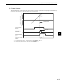
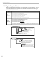
5. Reset DIP switch.
Turn OFF the INIT and CNFG pins on the DIP switch (SW1) on the
Basic Unit.
SW1
ON
• INIT Switch
RAM data will be cleared if the INIT pin on the DIP switch on the CPU Module is turned ON and the
power is turned ON. Flash memory data is read when the INIT switch is turned OFF and the power is
turned ON. Therefore, always save data to the MP2200 flash memory before turning OFF the power when
writing or editing programs.
Refer to 3.1.6 Starting the MPE720 for information on saving data to flash memory.
• Turning OFF Power after Executing Self-configuration
Do not turn OFF the 24-V power supply to the MP2200 after executing self-configuration until the definitions data has been saved to flash memory in the MP2200. If the power is turned OFF somehow before the
data is saved to flash memory, execute self-configuration again.
3-10
3.1 Outline
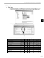
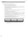
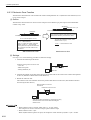
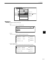
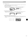
3.1.6 Starting the MPE720
This section describes the preparations for connecting the MPE720 to the MP2200, and the method for installing
the sample program for the MP2200.
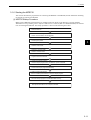
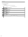
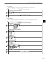
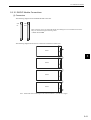
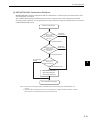
(1) MPE720 Startup Procedure
Make sure the MPE720 System Software is installed in advance. Refer to the Machine Controller MP900/
MP2000 Series Programming Device Software MPE720 User’s Manual (Ref. No. SIEPC88070005) for information on installing the MPE720. The startup procedure is shown in the following flow-chart.
1. Starting the MPE720
Start the MPE720.
2. Communication settings
Define communications with the MP2200.
3. Creating group folders
Create a group folder.
3
4. Creating an order folder
Create an order folder.
5. Creating a controller folder
Create a controller folder.
6. Logging on online
Log on online to the MP2200.
7. Loading the sample programs
Load the sample programs from the MPE720 system CD-ROM.
8. Transferring individual sample programs
Transfer the sample programs individually.
9. Setting individual parameters
Set the individual parameters to match the sample program.
10. Saving to flash memory
Save the sample program to the MP2200 flash memory.
11. All program file dump
Back up MP2200 data on the computer hard disk.
3-11
3 System Startup
3.1.6 Starting the MPE720
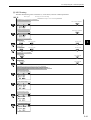
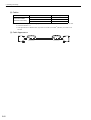
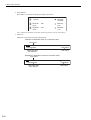
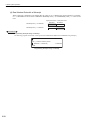
(2) Starting the MPE720
Start the MPE720 using the procedure below.
1. Double-click the MPE720 icon in the YE_Applications Folder.
Double-click
2. The File Manager Window will be displayed.
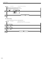
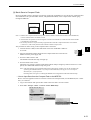
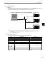
(3) Communication Settings
Make communication settings for connecting the MPE720 and the MP2200 using the procedure below. These
settings are not required if the communication settings have already been made.
1. When the MPE720 is started, the File Manager and Communication Process Button will be displayed on
the Toolbar at the bottom of the screen. Click the Communication Process button to open the Communication Process Window.
Click
3-12
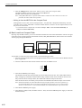
3.1 Outline
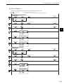
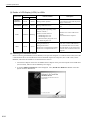
2. Double-click Logical PT number 1 in the Communication Process Window to display the Logical Port
Setting Window.
Double-click
3. For RS-232C connections, select Port Kind - Serial in the Logical Port Setting Window.
3
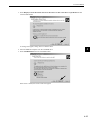
4. Setting Serial Communication Ports
a) Click the Detail button in the Logical Port Setting Window.
3-13
3 System Startup
3.1.6 Starting the MPE720
b) The Serial Port Setting Window will be displayed. Match the settings under Physical Port to the computer’s serial communication port. Leave the other items on the default settings. Once the settings have
been completed and checked, click the OK button.
c) The Logical Port Setting Window will be displayed. Click the OK button again. The screen will return
to the Communication Process Window. Check that Serial has been allocated to the Logical PT number
1.
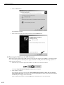
5. Ethernet Connections
Double-click Logical PT number 2 in the Communication Process Window to display the Logical Port
Setting Window.
Double-click
3-14
3.1 Outline
6. Ethernet Settings
a) Select Port Kind - CP-218 in the Logical Port Setting Window and click the Detail button.
b) The CP-218 Port Setting Window will be displayed. Select OFF for Default and enter the computer IP
address in the IP Address (First) field. Leave the other items on the default settings. Once the settings
have been completed and checked, click the OK button.
3
c) The Logical Port Setting Window will be displayed. Click the OK button again. The screen will return
to the Communication Process Window. Check that CP-218 has been allocated to the Logical PT number 2.
3-15
3 System Startup
3.1.6 Starting the MPE720
7. Saving Communication Port Settings
Save the communication port settings. These settings will be used as the communication port information
whenever the communication process is started. The procedure for saving the communication port settings is shown below.
a) Click File - Save.
b) A save confirmation window will be displayed. Click the Yes button.
8. Starting the Communication Process Again
The communication process must be started again when settings have been made or changed.
a) Select File - Exit to close the Communication Process Window.
b) A confirmation message will be displayed. Click the Yes button.
c) Double-click the Communication Manager Icon in the YE_Applications Folder to reopen the Communication Process Window.
Double-click
3-16
3.1 Outline
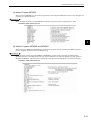
(4) Creating Group Folders
Create a group folder in the File Manager Window, using the procedure below.
Example: Folder name: MP2200
Create a group folder using the procedure below.
1. Right-click the root directory and select New - Group folder.
2. Enter the group folder name in the Make New Folder Window and click the OK button. The group folder
name must be 8 characters or less.
3
3. The new group folder MP2200 will be created. Double-click the root directory or click the
display the MP2200 Group Folder.
button to
3-17
3 System Startup
3.1.6 Starting the MPE720
(5) Creating an Order Folder
Create an order folder using the procedure below.
Example: Folder name: YESAMPLE
1. Right-click the MP2200 Group Folder and select New - Order Folder.
2. Enter the order folder name in the Make New Folder Window and click the OK button. The order folder
name must be 8 characters or less.
3. The new “YESAMPLE” Order Folder will be created. Double-click the MP2200 Group Folder or click
the
button to display the YESAMPLE order folder.
(6) Creating a Controller Folder
Register the new controller to be used to create the program using the procedure below.
Controller name: 2200SMPL
Controller type: MP2200
Create a controller folder using the procedure below.
1. Right-click the YESAMPLE Order Folder and select Create New Folder - Controller Folder.
3-18
3.1 Outline
2. Set the Controller Name and Controller Type shown below, and click the OK button.
Controller name: 2200SMPL
Controller type: MP2200
3
3. A new controller folder 2200SMPL will be created. Double-click the YESAMPLE Order Folder or click
the
button to display the 2200SMPL Controller Folder.
(7) Logging On Online
Log on online to the MP2200 using the procedure outlined below.
1. Right-click the 2200SMPL Controller Folder and select Online. The mode will change from offline to
online.
3-19
3 System Startup
3.1.6 Starting the MPE720
2. Right-click the 2200SMPL Controller Folder and check that there is a check mark next to Online. Also
check that Online at the bottom right of the screen is listed as Connected, then select Properties.
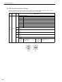
3. The Controller Configuration Window will be opened. Select the Network Tab. Online should be set to
Yes.
Under Logical Port Number (Device Type), select the same Logical PT that was set for the communication process.
Note: CP-217: RS-232C connection
CP-218: Ethernet connection
3-20
3.1 Outline
4. For RS-232C connections, leave all settings other than Logical Port Number (Device Type) on the default
settings.
3
5. For Ethernet connections, make the settings shown below.
6. A confirmation message will be displayed. Click the Yes button.
3-21
3 System Startup
3.1.6 Starting the MPE720
7. Logging On Online
a) Right-click the 2200SMPL Controller Folder and select Log On.
b) Input the user name USER-A and the password USER-A and click the OK button.
3-22
3.1 Outline
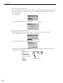
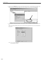
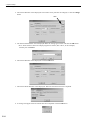
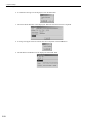
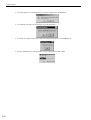
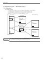
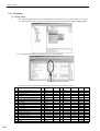
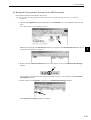
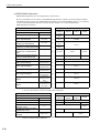
(8) Loading the Sample Programs
Load the sample programs on the MPE720 system CD-ROM using the procedure below. Insert MPE720 system
CD-ROM into the computer CD-ROM drive.
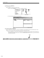
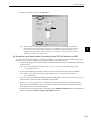
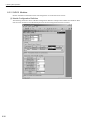
1. Double-click the 2200 SMPL-E.EXE file in the SAMPLE Folder on the CD-ROM.
Double-click
2. The window for specifying the destination of the file will be displayed. Specify the destination of the file
and click the Decompress button.
3
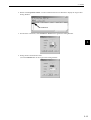
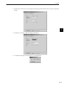
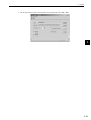
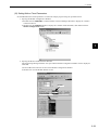
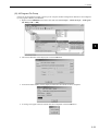
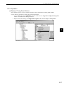
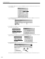
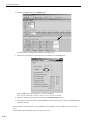
3. Right-click the 2200SMPL Controller Folder and select File Transfer - All File Transfer - All Program
File Transfer (Other Media - HD).
3-23
3 System Startup
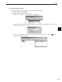
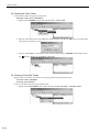
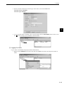
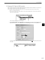
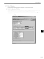
3.1.6 Starting the MPE720
4. The Execute Window will be displayed. The transfer source path must be changed, so click the Change
button.
Click
5. The Transfer Path Window will be displayed. Make the settings given below and click the OK button.
Drive: Select the drive where the sample program was stored. (The A drive, in this example.)
Transfer path: 2200SMPL
6. The Execute Window will be displayed. Click the OK button.
7. The Execute Status Window will be displayed. Wait until the transfer has been completed.
8. A message will appear when the transfer has been completed. Click the OK button.
3-24
3.1 Outline
9. The All File Transfer Disk to Disk Window will be displayed. Select File - Exit.
3
3-25
3 System Startup
3.1.6 Starting the MPE720
(9) Individual Loading of Sample Programs
Transfer sample programs to the MP2200 individually using the procedure below.
1. Right-click the 2200SMPL Controller Folder and select File Transfer - Individual File Transfer - Individual Program File Load (HD → CPU).
2. The Individual Load Window will be displayed. Select the following transfer items:
•
•
•
•
3-26
DWG
Scan Time
Data Trace
Motion Main Program
3.1 Outline
3. Click the Details button to the right of DWG to display the DWG Detail Data Set Window. Select Select
All and click the OK button.
3
4. Click the Details button to the right of Motion Main Program to display the Motion Main Program Detail
Set Window. Select Select All and click the OK button.
5. The Individual Load Window will be displayed. Select File - Execute.
3-27
3 System Startup
3.1.6 Starting the MPE720
6. A confirmation message will be displayed. Click the Yes button.
7. The Execute Status Window will be displayed. Wait until the transfer has been completed.
8. A message will appear when the transfer has been completed. Click the OK button.
9. The Individual Load Window will be displayed. Select File - Exit.
3-28
3.1 Outline
(10) Setting Motion Fixed Parameters
Set the MP2200 motion fixed parameters to match the sample program using the procedure below.
1. Opening the Module Configuration Window.
a) Double-click the 2200SMPL Controller Folder in the File Manager Window to display the 5 folders
contained within it.
b) Double-click the Definition Folder to display the 6 folders inside that folder, then double-click the
Module Configuration Folder.
3
2. Opening the Motion Fixed Parameter Window.
The Engineering Manager Window will open and the Module Configuration Window will be displayed
inside that.
a) Point to 02 in the Controller section of the Module Configuration Window.
b) Double-click 1 in the Module Details section.
a) Point
b) Double-click
3-29
3 System Startup
3.1.6 Starting the MPE720
3. Setting the Fixed Parameters for Axis 1
Display the SVB Definition Window in the Engineering Manager Window. Check that the Fixed Parameters Tab Page has been selected.
a) Select Axis 1 from the list of axes at the top left of the SVB Definition Window.
b) Select mm as the Reference Unit for parameter 4 on the Fixed Parameters Tab Page.
a) Select
b) Set reference unit selection
4. Saving Fixed Parameter Settings
Select File - Save in the Engineering Manager Window.
5. Setting and Saving Axis 2 Fixed Parameters
Referring to steps 3 and 4 in this procedure, select Axis 2 and make the settings the same way as for axis
1.
3-30
3.1 Outline
6. Closing the Engineering Manager Window
Select File - Exit in the Engineering Manager Window.
(11) Saving to Flash Memory
Save sample programs that have been transferred individually to the MP2200 to the MP2200 flash memory using
the procedure below.
1. Right-click the 2200SMPL Controller Folder and select File Transfer - Other - Flash Save.
3
2. The Save Flash Memory Content Window will be displayed. Select File - Execute.
3-31
3 System Startup
3.1.6 Starting the MPE720
3. A message appears to confirm that the CPU will be stopped. Click the Yes Button.
4. A confirmation message will be displayed. Click the Yes button.
5. A message will appear when the save has been completed normally. Click the OK button.
6. The Save Flash Memory Content Window will be displayed. Select File - Exit.
3-32
3.1 Outline
(12) All Program File Dump
Execute an All Program File Dump to back up to the computer module configuration definitions self-configured
by and programs edited by the MP2200.
1. Right-click the 2200SMPL Controller Folder and select File Transfer - All File Transfer - All Program
File Dump (CPU → HD).
3
2. The Execute Window will be displayed. Click the OK button.
3. An Execute Status Window will be displayed. Wait until the transfer has been completed.
4. A message will appear when the transfer has been completed. Click the OK button.
3-33
3 System Startup
3.1.6 Starting the MPE720
5. The All Dump Window will be displayed. Select File - Exit.
(13) CPU RUN Settings
The procedure for starting the CPU, which was set to STOP during the flash save process, is explained below.
1. Right-click the 2200SMPL Controller Folder and select CPU Control.
2. The Controller Running Status Window will be displayed. Click the RUN button.
3-34
3.1 Outline
3. A confirmation message will be displayed. Click the Yes button. Check that the RUN LED indicator on
the CPU Module is lit.
4. The Controller Running Status Window will be displayed again. Click the Close button.
(14) Logging Off
Log off when you have finished with the MPE720 using the procedure below.
3
1. Right-click the 2200SMPL Controller Folder and select Log Off.
2. A confirmation message will be displayed. Click the Yes button.
3-35
3 System Startup
3.2.1 Description
3.2 Sample Program 1: Manual Operation
3.2.1 Description
(1) Program Outline
•
•
•
•
The H01 drawing (ladder program) turns ON the servo, resets alarms, and sets parameters.
The H02.01 drawing (ladder program) controls jog and step operation for axis 1.
The H02.02 drawing (ladder program) controls jog and step operation for axis 2.
Refer to 3.2.3 Program Details for details on the sample program.
Parent Drawings
H Drawing
SEE
Name H01
Child Drawings
Grandchild Drawings
H01 Drawing
• SERVO ON
• Alarm reset
• Parameter settings
END
H02.01 Drawing
Axis 1
• Jog operation
• Step operation
H02 Drawing
SEE
Name H02
SEE
Name H02.01
SEE
Name H02.02
END
END
High-speed scan
IMPORTANT
3-36
END
H02.02 Drawing
Axis 2
• Jog operation
• Step operation
END
This sample program has no power OFF circuit for the SERVOPACK in the event of emergency stops or
overtravel. Include a proper emergency stop circuit in actual applications.
3.2 Sample Program 1: Manual Operation
3.2.2 Operation
(1) Display of Tuning Panel Window
In this sample program, run, stop, and other operations can be checked from a Tuning Panel Window.
Use the following procedure to display the Tuning Panel Window.
1. Log on online and open the 2200SMPL Controller Folder, then the Programs and High Scan Programs
folders in the MPE720 File Manager Window.
2. Right-click the H02 drawing in the High Scan Programs Folder and select Open - Tuning Panel.
3
3-37
3 System Startup
3.2.2 Operation
3. The Tuning Panel Window for the H02 drawing will be displayed.
Input position and current value.
The details on the Tuning Panel Window display are shown in the following table.
3-38
Display
Definition
Current Value
***************Common monitor***************
XXXXX
00000
2
Axis 1 operation ready
ON/OFF
OFF
3
Axis 2 operation ready
ON/OFF
OFF
4
Axis 1 current position
XXXXXXXXXX
0000000000
No.
Data Name
1
S
Units
Lower Limit
Upper Limit
REG-No.
DWG
00000
32767
DW00010
L
IB80000
IB80000
−0214783648
2147483647
IL8016
5
Axis 2 current position
XXXXXXXXXX
0000000000
−0214783648
2147483647
IL8096
6
***************Common operation***************
XXXXX
00000
00000
32767
DW00010
7
Servo ON PB
S
ON/OFF
OFF
8
Alarm reset PB
S
ON/OFF
OFF
9
************Manual operation and setting************
XXXXX
00000
10
Axis 1 Forward Jog
S
ON/OFF
OFF
DB000010
H02.01
11
Axis 1 Reverse Jog
S
ON/OFF
OFF
DB000011
H02.01
L
MB300000
MB300001
00000
32767
DW00010
L
12
Axis 2 Forward Jog
S
ON/OFF
OFF
DB000010
H02.02
13
Axis 2 Reverse Jog
S
ON/OFF
OFF
DB000011
H02.02
14
Axis 1 Forward Step
S
ON/OFF
OFF
DB000012
H02.01
15
Axis 1 Reverse Step
S
ON/OFF
OFF
DB000013
H02.01
16
Axis 2 Forward Step
S
ON/OFF
OFF
DB000012
H02.02
17
Axis 2 Reverse Step
S
ON/OFF
OFF
DB000013
H02.02
18
Axis 1 Step Moving Amount
S
XXXXXXXXXX
0000000000
−0214783648
2147483647
DL00010
H02.01
19
Axis 2 Step Moving Amount
S
XXXXXXXXXX
0000000000
−0214783648
2147483647
DL00010
H02.02
3.2 Sample Program 1: Manual Operation
(2) Confirming Operation
Use the following procedure to confirm operation.
Turn ON the Servo.
Start jog or step operation.
Confirm operation.
The following table gives an outline of the operation when the Tuning Panel window is used.
Data Name
Tuning Panel Operation
Current value OFF → ON
Servo ON PB
Current value ON → OFF
Current value OFF → ON
Axis 1 Forward Jog
Current value ON → OFF
Current value OFF → ON
Axis 1 Reverse
Jog
Current value ON → OFF
Current value OFF → ON
Axis 2 Forward Jog
Current value ON → OFF
Current value OFF → ON
Axis 2 Reverse
Jog
Current value ON → OFF
Enter any value.
Sets the Step moving amount for axis 1.
Enter any value.
Sets the Step moving amount for axis 2.
Axis 1 Forward
Step
Current value OFF → ON
Axis 1 Reverse
Step
Current value OFF → ON
Axis 2 Forward
Step
Current value OFF → ON
Axis 2 Reverse
Step
Current value OFF → ON
Axis 1 Step Moving
Amount
Axis 2 Step Moving
Amount
INFO
Current value ON → OFF
Operation Outline
The Servomotor will turn ON and the Servo will be clamped.
Servo turned OFF.
Axis 1 rotates forward.
Axis 1 stops.
Axis 1 rotates in reverse.
Axis 1 stops.
Axis 2 rotates forward.
Axis 2 stops.
Axis 2 rotates in reverse.
Axis 2 stops.
Axis 1 starts rotating forward for the moving amount set under Axis 1
Step Moving Amount.
Axis 1 stops rotating. Input OFF after executing stepping.
Axis 1 starts rotating in reverse for the moving amount set under Axis 1
Step Moving Amount.
Axis 1 stops rotating. Input OFF after executing stepping.
Axis 2 starts rotating forward for the moving amount set under Axis 2
Step Moving Amount.
Axis 2 stops rotating. Input OFF after executing stepping.
Axis 2 starts rotating in reverse for the moving amount set under Axis 2
Step Moving Amount.
Axis 2 stops rotating. Input OFF after executing stepping.
Current value ON → OFF
Current value ON → OFF
Current value ON → OFF
3
Actual Application Programs
Programs must be created in actual applications to monitor and control registers that correspond to the signals and data
listed above.
The register numbers that correspond to the signals used in this sample program will be the register numbers displayed
under REG-No. next to DWG at the right of the Tuning Panel window.
3-39
3 System Startup
3.2.3 Program Details
3.2.3 Program Details
(1) H Drawing
The H parent drawing controls the overall sample program.
Main Program
High-speed Main Progra
########## High-speed main program ##########
########## Servo ON and alarm reset ##########
Servo ON and alarm reset
########## Jog and step operation ##########
Jog and step operation
########## Positioning operation ##########
Positioning operation
########## Phase control ##########
Electronic cam
3-40
3.2 Sample Program 1: Manual Operation
(2) H01 Drawing
The H01 child drawing turns ON the Servo, resets alarms, and sets common parameters.
Main Program
Processing of Common Axis Setting
########## Processing of common axis settings ##########
########## Motion command detection ##########
Axis 1 motion command 0 detection
Axis 1 motion command 0
Axis 2 motion command 0 detection
Axis 2 motion command 0
########## Servo ON ##########
Axis 1 Servo ON
Servo ON PB
Axis 1 SVC_RDY
Axis 1 SV_ON
Axis 2 SVC_RDY
Axis 2 SV_ON
3
Axis 2 Servo ON
Servo ON PB
########## Alarm reset ##########
Axis 1 alarm reset
Alarm reset PB
Axis 1 ALM_RST
Axis 2 alarm reset
Alarm reset PB
Axis 2 ALM_RST
########## Speed unit and acceleration speed unit selection ##########
Bits 0 to 3: Speed unit selection (0: Reference unit/s2 ; 1: Reference unit/min2 ; 2: %
Bits 4 to 7: Acceleration speed unit selection (0: Reference unit/s2 ; 1: ms)
Axis 1 function setting 1 (units)
Axis 1, function setting 1 workpiece
Axis 1, function setting 1
Axis 2 function setting 1 (units)
Axis 2, function setting 1 workpiece
Axis 2, function setting 1
3-41
3 System Startup
3.2.3 Program Details
Main Program
Processing of Common Axis Setting
########## Linear acceleration/deceleration setting ##########
Axis 1 and 2 linear acceleration/deceleration setting
MPM running
Linear acceleration/deceleration setting
(3) H02 Drawing
The H02 child drawing controls jog and step operation.
Main Program
Manual Operation Main Processin
########## Manual operation main processing ##########
3-42
3.2 Sample Program 1: Manual Operation
(4) H02.01 Drawing
The H02.01 grandchild drawing controls jog and step operation for axis 1.
Main Program
Axis 1 Manual (Jog and Step) Operation Processing
########## Axis 1 manual (jog and step) operation processing ##########
########## Jog and step operation ##########
Axis 1 jog operation
Axis 1 Forward Jog
Axis 1 Reverse Jog
Axis 1 Forward Jog
Axis 1 SV_ON
Axis 1 Reverse Jog
Axis 1 jog reference
Axis 1 motion command 0
Axis 1 jog reference
Axis 1 jog start
Axis 1 jog start
Axis 1 jog stop
Axis 1 motion command
Axis 1 motion command
Axis 1 SV_ON
Axis 1 step reference
Axis 1 Reverse Step
Axis 1 motion command 0
Axis 1 step reference
Axis 1 step start
3
Axis 1 speed reference setting
Axis 1 step reference
Axis 1step start
Axis 1 jog start
Axis 1 jog stop
########## Step operation ##########
Axis 1 step operation
Axis 1 Forward Step Axis 1 Reverse Step
Axis 1 Forward Step
Axis 1 jog reference
Axis 1 step start
Axis 1 step stop
Axis 1 step speed and moving amount
Axis 1 motion command
3-43
3 System Startup
3.2.3 Program Details
Main Program
Axis 1 step stop
Axis 1 Manual (Jog and Step) Operation Processing
Axis 1 motion command
########## Reverse rotation selection ##########
Axis 1 jog reference
Axis 1 step
reference
3-44
Axis 1 Reverse Jog
Axis 1 Reverse
Step
Axis 1 Reverse
3.2 Sample Program 1: Manual Operation
(5) H02.02 Drawing
The H02.02 grandchild drawing controls jog and step operation for axis 2.
Main Program
Axis 2 Manual (Jog and Step) Operation Processing
########## Axis 2 manual (jog and step) operation processing ##########
########## Jog and step operation ##########
Axis 2 jog operation
Axis 2 Forward Jog
Axis 2 Reverse Jog
Axis 2 SV_ON
Axis 2 Reverse Jog
Axis 2 Forward Jog
Axis 2 jog reference
Axis 2 motion command 0
Axis 2 jog reference
Axis 2 jog start
Axis 2 jog start
Axis 2 jog stop
Axis 2 jog start
Axis 2 jog stop
3
Axis 2 speed reference setting
Axis 2 motion command
Axis 2 motion command
########## Step operation ##########
Axis 2 step operation
Axis 2 Reverse Step
Axis 2 Forward Step
Axis 2 Forward Step
Axis 2 jog reference
Axis 2 SV_ON
Axis 2 step reference
Axis 2 Reverse Step
Axis 2 step reference
Axis 2 step start
Axis 2 step reference
Axis 2 step stop
Axis 2 step start
Axis 2 step start
Axis 2 step speed and moving amount
Axis 2 motion command
3-45
3 System Startup
3.2.3 Program Details
Main Program
Axis 2 step stop
Axis 2 Manual (Jog and Step) Operation Processing
Axis 2 motion command
########## Reverse rotation selection ##########
Axis 2 jog reference
Axis 2 step
reference
3-46
Axis 2 Reverse Jog
Axis 2 Reverse
Step
Axis 2 Reverse
3.3 Sample Program 2: Positioning Control
3.3 Sample Program 2: Positioning Control
3.3.1 Description
(1) Machine Outline
Sample program 2 will use a motion program to operate a hypothetical X-Y plotter, such as the one in the following diagram.
Servomotor
Y
X
3
X-Y plotter
(2) Program Outline
• The H04 drawing (ladder program) starts a text-format motion program.
• The motion program executes the commands and operations in the program in order from the beginning.
The following sample motion programs have been prepared.
• Motion program No. 1 (MPM001): Zero point return operation using phase-C pulse
• Motion program No. 2 (MPM002): 2-axis positioning and interpolation
• Motion program No. 3 (MPM003): 2-axis positioning and interpolation
Refer to 3.3.3 Program Details for details on the sample program.
Parent drawing
Child drawing
H drawing
Motion program
H04 drawing
MPM003
Motion program
startup
SEE
Name H04
END
High-speed scan
IMPORTANT
MSEE
Program No. 001
Data DA00020
END
MPM002
MPM001
0W803C=3;
0W80BC=3;
VEL[X]100[Y]100;
ACC[X]100[Y]100;
Text-format
program
• This program is solely for the purpose of describing the MP2200 system startup. Care must be taken
because actual applications will differ.
• This program has no power OFF circuit for the SERVOPACK in the event of emergency stops or overtravel.
Include a proper emergency stop circuit in actual applications.
3-47
3 System Startup
3.3.2 Operation
3.3.2 Operation
(1) Tuning Panel
1. Use the Tuning Panel Window for the H04 drawing to check operations, just as described in 3.2.2 Operation. Right-click the H04 drawing in the High Scan Programs Folder and select Open - Tuning Panel.
2. The Tuning Panel Window for the H04 drawing will be displayed.
Input position and current value.
The details on the Tuning Panel Window display are shown in the following table.
3-48
S
Display
Definition
No.
Data Name
Current Value
1
***************Common monitor***************
XXXXX
00000
2
Axis 1 operation ready
ON/OFF
ON
3
Axis 2 operation ready
ON/OFF
ON
4
Axis 1 current position
XXXXXXXXXX
0000000000
Units
Lower Limit
Upper Limit
00000
32767
REG-No.
DWG
DL00010
L
IB80000
IB80800
−2147483648
2147483647
IL8016
5
Axis 2 current position
XXXXXXXXXX
0000000000
−2147483648
2147483647
IL8096
6
***************Common operation***************
XXXXX
00000
00000
32767
DW00010
7
Servo ON PB
S
ON/OFF
OFF
8
Alarm reset PB
S
ON/OFF
OFF
9
*********Positioning operation and settings*********
XXXXX
00000
10
Start positioning
S
ON/OFF
OFF
DB000010
H04
11
Hold positioning
S
ON/OFF
OFF
DB000011
H04
12
Abort positioning
S
ON/OFF
OFF
DB000010
H04
13
Motion program No. setting
S
XXX
001
001
003
DW00030
H04
14
1st target position (X axis)
S
XXXXXXXXXX
0000010000
−2147483648
2147483647
DL00010
H04
15
1st target position (Y axis)
S
XXXXXXXXXX
0000020000
−2147483648
2147483647
DL00012
H04
16
2nd target position (X axis)
S
XXXXXXXXXX
0000040000
−2147483648
2147483647
DL00014
H04
17
2nd target position (Y axis)
S
XXXXXXXXXX
0000060000
−2147483648
2147483647
DL00016
H04
18
MPM running
ON/OFF
OFF
MB300020
19
MPM alarm
ON/OFF
OFF
MB300028
L
MB300000
MB300001
00000
32767
DW00010
L
3.3 Sample Program 2: Positioning Control
(2) Confirming Operation
Use the following procedure to confirm operation.
Turn ON the Servo.
Input motion program number setting.
Enter target value for each axis.
Positioning starts.
Confirm motion program operation.
The process for confirming operation will be explained based on the above flowchart.
1. Switching between Servo ON and Servo OFF
Change the current value setting for Servo ON PB from OFF to ON on the Tuning Panel Window. The
Servomotor will turn ON and the Servo will be clamped.
3
2. Setting Motion Program Number
Change the current value setting for Motion Program No. Setting to a value between 1 and 3 on the Tuning Panel Window. This sets the motion program number that will be executed. No programs have been
created for numbers 4 onwards, so an MPM alarm will occur if a number other than 1 to 3 is entered.
3. Entering Target Values for Each Axis
Enter any value for the current value for the items listed below. The values entered here will be the positioning target values when motion program numbers 2 and 3 are executed.
•
•
•
•
1st target value (X axis)
1st target value (Y axis)
2nd target value (X axis)
2nd target value (Y axis)
4. Starting Positioning
Set the current value for Start Positioning to ON on the Tuning Panel Window. Positioning will start based
on the motion program number set earlier (MPM No.). After positioning has been executed, change the
current value to OFF.
5. Confirming Motion Program Operation
When a motion program is started, the current value for MPM Running on the Tuning Panel Window will
change to ON. And when the Servo axis rotates, the values for the current position on the Tuning Panel
Window change.
IMPORTANT
If an error occurs during execution of a motion program, the current value for MPM Alarm on the Tuning
Panel Window will change to ON. Use the following procedure to clear the alarm.
1. Change the current value for Abort of Positioning to ON and then to OFF.
2. Change the current value for Alarm Reset PB to ON and then to OFF.
INFO
Actual Application Programs
Programs must be created in actual applications to monitor and control registers that correspond to the signals and data
listed above.
The register numbers that correspond to the signals used in this sample program will be the register numbers displayed
under REG-No. next to DWG at the right of the Tuning Panel window.
3-49
3 System Startup
3.3.3 Program Details
3.3.3 Program Details
(1) H04 drawing
The H04 child drawing manages and controls motion programs (MPM programs).
Main Program
Positioning Operation Main Processing
########## Positioning operation main processing ##########
########## Main program startup sequence ##########
Operation start
Axis 1 motion command 0
Holding
Axis 2 motion command 0
Start request
Hold request
Operation reset
Reset request
Alarm reset PB
Alarm reset request
MPM number
MPM interpolation override
Travel data setting
MPM***execution
MPM running
MPM alarm
3-50
MPM running
MPM alarm
3.3 Sample Program 2: Positioning Control
(2) Motion Program MPM001
Motion program MPM001 is a text-format program that is started by the MSEE instruction (motion program call
instruction) in the H04 drawing.
EXAMPLE
In this example, the motion program MPM001 performs a zero point return using the phase-C pulse.
YESAMPLE PRG. MPM001 MP text
3
(3) Motion Programs MPM002 and MPM003
Motion programs MPM002 and MPM003 are text-format programs that are started by the MSEE instruction
(motion program call instruction) in the H04 drawing.
EXAMPLE
In this example, motion programs MPM002 and MPM003 perform 2-axis positioning and interpolation.
MPM002 has timer commands in between each travel command to provide clear delimits for each operation.
MPM003 is MPM002 without the timer commands, so that the travel commands are executed continuously.
YESAMPLE PRG. MPM002 MP text
3-51
3 System Startup
3.4.1 Description
3.4 Sample Program 3: Phase Control with an Electronic Shaft
3.4.1 Description
(1) Machine Outline
The same operation for the No. 1 and No. 2 rolls connected to the line shaft is performed using a Servomotor.
Phase synchronization, however, has not been used.
Previous
method
Controller
New
method
Line shaft drive motor
Line shaft
MP2200
Gear
Driver
Clutch
Differential gear
SERVOPACK
Phase synchronization
mechanism
Servomotor
Motor
Moving section
No. 1 roll
No. 2 roll
(2) Program Outline
• The H06.01 drawing (ladder program) controls the operation.
• The two axes rotate synchronously according to the entered speed settings.
• The following gear ratio is set in this example.
Axis 1 (No. 1 roll): Axis 2 (No. 2 roll) = 1:1
Refer to 3.4.3 Program Details for details on the sample program.
Parent Drawing
Child Drawing
Grandchild Drawings
H Drawing
H06 Drawing
H06.01 Drawing
SEE
Name H06
SEE
Name H06.01
Phase control
Electronic shaft
• Axis 1
• Axis 2
END
END
END
High-speed scan
IMPORTANT
3-52
• This program is solely for the purpose of describing the MP2200 system startup. Care must be taken
because actual applications will differ.
• This program has no power OFF circuit for the SERVOPACK in the event of emergency stops or overtravel.
Include a proper emergency stop circuit in actual applications.
3.4 Sample Program 3: Phase Control with an Electronic Shaft
3.4.2 Operation
(1) Tuning Panel
1. Use the Tuning Panel Window for the H06 drawing to check operations, just as described in 3.2.2 Operation. Right-click the H06 drawing in the High Scan Programs Folder and select Open - Tuning Panel.
3
2. The Tuning Panel Window for the H06 drawing will be displayed.
Input position and current value.
The details on the Tuning Panel Window display are shown in the following table.
Display
Definition
Current
Value
***************Common monitor***************
XXXXX
00000
2
Axis 1 operation ready
ON/OFF
ON
3
Axis 2 operation ready
ON/OFF
ON
4
Axis 1 current position
XXXXXXXXXX
0000000000
−2147483648
2147483647
5
Axis 2 current position
XXXXXXXXXX
0000000000
−2147483648
2147483647
IL8096
6
***************Common operation***************
XXXXX
00000
00000
32767
DW00010
7
Servo ON PB
S
ON/OFF
OFF
8
Alarm reset PB
S
ON/OFF
OFF
9
*************Phase control (Electronic shaft)*************
XXXXX
00000
10
Electronic shaft start
S
ON/OFF
OFF
11
Speed setting (motor rated speed: 30000 mm/min)
S
XXXXXX
000000
12
*************Phase control (Electronic cam)*************
XXXXX
0000
13
Electronic cam start
S
ON/OFF
OFF
14
Main axis speed setting (motor rated speed:
30000 mm/min)
S
XXXXXX
00000
mm/min
00000
15
Cam axis: amplitude setting (double amplitude)
S
XXX.XXX
010.000
mm
16
Cam axis: main axis moving amount per cycle
S
XXXXX.XXX
00500.000
mm
No.
Data Name
1
S
Units
Lower Limit
Upper Limit
REG-No.
DWG
00000
32767
DW00010
L
IB80000
IB80800
IL8016
L
MB300000
MB300001
00000
mm/min
32767
DW00010
L
DB000010
H06.01
−030000
030000
DL00010
H06.02
0000
32767
DW00010
L
DB000010
H06.02
030000
DL00010
H06.01
000.000
999.999
ML30200
00000.000
50000.000
ML30202
3-53
3 System Startup
3.4.2 Operation
(2) Confirming Operation
Use the following procedure to confirm operation.
Turn ON the Servo.
Start the electronic shaft.
Enter speed settings.
Confirm operation.
The process for confirming operation will be explained based on the above procedure.
1. Switching between Servo ON and Servo OFF
Change the current value setting for Servo ON PB from OFF to ON on the Tuning Panel Window. The
Servomotor will turn ON and the Servo will be clamped.
2. Starting the Electronic Shaft
Change the current value for Electronic Shaft Start to ON in the Tuning Panel Window. The mode will
change to Phase Control (Electronic Shaft) Mode. Change the current value to OFF to exit Phase Control
(Electronic Shaft) Mode.
3. Entering Speed Settings
Change the current value for the Speed Setting (Motor Rated Speed) in the Tuning Panel Window to any
value between 0 and 30000. The value set will be the synchronous speed for both axes and the axes will
start rotating.
INFO
Actual Application Programs
Programs must be created in actual applications to monitor and control registers that correspond to the signals and data
listed above.
The register numbers that correspond to the signals used in this sample program will be the register numbers displayed
under REG-No. next to DWG at the right of the Tuning Panel window.
3-54
3.4 Sample Program 3: Phase Control with an Electronic Shaft
3.4.3 Program Details
(1) H06.01 Drawing
The H06.01 grandchild drawing controls phase control (electronic shaft) operation.
Main Program Phase Control 1 (Electronic Shaft) Processing
########## Phase control 1 (electronic shaft) processing ##########
########## Electronic shaft operation reference ##########
Electronic shaft startup PB
Electronic shaft
operation reference
Axis 1 motion command 0
Electronic shaft
operation reference
Electronic shaft
operation reference
Axis 2 SV_ON
Axis 1 SV_ON
Axis 1 motion command 0
Zero speed
Electronic shaft start
Electronic shaft stop
########## Motion command execution ##########
Motion command: 25 [phase control] setting
Electronic shaft start
Electronic shaft start
3
Axis 1 motion command
Axis 2 motion command
Motion command: 0 [NOP] setting
Electronic shaft stop
Electronic shaft stop
Axis 1 motion command
Axis 2 motion command
########## S-shaped acceleration/deceleration parameter settings ##########
S-shaped acceleration/deceleration
parameter settings
########## Electronic shaft operation speed switching sequence ##########
A double-integer register is used for the speed reference unit. Therefore, a real number linear acceleration/deceleration reference 2 (SLAU: S-shaped accelerator/decelerator) instruction is applied.
Electronic shaft speed setting
Electronic shaft operation reference
S-shaped accelerator/decelerator input
Electronic shaft operation reference
S-shaped accelerator/decelerator input
3-55
3 System Startup
3.4.3 Program Details
Main Program Phase Control 1 (Electronic Shaft) Processing
S-shaped accelerator/decelerator output
########## Axis 1 and 2 speed reference settings ##########
Electronic shaft operation reference
Axis 1 and 2 speed reference settings
Zero speed
Zero speed
########## Inter-axial error monitor ##########
3-56
Zero speed
3.5 Sample Program 4: Phase Control with an Electronic Cam
3.5 Sample Program 4: Phase Control with an Electronic Cam
3.5.1 Description
(1) Machine Outline
The same operation for the mechanical cam synchronized to the roller connected to the line shaft will be performed using a Servomotor. Phase synchronization, however, has not been used.
Previous
method
Controller
New
method
Line shaft drive motor
Line shaft
MP2200
Gear
Driver
Clutch
Differential
gear
Phase synchronization
mechanism
SERVOPACK
Transmission
Cam
Servomotor
Motor
3
Ball
screw
Moving section
(2) Program Outline
• The H06.02 drawing (ladder program) controls the operation.
• The two axes rotate synchronously according to the entered speed settings.
• The following configuration is used in this example.
Axis 1: Roller axis = Master axis 2: Cam axis = Slave axis. Performs cosine cam pattern operation in reference to the master axis.
• Cam pattern data is generated by the L06 drawing (ladder program).
Refer to 3.5.3 Program Details for details on the sample program.
Parent Drawing
H drawing
SEE
Name H06
END
Child Drawing
Grandchild Drawing
H06 Drawing
H0602 Drawing
SEE
Name H0602
END
Phase control
Electronic shaft
• Axis 1
Electronic cam
• Axis 2
END
High-speed scan
IMPORTANT
• This program is solely for the purpose of describing the MP2200 system startup. Care must be taken
because actual applications will differ.
• This program has no power OFF circuit for the SERVOPACK in the event of emergency stops or overtravel.
Include a proper emergency stop circuit in actual applications.
3-57
3 System Startup
3.5.2 Operation
3.5.2 Operation
(1) Tuning Panel
1. Use the Tuning Panel Window for the H06 drawing to check operations, just as described in 3.4.2 Operation. Right-click the H06 drawing in the High Scan Programs Folder and select Open - Tuning Panel.
2. The Tuning Panel Window for the H06 drawing will be displayed.
Input position and current value.
The details on the Tuning Panel Window display are shown in the following table.
3-58
S
Display
Definition
Current
Value
No.
Data Name
Units
Lower Limit
Upper Limit
REG-No.
DWG
1
***************Common monitor***************
XXXXX
00000
2
Axis 1 operation ready
ON/OFF
ON
00000
32767
DW00010
L
3
Axis 2 operation ready
ON/OFF
ON
4
Axis 1 current position
XXXXXXXXXX
0000000000
−2147483648
5
Axis 2 current position
XXXXXXXXXX
0000000000
−2147483648
2147483647
IL8096
6
***************Common operation***************
XXXXX
00000
00000
32767
DW00010
7
Servo ON PB
S
ON/OFF
OFF
8
Alarm reset PB
S
ON/OFF
OFF
9
************Phase control (electronic shaft))************
XXXXX
00000
10
Electronic shaft start
S
ON/OFF
OFF
11
Speed setting (motor rated speed: 30000 mm/min)
S
XXXXXX
000000
12
*************Phase control (electronic cam)*************
XXXXX
0000
13
Electronic cam start
S
ON/OFF
OFF
14
Main axis speed setting (motor rated speed:
30000 mm/min)
S
XXXXXX
00000
mm/min
00000
030000
15
Cam axis: amplitude setting (double amplitude)
S
XXX.XXX
010.000
mm
000.000
999.999
ML30200
16
Cam axis: main axis moving amount per cycle
S
XXXXX.XXX
00500.000
mm
00000.000
50000.000
ML30202
IB80000
IB80800
2147483647
IL8016
L
MB300000
MB300001
00000
mm/min
32767
DW00010
L
DB000010
H06.01
−030000
030000
DL00010
H06.02
0000
32767
DW00010
L
DB000010
H06.02
DL00010
H06.01
3.5 Sample Program 4: Phase Control with an Electronic Cam
(2) Confirming Operation
Use the following procedure to confirm operation.
Turn ON the Servo.
Enter electronic cam settings data.
Turn ON electronic cam start.
Enter main axis speed settings.
Confirm operation.
The process for confirming operation will be explained based on the above procedure.
1. Switching between Servo ON and Servo OFF
Change the current value setting for Servo ON PB from OFF to ON on the Tuning Panel Window. The
Servomotor will turn ON and the Servo will be clamped.
3
2. Entering Cam Data
Enter any value within the setting range for the Tuning Panel Window items listed below. The cam pattern
is generated from these settings. Cam pattern data is not changed, however, if the Electronic Cam Start
(described next) is set to ON.
• Cam axis amplitude setting (double amplitude) . . . . . Setting range: 0 to 999.999
• Cam axis main axis moving amount for one cycle . . . Setting range: 0 to 50000.000
3. Starting Electronic Cam Operation
Change the current value for Electronic Cam Start to ON in the Tuning Panel Window. The second axis
will enter Phase Control (Electronic Cam) Mode. Change the current value to OFF to exit the Phase Control (Electronic Cam) Mode.
4. Entering Main Axis Speed Settings
Change the current value for the Main Axis Speed Setting in the Tuning Panel Window to any value
between −30000 to 30000. The value set will be the master axis speed and the axis operation will start.
INFO
Actual Application Programs
Programs must be created in actual applications to monitor and control registers that correspond to the signals and data
listed above.
The register numbers that correspond to the signals used in this sample program will be the register numbers displayed
under REG-No. next to DWG at the right of the Tuning Panel window.
3-59
3 System Startup
3.5.3 Program Details
3.5.3 Program Details
(1) H06.02 Drawing
The H06.02 grandchild drawing controls phase control (electronic cam) operation.
Main Program Phase Control 2 (Electronic Cam) Processing
########## Phase control 2 (electronic cam) processing ##########
########## Explanation ##########
Axis 1: Master axis = phase control (electronic shaft)
Axis 2: Slave axis = phase control (electronic cam)
########## Phase control operation reference ##########
Startup PB
Operation reference
Operation reference
Axis 2 SV_ON
Axis 1 SV_ON
Axis 1 motion command 0
Axis 1 motion command 0
Zero speed
Operation reference
Electronic cam start
Electronic cam stop
########## Motion command execution ##########
Motion command: 25 [phase control] setting
Electronic cam start
Electronic cam start
Axis 1 motion command
Axis 2 motion command
Motion command: 0 [NOP] setting
Electronic cam stop
Axis 1 motion command
Electronic cam stop
Axis 2 motion command
########## Slave axis phase generation calculation disabled (Electronic Cam Mode) ##########
Operation reference
Cam operation
reference
Zero speed
########## Master axis speed reference generation ##########
Master axis linear acceleration/deceleration parameter settings
Linear acceleration/deceleration
parameter settings
Master axis speed settings
Operation reference
3-60
Axis 2 phase
generation disabled
Linear accelerator/decelerator input
3.5 Sample Program 4: Phase Control with an Electronic Cam
Main Program Phase Control 2 (Electronic Cam) Processing
Operation reference
Linear accelerator/decelerator input
Linear accelerator/decelerator input
Operation reference
Axis 1 speed reference setting
Zero speed
Zero speed
Zero speed
3
########## Slave axis control circuit ##########
########## Electronic cam phase generation ##########
Cam operation reference
Electronic cam phase
Master axis position FB (previous value)
Increment for one scan by master axis
Master axis position FB (previous value)
Master axis increment calculation
Electronic cam phase
Cycle detection
3-61
3 System Startup
3.5.3 Program Details
Main Program Phase Control 2 (Electronic Cam) Processing
Forward detection
Reverse detection
Electronic cam phase
Electronic cam phase
Electronic cam phase
Electronic cam phase
Slave axis cam displacement generation
Slave axis cam displacement
Cam operation reference
Cam operation reference
Axis 2 phase compensation
Axis 2 phase compensation
########## Slave axis reference speed generation ##########
Increment for one scan by slave axis
Slave axis cam displacement (previous)
Cam operation reference
3-62
Cam speed calculation and settings
3.5 Sample Program 4: Phase Control with an Electronic Cam
(2) L Drawing
The L parent drawing is in the low-speed scan and controls the overall sample program.
Main Program
Low-speed Main Program
########## Low-speed main program ##########
########## Electronic cam table data generation ##########
(3) L06 Drawing
The L06 child drawing generates cam pattern data for phase control (electronic cam) operation.
Main Program
Electronic Cam Table Data Generation
3
########## Electronic cam table data generation ##########
########## Cam table generation (head data)##########
Cam operation reference
Cam table (head data)
########## Cam table generation (later data) ##########
Cam displacement calculation
Phase (deg)
Displacement calculation workpiece
Cam displacement calculation and table settings
3-63
4
Module Specifications
This chapter explains detailed specifications for the Basic Unit and Optional Modules of the
MP2200.
4.1 General Specifications - - - - - - - - - - - - - - - - - - - - - - - - - - - - - - - - - - - - - 4-3
4
4.1.1 Hardware Specifications - - - - - - - - - - - - - - - - - - - - - - - - - - - - - - - - - - - - - - - - - - - - - 4-3
4.1.2 Function List - - - - - - - - - - - - - - - - - - - - - - - - - - - - - - - - - - - - - - - - - - - - - - - - - - - - - 4-4
4.2 Base Unit - - - - - - - - - - - - - - - - - - - - - - - - - - - - - - - - - - - - - - - - - - - - - - - 4-5
4.2.1 Outline of Functions - - - - - - - - - - - - - - - - - - - - - - - - - - - - - - - - - - - - - - - - - - - - - - - - 4-5
4.2.2 LED Indicators - - - - - - - - - - - - - - - - - - - - - - - - - - - - - - - - - - - - - - - - - - - - - - - - - - - 4-5
4.2.3 Hardware Specifications - - - - - - - - - - - - - - - - - - - - - - - - - - - - - - - - - - - - - - - - - - - - - 4-6
4.3 CPU-01 Module - - - - - - - - - - - - - - - - - - - - - - - - - - - - - - - - - - - - - - - - - - 4-7
4.3.1 Outline of Functions - - - - - - - - - - - - - - - - - - - - - - - - - - - - - - - - - - - - - - - - - - - - - - - - 4-7
4.3.2 LED Indicators and Switch Settings - - - - - - - - - - - - - - - - - - - - - - - - - - - - - - - - - - - - - 4-7
4.3.3 Hardware Specifications - - - - - - - - - - - - - - - - - - - - - - - - - - - - - - - - - - - - - - - - - - - - - 4-9
4.3.4 Functions and Specifications - - - - - - - - - - - - - - - - - - - - - - - - - - - - - - - - - - - - - - - - 4-10
4.4 CPU-02 Module - - - - - - - - - - - - - - - - - - - - - - - - - - - - - - - - - - - - - - - - - 4-13
4.4.1 Outline of Functions - - - - - - - - - - - - - - - - - - - - - - - - - - - - - - - - - - - - - - - - - - - - - - 4.4.2 LED Indicators and Switch Settings - - - - - - - - - - - - - - - - - - - - - - - - - - - - - - - - - - - 4.4.3 Hardware Specifications - - - - - - - - - - - - - - - - - - - - - - - - - - - - - - - - - - - - - - - - - - - 4.4.4 Compact Flash Interface - - - - - - - - - - - - - - - - - - - - - - - - - - - - - - - - - - - - - - - - - - 4.4.5 USB Interface - - - - - - - - - - - - - - - - - - - - - - - - - - - - - - - - - - - - - - - - - - - - - - - - - - -
4-13
4-13
4-16
4-17
4-23
4.5 SVB-01 Module - - - - - - - - - - - - - - - - - - - - - - - - - - - - - - - - - - - - - - - - - 4-33
4.5.1 Outline of Functions - - - - - - - - - - - - - - - - - - - - - - - - - - - - - - - - - - - - - - - - - - - - - - 4.5.2 LED Indicators and Switch Settings - - - - - - - - - - - - - - - - - - - - - - - - - - - - - - - - - - - 4.5.3 Hardware Specifications - - - - - - - - - - - - - - - - - - - - - - - - - - - - - - - - - - - - - - - - - - - 4.5.4 Function Lists - - - - - - - - - - - - - - - - - - - - - - - - - - - - - - - - - - - - - - - - - - - - - - - - - - -
4-33
4-33
4-35
4-36
4.6 SVA-01 Module - - - - - - - - - - - - - - - - - - - - - - - - - - - - - - - - - - - - - - - - - 4-38
4.6.1 Outline of Functions - - - - - - - - - - - - - - - - - - - - - - - - - - - - - - - - - - - - - - - - - - - - - - 4.6.2 LED Indicators and Switch Settings - - - - - - - - - - - - - - - - - - - - - - - - - - - - - - - - - - - 4.6.3 Hardware Specifications - - - - - - - - - - - - - - - - - - - - - - - - - - - - - - - - - - - - - - - - - - - 4.6.4 Function Lists - - - - - - - - - - - - - - - - - - - - - - - - - - - - - - - - - - - - - - - - - - - - - - - - - - -
4-38
4-38
4-39
4-40
4-1
4 Module Specifications
4.7 LIO-01 Module - - - - - - - - - - - - - - - - - - - - - - - - - - - - - - - - - - - - - - - - - - 4-42
4.7.1 Outline of Functions - - - - - - - - - - - - - - - - - - - - - - - - - - - - - - - - - - - - - - - - - - - - - - -4-42
4.7.2 LED Indicators and Switch Settings - - - - - - - - - - - - - - - - - - - - - - - - - - - - - - - - - - - -4-42
4.7.3 Hardware Specifications - - - - - - - - - - - - - - - - - - - - - - - - - - - - - - - - - - - - - - - - - - - -4-44
4.8 LIO-02 Module - - - - - - - - - - - - - - - - - - - - - - - - - - - - - - - - - - - - - - - - - - 4-45
4.8.1 Outline of Functions - - - - - - - - - - - - - - - - - - - - - - - - - - - - - - - - - - - - - - - - - - - - - - -4-45
4.8.2 LED Indicators and Switch Settings - - - - - - - - - - - - - - - - - - - - - - - - - - - - - - - - - - - -4-45
4.8.3 Hardware Specifications - - - - - - - - - - - - - - - - - - - - - - - - - - - - - - - - - - - - - - - - - - - -4-47
4.9 LIO-01 and LIO-02 Module Counter Functions - - - - - - - - - - - - - - - - - - - 4-48
4.9.1 Outline of Functions - - - - - - - - - - - - - - - - - - - - - - - - - - - - - - - - - - - - - - - - - - - - - - -4-48
4.9.2 Counter Function Details - - - - - - - - - - - - - - - - - - - - - - - - - - - - - - - - - - - - - - - - - - - -4-50
4.9.3 Electronic Gear Function - - - - - - - - - - - - - - - - - - - - - - - - - - - - - - - - - - - - - - - - - - - -4-54
4.9.4 Counter Parameters - - - - - - - - - - - - - - - - - - - - - - - - - - - - - - - - - - - - - - - - - - - - - - -4-58
4.10 LIO-04 Module - - - - - - - - - - - - - - - - - - - - - - - - - - - - - - - - - - - - - - - - - 4-61
4.10.1 Outline of Functions - - - - - - - - - - - - - - - - - - - - - - - - - - - - - - - - - - - - - - - - - - - - - -4-61
4.10.2 LED Indicators and Switch Settings - - - - - - - - - - - - - - - - - - - - - - - - - - - - - - - - - - -4-61
4.10.3 Hardware Specifications - - - - - - - - - - - - - - - - - - - - - - - - - - - - - - - - - - - - - - - - - - -4-62
4.11 218IF-01 Module - - - - - - - - - - - - - - - - - - - - - - - - - - - - - - - - - - - - - - - - 4-63
4.11.1 Outline of Functions - - - - - - - - - - - - - - - - - - - - - - - - - - - - - - - - - - - - - - - - - - - - - -4-63
4.11.2 LED Indicators and Switch Settings - - - - - - - - - - - - - - - - - - - - - - - - - - - - - - - - - - -4-63
4.11.3 Hardware Specifications - - - - - - - - - - - - - - - - - - - - - - - - - - - - - - - - - - - - - - - - - - -4-65
4.12 217IF-01 Module - - - - - - - - - - - - - - - - - - - - - - - - - - - - - - - - - - - - - - - 4-66
4.12.1 Outline of Functions - - - - - - - - - - - - - - - - - - - - - - - - - - - - - - - - - - - - - - - - - - - - - -4-66
4.12.2 LED Indicators and Switch Settings - - - - - - - - - - - - - - - - - - - - - - - - - - - - - - - - - - -4-66
4.12.3 Hardware Specifications - - - - - - - - - - - - - - - - - - - - - - - - - - - - - - - - - - - - - - - - - - -4-68
4.13 260IF-01 Module - - - - - - - - - - - - - - - - - - - - - - - - - - - - - - - - - - - - - - - 4-69
4.13.1 Outline of Functions - - - - - - - - - - - - - - - - - - - - - - - - - - - - - - - - - - - - - - - - - - - - - -4-69
4.13.2 LED Indicators and Switch Settings - - - - - - - - - - - - - - - - - - - - - - - - - - - - - - - - - - -4-69
4.13.3 Hardware Specifications - - - - - - - - - - - - - - - - - - - - - - - - - - - - - - - - - - - - - - - - - - -4-71
4.14 261IF-01 Module - - - - - - - - - - - - - - - - - - - - - - - - - - - - - - - - - - - - - - - 4-73
4.14.1 Outline of Functions - - - - - - - - - - - - - - - - - - - - - - - - - - - - - - - - - - - - - - - - - - - - - -4-73
4.14.2 LED Indicators and Switch Settings - - - - - - - - - - - - - - - - - - - - - - - - - - - - - - - - - - -4-73
4.14.3 Hardware Specifications - - - - - - - - - - - - - - - - - - - - - - - - - - - - - - - - - - - - - - - - - - -4-75
4.15 EXIOIF Module - - - - - - - - - - - - - - - - - - - - - - - - - - - - - - - - - - - - - - - - - 4-77
4.15.1 Outline of Functions - - - - - - - - - - - - - - - - - - - - - - - - - - - - - - - - - - - - - - - - - - - - - -4-77
4.15.2 LED Indicators and Switch Settings - - - - - - - - - - - - - - - - - - - - - - - - - - - - - - - - - - -4-77
4.15.3 Hardware Specifications - - - - - - - - - - - - - - - - - - - - - - - - - - - - - - - - - - - - - - - - - - -4-77
4.16 External Appearance - - - - - - - - - - - - - - - - - - - - - - - - - - - - - - - - - - - - 4-78
4.16.1 Basic Unit - - - - - - - - - - - - - - - - - - - - - - - - - - - - - - - - - - - - - - - - - - - - - - - - - - - - -4-78
4.16.2 Mounting Optional Module Connectors - - - - - - - - - - - - - - - - - - - - - - - - - - - - - - - - -4-79
4-2
4.1 General Specifications
4.1 General Specifications
4.1.1 Hardware Specifications
The following table shows the hardware specifications of the MP2200.
Item
Environmental
Conditions
Ambient
Operating
Temperature
Ambient Storage
Temperature
Ambient
Operating
Humidity
Ambient Storage
Humidity
Pollution Level
Corrosive Gas
Operating
Altitude
Mechanical
Operating
Conditions
Vibration
Resistance
Shock
Resistance
Electrical
Operating
Conditions
Installation
Requirements
Specifications
0°C to 55°C
−25°C to 85°C
30% to 95% (with no condensation)
5% to 95% (with no condensation)
Pollution level 1 (conforming to JIS B 3501)
There must be no combustible or corrosive gas.
2,000 m above sea level or lower
Conforms to JIS B 3502.
Vibration amplitude/acceleration:
10 ≤ f < 57 Hz Single amplitude: 0.075 mm
4
57 ≤ f ≤ 150 Hz Acceleration: 9.8 m/s2
X, Y, and Z directions
1 octave/min. sweep × 10 sweeps
Conforms to JIS B 3502.
Peak acceleration: 147 m/s2, Usage time: 11 ms
Twice each in X, Y, and Z directions
EN 61000-6-2
Conforms to EN 55011 (Group 1 Class A)
Power supply noise (FT noise): 2 Kv min., for one minute
Noise Resistance
Radiation noise (FT noise): 1 Kv min., for one minute
Ground noise (impulse noise): 1 Kv min., for 10 minutes
Electrostatic noise (contact discharge method): 4 Kv min., 10 times
Ground
Ground to 100 Ω max.
Cooling Method Natural cooling
4-3
4 Module Specifications
4.1.2 Function List
4.1.2 Function List
(1) PLC Functions and Specifications
The following table shows the PLC functions and specifications.
Item
Control Method
Functions and Specifications
Sequence: High-speed and low-speed scans
Programming
Language
Ladder diagram: Relay circuits
Text-type language: Numeric operations, logic operations, etc.
Two scan levels: High-speed scan and low-speed scan
High-speed scan time: 0.5 to 32 ms (Integral multiple of MECHATROLINK communication cycle)
Low-speed scan time: 2 to 300 ms (Integral multiple of MECHATROLINK communication cycle)
Scanning
Startup drawings (DWG.A):
Interrupt drawings (DWG.I):
User Drawings, Functions, and Motion Programs
High-speed scan process drawings
(DWG.H):
Low-speed scan process drawings
(DWG.L):
Number of steps:
User functions:
Motion programs:
64 drawings max. Up to three hierarchical drawing
levels,
64 drawings max. Up to three hierarchical drawing
levels,
200 drawings max. Up to three hierarchical drawing levels,
500 drawings max. Up to three hierarchical drawing levels,
1000 steps/drawing max.,
Up to 500,
Up to 256
Revision history of drawings and motion programs
Security function for drawings and motion programs
Data Memory
Trace Memory
Memory Backup
Program memory: Flash memory: 8 MBytes (User area: 5.5 MBytes), definition files, ladder
programs, motion programs, etc. Data other than battery backup data
Data memory:
Battery backup: 256 Kbytes, M registers, S registers, alarm history, trace
data
Data Type
Bit (relay): ON/OFF
Integer: −32768 to +32767
Double-length integer: −2147483648 to +2147483647
Real number: ± (1.175E-38 to 3.402E+38)
Register Designation
Method
Instructions
4-4
Common data (M) registers:
64 Kwords,
System (S) registers:
8 Kwords,
Drawing local (D) registers:
16 Kwords/drawing max.,
Drawing constant (#) registers:
16 Kwords/drawing max.,
Input (I) registers:
32 Kwords (including internal input registers),
Output (O) registers:
32 Kwords (including internal output registers),
Constant (C) registers:
16 Kwords
Data trace: 128 Kwords (4 groups with 32 Kwords each). Up to 16 points can be defined.
Register number: Direct designation of register number
Symbol designation: Up to 8 alphanumeric characters (200 symbols/drawing max.)
Automatic number assignment and automatic symbols
Program control instructions:
14 instructions,
Direct I/O instructions:
2 instructions,
Relay circuit instructions:
14 instructions (including set and reset coils),
Logic operation instructions:
3 instructions,
Numeric operation instructions:
16 instructions,
Numeric conversion instructions:
9 instructions,
Numeric comparison instructions:
7 instructions,
Data manipulation instructions:
14 instructions,
Basic function instructions:
10 instructions,
Table data manipulation instructions: 11 instructions,
DDC instructions:
13 instructions,
System functions:
9 instructions
4.2 Base Unit
4.2 Base Unit
4.2.1 Outline of Functions
The Base Unit combines the power supply, mounting base board, and frame in one unit. Both AC-input and DCinput power supply Base Units are available. The Base Unit has a 9-slot Optional Slot configuration, which
allows any Optional Modules to be used to create the perfect system for the machinery.
4.2.2 LED Indicators
(1) External Appearance
The following figure shows the external appearance of the Base Unit.
(a) Base Unit with AC-input Power Supply
MP2200 MBU-01
POWER
4
BATTEY
100/200V
AC
(b) Base Unit with DC-input Power Supply
MP2200 MBU-02
POWER
BATTEY
DC 0
(2) Indicator
The LED indicator that displays the status of the power supply is detailed in the following table.
Indicator
POWER
Indicator
Name
POWER
Color
Green
Significance when Lit
The power supply is operating normally.
4-5
4 Module Specifications
4.2.3 Hardware Specifications
4.2.3 Hardware Specifications
The following table shows the hardware specifications of the Base Unit.
Item
Name
Model
Abbreviation
Slot Configuration
Input Voltage
Input Current
Power Supply
Inrush Current
Rated Voltage
Rated Current
Output Current
Range
Coordination Error
Constant Voltage
Accuracy
Battery
Indicators
Dimensions (mm)
Mass
4-6
Specifications
Base Unit (AC-input power supply)
Base Unit (DC-input power supply)
JEPMC-BU2200
JEPMC-BU2210
MBU-01
MBU-02
One-Rack Configuration
1 slot for CPU Module
8 slots for Optional Modules (including slots for Expansion Modules)
Four-Rack Configuration
9 slots for Option Modules (because a CPU Module is not mounted to Racks 2, 3, and 4)
85 to 276 VAC
1.5 A max. (at rated I/O)
10 A max. (when completely discharged,
200-VAC input, rated output)
24 VDC (±20%)
3.0 A max. (at rated I/O)
10 A max. (when completely discharged,
rated output)
5.0 V
8.0 A
0.0 to 8.0 A
−
±1% max.
±2% max. (including input voltage fluctuation and output load fluctuation)
Battery can be installed for memory backup.
POWER (green)
240 × 130 × 108 (W × H × D)
650 g
4.3 CPU-01 Module
4.3 CPU-01 Module
4.3.1 Outline of Functions
The CPU-01 Module is the MP2200 Control Module that controls the Motion, Communication, I/O, and other
Optional Modules.
4.3.2 LED Indicators and Switch Settings
(1) External Appearance
The following figure shows the external appearance of the CPU-01 Module.
LED indicators
DIP switch
CPU-01
RDY
RUN
ALM
ERR
BAT
STOP
SUP
INIT
CNFG
MON
TEST
OFF
SW1
ON
4
(2) Indicators
The LED indicators that display the operating status and error details for the Base Unit are detailed in the following table.
Indicators
RDY
RUN
ALM
ERR
BAT
Indicator
Name
RDY
RUN
ALM
ERR
BAT
Color
Green
Green
Red
Red
Red
Significance when Lit
Unit operating normally.
User program running.
Lights/blinks for warning.
Lights/blinks for errors.
Battery alarm activated.
Note: Refer to (2) Indicator Details in 8.1.3 Indicator Errors for details on the meaning of indicators.
4-7
4 Module Specifications
4.3.2 LED Indicators and Switch Settings
(3) Switch Settings
The DIP switch sets the operating conditions for the CPU-01 Module when the power is turned ON.
STOP
SUP
INIT
CNFG
MON
TEST
OFF
Pin
Number
4-8
SW1
ON
Switch
Name
6
STOP
5
SUP
4
INIT
3
CNFG
2
MON
1
TEST
Status
Operating Mode
ON
OFF
ON
User program stopped
User program running
System use
OFF
ON
Normal operation
Memory clear
OFF
Normal operation
ON
Configuration mode
OFF
ON
OFF
ON
OFF
Normal operation
System use
Normal operation
System use
Normal operation
Default
Setting
Details
OFF
Stops the user program execution. Enabled
only when the power is turned ON.
OFF
Always leave set to OFF.
OFF
Set to ON to clear the memory. If this
switch is set to OFF, the program stored in
flash memory will be executed.
OFF
Set to ON to execute self-configuration for
connected devices.
OFF
Always leave set to OFF.
OFF
Always leave set to OFF.
4.3 CPU-01 Module
4.3.3 Hardware Specifications
The following table shows the hardware specifications of the CPU-01 Module.
Item
Name
Model
Abbreviation
Flash Memory
SDRAM
SRAM
Calendar
Protective Functions
Reset Circuit
Indicators
Switches
Specifications
CPU-01 Module
JAPMC-CP2200
CPU-01
12 Mbytes
32 Mbytes
512 Kbytes, M registers, S registers, trace memory, alarm history
(battery backup)
Seconds to year timer (battery backup)
Self-diagnostic Mode (factory test switch)
Watchdog timer
Software: SH4 internal WDT
Hardware: 0 to 510 ms (register setting)
Reset output for power failure detection signal (POKH) after
NMI generation.
RDY (green)
RUN (green)
ALM (red)
ERR (red)
TX (green)
BAT (red)
STOP
SUP
INIT
CNFG
MON
TEST
Dimensions (mm)
125 × 95 (H × D)
Mass
90 g
4
4-9
4 Module Specifications
4.3.4 Functions and Specifications
4.3.4 Functions and Specifications
The differences between the functions and specifications of the MP2200, MP920, and MP2300 are shown in the
following table.
MP2300
MP920
Remarks
486DX4
(96 MHz)
(1.0)
−
Operation
Performance
Ratio
2.0
1.0 to 1.1
1.0
−
No. of Controlled Axes
Motion functions
MOV function: 6 axes/ms
18 axes/2 ms
Motion functions
MOV function: 4 axes/ms
12 axes/2 ms
Motion function
(MOV): 12 axes/ 2 ms
Max. No. Control Axes
4/port (M-II: 0.5 ms)
9/port (M-II: 1 ms)
15/port (M-II: 1.5 ms)
16/port (M-II: 2 ms)
15/port (M-II: 17 bytes: 1 ms)
14/port (M-I)
9/port (M-II: 1 ms)
16/port (M-II: 2 ms)
15/port (M-II: 1.5 ms)
15/port (M-II: 17 bytes: 1
ms)
14/port (M-I)
14/port (M-I)
Max. No. of Control Axes (Total)
256
48
244
−
High-speed
Scan
1.0 to 32 ms
(Integral multiple of
0.5 to 32.0 ms (in 0.5 ms units)
MECHATROLINK communication cycle)
0.4 to 300 ms
(0.1 ms units)
−
Low-speed
Scan
2.0 to 300.0 ms (in 0.5 ms
units)
1.0 to 300 ms
(0.1 ms units)
−
Control Performance Operations Performance
SH4 (SH7750)
(167 MHz)
(1.3)
µITRON
Memory Capacity
Language Memory Load Capacity
2.0 to 300 ms
(Integral multiple of
MECHATROLINK communication cycle)
µITRON
Max. No. of control
axes is the value for
the SVB Module.
CPOS (stand-alone)
−
32 MB (SDRAM)
512 Kb (SRAM backup)
32 MB (16 MB used)
SDRAM
512 Kb (SRAM backup)
2/4 MB
−
12 MB (4 MB firmware; 8 MB
user area)
8 MB
2/4 MB
−
None
None
None
−
8 MB
6 MB
−
CP Language
Average: 50 bytes/step
Source: 30 bytes
Object: 30 bytes
Same as MP2200
Motion
Language
Average: 240 bytes/line
Source: 50 bytes
Object: 285 bytes
Same as MP2200
Same as MP2300
Average: 50 bytes/
step
Source: 30 bytes
Object: bytes
Average: 240 bytes/
line
Source: 50 bytes
Object: 190 bytes
C Language
Being considered for development.
Same as MP2200
−
−
OS
4-10
MP2200
SH4 (SH7750R)
(240 MHz)
(2.0)
Scan Time
Item
CPU (CPU
Performance
Ratio)
RAM Size
Flash Memory
Size
Shared Memory (Computer
Interface)
User Memory
Average capacity
used when each language is used.
−
4.3 CPU-01 Module
Data Trace
128 kW (32 kW × 4 Gr)
Same as MP2200
Same as MP2200
Failure Trace
CP Ladder
Motion
Language
None
Approx. 120
Same as MP2200
Same as MP2200
Same as MP2200
Same as MP2200
(cont’d)
Remarks
MP2200 does not
have battery backup.
−
−
Approx. 70
Same as MP2200
Same as MP2200
−
C language
Being considered for development.
Same as MP2200
Not supported
−
Motion API
(Provided by
System)
Approx. 150
Same as MP2200
Not supported
−
User Functions
(Created by
User)
500
Same as MP2200
Same as MP2200
−
Supported
Supported
Same as MP2200
Same as MP2200
Same as MP2200
Same as MP2200
−
−
Data Type No. of Program Language Instructions
Trace
Item
MP2200
MP2300
MP920
Supported
Same as MP2200
Same as MP2200
−
Supported
Supported
Same as MP2200
Same as MP2200
Same as MP2200
Same as MP2200
−
−
Supported
Same as MP2200
Same as MP2200
−
Supported
Same as MP2200
Same as MP2200
−
Subscript
(CP Ladders)
Supported
Same as MP2200
Same as MP2200
−
M Registers
64 kW
Same as MP2200
32 kW
−
S Registers
4096 W
Same as MP2200
1024 W
−
Memory Backup
(Program, Data)
Flash memory (M registers
backed up by battery)
Same as MP2200
SRAM (entire SRAM
backed up by battery)
−
On-board I/O (CPU
Module)
Not supported
8 DI (1 also used for interrupts)
4 DO
Not supported
−
Optional Module
35 Optional Module slots
LIO, SVA, SVB, 218, 217,
PROFI, DeviceNet, EXIF,
AFMP, CSIF
3 Optional Module slots
LIO, SVA, SVB, 218, 217,
PROFI, DeviceNet, AFMP,
CSIF
36 Optional Module
slots max.
M-I, Ethernet, serial,
LIO, SVA, etc., supported
AFMP and CSIF
being developed.
Engineering Port
(RS-232C)
Optional Module
Same as MP2200
1 port on CPU (ports
can be added with
Optional Module)
−
Register Size Variable Designation Method
Bit
Word (Integer)
Long (Doublelength Integer)
Real Number
Text
Register No.
Designation
Symbol
Designation
4
4-11
4 Module Specifications
4.3.4 Functions and Specifications
(cont’d)
Other Functions
Engineering Functions
Item
Program
Loader
Variable Settings/Monitoring
Traces
Servo Tuning
Self-configuration
Remote API
Calendar
OS Load
MP2200
MP2300
Remarks
Supported
Same as MP2200
Same as MP2200
Servo tuning must be
considered together
with M-II message
transmissions.
Supported
Same as MP2200
Same as MP2200
−
Supported
Not supported
Same as MP2200
Not supported
Same as MP2200
Not supported
−
−
Supported
Same as MP2200
Not supported
−
Supported
Supported
Same as MP2200
Same as MP2200
Not supported
Same as MP2200
Supported (Special tool or
communication)
Same as MP2200
Same as MP2200
−
−
Optional Modules
must be able to load
the OS, but this must
be considered
together with M-II
message transmissions.
Note: M-I: MECHATROLINK-I, M-II: MECHATROLINK-II
4-12
MP920
4.4 CPU-02 Module
4.4 CPU-02 Module
4.4.1 Outline of Functions
The CPU-02 Module is used exclusively for the MP2200, and has been developed as a higher level of CPU-01
Module. In addition to the expansion of the user memory, the CPU-02 Module is highly generalized, and has one
Compact Flash port and one USB port.
The Compact Flash already in the Compact Flash slot can be used to back up applications directly without going
through the MPE720 to save them as a batch. Also, applications can be loaded from the Compact Flash directly
to the CPU in batch loads.
The USB connector has only one channel, which works as a port only for the MPE720. With a USB hub, several
CPU-02 Modules can be controlled with one personal computer (MPE720).
Note: MPE720 version 5.31B or later.
• Example Using Several CPU-02 Modules
CPU-02 Module #1
MP2200 MBU-01 㪚㪧㪬㵥㪇㪉 218IF-01 SVB-01
㪩㪛㪰
POWER
㪘㪣㪤
㪚㪘㪩㪛
㪪㪫㪦㪧
㪪㪬㪧
㪠㪥㪠㪫
㪚㪥㪝㪞
㪤㪦㪥
㪫㪜㪪㪫
㪚㪘㪩㪛
㪣㪦㪘㪛
㪪㪘㪭㪜
㪬㪪㪙㪈
㪦㪝㪝
㪩㪬㪥
LIO-01
LIO-01
LIO-02
260IF-01 217IF-01 EXIOIF
㪜㪩㪩
㪙㪘㪫
㪪㪮㪈
㪪㪮㪉
㪦㪥
㪧㪮㪦㪥
USB cable
㪫㪩㪯
㪪㪰㪪
YASKAWA
CPU-02 Module #2
USB hub
MP2200 MBU-01 㪚㪧㪬㵥㪇㪉 218IF-01 SVB-01
㪩㪛㪰
POWER
㪘㪣㪤
USB cable
㪚㪘㪩㪛
㪪㪫㪦㪧
㪪㪬㪧
㪠㪥㪠㪫
㪚㪥㪝㪞
㪤㪦㪥
㪫㪜㪪㪫
㪚㪘㪩㪛
㪣㪦㪘㪛
㪪㪘㪭㪜
㪬㪪㪙㪈
㪦㪝㪝
㪩㪬㪥
LIO-01
LIO-01
LIO-02
4
260IF-01 217IF-01 EXIOIF
㪜㪩㪩
㪙㪘㪫
㪪㪮㪈
㪪㪮㪉
㪦㪥
㪧㪮㪦㪥
Personal Computer
(MPE720)
USB cable
㪫㪩㪯
㪪㪰㪪
・・
・・
YASKAWA
CPU-02 Module #N
MP2200 MBU-01 㪚㪧㪬㵥㪇㪉 218IF-01 SVB-01
POWER
㪩㪛㪰
㪘㪣㪤
㪚㪘㪩㪛
㪪㪫㪦㪧
㪪㪬㪧
㪠㪥㪠㪫
㪚㪥㪝㪞
㪤㪦㪥
㪫㪜㪪㪫
㪚㪘㪩㪛
㪣㪦㪘㪛
㪪㪘㪭㪜
㪬㪪㪙㪈
㪦㪝㪝
㪩㪬㪥
LIO-01
LIO-01
LIO-02
260IF-01 217IF-01 EXIOIF
㪜㪩㪩
㪙㪘㪫
㪪㪮㪈
㪪㪮㪉
㪦㪥
㪧㪮㪦㪥
USB cable
㪫㪩㪯
㪪㪰㪪
YASKAWA
4.4.2 LED Indicators and Switch Settings
(1) External Appearance
The following figure shows the external appearance of the CPU-02 Module.
LED1 indicators
SW1 switch
SW2 switch
LED3 indicator
Compact Flash slot
LED2 indicators
USB connector
Note: A dummy card is inserted in the Compact Flash slot to prevent dust from entering before shipment.
4-13
4 Module Specifications
4.4.2 LED Indicators and Switch Settings
(2) Indicators
The following table shows the indicators that show the operating status of the CPU-02 Module and error information.
Indicators
LED1
RDY
RUN
ALM
ERR
CARD
BAT
LED2
Indicator
Name
Color
RDY
Green
Unit operating normally. *1
RUN
Green
User program running. *1
ALM
Red
Lights/blinks for warning. *1
ERR
Red
Lights/blinks for errors.*1
CARD
Green
BAT
Red
Battery alarm activated.*1
TRX
Green
Communicating with USB.
STS
Red
PWON
Green
Significance when Lit
Accessing of the Compact Flash.
TRX
SYS
Status of the CPU side displayed. *2
LED3
PWON
Supplying power to the Compact
Flash.
(On the side of the Compact
Flash connector lever)
* 1. Refer to (2) Indicator Details in 8.1.3 Indicator Errors on the meaning of indicators.
* 2. Refer to (3) Details of LED Display (LED2) for USBs in 4.4.5 USB Interface for details of the LED displays.
(3) Switch Settings
(a) SW1
The SW1 is used to set the operating conditions for the CPU-02 Module when the power
supply is turned ON.
STOP
SUP
INIT
CNFG
MON
TEST
Before turning ON the power supply, set this switch. Any settings made after the power
supply is turned ON are invalid.
SW1
Pin
Switch
Number Name
6
STOP
5
SUP
4
INIT
3
CNFG
2
MON
1
TEST
Status
ON
OFF
ON
User program stopped
User program running
System use
OFF
ON
Normal operation
Memory clear
OFF
Normal operation
ON
OFF
ON
OFF
Configuration mode
Normal operation
System use
Normal operation
System use (adjusted
before shipment)
Normal operation
ON
OFF
4-14
Operating Mode
Default
Setting
Details
OFF
Stops the user program execution. Enabled only
when the power is turned ON.
OFF
Always leave set to OFF.
OFF
Set to ON to clear the memory. Also set to ON
not to save the data in the compact flash. If this
switch is set to OFF, the program stored in flash
memory will be executed.
OFF
Set to ON to execute self-configuration for connected devices.
OFF
Always leave set to OFF.
OFF
Always leave set to OFF.
4.4 CPU-02 Module
(b) SW2
The SW2 is used to set the operating conditions for the Compact Flash slot and the USB connector.
CARD
LOAD
SAVE
USB1
OFF
Pin
Number
4
SW2
ON
Switch
Name
CARD
Status
ON
Compact Flash enabled.
OFF
Compact Flash disabled.
Executes batch load from the
Compact Flash
(Compact Flash → CPU).
ON
3
2
1
LOAD
SAVE
USB1
Operating Mode
OFF
Batch load is not executed.
OFF
↓
ON
Save
(CPU → Compact Flash).
ON
USB local address1.
OFF
In accordance with the definition of the host.
Default
Setting
Details
OFF
Turns the power supply to the Compact Flash
ON or OFF.
OFF
Enabled when switches SW2 to SW4 are ON
and Compact Flash is enabled. With the
LOAD switch set to ON, a batch load from the
Compact Flash is executed when the power
supply is turned ON.
OFF
Enabled when switches SW2 to SW4 are ON
and Compact Flash enabled. By turning it from
OFF to ON, a batch save to the Compact Flash
is executed.
OFF
4
Turning this switch to ON initializes the USB
local address and sets it to 1 by force.
4-15
4 Module Specifications
4.4.3 Hardware Specifications
4.4.3 Hardware Specifications
The following table shows the hardware specification of the CPU-02 Module.
Item
Name
Model
Specifications
Abbreviation
CPU-02 Module
JAPMC-CP2210
CPU-02
Flash Memory
16 MBytes (User’s area: 11.5 MBytes)
SDRAM
32 MBytes
2 MBytes, M registers, S registers, trace memory, alarm
history (battery backup)
SRAM
Memory Backup
(Programs, Data)
Compact Flash interface × 1 slot
Engineering Port
USB interface × 1CH
Calendar
Seconds to year timer (battery backup)
Indicators
Switches
LED1
RDY (green)
RUN (green)
ALM (red)
ERR (red)
TX (green)
BAT (red)
SW1
STOP
SUP
INIT
CNFG
MON
TEST
Dimensions (mm)
125 × 95 (H × D)
Mass
Approx. 75 g
LED2
TRX (green)
SYS (red)
LED3
PWON (green)
SW2
CARD
LOAD
SAVE
USB1
Note: For general specifications such as hardware specifications and PLC function specifications, refer to 4.1 General Specifications.
4-16
4.4 CPU-02 Module
4.4.4 Compact Flash Interface
The specifications of the Compact Flash are described here.
(1) Specifications
(a) The Compact Flash Slot
• Connector
Connector Model
Cable
Side
Name
No. of
Pins
Module Side
Compact
Flash Slot
50
MI21A-50PD-SF-EJR(31)
−
Manufacturer
Hirose Electric Co., Ltd.
Compact Flash Slot (Without Compact Flash)
(b) General Specifications
The following table shows the general specifications of the Compact Flash interface.
Item
Slot Standard
Number of Slots
Interface
Specifications
For Compact Flash (TYPE-I)
1
PC card ATA
Corresponding Media
Compact Flash (TYPE-1)
Media Memory Capacity
For Partition
32 MB, 64 MB, 128 MB,
256MB, 512MB
Not available
FAT12/16/32,
VFAT (long name)
Corresponding FAT
Max. No. of Directory Nets
File Information
Max. Length of File Name
and Directory Name
Current Directory Function
Max. No. of Simultaneous
Open Files
10
Report of updating date available
50 pins
−
True IDE is not supported.
The Compact Flash described in the following
table is recommended.∗
−
−
Up to 256 characters of a file name are available
when VFAT is used, but only 246 characters are
actually allowed because of full path designation.
−
Calendar function of the controller is used.
Not available
Total number of characters in file names and directory names.
−
16
−
256 characters
4
Remarks
* Micro drive, I/O device, or HDD is not supported.
• Recommended Compact Flash / Adapter (Available from YASKAWA)
Model
CFI-128MDG
128 MB
Specifications
CFI-256MDG
256 MB
CFI-512MDG
512 MB
CFC-ADP03
PC-card adapter* (for the PCMCIA connector)
Manufacturer
Hagiwara Sys-Com Co., Ltd.
* Use a PC-card type adapter when the Compact Flash is used with a personal computer.
By mounting the Compact Flash on a PC-card adapter, it can be used as a PC-Card Type-II Flash Card.
4-17
4 Module Specifications
4.4.4 Compact Flash Interface
• Operation Confirmed Compact Flash (Available from an electronics shop)
Model
SDCFB-64-J60
SDCFB-128-J60
HPC-CF64V
HPC-CF128V
HPC-SD128T
Specifications
64 MB
128 MB
64 MB
128 MB
128-MB SD memory card
Manufacturer
HPC-CDA01
Compact Flash-type SD memory card
adapter
SanDisk Corporation
Hagiwara Sys-Com Co., Ltd.
(V Series)
Hagiwara Sys-Com Co., Ltd.
(c) Functions
The following table shows the specifications of the functions for the Compact Flash interface.
Item
Operation
Switch
Batch Load
Batch Save
4-18
Specifications
3 pins for SW2
Compact Flash
→ CPU (Flash memory)
CPU (SDRAM)
→ Compact Flash
Descriptions
CARD: Enables or disables use of media.
LOAD: Executes batch load if set to ON when power supply
is turned ON.
SAVE: Executes a batch save when turned from OFF to ON.
• Executes and controls operation in accordance with settings of
SW2.
• The data to be transferred is: User application + register.
4.4 CPU-02 Module
(d) Compact Flash-Related System Registers
The following table shows the specifications of the system register related to the Compact Flash interface.
Specifications
Whole capacity of
Compact Flash Card
Register Number
SL00652
Unit: Byte
SB006540
SB006541
SB006542
Card Status
SW00654
FAT Type
SW00655
Reserved for system
Reserved for system
SW00656
SW00657
SB006543
SB006544
SB006545
to
SB00654F
0001H
0002H
0003H
SB006580
SB006581
SB006582
SB006583
SB006584
SB006585
SB006586
Batch Load/Save
Reserved for system
SW00658
SW00659
Description
SB006587
SB006588
SB006589
SB00658A
SB00658B
SB00658C
to
SB00658F
0: Compact Flash card not
mounted
0: Power not supplied
0: Compact Flash card not
identified
0: No Compact Flash card
access
0: −
1: Compact Flash card mounted
1: Power being supplied
1: Compact Flash card being
identified
1: Compact Flash card being
accessed
1: FAT file system being checked
Reserved for system
FAT12
FAT16
FAT32
−
−
During batch load
Compact Flash card read-out error
Load file model mismatched
Load file write-in error
Flash-storage error
No batch load folder exists.
Load error due to prohibition of load
(program write protection)
Reserved for system
During a batch save
Compact Flash card write-in error
Save file read-out error
Security error
4
Reserved for system
−
4-19
4 Module Specifications
4.4.4 Compact Flash Interface
(2) Precautions when Using Compact Flash
Pay attention to the following points when using the Compact Flash.
• Removing and Reattaching the Compact Flash
Before removing or inserting the Compact Flash, turn the switches SW2 to SW4 (CARD) to OFF, and confirm that the CARD and PWON LED indicator lamps are unlit.
If the Compact Flash is removed or inserted while these LED indicator lamps are lit, the data stored in the
Compact Flash may be damaged.
• Formatting the Compact Flash
Format the Compact Flash in Windows 2000 or Windows XP. The CPU-02 Module cannot be used to format
the Compact Flash.
Note: The Compact Flash purchased from YASKAWA has already been formatted.
• FAT Check and Restoration of Compact Flash
If the Compact Flash is removed or if the power supply is turned OFF while accessing with the CARD LED
indicator lamp lit, the FAT in the Compact Flash may be damaged.
The CPU-02 Module checks the FAT when SW2-4 (CARD) is turned ON and attempts to restore the data if
the FAT is damaged. During data restoration, the CARD LED indicator lamp will flicker ON and OFF,
because the Compact Flash is accessed automatically. This is not a failure.
It may take 10 minutes or more to restore the FAT. If in a hurry, forcibly remove the Compact Flash and run
an error check on the personal computer to restore the data.
• INIT Switch Setting and Transfer of Registers M, S, I, and O
The following table shows registers M, S, I, and O to be transferred between the Compact Flash and the controller
according to the status of the INIT switch for the SW1 switch.
Setting of INIT (SW1)
Switch
At batch save
At batch load
OFF
M, S, I and O Registers
M Register
ON
−
−
Note: 1. S, I, and O registers are not transferred in a batch load, so the INIT setting is ignored.
2. Registers other than M, S, I, and O registers are transferred either in a batch save or a batch load
ignoring the INIT setting.
4-20
4.4 CPU-02 Module
(3) Batch Save to Compact Flash
By using the DIP switches, the batch save function of the CPU-02 Module can save all the user application data
from the RAM to the specified folder and file, \MP_BKUP\BACKUP, of the Compact Flash without going
through the MPE720.
CPU-02 Module
Compact Flash
SDRAM
Flash memory
\MP_BKUP \BACKUP
folder
User
application
User
application
User
application
Note: 1. If data in the Compact Flash has already been saved in a batch or another form written in from the MPE720,
it will be cleared when a new batch is saved.
2. A batch load is not possible if a motion register is used for trace definition, or if the relevant motion module
is not defined or not mounted.
3. The security function is not provided for program transfers with the Compact Flash in the CPU software
(version 2.41). The security function will be made available in April, 2005.
The procedure for batch saving to the Compact Flash is as follows:
1. Confirm that the CARD, LOAD and SAVE of the CPU-02 Module’s SW2 are
set to OFF.
2. Insert the formatted Compact Flash into the Compact Flash slot on the CPU-02
Module with the power supply ON.
4
CARD
LOAD
SAVE
USB1
OFF
SW2
ON
3. Turn the CARD switch to ON.
The PWON LED indicator lamp will light up.
4. Turn the SAVE switch to ON.
The batch save will start, and the CARD LED indicator lamp will light up. When a batch save is completed, the CARD LED indicator lamp will go out.
Note: If the operation fails, the ALM LED indicator lamp will light up, and the error will be reported to the
system register SW00658. Refer to (d) Compact Flash-Related System Registers in 4.4.4 Compact
Flash Interface (1) Specifications.
Executing batch save again or restarting the MP2200 will extinguish the ALM LED indicator lamp.
• How to Input Data from the Compact Flash to the MPE720
How to store the applications that are saved as a batch in the Compact Flash, into the MPE720 (Ver. 5.3B or
later), is as follows:
1. Log on from off-line and open the PLC folder where the data is saved as a batch.
2. Select File - Transfer - Other - From CF Card to MPE720(S).
4-21
4 Module Specifications
4.4.4 Compact Flash Interface
3. Click the Change button of the source. Enter the drive name of the Compact Flash,
\MP_BKUP\BACKUP, for the source, and click the OK button.
The data will be transferred to the MPE720.
Note: If \MP_BKUP\BACKUP is copied to another folder in another drive after a batch save to the Compact Flash, the source folder can be specified.
• Writing in from the MPE720 to the Compact Flash
Although data can be written into the Compact Flash *, only data that is dumped simultaneously from the
controller can be written. If data that is created or edited off-line is written in to the Compact Flash, an error
may occur in a batch load.
* To write data into the Compact Flash, select File - Transfer - Other - From CF Card to MPE720(S), or
Compare CF Card to MPE720(M).
(4) Batch Load from Compact Flash
By using only the DIP switches, you can use the batch load function of the CPU-02 Module to read in user application data in the Compact-Flash-specified folder and file, /MP_BKUP/BACKUP, and also flash-store the data
without going through the MPE720.
CPU-02
Compact flash
SDRAM
Flash memory
/MP_BKUP/BACKUP
folder
User
application
User
application
User
application
To load data in a batch from the Compact Flash, use the following procedure:
1. Insert the Compact Flash with the backup application data into the CF slot of the CPU-02 Module with the
power supply OFF.
2. Turn the CARD and LOAD switches in SW2 of the CPU-02 Module to ON.
CARD
LOAD
SAVE
USB1
OFF
SW2
ON
3. Turn ON the MP2200 power supply.
The PWON LED indicator lamp will light up, and the batch load will start. The CARD LED indicator
lamp will light up, and the RUN LED indicator lamp will blink. When all of the data has been successfully read out from the Compact Flash, the CARD LED indicator lamp will turn OFF.
After the data has been successfully saved, the RUN and PWON LED indicator lamps will turn OFF.
Note: If the batch load fails, the ALM LED indicator lamp will light up and the error will be reported to system register SW00658. Refer to (d) Compact Flash-Related System Registers in 4.4.4 Compact Flash
Interface (1) Specifications. If you restart the MP2200, the ALM LED indicator lamp will turn OFF.
4. Turn OFF the MP2200 power supply.
5. Turn OFF the CARD, LOAD, and INIT switches. Then, turn ON the MP2200 power supply to start from
the flash memory.
4-22
4.4 CPU-02 Module
4.4.5 USB Interface
(1) Outline
By connecting a personal computer incorporating the MPE720 directly, or via USB hub with the CPU-02 Module, MP2200 controller engineering is possible from the personal computer (MPE720).
• Example of Configuration Using Several CPU-02 Modules
CPU-02 Module #1
MP2200 MBU-01 㪚㪧㪬㵥㪇㪉 218IF-01 SVB-01
㪩㪛㪰
POWER
㪘㪣㪤
㪚㪘㪩㪛
㪪㪫㪦㪧
㪪㪬㪧
㪠㪥㪠㪫
㪚㪥㪝㪞
㪤㪦㪥
㪫㪜㪪㪫
㪚㪘㪩㪛
㪣㪦㪘㪛
㪪㪘㪭㪜
㪬㪪㪙㪈
㪦㪝㪝
㪩㪬㪥
LIO-01
LIO-01
LIO-02
260IF-01 217IF-01 EXIOIF
㪜㪩㪩
㪙㪘㪫
㪪㪮㪈
㪪㪮㪉
㪦㪥
㪧㪮㪦㪥
USB cable
㪫㪩㪯
㪪㪰㪪
YASKAWA
CPU-02 Module #2
USB hub
MP2200 MBU-01 㪚㪧㪬㵥㪇㪉 218IF-01 SVB-01
㪩㪛㪰
POWER
㪘㪣㪤
USB cable
㪚㪘㪩㪛
㪪㪫㪦㪧
㪪㪬㪧
㪠㪥㪠㪫
㪚㪥㪝㪞
㪤㪦㪥
㪫㪜㪪㪫
㪚㪘㪩㪛
㪣㪦㪘㪛
㪪㪘㪭㪜
㪬㪪㪙㪈
㪦㪝㪝
㪩㪬㪥
LIO-01
LIO-01
LIO-02
260IF-01 217IF-01 EXIOIF
㪜㪩㪩
㪙㪘㪫
㪪㪮㪈
㪪㪮㪉
㪦㪥
㪧㪮㪦㪥
Personal Computer (MPE720)
USB cable
㪫㪩㪯
㪪㪰㪪
・・・
・
YASKAWA
CPU-02 Module #N
MP2200 MBU-01 㪚㪧㪬㵥㪇㪉 218IF-01 SVB-01
POWER
㪩㪛㪰
㪘㪣㪤
㪚㪘㪩㪛
㪪㪫㪦㪧
㪪㪬㪧
㪠㪥㪠㪫
㪚㪥㪝㪞
㪤㪦㪥
㪫㪜㪪㪫
㪚㪘㪩㪛
㪣㪦㪘㪛
㪪㪘㪭㪜
㪬㪪㪙㪈
㪦㪝㪝
㪩㪬㪥
LIO-01
LIO-01
LIO-02
4
260IF-01 217IF-01 EXIOIF
㪜㪩㪩
㪙㪘㪫
㪪㪮㪈
㪪㪮㪉
㪦㪥
㪧㪮㪦㪥
USB cable
㪫㪩㪯
㪪㪰㪪
YASKAWA
Note: 1. USB corresponding communications process and exclusive-use device driver must be installed for this
function. For an installation guide, refer to (4) Compact Flash-Related System Registers in 4.4.4 Compact
Flash Interface.
2. Up to 5 USB hubs can be connected.
(2) General Specifications
The following table describes the general specifications of the USB interface.
Item
Standard
Bus speed
Format
Communication
Method
Connected Devices
Cable
USB cable available at most electronics stores
Cable Length
Connector Type
Power Supply
Specifications
In accordance with USB2.0 Full-speed function
Full speed (12 Mbps)
Asynchronous serial
−
−
−
Half duplex
−
One USB host, 127 slaves
Including hub
Connector:
PC side: Series A plug
Module side: Series mini-B plug
Full-speed: 5 m
(30 m at full speed with Hub 5-layer connection)
Series mini-B plug
Self-powered type
Remarks
−
−
Shares power supply with the MP2200.
4-23
4 Module Specifications
4.4.5 USB Interface
(3) Details of LED Display (LED2) for USBs
Classification
Indicator Name
TRX
STS
Indicator Details
Normal
Operation
Not lit
Not lit
During normal operation
Transmission
Blinking
Not lit
During USB transmission
Error
Boot
Undefined
Not lit
Blinking
Not lit
Description
LED is OFF when USB transmission
is not carried out even after the power
supply is turned ON.
TRX flashes during USB transmission.
Hardware error
(Meaning differs depending on the
number of blinks.)
Number of blinks and error
1: ROM diagnostic error
2: RAM diagnostic error
3: Shared-memory diagnostic error
15: Watch-dog time over
Hardware error in the USB-control
section.
The module must be replaced.
During flash deletion.
During flash write-in.
Flash write-in completed successfully.
Flash write-in completed with error.
TRX and SYS do not light up during
flash write-in of the USB firmware.
To confirm the flash write-in status,
check the display of the operation for
the flash write-in software in the host
computer.
(4) Installing the Hardware Driver
Before connecting the MP2200 (CPU-02 Module) to the personal computer via a USB for the first time, the USB
communications driver for the MP series must be installed. Prepare the setup disc (Ver 5.31B or later) of the
MPE720, and install the USB driver as described in this section.
1. Connect the USB port on the CPU-02 Module to the USB port on the personal computer with a USB cable
(series mini-B), and turn ON the MP2200 power supply.
2. A message Find New Hardware will be displayed. Then, Found New Hardware Wizard will be displayed. Click the Next button.
4-24
4.4 CPU-02 Module
3. Select Display a list of the known drivers for this device so that I can choose a specific driver and
click the Next button.
A message will appear, asking where to find the driver.
4. Insert the MPE720 setup disc into the CD-ROM drive.
4
5. Select CD-ROM drives and click the Next button.
If the driver is found, the search results will appear.
4-25
4 Module Specifications
4.4.5 USB Interface
6. Click the Next button.
The installation will start.
7. After the driver has been successfully installed, click the Finish button.
(5) Removing the Cable from the USB Connector
When removing the cable from the USB connector on the personal computer, the USB hub, or the CPU-02 Module, or when turning OFF the MP2200 power supply connected to a USB, perform the following operations to
safely undo the connections.
1. In the task tray at the lower right of the window, click the icon to remove the device.
A message Stop USB Mass Storage Device-Drive (F:) will appear.
2. Click inside the window.
The connection will be cut and a window, The ‘USB Mass Storage Device’ device can now be safety
removed from the system, will appear. After this message appears, the cable can be safely removed and
the MP2200 power supply can be turned OFF.
Click the inside the window or click the OK button in the dialog box to close the window.
4-26
4.4 CPU-02 Module
(6) Setting the Communication Process for the USB Connection
Set the USB connection as described in this section.
Note: For any connection-setting methods other than USB, refer to (3) MPE720 Startup Procedure in 3.1.6 Starting
the MPE720.
1. Open the YE_Applications Folder and double-click the MPE720 Icon, or select MPE720 from the start
menu.
Note: This procedure varies depending on the OS.
MPE720 will start up and the File Manager Window will appear. The Communication Process Icon will
be displayed at the bottom of the pane.
4
2. Double-click the Communication Process Icon in the task tray to view the Communication Manager
Window.
In this example, the USB connection setting is allocated to number 3 of Logical PT in the Communication Manager window.
3. Double-click 3 in the Logical PT Column in the Communication Manager Window.
The Logical Port Setting Dialog Box will appear.
4-27
4 Module Specifications
4.4.5 USB Interface
4. Set Port Kind to USB and do not change the TimeOut setting from the default value of 10,000 ms. Then
click the OK button.
5. The Communication Manager Window will appear again. Confirm that the USB has been allocated to
number 3 of Logical PT.
6. On the File menu, select Save. A Dialog Box will appear asking if you want to save the communication
port settings. Click the Yes button.
7. On the File menu, select Exit to close the Communication Manager Window. A Dialog Box will appear
asking if you want to quit the Communication Manager. Click the Yes button.
8. To restart the Communication Manager, double-click the Communication Manager Icon in the
YE_Applications Folder.
Restarting the Communication Manager Window validates the setting of the communications process.
4-28
4.4 CPU-02 Module
(7) Creating a PLC Folder for USB Connection
How to create a PLC folder for whose model name the CPU-02 Module and the local address are specified is as
follows. Before creating a PLC folder, create an order file.
Note: For details on how to make order file folders, refer to (4) Creating Group Folders and (5) Creating an Order
Folder in 3.1.6 Starting the MPE720.
1. Select the order folder where a PLC folder is to be created, and right-click it. Point to New Folder and
then select Controller Folder.
The Controller Configuration box will appear.
2. In the Controller Name Field, enter the name of the order folder to be created. The name must be eight
alphanumeric characters. Select MP2200-02 as the Controller Type, and then click the OK button.
4
A new PLC folder will be created. Click the order folder or the plus sign,
PLC folder.
, to view the name of the new
4-29
4 Module Specifications
4.4.5 USB Interface
3. Right-click the new PLC folder and select Online on the short-cut menu.
A confirmation dialog box will appear. Click the Yes button to switch to the online mode.
4. Right-click the PLC folder that was selected in step 3, and select Properties on the short-cut menu.
The Controller Configuration Dialog Box will appear.
5. Select the Network Tab and click the Yes button to start OnLine mode. Then select the logical port number to
which the USB connection will be allocated in the Logical Port No (Device Type) list.
4-30
4.4 CPU-02 Module
6. Set the Local Address, and click the OK button.
Note: The local address to be set in this paragraph is used to specify the corresponding CPU-02 Modules
from the MPE720 (personal computer) side. If one CPU-02 Module is connected to the personal computer, set it to 1. If more than one CPU-02 Module is connected to the personal computer, use the
appropriate setting. For details, refer to (8) Setting the Local Station when Connecting Several CPU02 Modules via USB in 4.4.5 USB Interface.
4
(8) Setting the Local Station when Connecting Several CPU-02 Modules via USB
To connect several CPU-02 Modules to the personal computer via the USB hub, perform the following connections and settings. Incorrect settings may overlap local addresses, resulting in an error.
1. Execute self-configuration in advance before the USB connection of a CPU-02 Module that is being used
for the first time.
Note: For the self-configuration execution procedure, refer to (4) Executing MP2200 Self-configuration in
3.1.5 Initializing the System.
2. If some CPU-02 Modules are already connected, remove all the CPU-02 cables from the USB hub.
Note: Refer to (5) Removing the Cable from the USB Connector o remove the cable safely in
4.4.5 USB Interface.
3. After turning ON the USB1 switch (SW2) of the CPU-02 Modules where the local station is to be set, use
the USB cable to connect the CPU-02 Modules to the USB hub.
4. Refer to (7) Creating a PLC Folder for USB Connection in 4.4.5 USB Interface to create a new PLC
folder for the CPU-02 Modules. However, specify any address other than the local addresses that have
been already used for other CPU-02 Modules.
5. Go online and log-on the created PLC, and double-click the Module Configuration Icon in the Definition
Folder to bring up the Module Configuration definition Window.
4-31
4 Module Specifications
4.4.5 USB Interface
6. Double-click USB in the area of Module Type.
The dialog box for setting the local address will be displayed.
7. Set the same local address as specified in step 4, and then click the Close button.
Click the OK button in the dialog box to set the local address.
Note: The local address that is set here is used to write-in to the CPU-02 Module.
8. Flash-store the data and log off after returning to the File Manager Window.
9. Turn OFF the USB1 switch of the CPU-02 Module and then turn the power supply of the MP2200 OFF
and back ON again.
The local address of the USB in the CPU-02 Module will be changed to the new address after restart of the
power.
To add another CPU-02 Module, repeat the above steps 1 to 9.
4-32
4.5 SVB-01 Module
4.5 SVB-01 Module
4.5.1 Outline of Functions
The SVB-01 Module is a Motion Module with a MECHATROLINK-II-compatible interface.
If the MECHATROLINK is used, multiple axis control is possible with less wiring. The SVB-01 Module’s compatibility with MECHATROLINK-II enables position control, speed control, torque control, and phase control,
and makes precise synchronous control possible. The control mode can also be changed while online, facilitating
complicated machine operations.
MP2200 CPU
SVB-01
MECHATROLINK
User application
Position
references
Ladder or
motion
programs
Speed
references
Torque
references
Phase
references
SERVOPACK
Position control
Speed control
SERVOPACK
Torque control
Phase control
4
4.5.2 LED Indicators and Switch Settings
(1) External Appearance
The following figure shows the external appearance of the SVB-01 Module.
LED indicators
DIP switch
SVB-01
RUN
Rotary switches
(station address settings)
ERR
TX
M/S
SIZE
SPD
OFF
ON
10
1
MECHATROLINK
connector
MECHATROLINK
connector
M-I/II
CN1
CN2
(2) Indicators
The following table shows the indicators that show the operating status of the SVB-01 Module and error information.
Indicators
RUN
ERR
Indicator
Name
Color
RUN
Green
ERR
Red
TX
Green
TX
Significance when Lit
Lights during normal operation of the
microprocessor used for control.
Not lit during error.
Lights/blinks for failures.
Not lit during normal operation.
MECHATROLINK transmission in
progress.
4-33
4 Module Specifications
4.5.2 LED Indicators and Switch Settings
(3) Switch Settings
The DIP switch sets the operating conditions for the SVB-01 Module. Use the default settings when using the
Module in Master Mode.
(a) DIP Switch
SIZE and SPD are valid only in Slave Mode. They will be ignored in Master Mode.
M/S
SIZE
SPD
OFF
Name
−
M/S
SIZE
SPD
ON
Status
Operating Mode
ON
OFF
ON
Reserved
Reserved
Slave Mode
OFF
ON
OFF
ON
OFF
Master Mode
17 bytes
32 bytes
4 Mbps
10 Mbps
Default
Setting
OFF
OFF
OFF
OFF
Details
Not used.
Select Master or Slave Mode.
Select the number of transfer bytes.
Select the baud rate.
(b) Rotary Switches
10
1
Name
4-34
Status
×10
0 to 9
×1
0 to 9
Operating Mode
Local station address when in Slave
Mode (10s digit)
Local station address when in Slave
Mode (1s digit)
Default
Setting
0
1
Details
Sets the 10s digit of the local slave
address.
Sets the 1s digit of the local slave
address.
4.5 SVB-01 Module
4.5.3 Hardware Specifications
The following table shows the hardware specifications of the SVB-01 Module.
Item
Name
Model
Abbreviation
Motion Network MECHATROLINK
Indicators
Switches
Specifications
Motion Modules
JAPMC-MC2310
SVB-01
Motion network: 1 channel
communication ports: 2 ports
SERVOPACK and I/O for up to 21 stations connectable (SERVOPACKs for up to 16 axes)
Baud rate: 4 Mbps (MECHATROLINK-1) or 10 Mbps (MECHATROLINK-II)
RUN (green)
ERR (red)
TX (green)
−
M/S (master/slave)
SIZE (No. of send bytes)
SPD (baud rate)
× 1 (slave address)
× 10 (slave address)
Dimensions (mm)
125 × 95 (H × D)
Mass
80 g
4
4-35
4 Module Specifications
4.5.4 Function Lists
4.5.4 Function Lists
Item
Number of Communication
Lines
Number of Communication
Ports (Connectors)
Terminating Resistance
Master Functions
Transmission Distance
Slave Functions
MECHATROLINK communication
The following table shows the list of motion control functions for the SVB-01 Module.
4-36
Communication Interface
Baud Rate
Transmission Cycle
Number of Link Communication Bytes
Number of Connectable
Stations
C1 Messaging (Master
Function)
C2 Messaging (Allocations)
Retry Function
Supported Slave Devices
Communication Interface
Baud Rate
Communication Cycle
Number of Link Communication Bytes
Messaging (Slave Function)
Details
1 line
2 ports
JEPMC-W6022 Terminator must be purchased separately.
MECHATROLINK-II: Total Network length of 50 m, minimum distance between
stations of 0.5 m
MECHATROLINK-I: Total Network length of 50 m, minimum distance between
stations of 0.3 m
MECHATROLINK-II
(2:N synchronous)
10 Mbps
0.5 ms, 1 ms, 1.5 ms, or
2 ms
MECHATROLINK-I
(1:N synchronous)
4 Mbps
2 ms
1 ms, 2 ms, or 4 ms
17 bytes or 32 bytes
17 bytes
17 bytes
Up to 21 stations (SERVOPACK for up to 16 axes)
Up to 14 stations
Up to 14 stations
Supported (selectable)
Not supported.
Not supported.
Supported (selectable)
Not supported.
Not supported.
CP-216
2 Mbps or 4 Mbps
Supported (selectable)
Not supported.
Not supported.
For details, refer to 2.3 Devices Connectable to MECHATROLINK.
MECHATROLINK-II
MECHATROLINK-I
−
(2:N asynchronous)
(1:N asynchronous)
10 Mbps
4 Mbps
−
0.5 ms, 1 ms, 1.5 ms, or
2 ms
−
2 ms
17 bytes or 32 bytes
17 bytes
−
Supported
Not supported.
−
4.5 SVB-01 Module
Servo Control
Item
Communication Method
I/O Registers
Command Mode
Supported Servomotors
Control Type
Acceleration/Deceleration
Method
Position Unit
Motion Command Mode/MECHATROLINK Transparent Command Mode
Standard motors, linear motors, and DD motors
Position control, speed control, torque control, and phase control
Positioning, External Positioning, Zero Point Return, Interpolation, Interpolation
with Position Detection, Fixed Speed Feed, Fixed Length Feed, Speed Reference*,
Torque Reference*, Phase Control*, etc.
One-step asymmetric trapezoidal acceleration/deceleration, exponential acceleration/deceleration filter, moving average filter
pulse, mm, inch, degree
Speed Unit
Reference units/s, 10n reference units/min, percentage of rated speed
Acceleration Unit
Reference units/s2, ms (acceleration from 0 until rated speed reached)
Torque Unit
Electronic Gear
Percentage of rated torque
Supported
Finite length position control, infinite length position control, absolute system infinite length position control, and simple absolute system infinite length position control
Motion Commands
Position Control Method
Software limit
Zero Point Return Method
Servo Parameter
Management
Inverter Control
(cont’d)
Details
Single transmission (communication cycle = transmission cycle) synchronous communication
Transmission/communication error detection (hardware) provided.
Synchronous communication error detection (software) provided.
Automatic recovery function not provided (recovery when alarm cleared).
Input/output using motion registers (synchronized on high-speed scan)
Communication Method
I/O Registers
Command Mode
Control Type
Motion Commands
Speed Unit
Inverter Parameter
Management
4
Positive/negative direction for each point
13 types
Parameters can be managed in the MPE720’s SERVOPACK Parameter Window.
Single transmission (communication cycle = transmission cycle) asynchronous communication
Transmission/communication error detection (hardware) provided.
Synchronous communication error detection not provided.
Automatic recovery function provided.
Input/output using motion registers (synchronized on high-speed scan)
CP-216 communication: Input/Output using I/O registers
Motion Command Mode/MECHATROLINK Transparent Command Mode
Speed control only (V/F, vector control and other control methods use inverter settings)
Inverter I/O control, etc.
The speed unit depends on the inverter settings.
Parameters can be managed in the MPE720’s Inverter Parameter Window.
I/O Control
Single transmission (communication cycle = transmission cycle) asynchronous communication
Transmission/communication error detection (hardware) provided.
Communication Method
Synchronous communication error detection not provided.
Automatic recovery function provided.
Input/output using I/O registers and synchronized on the high-speed scan or lowI/O Registers
speed scan (selectable).
Self-configuration Function
Module and slave devices can be automatically allocated.
Synchronization supported (enabled when power is cycled) when high-speed scan
Synchronization between Modules
cycle = communication cycle times n
* Only with MECHATROLINK-II
4-37
4 Module Specifications
4.6.1 Outline of Functions
4.6 SVA-01 Module
4.6.1 Outline of Functions
The SVA-01 Module is a Motion Control Module with analog outputs. Servo drives or inverters for up to 2 axes
can be controlled with a single Module.
The Module provides two connectors (CN1 and CN2) to connect SERVOPACKs and external I/O. Each connector provides analog outputs for a speed reference and torque reference, analog inputs for feedback speed monitoring and torque monitoring, pulse input phases A/B/C (5-V differential), and general-purpose digital I/O.
The control cycle is fixed at 500 µs to enable high-precision control regardless of the high-speed scan cycle.
Pulse inputs: Phases A, B, and C (5-V differential)
Six general-purpose digital inputs (2 latch inputs)
Six general-purpose digital outputs
CN1
Servo connector
Two analog outputs: Speed reference
Torque reference
Two analog inputs: Speed monitor
Torque reference monitor
Sensor ON output: 5 V/24 V
CN2
System bus
Interfaces
Servo parameters
OW
IW
Same
as
above.
System bus connector
Servo Controls
• Speed reference
• Position control
• Torque reference
• Phase control
• Zero point return
Monitor Functions
Same as above.
CN3
4.6.2 LED Indicators and Switch Settings
(1) External Appearance
The following figure shows the external appearance of the SVA-01 Module.
LED indicators
SVA-01
RUN
ERR
CH1
Servo connectors
CH2
24-V input connector
+24V
ON
DC IN
(2) Indicators
The following table shows the indicators that show the operating status of the SVA-01 Module and error information.
Indicators
RUN
4-38
Indicator Name
Color
RUN
Green
ERR
Red
ERR
Significance When Lit
Lights when control microprocessor is operating normally.
Not lit during error.
Lights/blinks for failures.
Not lit during normal operation.
4.6 SVA-01 Module
4.6.3 Hardware Specifications
The following table shows the hardware specifications of the SVA-01 Module.
Item
Name
Model
Abbreviation
Digital inputs
Specifications
Motion Modules
JAPMC-MC2300
SVA-01
6 inputs × 2 channels (source mode/sink mode inputs, 24 V/4.3 mA)
DI_0: General-purpose input (ALM)
DI_1: General-purpose input (RDY)
DI_2: General-purpose input (ZERO: External latch signal input)
DI_3: General-purpose input
DI_4: General-purpose input
DI_5: General-purpose input (EXT: External latch signal input)
6 outputs × 2 channels (sink mode outputs, 24 V/100 mA)
DO_0: General-purpose output (SV_ON)
DO_1: General-purpose output (ALM_RST)
DO_2: General-purpose output (PCON): Used as the C-SEL
Servo interface
(control mode select) signal.
Digital outputs
DO_3: General-purpose output
DO_4: General-purpose output
DO_5: General-purpose output (SEN signal): 5-V and 24-V
4
outputs
Pulse inputs
Analog outputs
Analog inputs
Connectors
1 input × 2 channels, phases A/B/C, 5-V differential input, pulse rate:
4 Mpps (16 Mpps for × 4)
2 outputs × 2 channels, −10 to 10 V, D/A 16 bits
2 inputs × 2 channels, −10 to 10 V (applicable: −9.9 V to 9.9 V), A/D 16
bits
CN1: Servo connector
CN2: Servo connector
CN3: 24-V input
Indicators
RUN (Green)
ERR (Red)
Electrical opNoise Resiserating conditance
tions
Conforms to EN 61000-6-2 and EN 55011 (Group1 ClassA).
Power supply noise (FT noise): 2 Kv min., for one minute
Radiation noise (FT noise): 1 Kv min., for one minute
Ground noise (impulse noise): 1 Kv min., for 10 minutes
Electrostatic noise (air discharge method): 8 Kv min., 10 times
Dimensions (mm)
125 × 95 (H × D)
Mass
80 g
4-39
4 Module Specifications
4.6.4 Function Lists
4.6.4 Function Lists
The following table shows the SVA-01 Module motion control functions.
Control functions
Item
Torque Reference (Open Loop)
Torque Reference
Speed Limit at Torque Reference
Speed Reference
Acceleration
Deceleration
Speed Reference (Open Loop)
Moving Average Filter Time Constant Setting
Torque Limits
Positive Speed Limit
Negative Speed Limit
Position References
Speed References
Acceleration
Deceleration
Filter Type
Position Control
Filter Time Constant
Position Compensation
Speed Compensation
Position Loop Gain
Position Loop Integration Time
Constant
Speed Feed Forward Compensation
Primary Delay Time Constant
Torque Limit
Positive Speed Limit
Negative Speed Limit
Speed References
Speed Compensation
Phase Control
4-40
Phase Compensation
Phase Control Proportional Gain
Phase Control Integral Time Constant
Torque Limit
Positive Speed Limit
Negative Speed Limit
Details
According to the torque unit selection parameter.
Rated speed percentage designation [0.01%]
According to the speed unit selection parameter.
According to the acceleration unit selection
parameter.
According to the acceleration unit selection
parameter.
ms
According to the torque unit selection parameter.
Rated speed percentage designation [0.01%]
Rated speed percentage designation [0.01%]
mm, inch, deg, pulse
According to the speed unit selection parameter.
According to the acceleration unit selection
parameter.
According to the acceleration unit selection
parameter.
Moving average or exponential acceleration/
deceleration
ms
mm, inch, deg, pulse
According to the speed unit selection parameter.
1/s
ms
Position derivative percentage designation
ms
Rated torque percentage designation [0.01%]
Rated speed percentage designation [0.01%]
Rated speed percentage designation [0.01%]
According to the speed unit selection parameter.
According to the speed unit selection parameter.
mm, inch, deg, pulse
Same as position loop gain parameter.
Same as position loop integral time constant
parameter.
Rated torque percentage designation [0.01%]
Rated speed percentage designation [0.01%]
Rated speed percentage designation [0.01%]
4.6 SVA-01 Module
Acceleration/Deceleration
Method
Position Units
(cont’d)
Details
Positioning, external positioning, zero point return, interpolation, interpolation with
position detection function, JOG operation, STEP operation, speed references, torque
references, phase control, etc.
1-step asymmetrical trapezoidal acceleration/deceleration, exponential acceleration/
deceleration filter, moving average filter
pulse, mm, inch, degree
Speed Units
Reference unit/s, 10n reference unit/min, rated speed percentage designation
Acceleration Units
Reference unit/s2, ms (acceleration time from 0 to rated speed)
Torque Units
Electronic Gear
Rated torque percentage designation
Yes
Finite length position control, infinite length position control, absolute infinite length
position control, simple absolute infinite length position control
1 each in forward and reverse directions
17
Phase-C latch, external signal input latch
Automatic allocation by Module is supported.
Motion Functions
Item
Motion Commands
Position Control Method
Software Limits
Home Return Types
Latch Function
Self-configuration Function
4
4-41
4 Module Specifications
4.7.1 Outline of Functions
4.7 LIO-01 Module
4.7.1 Outline of Functions
The LIO-01 Module provides digital I/O and pulse counter functions. There are 16 digital inputs (DI) and 16 digital outputs (DO) (sink mode outputs) for the digital I/O function. There is also 1 pulse input (PI) channel for the
pulse counter function. I/O is refreshed on a fixed cycle for the digital I/O and pulse counter functions, occurring
every MP2200 high-speed and low-speed scan. The following diagram gives an outline of the LIO-01 Module
functions.
Interrupt
input
16 points
DI-00
Pulse input
processing
DI-01
Input port
(isolated DI)
5-V/12-V
Z input
Latch
input
5-V differential
A/B input
Coincidence
output
Coincidence interrupt
DO-00
Output
processing
16 points
Output port
(isolated DI)
(sink mode
outputs)
4.7.2 LED Indicators and Switch Settings
(1) External Appearance
The following figure shows the external appearance of the LIO-01 Module.
LED indicators
Switch
I/O connector
4-42
LIO-01
I/O connector
System bus
Input
processing
4.7 LIO-01 Module
(2) LED Indicators and Switch Settings
The LIO-01 Module status display LED indicators (LD1 to LD8) change based on the SW1 rotary switch setting.
The following table shows the ON/OFF indicator display for DI and DO.
SW1
1
2
3
4
5
4
Indicators
3
2
5
LD5
LD6
LD7
LD8
6
LD1
LD2
LD3
LD4
4
9
Green
0
LD1
to
LD8
Board Status Indicators
LD1
Normal operation: Lit, Error: Not lit
LD2
DI-00 to DI-07 status. Lit when any DI is turned ON.
LD3
DO-00 to DO-07 status. Lit when any DO is turned ON.
LD4
Pulse A/B input. Lit when phase A/B is turned ON.
LD5
Normal operation: Lit, Error: Not lit
LD6
DI-08 to DI-15 status. Lit when any DI is turned ON.
LD7
DO-08 to DO-15 status. Lit when any DO is turned ON.
LD8
Pulse Z input. Lit when phase Z is turned ON.
DI input indicators: When DI00 to DI07 turn ON, corresponding indicators (LD1 to LD8) are lit.
DI input indicators: When DI08 to DI15 turn ON, corresponding indicators (LD1 to LD8) are lit.
DO output indicators: When DO00 to DO07 turn ON, corresponding indicators (LD1 to LD8) are
lit.
DO output indicators: When DO08 to DO15 turn ON, corresponding indicators (LD1 to LD8) are
lit.
PI Input Indicators
LD1
Pulse A input
LD5
Coincidence detection
LD2
Pulse B input
LD6
Phase-Z latch
LD3
Pulse Z input
LD7
DI latch
LD4
−
LD8
−
1
0
Status when Lit
7
Color
8
Indicator
SW1
4-43
4 Module Specifications
4.7.3 Hardware Specifications
4.7.3 Hardware Specifications
(1) Module Specifications
The following table shows the hardware specifications of the LIO-01 Module.
Item
Name
Model
Digital Inputs
Digital Outputs
Pulse Input
Indicators
Switches
Dimensions (mm)
Mass
4-44
Specifications
LIO-01
JAPMC-IO2300
16 inputs
24 VDC, 4.1 mA, combined sink mode/source mode inputs
(DI-00 also used for interrupts, DI-01 also used for pulse latch inputs.)
16 outputs
24 VDC transistor open-collector outputs, sink mode outputs
(DO-00 also used for coincidence outputs.)
Phase A/B/Z inputs
Phase-A/B: 5-V differential input, not isolated, max. frequency: 4 MHz
Phase-Z: 5-V/12-V photocoupler input, max. frequency: 500 kHz
Latch input
Pulse latch on phase-Z or DI-01.
LD1 (green)
LD2 (green)
LD3 (green)
LD4 (green)
LD5 (green)
LD6 (green)
LD7 (green)
LD8 (green)
Rotary switch (SW1)
125 × 95 (H × D)
80 g
4.8 LIO-02 Module
4.8 LIO-02 Module
4.8.1 Outline of Functions
The LIO-02 Module provides digital I/O and pulse counter functions. There are 16 digital inputs (DI) and 16 digital outputs (DO) (source mode outputs) for the digital I/O function. There is also 1 pulse input (PI) channel for
the pulse counter function. I/O is refreshed on a fixed cycle for the digital I/O and pulse counter functions, occurring every MP2200 high-speed and low-speed scan. The following diagram gives an outline of the LIO-02 Module functions.
Interrupt
input
16 points
DI-00
Input
processing
System bus
DI-01
Pulse input
processing
5-V/12-V
Z input
Latch
input
Coincidence
output
Coincidence interrupt
5-V differential
A/B input
DO-00
16 points
Output
processing
I/O connector
Input port
(isolated DI)
Output port
(isolated DO)
(source mode
output)
4
4.8.2 LED Indicators and Switch Settings
(1) External Appearance
The following figure shows the external appearance of the LIO-02 Module.
LED indicators
LIO-02
Switch
I/O connector
4-45
4 Module Specifications
4.8.2 LED Indicators and Switch Settings
(2) LED Indicators and Switch Settings
The LIO-02 Module status display LED indicators (LD1 to LD8) change based on the SW1 rotary switch settings. The following table shows the ON/OFF indicator display for DI and DO.
SW1
1
2
3
4
5
DI input indicators: When DI00 to DI07 turn ON, corresponding indicators (LD1 to LD8) are
lit.
DI input indicators: When DI08 to DI15 turn ON, corresponding indicators (LD1 to LD8) are
lit.
DO output indicators: When DO00 to DO07 turn ON, corresponding indicators (LD1 to LD8)
are lit.
DO output indicators: When DO08 to DO15 turn ON, corresponding indicators (LD1 to LD8)
are lit.
PI input Indicators
LD1
Pulse A input
LD5
Coincidence detection
LD2
Pulse B input
LD6
Phase-Z latch
LD3
Pulse Z input
LD7
DI latch
LD4
−
LD8
−
4-46
4
Indicators
3
2
5
LD5
LD6
LD7
LD8
6
LD1
LD2
LD3
LD4
9
Green
0
LD1
to
LD8
Board Status Indicators
LD1
Normal operation: Lit, Error: Not lit
LD2
DI-00 to DI-07 status. Lit when any DI is turned ON.
LD3
DO-00 to DO-07 status. Lit when any DO is turned ON.
LD4
Pulse A/B input. Lit when phase A/B is turned ON.
LD5
Normal operation: Lit, Error: Not lit
LD6
DI-08 to DI-15 status. Lit when any DI is turned ON.
LD7
DO-08 to DO-15 status. Lit when any DO is turned ON.
LD8
Pulse Z input. Lit when phase Z is turned ON.
SW1
1
0
Status when Lit
7
Color
8
Indicator
4.8 LIO-02 Module
4.8.3 Hardware Specifications
(1) Module Specifications
The following table shows the hardware specifications of the LIO-02 Module.
Item
Name
Model
Digital Inputs
Digital Outputs
Pulse Input
Indicators
Switches
Dimensions (mm)
Mass
Specifications
LIO-02
JAPMC-IO2301
16 inputs
24 VDC, 4.1 mA, combined sink mode/source mode inputs
(DI-00 also used for interrupts, DI-01 also used for pulse latch inputs.)
16 outputs
24 VDC transistor open-collector outputs, source mode outputs
(DO-00 also used for coincidence outputs.)
Phase A/B/Z inputs
Phase AB: 5-V differential input, not isolated, max. frequency: 4 MHz
Phase-Z: 5-V/12-V photocoupler input, max. frequency: 500 kHz
Latch input
Pulse latch on phase-Z or DI-01.
LD1 (green)
LD2 (green)
LD3 (green)
LD4 (green)
LD5 (green)
LD6 (green)
LD7 (green)
LD8 (green)
Rotary switch (SW1)
125 × 95 (H × D)
80 g
4
4-47
4 Module Specifications
4.9.1 Outline of Functions
4.9 LIO-01 and LIO-02 Module Counter Functions
4.9.1 Outline of Functions
For the counter function, the command is selected in the counter fixed parameters and counter setting parameters,
and status and the counter value are stored in counter monitor parameters.
The following diagram shows the data flow for the counter function.
MP2200
LIO-01 or LIO-02 Module
• Operation status
• Incremental pulse
• Current counter value
• Latch data, etc.
Commands from MP2200 to
LIO-01 or LIO-02 Module
Counter Setting
Parameters (32 words)
• Operation mode
• Preset count data
• Coincidence detection
setting, etc.
Information from LIO-01 or
LIO-02 Module to MP2200
Pulse input processing
Counter Monitor
Parameters (32 words)
5-V
differential
interface
Pulse input
Phase Z
5- or 12-V
voltage
interface
Latch input DI-01
Coincidence detection
output DO-00
DI-00 (interrupt input)
Counter Fixed Parameters
Conditions settings for
counter function
• Pulse A/B signal polarity
selection
• Pulse counting modes
• Other function selection
4-48
I/O
connector
4.9 LIO-01 and LIO-02 Module Counter Functions
• Pulse Counting Modes
The following pulse counting modes can be selected using the setting of the Pulse Counting Mode counter
fixed parameter.
Pulse Counting Mode
Polarity
Positive
logic
×1
Up Count (Forward)
Pulse A
Pulse B
Pulse A
LOW
Pulse A
Negative
logic
Pulse B
Down Count (Reverse)
Pulse B
HIGH
Pulse A
HIGH
Pulse B
LOW
Sign
Positive
logic
×2
Pulse A
Pulse A
Pulse B
LOW
Pulse A
Negative
logic
Pulse B
Positive
logic
Pulse A
Negative
logic
Pulse A
Positive
logic
Pulse A
Pulse B
Pulse B
HIGH
Pulse A
LOW
Pulse B
Pulse A
Fixed on LOW or HIGH
LOW
Fixed on LOW or HIGH
4
Pulse B
×1
Pulse B
Pulse A
Fixed on LOW or HIGH
Fixed on LOW or HIGH
Pulse B
UP/DOWN
×2
Negative
logic
Positive
logic
Pulse B
Pulse A
Fixed on LOW or HIGH
Pulse B
Pulse B
Pulse A
Pulse A
Fixed on LOW or HIGH
Fixed on LOW or HIGH
Fixed on LOW or HIGH
Pulse B
Pulse A
Pulse A
Pulse B
Pulse B
Pulse A
Pulse A
Pulse B
Pulse B
Pulse A
Pulse A
Pulse B
Pulse B
Pulse A
Pulse A
Pulse B
Pulse B
Pulse A
Pulse A
Pulse B
Pulse B
Pulse A
Pulse A
Pulse B
Pulse B
×1
Negative
logic
Positive
logic
A/B
×2
Negative
logic
Positive
logic
×4
Negative
logic
4-49
4 Module Specifications
4.9.2 Counter Function Details
4.9.2 Counter Function Details
(1) Pulse Count Function
The count is incremented and decremented based on the pulse A and pulse B inputs.
The following functions are supported when specified in the counter setting parameter.
•
•
•
•
Count prohibit: Prohibits counting.
Count preset: Forces the counter value to change.
PI latch detection: Saves the counter value when an external signal is input.
Coincidence detection: Outputs an external output signal when the counter setting parameter Coincidence
Detection setting and the counter current value match.
MAX (7FFFFFFFH)
Count
MAX (7FFFFFFFH)
preset*2
(+)
Counter counting register
n3
n2
Count preset*2
0
n6
n1
n7
n4
(−)
A or B pulse UP Stop UP
n5
MIN
(80000000H)
Stop
DOWN
UP
MIN
(80000000H)
DOWN
Stop
n5
n6
DOWN
Ts
Current count
value*1
n1
n2
n3
n4
Ts: Scan setting
* 1. Current count value = Hardware counter (IL+4)
* 2. Count preset = Count preset data (OL+2)
Note: : Counter fixed parameter No. 1: Leading Register Number
4-50
n7
4.9 LIO-01 and LIO-02 Module Counter Functions
The timing for completing the LIO-01 Module’s count preset is as follows.
Turn ON Count Preset Request.
Scan Time Ts
Count Value
Preset Request
OWغغغغ, bit 1
Preset Completed ON.
Count Value
Preset Completed
IWغغغغ, bit 2
Count Preset
m2
Counter Register Value
m4
m1
Current Counter Value
after Conversion
ILغغغغ+0x0A
m3
m2̉
m1
m2̉
m3
m4
4
Data that reflects the
Count Preset Value.
INFO
The timing for completing the CNTR-01 count value preset is as follows.
Turn ON Count Preset Request.
Scan Time Ts
Count Value
Preset Request
OWغغغغ, bit 1
Preset Completed ON.
Count Value
Preset Completed
IWغغغغ, bit 2
Count Preset
m2
Counter Register Value
m4
m1
Current Counter Value
after Conversion
ILغغغغ+0x0A
m3
m2̉
m1
m2
m3
m4
Data that reflects the
Count Preset Value.
4-51
4 Module Specifications
4.9.2 Counter Function Details
(2) Coincidence Output and Coincidence Interrupt Functions
The Coincidence Output and Coincidence Interrupt Functions output an external output signal (coincidence
detection signal) and output an interrupt signal to the MP2200 when the current counter value and a preset
counter setting parameter (Coincidence Detection Setting: OL+4) match.
The Coincidence Output Function is enabled when 1 is set to the counter fixed parameter No. 9 (Coincidence
Detection Function Selection).
The Coincidence Interrupt Function is enabled when 1 is set to the counter fixed parameter No. 10 (Coincidence
Interrupt Function Selection).
Counter counting register
(+)
COINDATA
0
(−)
Coincidence point
detection*1
COINDAT
Coincidence detection
request*2
Coincidence output
signal
Interrupt request signal
Interrupt reception
T0
3
T1
4
* 1. Coincidence point detection value = Coincidence detection setting (OL+4)
* 2. Coincidence detection request = Command setting (OW + 0 Bit 3)
* 3. T0: Max. time from when interrupt request signal received by MP2200 until interrupt processing starts
(70 to 120 ms).
* 4. TI: Time from when interrupt request signal is received until DWG.I (interrupt process drawing) execution starts.
Normal program execution:
I/O command executed directly:
IMPORTANT
4-52
Approx. 90 to 170 ms
Approx. 90 to (1,460 + 40 + N) ms
N = No. of direct I/O words (Max. 8)
• Coincidence output signal uses DO-00. Therefore, DO-00 will be masked when 1 is set to fixed parameter
No. 9 (Coincidence Detection Function Selection). Actual signal outputs are not affected even if the register
allocated to DO-00 is turned ON or OFF from the ladder program.
• Use counter status (IW + 0 Bit5) to monitor coincidence detection signal outputs.
4.9 LIO-01 and LIO-02 Module Counter Functions
(3) PI Latch Function
The PI latch function saves (latches) the current value to a memory register on the rising edge of an external signal. Select either phase Z or a discrete input as the external signal.
Counter counting register
(+)
PINT
0
Hardware latch
(−)
PI latch detection
request*1
1 µs min.
External signal
or phase Z
4
PI latch completed
signal
PI detection position
monitor*2
PINT
* 1. PI latch detection request = Command setting (OW + 0 Bit 2)
* 2. PI detection position monitor = PI latch data (IL + 6)
4-53
4 Module Specifications
4.9.3 Electronic Gear Function
4.9.3 Electronic Gear Function
The Electronic Gear Function can be used when counter fixed parameter No. 15 (Reference Unit Selection) is set
to any value except 0.
(1) Outline
The Electronic Gear Function is used to set the workpiece travel distance per pulse input to the LIO Module
counter to any value.
Workpiece
Reference unit: 1 µm
Encoder pulse: 2048
Workpiece
Encoder pulse: 2048
Ball screw pitch: 6 mm
The machine conditions and reference unit are
defined beforehand by the Electronic Gear.
To move the workpiece 10 mm,
6 mm per rotation, therefore
10 ÷ 6 = 1.6666 rotations
2,048 × 4 pulses per rotation, therefore
1.6666 × 2,048 × 4 = 13,653 pulses.
13,653 pulses are input as the reference.
This conversion must be made on the
host device.
Without Electronic Gear
Ball screw pitch: 6 mm
To move the workpiece 10 mm, with a
reference unit of 1 µm,
10 mm
1µ
= 10000 reference units
With Electronic Gear
(2) Settings
Use steps 1 to 5 in the following procedure to make the settings.
1. Confirm the machine specifications.
Elements relating to the Electronic Gear
• Gear ratio
• Ball screw pitch
• Pulley diameter, etc.
Ball screw pitch
Gear ratio
2. Confirm the number of encoder pulses input to the counter and set this value to the counter fixed parameter No. 24 (Number of Pulses Per Encoder Rotation).
3. Decide the reference unit.
The reference unit is the smallest unit for the position data that moves the load. (The smallest reference
unit used by the host device.)
Moving a table in 0.001-mm
increments.
Reference unit: 0.001 mm
Take the machine specifications, positioning accuracy,
and other factors into account when deciding the
reference unit.
EXAMPLE
• When reference unit is 0.01 mm, 0.001 mm, 0.1°, or 0.01 inches:
The workpiece is moved 1 reference unit per pulse reference input.
• When reference unit is 1 µm:
When 50,000 reference pulses are input, the workpiece will be moved by 50,000 × 1 µm = 50 mm.
4-54
4.9 LIO-01 and LIO-02 Module Counter Functions
4. Find the load travel distance for each rotation of the load axis using the reference unit.
Travel distance when load axis rotated once (reference unit) =
Travel distance when load axis rotated once
Reference unit
EXAMPLE
• For a ball screw pitch of 5 mm and a reference unit of 0.001 mm:
5
= 5000 (Reference unit)
0.001
Ball screw
Load axis
Round table
Belt + pulley
Load axis
P
πD
D
P: pitch
1 rotation =
P
Reference unit
Load axis
1 rotation =
360
Reference unit
D: Pulley diameter
1 rotation =
πD
Reference unit
5. Set the Encoder Gear Ratio and the Machine Gear Ratio in the counter fixed parameters No. 20 and No.
21.
• No. 18 setting range: 1 to 231-1 [1 = 1 reference unit]
4
EXAMPLE
Setting Examples
• Load moving amount per load axis rotation = 12 mm
• Smallest reference unit = 0.001 mm (reference unit: mm, to 3 decimal places)
Counter fixed parameter No. 18 = 12 mm/0.001 mm = 12000
• When the encoder axis has rotated m times and the mechanical configuration allows the load axis to
rotate n times, set the following values:
Counter fixed parameter No. 20 = m rotations
Counter fixed parameter No. 21 = n rotations
Setting range: 1 to 65,535 [rotations]
• For the configuration shown in the diagram:
4 rotations
7 rotations
Load axis n rotations
Encoder axis
m rotations
9 rotations
3 rotations
Gear ratio = n/m = (3/7) × (4/9) = 4/21
Therefore, set the following values: Counter fixed parameter No. 20 = 21
Counter fixed parameter No. 21 = 4
4-55
4 Module Specifications
4.9.3 Electronic Gear Function
(3) Setting Example
The following are parameter setting examples for each kind of load mechanical configuration.
(a) Ball Screws
7 rotations
Encoder
m
5 rotations
n
Ball screw pitch P =
6 mm/rotation
In the above machine system, if the requirement is reference unit = output unit = 0.001 mm, the setting of
each parameter will be as follows:
•
•
•
•
No. 18 = 6 mm/0.001 mm = 6000
Gear ratio = n/m = 5/7
No. 20 = 7
No. 21 = 5
(b) Rotating Loads
Encoder
m
30 rotations
10
rotations
n
Rotating load
360°/rotation
In the above machine system, if the requirement is reference unit = output unit = 0.1°, the setting of each
parameter will be as follows:
•
•
•
•
4-56
No. 18 = 360°/0.1° = 3600
Gear ratio = n/m = 10/30 = 1/3
No. 20 = 3
No. 21 = 1
4.9 LIO-01 and LIO-02 Module Counter Functions
(4) Axis Type Selection
There are two types of axis: An infinite length axis that resets the current value with a specified value, and a finite
length axis that does not reset the current value. The finite length axis is used for rotation in one direction only,
where the current value data is not reset after rotation, and for return and other operations that are performed only
within a specified range.
The infinite length axis is used for applications such as resetting the current value data for a conveyor belt or
other device to 0 after one rotation.
If the infinite length axis is selected, the counter current value after conversion (IL + 0x0A) and the PI
latch data after conversion (IL + 0x0C) are reported within the range 0 to (infinite axis reset position 1).
The axis type selection sets which type of position control is to be used. The axis type selection is set in the
counter fixed parameter No. 14 (Axis Type Selection).
Types
Within a set range
No reset after 1 rotation
Reset after 1 rotation*
Axis Type Selection
Finite length axis (= 0)
Finite length axis (= 0)
Infinite length axis (= 1)
* The reset position is set in the counter fixed parameter No. 22 (Infinite Length Axis Reset Position) (POSMAX).
POSMAX
4
0
4-57
4 Module Specifications
4.9.4 Counter Parameters
4.9.4 Counter Parameters
(1) Counter Fixed Parameters
The following table lists the counter fixed parameters.
Parameter
Name
No.
0
Channel Selection
Leading Register
1
Number
2
Not used
3
Not used
Pulse A/B Signal Polarity
4
Selection
5
Not used
6
7
8
9
Not used
Not used
Coincidence Detection
Function Selection
10
Coincidence Interrupt
Function Selection
11
12
13
Not used
Not used
Not used
14
Axis Type Selection
15
Reference Unit
16
17
18
20
21
22
24
26
to
31
4-58
Pulse Count Mode
Selection
Number of Decimal
Places
Not used
Moving Amount Per
Machine Rotation
Encoder Gear Ratio
Machine Gear Ratio
Maximum Value of
Rotary Counter
(POSMAX)
Number of Pulses Per
Encoder Rotation
(before Multiplication)
Not used
:
:
Not used
Details
Used (= 1)/ Not used (= 0)
Size
1 word
Default
Value
0
Specifies the first I/O register to use. 1 word
0
1 word
1 word
0
0
1 word
0
1 word
0
1 word
6
1 word
1 word
0
0
1 word
0
Positive logic (= 0)/ Negative logic
(= 1)
Specifies the pulse count mode.
0: Sign mode ×1
1: Sign mode ×2
2: Up/Down mode ×1
3: Up/Down mode ×2
4: Pulse A/B mode ×1
5: Pulse A/B mode ×2
6: Pulse A/B mode ×4
Not used (= 0)/ Used (= 1)
1 word
0
1 word
1 word
1 word
0
0
0
1 word
0
1 word
0
1 word
3
1 word
0
1 to 231 − 1 (1 = 1 reference unit)
2 words
10000
1 to 65535
1 to 65535
1 word
1 word
1
1
1 to 231−1 (1 = 1 reference unit)
2 words
360000
1 to 231 − 1 (1 = 1 pulse/rev)
2 words
2048
1 word
0
1 word
0
Not used (= 0)/ Used (= 1)
Not used (= 0)/ Used (= 1)
Finite length axis (= 0)/ Infinite
length axis (= 1)
0: pulse
1: mm
2: deg
3: inch
0 to 5 (1 = 1 digit)
Remarks
Valid only when
the Coincidence
Detection Function is enabled.
4.9 LIO-01 and LIO-02 Module Counter Functions
(2) Counter Setting Parameters
The following table shows the counter setting parameters details.
Name
Command Settings*:
(RUNMOD)
Function selection (Latch
Detection Signal Selection)
Set Function
0000H: DI latch
0002H: Z latch
Count Preset Data (PRSDAT)
Coincidence Detection
Setting (COINDAT)
Preset data of POSMAX
turns
Register Number
Setting Range
Meaning
OW+000
Bit setting
OW+001
Bit setting
OL+002
−231 to 231−1
1 = 1 reference unit
OL+004
−231 to 231−1
1 = 1 reference unit
OL+006
−231 to 231−1
1 = 1 rotation
Remarks
Set Function
Reserved
OL+008
to
OL+01C
System Monitor
OL+0x1E
0000H: DI latch
0002H: Z latch
−231 to 231−1
System use
4
* The following table shows the Command Settings (RUNMOD) details.
Name
Count prohibited
Count preset request
PI latch detection request
Coincidence detection request
POSMAX turns preset request
Reserved
Bit No.
0
1
2
3
4
5 to F
Meaning
1: Count prohibited
1: Preset request
1: Latch detection request
1: Coincidence detection request
1: Preset request
4-59
4 Module Specifications
4.9.4 Counter Parameters
(3) Counter Monitor Parameters
The following table shows counter monitor parameters details.
Name
Status (RUNSTS)
Reserved
Number of Incremental
Pulses (PDV)
Register Number
Range
IW+000 Bit settings
IW+001
Meaning
IL+002
−231 to 231−1
1 = 1 pulse
Current Counter Value
(PFB)
IL+004
−231 to 231−1
1 = 1 pulse
PI Latch Data (FREQ)
IL+006
−231 to 231−1
1 = 1 pulse
Number of Incremental
Pulses after Conversion
(PDVG)
IL+008
−231 to 231−1
Current Counter Value
IL+00A
after Conversion
(PFBG)
PI Latch Data after ConIL+00C
version (FREQG)
−231 to 231−1
Remarks
Same as number of incre1 = 1 reference unit mental pulses when Electronic Gear not used.
Same as current counter
1 = 1 reference unit value when Electronic Gear
not used.
−231 to 231−1
1 = 1 reference unit
POSMAX Turn Number
IL+00E
−231 to 231−1
1 = 1 rotation
Feedback Speed*
IL+010
−231 to 231−1
1 = reference unit/s
Reserved
IL+012
to
IL+01C
System monitor
IL+01E
−231 to 231−1
Same as PI latch data when
Electronic Gear not used.
When Electronic Gear not
used: 1 = 1 pulse/s
System use
* Calculation: A moving average of the processing results for 32 scans.
• Without Electronic Gear
Feedback Speed (pulse/s) = (No. of incremental pulses × 1000)/Ts
• With Electronic Gear
Feedback Speed (reference unit/s) = (No. of incremental pulses after conversion × 1000)/Ts
TS: Scan time (ms) for counter synchronized scan.
The following table shows Status (RUNSTS) details.
Name
Data Setting Error
4-60
Bit No.
0
Meaning
1: Data setting error
Fixed Parameter Setting Error
1
1: Fixed parameter setting error
Count Value Preset Completed
PI Latch Completed Signal
Pulse-A/B 0
Coincidence Detection Signal
Pulse-A Status Display
Pulse-B Status Display
Reserved
Writing Fixed Parameter
1: Count value preset completed
1: PI latch completed
1: Feedback pulse is ±1 or less
1: Coincidence detection ON
1: High
1: High
Phase-A or -B Disconnect Alarm
Reserved
POSMAX Turns Preset Completed
Reserved
Reserved
2
3
4
5
6
7
8
9
A
B
C
D
E
Module Ready
F
1: Writing parameter online
1: Completed
1: Counter processing being executed
Remarks
ON until normal write
completed.
Detected in pulse units.
ON only during writing
4.10 LIO-04 Module
4.10 LIO-04 Module
4.10.1 Outline of Functions
The LIO-04 Module is an Optional Board for the MP2200/MP2300 that provides a digital I/O function. There are
32 digital inputs (DI) and 32 digital outputs (DO) (sink mode outputs) for the digital I/O function.
I/O is refreshed on a fixed cycle for the digital I/O function, occurring every MP2200/MP2300 high-speed and
low-speed scan.
4.10.2 LED Indicators and Switch Settings
(1) External Appearance
The following figure shows the external appearance of the LIO-04 Module.
LED indicators
LIO-04
RUN
FU
CN1
I/O connectors
4
CN2
(2) Indicators
The following table shows the status of LIO-04 Module LED indicators.
Indicator
Name
RUN
FU
RUN
FU
Indicator
Color
Green
Red
Status
Lit: Module normal
Not lit: Module error
Lit: One of the output protection fuses is blown.
Not lit: All of the output protection fuses are normal.
Note: The burnout detection circuit will not function when there is no external 24-V power supply.
4-61
4 Module Specifications
4.10.3 Hardware Specifications
4.10.3 Hardware Specifications
(1) Module Specifications
The following table shows the hardware specifications of the LIO-04 Module.
Item
Name
Model
Digital Inputs
Digital Outputs
Indicators
Dimensions (mm)
Mass
Specifications
LIO-04
JAPMC-IO2303
32 inputs
24 VDC, 4.1 mA, combined sink mode/source mode inputs
(DI-00, 01, 16, and 17 also used for interrupts.)
Simultaneously ON Inputs
16 points (8 inputs/common): At ambient temperature of 55°C and 24 VDC
10 points (5 inputs/common): At ambient temperature of 55°C and 28.8 VDC
Refer to the following characteristics graph for details.
32 outputs
24 VDC transistor open-collector outputs, sink mode outputs
RUN (green)
ERR (red)
125 × 95 (H × D)
80 g
* Number of ON Inputs vs Ambient Temperature Characteristic
(32 inputs, 28°C)
Points
35
(32 inputs, 41°C)
Input voltage: 24 VDC
30
No. of ON inputs
Input voltage: 28.8 VDC
25
20
(16 inputs, 55°C)
15
(10 inputs, 55°C)
10
5
0
0
10
20
30
40
Ambient temperature
4-62
50
60
(°C)
4.11 218IF-01 Module
4.11 218IF-01 Module
4.11.1 Outline of Functions
The 218IF-01 Module has an RS-232C serial interface and an Ethernet interface mounted in it. Personal computers, HMI devices, and controllers manufactured by other companies can be connected to the 218IF-01 Module
via the PORT or 10Base-T connectors. Communication modes include message communication and engineering
communication, and MEMOBUS, MELSEC, and non-procedure protocols are supported. Refer to the MP2300
Machine Controller Communication Module Users Manual (Manual No. SIEPC88070004) for details.
4.11.2 LED Indicators and Switch Settings
(1) External Appearance
The following figure shows the external appearance of the 218IF-01 Module.
LED indicators
218IF-01
DIP switch
Serial connector
(RS-232C)
4
Ethernet connector
(10Base-T)
4-63
4 Module Specifications
4.11.2 LED Indicators and Switch Settings
(2) Indicators
The following table shows the status of 218IF-01 Module LED indicators.
Indicator
RUN
ERR
STRX
COL
TX
Color
RUN
Green
ERR
Red
STRX
Green
Red
COL
RX
TX
Green
RX
Green
Status
Lit during normal operation.
Not lit during errors.
Lit/blinking during malfunctions.
Not lit during normal operation.
Lit during RS-232C data transmission or reception. Not lit
when data not being transmitted or received.
Ethernet collision status.
Lit: Collision, Not lit: No collision
Ethernet transmission status. Lit during transmission.
Not lit if data not being transmitted.
Ethernet reception status. Lit during reception.
Not lit if data not being received.
(3) Switch Settings
The following table shows the 218IF-01 Module switch settings.
Label
Name
Status
ON
INIT
TEST
INIT
OFF
Initial Startup
ON
OFF
TEST
TEST
Function
Factory
Setting
For engineering communication. Starts up using
default parameters (excluding automatic reception
function settings.) Given higher priority than CPU
Module Flash Startup and Self-configuration StarOFF
tup.
Set to OFF for CPU Module Flash Startup and Selfconfiguration Startup.
ON
System use
OFF
Normal operation (Always leave turned OFF.)
OFF
(4) Offline Self-diagnostic Test
The following table shows the LED indicator display if a malfunction is detected by the 218IF-01 Module during
an offline self-diagnostic test. Offline diagnostic tests are executed if the TEST switch is set to ON, the INIT
switch is set to OFF, and the power is turned ON.
Item
Details
Flash Checksum
Error
A flash memory checksum error has been
detected.
SRAM Error
A SRAM hardware error has been detected.
CPU Interface Error
A CPU data transmission error has been
detected.
Communication Error
A communication error has been detected.
Watchdog Error
A watchdog timeout error has been detected.
* Indicates the number of blinking.
4-64
RUN
Not lit
LED indicators
ERR
TX
RX
Blinking
(twice)*
Blinking
Not lit
Not lit
(3 times)*
Blinking
(5 times)*
Blinking
Depends on status.
(4 times)*
Blinking
Depends on status.
(15 times)*
4.11 218IF-01 Module
4.11.3 Hardware Specifications
(1) Module Specifications
The following table shows the hardware specifications of the 218IF-01 Module.
Item
Specifications
Name
Model
Communication Ports
Indicators
Switches
Dimensions (mm)
Mass
218IF-01
JAPMC-CM2300
RS-232C 1 port (PORT)
Ethernet 1 port (10Base-T)
Module status LED indicators
RUN (green), ERR (red), STRX (green), COL (red), TX
(green), RX (green)
INIT
TEST
125 × 95 (H × D)
85 g
(2) Communication Specifications
(a) RS-232C communication Specifications
The following table shows the RS-232C communication specifications.
Item
Connectors
Transmission
Distance
Baud Rate
Access Mode
Communication Mode
Communication
Protocols
Media Access Control
Method
Transmission Format
(Can be set)
Specifications
4
9-pin D-sub (female)
15 m max.
9600 or 19200 bps
Asynchronous (start-stop synchronization)
Message communication, engineering communication
MEMOBUS, MELSEC, Non-procedure
1:1
Data length: 7 or 8 bits, Stop bits: 1 or 2 bits, Parity: Odd,
even, or none
(b) Ethernet communication Specifications
The following table shows the Ethernet communication specifications.
Item
Specifications
Interface
Isolation Method
Transmission
Distance
Baud Rate
10Base-T: RJ-45
Transformer coupled
100 m/segment, Total length: 500 m (when 4 repeaters are
connected)
10 Mbps
Access Mode
IEEE802.3 CSMA/CD
Ethernet, Ver.2 (DIX specifications)
TCP/UDP/IP/ARP
Frames
Connections
Max. Number of
Nodes
Communication Mode
Max. Number of
Transmission Words
Communication
Protocols
Max. Number of
Segments
10Base-T: 2 Units/segment.
Message communication, engineering communication
512 words (1,024 Bytes)
MEMOBUS (Slave), Extended MEMOBUS, MELSEC,
MODBUS/TCP, non-procedure
5
4-65
4 Module Specifications
4.12.1 Outline of Functions
4.12 217IF-01 Module
4.12.1 Outline of Functions
The 217IF-01 Module has RS-232C and RS-422/485 serial interfaces mounted in it. Personal computers, HMI
devices, and controllers manufactured by other companies can be connected to the 217IF-01 Module via the
PORT or RS-232C and RS-422/485 connectors. Communication modes include message communication and
engineering communication, and MEMOBUS, MELSEC, and non-procedure protocols are supported. Refer to
the MP2300 Machine Controller Communication Module Users Manual (Manual No. SIEPC88070004) for
details.
4.12.2 LED Indicators and Switch Settings
(1) External Appearance
The following figure shows the external appearance of the 217IF-01 Module.
LED indicators
217IF-01
DIP switch
Serial connector
(RS-232C)
Serial connector
(RS-422/485)
(2) Indicators
The following table shows the status of 217IF-01 Module LED indicators.
Indicator
4-66
RUN
ERR
STRX
TRX
Color
RUN
Green
ERR
Red
STRX
Green
TRX
Green
Status
Lit during normal operation.
Not lit during errors.
Lit/blinking during malfunctions.
Not lit during normal operation.
Lit during RS-232C (PORT) data transmission and
reception. Not lit when data not being transmitted or
received.
Lit during RS-422/485 (RS-422/485) data transmission and reception.
Not lit when data not being transmitted or received.
4.12 217IF-01 Module
(3) Switch Settings
The following table shows the 217IF-01 Module switch settings.
Label
485
INIT
TEST
OFF
Name
−
Reserved
485
485 Mode
INIT
Initial startup
Status
−
ON
OFF
ON
ON
OFF
TEST
TEST
ON
OFF
Function
Factory
Setting
OFF
Always leave set to OFF.
Uses the RS422/485 port as an RS-485.
OFF
Uses the RS422/485 port as an RS-422.
For engineering communication. Starts up RS-232C
(PORT) using default parameters (excluding automatic reception function settings.) The RS-422/485
port is disabled. Given higher priority than CPU
Module Flash Startup and Self-configuration Star- OFF
tup.
Set to OFF for CPU Module Flash Startup and Selfconfiguration Startup.
System use.
OFF
Normal operation (Always leave turned OFF.)
(4) Offline Self-diagnostic Test
The following table shows the LED indicator display if a malfunction is detected by the 217IF-01 Module during
an offline self-diagnostic test. Offline diagnostic tests are executed if the TEST switch is set to ON, the INIT
switch is set to OFF, and the power is turned ON.
Item
Details
Flash Checksum
Error
A flash memory checksum error has been
detected.
SRAM Error
A SRAM hardware error has been detected.
DPRAM Error
A DPRAM hardware error has been detected.
Communication Error
A communication error has been detected.
RS-232C Error
An RS-232C loopback error has been
detected.
Watchdog Error
A watchdog timeout error has been detected.
RUN
Not lit
4
LED Indicators
STRX1/
ERR
RX
STRX2
Blinking
(once)*
Blinking
(twice)*
Blinking
Depends
(3 times)*
Not lit
on staBlinking
tus.
(4 times)*
Blinking
(5 times)*
Blinking
(15 times)*
* Indicates the number of blinking.
4-67
4 Module Specifications
4.12.3 Hardware Specifications
4.12.3 Hardware Specifications
(1) Module Specifications
The following table shows the hardware specifications of the 217IF-01 Module.
Item
Specifications
Name
Model
Communication Ports
217IF-01
JAPMC-CM2310
RS-232C 1 port (PORT)
RS-422/485 1 port (RS422/485)
Module status
LED indicators, RUN (green), ERR (red), STRX
(green), TRX (green)
−−−
485
INIT
TEST
125 × 95 (H × D)
90 g
Indicators
Setting Switches
Dimensions (mm)
Mass
(2) Communication Specifications
(a) RS-232C communication Specifications
The following table shows the RS-232C communication specifications.
Item
Interface
Connectors
Transmission Distance
Baud Rate
Access Mode
Communication Mode
Communication Protocols
Media Access Control
Method
Transmission Format
(Can be set)
Specifications
1 port (PORT)
9-pin D-sub (female)
15 m max.
9.6, 14.4, 19.2, 28.8, 38.4, 48.0, 57.6, or 76.8 kbps
Asynchronous (start-stop synchronization)
Message communication, engineering communication
MEMOBUS, MELSEC, OMRON, and non-procedure
1:1
Data length: 7 or 8 bits
Stop bits: 1 or 2 bits
Parity: Odd, even, or none
Note: The baud rate depends on the connected devices.
(b) RS-422/485 Communication Specifications
The following table shows RS-422/485 communication specifications.
Item
Interface
Connectors
Transmission Distance
Baud Rate
Synchronization Mode
Communication Protocols
Media Access Control
Method
Transmission Format
(Can be set)
4-68
Specifications
1 port (RS422/485)
MDR14 pin (female)
300 m max.
9.6, 14.4, 19.2, 28.8, 38.4, 48.0, 57.6, or 76.8 kbps
Asynchronous (start-stop synchronization)
MEMOBUS, MELSEC, non-procedure
1:1 (RS-422)
1:N (RS-485)
Data length: 7 or 8 bits
Stop bits: 1 or 2 bits
Parity: Odd, even, or none
4.13 260IF-01 Module
4.13 260IF-01 Module
4.13.1 Outline of Functions
The 260IF-01 Module has an RS-232C serial interface and a DeviceNet interface mounted in it. Personal computers, HMI devices, and controllers manufactured by other companies can be connected to the 260IF-01 Module
via the PORT or DeviceNet connectors. Communication modes include message communication and engineering communication, and MEMOBUS, MELSEC, and non-procedure protocols are supported. Refer to the
MP2300 Machine Controller Communication Module Users Manual (Manual No. SIEPC88070004) for details.
4.13.2 LED Indicators and Switch Settings
(1) External Appearance
The following figure shows the external appearance of the 260IF-01 Module.
LED indicators
260IF-01
Switches
Serial connector
(RS-232C)
4
DeviceNet connector
(2) Indicators
The following table shows the status of 260IF-01 Module LED indicators.
Indicator
MS
(two-color LED)
MS
NS
STRX
Color
Green
Red
Not lit
Green
Green blinking
NS
(two-color LED)
Red
Red blinking
Not lit
STRX
(mounted on PCB)
Green lit/blinking
Not lit
Status
Normal operation
Module error
Module power supply disconnected
Normal operation
No I/O allocations while connection is being
established
Error (Bus OFF, duplicated MAC ID)
Communication error
Communication power supply disconnected,
checking for duplicated MAC ID
Transmitting or receiving RS-232C data
No RS-232C data communication
4-69
4 Module Specifications
4.13.2 LED Indicators and Switch Settings
(3) Switch Settings
The following table shows the 260IF-01 Module switch settings.
Label
DR0
DR1
1
2
INIT
TEST
OFF
ON
Name
DR0
Baud rate setting
0
DR1
Baud rate setting
1
×1
Master/Slave
Mode
×2
Self-diagnosis
(DeviceNet)
INIT
Initial startup
TEST
TEST
×10
Node Address
10s Digit Setting
−
Sets the node address. (Rotary decimal switch)
×1
Node Address
1s Digit Setting
−
Sets the node address. (Rotary decimal switch)
10
1
Status
Function
ON
OFF
Refer to setting details.
ON
OFF
ON
Used in Master Mode.
OFF Used in Slave Mode.
Executes DeviceNet self-diagnosis when the
ON
power supply is turned ON.
Does not execute self-diagnosis. Normally
OFF
always leave turned OFF.
For engineering communication. Starts up RS232C (PORT) using default parameters (excludON
ing automatic reception function settings.) Given
higher priority than CPU Module Flash Startup
and Self-configuration Startup.
Set to OFF for CPU Module Flash Startup and
OFF
Self-configuration Startup.
ON
System use
OFF Normal operation (Always leave turned OFF.)
The following table shows details of baud rate settings.
DR1
OFF
OFF
ON
ON
4-70
DR0
OFF
ON
OFF
ON
Setting
125 kbps
250 kbps
500 kbps
communication not possible.
4.13 260IF-01 Module
4.13.3 Hardware Specifications
(1) Module Specifications
The following table shows the hardware specifications of the 260IF-01 Module.
Item
Specifications
Name
Model
Communication Ports
Indicators
Setting Switches
Dimensions (mm)
Mass
260IF-01
JAPMC-CM2320
RS-232C 1 port (PORT)
DeviceNet 1 port (DeviceNet)
Module status LED indicators
MS (green, red)
NS (green, red)
DR0
DR1
×1
×2
INIT
TEST
×10
×1
125 × 95 (H × D)
85 g
4
(2) Communication Specifications
(a) RS-232C communication Specifications
The following table shows the RS-232C communication specifications.
Item
Connectors
Transmission Distance
Baud Rate
Access Mode
Communication Mode
Communication Protocols
Media Access Control
Method
Transmission Format
(Can be set)
Specifications
9-pin D-sub (female)
15 m max.
9600 or 19200 bps
Asynchronous (start-stop synchronization)
Message communication, engineering communication
MEMOBUS, MELSEC, non-procedure
1:1
Data length: 7 or 8 bits
Stop bits: 1 or 2 bits
Parity: Odd, even, or none
4-71
4 Module Specifications
4.13.3 Hardware Specifications
(b) DeviceNet communication Specifications
The following table shows DeviceNet communication specifications.
Item
Number of Lines
Supported Communication Methods
I/O Communication
Message
communication
(Master only)
Max. Number of
Slaves
Max. Number of I/O
Bytes
Max. Number of
Nodes for Message
Max. Message
Length
Execution Functions
Settings
Indicators
Power Supply Voltage for Communication
Current Consumption
4-72
Specifications
1
I/O communication functions (Polled Bit Strobed)
Explicit messages (Master function only)
63 nodes
2,048 bytes, 256 bytes/node for max. number of I/O bytes.
63 nodes, max. number of nodes for simultaneous communication: 8
256 bytes
MSG-SND function
2 rotary switches on front panel: Node address
DIP switch on front panel: Baud rate Master/Slave selection
2 LEDs: MS, NS
24 VDC ±10% (supplied by special cable)
Communication power supply: 45 mA max. (supplied from
communication connector).
Internal circuit power supply (supplied from MBU-01
Unit.)
4.14 261IF-01 Module
4.14 261IF-01 Module
4.14.1 Outline of Functions
The 261IF-01 Module has an RS-232C serial interface and a PROFIBUS interface mounted in it. Personal computers, HMI devices, and controllers manufactured by other companies can be connected to the 261IF-01 Module
via the PORT or PROFIBUS connectors. Communication modes include message communication engineering
communication, and MEMOBUS, MELSEC, and non-procedure protocols are supported. Refer to the MP2300
Machine Controller Communication Module Users Manual (Manual No. SIEPC88070004) for details.
4.14.2 LED Indicators and Switch Settings
(1) External Appearance
The following figure shows the external appearance of the 261IF-01 Module.
LED indicators
261IF-01
Switches
Serial connector
(RS-232C)
PROFIBUS connector
4
PROFIBUS
(2) Indicators
The following table shows the status of 261IF-01 Module LED indicators.
Indicator
RUN
ERR
STRX
TRX
Color
RUN
Green
ERR
Red
STRX
Green
TRX
Green
Status
Lit during normal operation.
Not lit during errors or during reset.
Lit/blinking during malfunctions.
Not lit during normal operation. Lit during reset.
Lit during RS-232C data transmission or reception.
Not lit when data not being transmitted or received.
Lit during PROFIBUS data transmission or reception.
Not lit when data not being transmitted or received.
4-73
4 Module Specifications
4.14.2 LED Indicators and Switch Settings
(3) Switch Settings
The following table shows the 261IF-01 Module switch settings.
Label
−
−
INIT
TEST
OFF
Status
−
−
Name
Reserved
Reserved
ON
10
ON
INIT
Initial startup
1
OFF
Function
Always leave set to OFF.
OFF
For engineering communication
Starts up serial section using default parameters
(excluding automatic reception function settings).
Given higher priority than the CPU Module Flash
Startup and Self-configuration Startup.
Set to OFF for CPU Module Flash Startup and
Self-configuration Startup.
OFF
ON
System use
OFF
Normal operation (Always leave turned OFF.)
Node Address
10s Digit Setting
−
Sets the node address. (Rotary decimal switch)
Node Address
1s Digit Setting
−
Sets the node address. (Rotary decimal switch)
TEST
TEST
×10
×1
Factory
Setting
OFF
Setting
range: 1
to 64
(4) Offline Self-diagnostic Test
The following table shows the LED indicator display if a malfunction is detected by the 261IF-01 Module during
an offline self-diagnostic test. Offline diagnostic tests are executed if the TEST switch is set to ON, the INIT
switch is set to OFF, and the power is turned ON.
Item
Details
Flash Checksum
Error
A flash memory checksum error has been
detected.
SRAM Error
A SRAM hardware error has been detected.
DPRAM Error
A DPRAM hardware error has been detected.
RS-232C Error
Station Number Error
Watchdog Error
An RS-232C loopback error has been
detected.
A PROFIBUS station number error has been
detected.
A watchdog timeout error has been detected.
* Indicates the number of blinking.
4-74
RUN
Not lit
LED Indicators
STRX1/
ERR
RX
STRX2
Blinking
(once)*
Blinking
(twice)*
Blinking
Depends
(3 times)*
Not lit
on staBlinking
tus.
(5 times)*
Blinking
(6 times)*
Blinking
(15 times)*
4.14 261IF-01 Module
4.14.3 Hardware Specifications
(1) Module Specifications
The following table shows the hardware specifications of the 261IF-01 Module.
Item
Name
Model
Communication Ports
Indicators
Setting Switches
Dimensions (mm)
Mass
Specifications
261IF-01
JAPMC-CM2330
RS-232C 1 port (PORT)
PROFIBUS 1 port (PROFIBUS)
Module status
LED indicators, RUN (green), ERR (red), STRX
(green), TRX (green)
INIT
TEST
× 10
×1
125 × 95 (H × D)
90 g
(2) Communication Specifications
(a) RS-232C Communication Specifications
The following table shows the RS-232C communication specifications.
Item
Connectors
Transmission Distance
Baud Rate
Access Mode
Communication Mode
Communication Protocols
Media Access Control
Method
Transmission Format
(Can be set)
Specifications
9-pin D-sub (female)
15 m max.
9600 or 19200 bps
Asynchronous (start-stop synchronization)
Message communication, engineering communication
MEMOBUS, MELSEC, non-procedure
4
1:1
Data length: 7 or 8 bits
Stop bits: 1 or 2 bits
Parity: Odd, even, or none
4-75
4 Module Specifications
4.14.3 Hardware Specifications
(b) PROFIBUS communication Specifications
The following table shows the PROFIBUS communication specifications.
Item
Mounted Functions
Baud Rate
Specifications
DP slave function
• Cyclic communication (DP standard function)
12 M, 6 M, 4 M, 3 M, 1.5 M, 750 k, 500 k, 187.5 k, 93.75 k, 19.2 k, or
9.6 kbps
(Auto detect)
Configuration
Implemented by the PROFIBUS Master∗1
Slave Address
1 to 64 ∗2
I/O Processing
Diagnostic Functions
• Total I/O register area: 64 words max.
• I/O allocations: 64 words each max.
• Status and Slave status display using MPE720
• I/O error display using system register
* 1. The PROFIBUS ID is 05C1.The GSD file YASK05C1.GSD is provided for master configuration.GSD
file: Defines slave information.
* 2. The PROFIBUS ID can be set between 0 and 125, but the 261IF-01 Module can be set only between 1
and 64.
4-76
4.15 EXIOIF Module
4.15 EXIOIF Module
4.15.1 Outline of Functions
The EXIOIF Module is an expansion rack interface for the MP2200. This Module can be used to configure an
MP2200 system with up to four racks.
4.15.2 LED Indicators and Switch Settings
(1) External Appearance
The following figure shows the external appearance of the EXIOIF Module.
External input connector
EXIOIF
External output connector
4
4.15.3 Hardware Specifications
(1) Module Specifications
The following table shows the hardware specifications of the EXIOIF Module.
Item
Abbreviation
Model
Function
Expansion Bus connector
Expansion Bus
Interface
Rack No. recognition
Module Type
Dimensions (mm)
Mass
Specifications
EXIOIF
JAPMC-EX2200
Expansion rack interface (maximum 4-Rack configuration)
HDRA-EC68LFDT-SL (HONDA)
IEEE-488 (GPIB): Equivalent to SN75160 (TI).
The CPU Module automatically recognizes rack 1 from the expansion cable connection.
When nothing is connected to the IN connector, a one-rack configuration is used.
Racks 2 to 4 are in the order that racks are connected to rack 1.
MP2200 Optional Module
The EXIOIF Module is recognized as an Optional Module. It can be mounted in any slot.
125 × 95 (H × D)
80 g
4-77
4 Module Specifications
4.16.1 Basic Unit
4.16 External Appearance
4.16.1 Basic Unit
The following figure shows the external appearance of the Basic Unit.
240
(4.5)
4.5
231
MP2200 MBU-01 CPU-01 218IF-01 SVB-01 LIO-01
LIO-01
(4.5)
Unit: mm
M4 mounting screws (4)
(18)
LIO-02 260IF-01 217IF-01
POWER
I/O
I/O
I/O
PORT
PORT
PORT
BATTEY
121
130
M- /
CN1
100/200V
DeviceNet
10Base-T
AC
RS422/465
CN2
Cable Connector
(3P) 721-203/026-000
4.5
POWER
Note: 1. A 721-203/026-000 Cable Connector is mounted to the POWER connector.
2. Different Optional Modules are inserted into the slots for each product model.
4-78
108
4.16 External Appearance
4.16.2 Mounting Optional Module Connectors
The Optional Modules have the following dimensions:
Height: 125 mm; Depth: 95 mm
The following figure shows the Optional Module connector mounting dimensions.
Unit: mm
(48)
(48)
(2)
(2)
LIO-01
(45)
LIO-02
4
(45)
(6)
(6)
218IF-01
(45)
217IF-01
(62)
(6)
(6)
260IF-01
261IF-01
4-79
4 Module Specifications
4.16.2 Mounting Optional Module Connectors
(41)
(41)
(2)
(2)
LIO-04
(41)
(36)
EXIOIF
4-80
SVA-01
SVB-01
5
Mounting and Wiring
This chapter explains how to handle the MP2200 and the connection methods for each Module.
5.1 Handling the MP2200 - - - - - - - - - - - - - - - - - - - - - - - - - - - - - - - - - - - - - - 5-2
5.1.1 Mounting the MP2200 - - - - - - - - - - - - - - - - - - - - - - - - - - - - - - - - - - - - - - - - - - - - - - 5-2
5.1.2 Replacing and Adding Optional Modules - - - - - - - - - - - - - - - - - - - - - - - - - - - - - - - - - 5-5
5.2 Module Connections - - - - - - - - - - - - - - - - - - - - - - - - - - - - - - - - - - - - - - - 5-8
5.2.1 Connecting Power Supply - - - - - - - - - - - - - - - - - - - - - - - - - - - - - - - - - - - - - - - - - - - 5-8
5.2.2 SVB-01 Module Connections - - - - - - - - - - - - - - - - - - - - - - - - - - - - - - - - - - - - - - - - 5-11
5.2.3 SVA-01 Module Connections - - - - - - - - - - - - - - - - - - - - - - - - - - - - - - - - - - - - - - - - 5-17
5.2.4 LIO Module Connections - - - - - - - - - - - - - - - - - - - - - - - - - - - - - - - - - - - - - - - - - - - 5-25
5.2.5 LIO-04 Module Connections - - - - - - - - - - - - - - - - - - - - - - - - - - - - - - - - - - - - - - - - - 5-37
5.2.6 218IF-01 Module Connections - - - - - - - - - - - - - - - - - - - - - - - - - - - - - - - - - - - - - - - 5-47
5.2.7 217IF-01 Module Connections - - - - - - - - - - - - - - - - - - - - - - - - - - - - - - - - - - - - - - - 5-51
5.2.8 260IF-01 Module Connections - - - - - - - - - - - - - - - - - - - - - - - - - - - - - - - - - - - - - - - 5-55
5.2.9 261IF-01 Module Connections - - - - - - - - - - - - - - - - - - - - - - - - - - - - - - - - - - - - - - - 5-58
5.2.10 EXIOIF Module Connections - - - - - - - - - - - - - - - - - - - - - - - - - - - - - - - - - - - - - - - 5-61
5
5-1
5 Mounting and Wiring
5.1.1 Mounting the MP2200
5.1 Handling the MP2200
5.1.1 Mounting the MP2200
There are two methods for mounting the MP2200.
• Screw mounting
• Using DIN rail
(1) Screw Mounting
Mount the MP2200 using the following method.
Place the MP2200 against the mounting base and tighten the four mounting screws.
MP2200 MBU-01 CPU-01 218IF-01 SVB-01
POWER
CN1
Optional Module
M- /
BATTEY
Optional Module
PORT
100/200V
10Base-T
AC
CN2
POWER
Mounting screws (M4
Phillips head screws)
Use a screwdriver with a 10-cm
or longer shaft.
Note: Mount the MP2200 vertically on a wall, as shown in the above diagram.
(2) Using DIN Rail
(a) Before Mounting to DIN Rail
There are two types of DIN rail, with different gaps from the mounting base, as shown in the following diagram.
Gap from the mounting base: 7.0 mm
10.0 mm
Mounting base
DIN rail
5-2
5.1 Handling the MP2200
When mounting the MP2200 to a DIN rail with a 10-mm gap, insert spacers behind the MP2200 to protect
against vibration.
Spacer
DIN rail
(10-mm gap)
IMPORTANT
The parts for mounting the MP2200 to DIN rail are supplied separately. Purchase the following product when
using DIN rail.
Product name: DIN Rail Mounting Parts
Model No.: JEPMC-OP300
(b) Procedure for Mounting to DIN Rail
5
Use the following procedure to mount the MP2200 to DIN rail.
1. Release the mounting clips.
Pull the DIN rail mounting clips down to release them.
MP2200 MBU-01 CPU-01 218IF-01 SVB-01
POWER
CN1
Optional Module
M- /
BATTEY
Optional Module
PORT
100/200V
10Base-T
AC
CN2
POWER
Clip
5-3
5 Mounting and Wiring
5.1.1 Mounting the MP2200
2. Mount the MP2200 to the DIN rail.
a) Hook the MP2200 into the top side of the DIN rail.
b) Push the MP2200 towards the mounting base to secure it in place.
a)
b)
3. Lock the mounting clips.
Push the DIN rail mounting clips to lock them in place.
MP2200 MBU-01 CPU-01 218IF-01 SVB-01
M- /
BATTEY
CN1
Optional Module
PORT
Optional Module
POWER
100/200V
10Base-T
AC
CN2
POWER
Clip
4. Fix the MP2200 in place.
Place end plates on either side of the MP2200 to secure it to the DIN rail.
MP2200 MBU-01 CPU-01 218IF-01 SVB-01
POWER
M- /
BATTEY
CN1
Optional Module
PORT
Optional Module
DIN rail
100/200V
10Base-T
AC
CN2
End plate
POWER
This completes the installation procedure.
5-4
5.1 Handling the MP2200
5.1.2 Replacing and Adding Optional Modules
Use the following procedures to replace or add Optional Modules.
(1) Preparations
1. Create a backup data file.
Use the MPE720 to save the MP2200 program on a computer.
2. Remove the MP2200.
Turn OFF the power supply and disconnect all cables from the MP2200. Then remove the MP2200 from
the panel or rack and place it on a workbench or other area with sufficient space.
(2) Removing Optional Modules
1. Remove the battery cover.
Pull the notch on the side of the MP2200 towards you to remove the battery cover.
5
2. Remove the Optional Module panel.
Insert the protruding part of the battery cover into the slot on top of the panel of Optional Module to
unhook it, as shown in the diagram. Face the front of the battery cover towards you for this operation.
Remove the cover on the bottom in the same way.
5-5
5 Mounting and Wiring
5.1.2 Replacing and Adding Optional Modules
3. Remove the Optional Module from the mounting base.
Pull the top of the panel of the Optional Module towards you to remove it. A notch on the Optional Module will be visible from the gap in the cover. Hook the round knob on the battery cover, shown in the diagram, into the notch in the Optional Module.
Notch
Round knob
Hold the center of the battery cover as shown in the following diagram. Push the battery cover down and
out, rotating from the round knob to disconnect the Module and mounting base connectors, and then pull
the Optional Module forward.
Fulcrum
Round knob
4. Pull out the Optional Module.
Hold the Module on the top and bottom and pull it out straight. Hold the edges of the Module and avoid
touching the components on the Module.
Put the removed Module into the bag that it was supplied with and store it in this bag.
5-6
5.1 Handling the MP2200
(3) Installing Optional Modules
1. Insert the Optional Module.
Hold the top and bottom of the Module to be installed.
Guide
rail
Guide rails are visible at the top and bottom of the Option Slot, as shown in the above diagram. Line up
the Module with the guide rail and insert the Module straight. The FG bar on the inside bottom of the Unit
Case may be damaged if the Module is not inserted straight.
2. Mount on to the mounting base.
Once the Optional Module has been completely inserted, place your hand on the front face of the Optional
Module and push hard until the Optional Module has been inserted into the mounting base connectors.
The front face of the Optional Module and the hook will be aligned when the Optional Module has been
installed properly.
3. Install the Optional Module panel.
5
Place the hole on the bottom of the panel of the Optional Module onto the hook on the bottom of the
MP2200.
Next, hook the hole at the top of the panel of the Optional Module onto the hook at the top of the MP2200.
5-7
5 Mounting and Wiring
5.2.1 Connecting Power Supply
5.2 Module Connections
5.2.1 Connecting Power Supply
This section explains the connections for the MBU-01 and MBU-02 Units.
(1) MBU-01 Unit Connections
(a) Connectors
Supply a 100/200-VAC power supply to the MP2200.
The following diagram shows MBU-01 Unit connectors.
Signal
Name
AC
AC
Symbol
AC
AC
AC
AC
Description
AC input
AC input
Frame ground
Ground to 100 Ω max.
FG
(b) Connector Specifications
Name
Power Supply
Connector
Connector
Name
POWER
No. of
Pins
3
Module Side
721-863/001-000
Connector Model
Cable Side
721-203/026-000
WAGO
(c) Connection Diagram
MP2200
721-863
721-203/026
AC
AC input
Noise
filter
AC
FG
POWER
FG
Note: Use a noise filter on the AC power supply line to the MBU-01.
Recommended noise filter:
Manufacturer
TDK
5-8
Model
ZHG2210-11S
Manufacturer
5.2 Module Connections
(d) Connection Procedure for 100/200-VAC Power Supply Cable
The power supply terminals have a removable connector. Use the following procedure to wire the terminals
to the power supply connector. Use a 1.5 mm2 to 2.5 mm2 (AWG16 to AWG13) twisted-pair cable.
Use the following connection procedure.
1. Strip approximately 6.5 mm from the end of the wire.
6.5 mm
2. First, insert an operation lever or flat-blade screwdriver into the opening and press it down as shown by
the arrows in the following diagrams to open the clamp in the plug. Insert the wire into the opening and
then close the opening by releasing the lever or removing the screwdriver.
Press down.
Press down with
a screwdriver.
Operation lever
or
Insert wire to back of plug.
Insert wire to back of plug.
5
Note: Method not using the operation lever.
INFO
Always separate the primary and secondary wiring when using a noise filter.
5-9
5 Mounting and Wiring
5.2.1 Connecting Power Supply
(2) MBU-02 Unit Connections
(a) Connectors
Supply a 24-VDC to the MP2200.
The following diagram shows MBU-02 Unit connectors.
24 VDC
Signal
Name
24V
24 VDC input
0 VDC
0V
0 V input
FG
Frame ground
Ground to 100 Ω max.
Symbol
24 VDC
0 VDC
Description
(b) Connector Specifications
Name
Connector
Name
Power Supply
Connector
POWER
No. of
Pins
3
Connector Model
Cable Side
Module Side
721-863/001-034
721-203/026-304
Manufacturer
WAGO
(c) Connection Diagram
MP2200
721-863
721-203/026
24 VDC
AC input
24-VDC
power
supply
24 V
0V
0V
POWER
FG
FG
Note: Use an insulated 24-VDC power supply. Attach the power supply switch on the AC side. If the switch
is attached on the 24-VDC side, there will be an inrush current of approximately 40 A when the
power is turned ON.
(d) Connection Procedure for 24-VDC Power Supply Cable
The power supply terminals have a removable connector. Use the following procedure to wire the terminals
to the power supply connector. Use a 0.2 mm2 to 0.51 mm2 (AWG24 to AWG20) twisted-pair cable.
Refer to (d) Connection Procedure for 100/200-VAC Power Supply Cable in (1) MBU-01 Unit Connections
for the cable connection procedure.
5-10
5.2 Module Connections
5.2.2 SVB-01 Module Connections
This section explains the connections for the SVB-01 Module.
(1) Connectors
MECHATROLINK-I/MECHATROLINK-II connectors are used to connect the SVB-01 Module and the
SERVOPACKs and distributed I/O.
MECHATROLINK-I/MECHATROLINK-II connectors are shown in the following diagram.
Pin No.
M-I/II
CN1
1
2
3
4
Shell
Signal
Name
(NC)
Not used
/DATA
DATA
SH
Shield
Signal Signal +
Not used
Connects the shield wire.
Description
CN2
INFO
• There are two connectors on the MECHATROLINK-I/MECHATROLINK-II, but the communication line supports only
one channel.
• If the SVB-01 Module is connected at the end of a network, connect a JEPMC-W6022 Terminator to the other connector.
• Both connectors perform the same function, so connections can be made to either.
5
(2) Connector Specifications
Name
MECHATROLINK
connector
Connector
Name
M-I / II
No. of
Pins
4
Module Side
USB-AR41-T11
Connector Model
Cable Side
DUSB-APA41B1-C50
Manufacturer
DDK Ltd.
5-11
5 Mounting and Wiring
5.2.2 SVB-01 Module Connections
(3) Cables
Name and Specification
MECHATROLINK Cable
USB Connector - USB Connector
MECHATROLINK Cable
USB Connector - USB Connector (with ferrite
core)
MECHATROLINK Cable
USB Connector - Loose Wire
Terminator
Model
JEPMC-W6002-A5
JEPMC-W6002-01
JEPMC-W6002-03
JEPMC-W6002-05
JEPMC-W6002-10
JEPMC-W6002-20
JEPMC-W6002-30
JEPMC-W6002-40
JEPMC-W6002-50
JEPMC-W6003-A5
JEPMC-W6003-01
JEPMC-W6003-03
JEPMC-W6003-05
JEPMC-W6003-10
JEPMC-W6003-20
JEPMC-W6003-30
JEPMC-W6003-40
JEPMC-W6003-50
JEPMC-W6011-A5
JEPMC-W6011-01
JEPMC-W6011-03
JEPMC-W6011-05
JEPMC-W6011-10
JEPMC-W6011-20
JEPMC-W6011-30
JEPMC-W6011-40
JEPMC-W6011-50
JEPMC-W6022
(4) External Appearance of MECHATROLINK-I/II Cables
JEPMC-W6002-
JEPMC-W6003-
JEPMC-W6010-
JEPMC-W6022
5-12
Length
0.5 m
1m
3m
5m
10 m
20 m
30 m
40 m
50 m
0.5 m
1m
3m
5m
10 m
20 m
30 m
40 m
50 m
0.5 m
1m
3m
5m
10 m
20 m
30 m
40 m
50 m
−
5.2 Module Connections
(5) SVB-01 Module System Configuration
(a) Connecting the SVB-01 Module to the End of the MECHATROLINK Network
The following diagram shows a system configuration example.
SVB-01
MP2200
MP2200 MBU-02 CPU-01 218IF-01 SVB-01
POWER
PORT
M- /
BATTEY
CN1
Terminator
10Base-T
DC
CN2
POWER
MECHATROLINK-
YASKAWA SERVOPACK
Terminator
200V
YASKAWA SERVOPACK
SGDS-01A12A
SW1
CHARGE
CHARGE
A/B
L1
L1
L2
L2
L1C
L2C
C
N
3
L1C
L2C
B1/
B1/
B2
B2
U
V
200V
SGDS-01A12A
SW1
C
N
6
C
N
1
U
V
W
C
N
6
A/B
C
N
3
JEPMC-IO2
310
VS mini V7
C
N
1
5
W
C
N
2
C
N
2
C
N
4
C
N
4
I/O
SERVOPACK
SERVOPACK
Repeater
SERVOPACK
Inverter
SERVOPACKs/Inverters for up to 16 stations
Up to 21 stations including I/O
Note: Insert a JEPMC-W6022 Terminator into the unused MECHATROLINK port.
5-13
5 Mounting and Wiring
5.2.2 SVB-01 Module Connections
(b) Connecting the SVB-01 Module in the Middle of the MECHATROLINK Network
The following diagram shows a system configuration example.
SVB-01
MP2200
MP2200 MBU-02 CPU-01 218IF-01 SVB-01
POWER
PORT
M- /
BATTEY
CN1
10Base-T
DC
CN2
POWER
MECHATROLINK-
MECHATROLINK-
Terminator
Terminator
YASKAWA SERVOPACK
200V
YASKAWA SERVOPACK
SGDS-01A12A
SW1
CHARGE
CHARGE
A/B
L1
L2C
L2
C
N
3
L1C
L2C
B1/
B1/
B2
B2
U
V
C
N
6
A/B
L1
L2
L1C
200V
SGDS-01A12A
SW1
C
N
6
C
N
1
U
V
W
JEPMC-IO2310
C
N
3
VS mini V7
C
N
1
W
C
N
2
C
N
2
C
N
4
C
N
4
I/O
SERVOPACK
SERVOPACK
SERVOPACK
Repeater
Inverter
SERVOPACKs/Inverters for up to 16 stations
Up to 21 stations including I/O
Note: Insert a JEPMC-W6022 Terminator into the unused MECHATROLINK port.
5-14
5.2 Module Connections
(6) Connections between Devices
(a) Cable Connections between the SVB-01 and I/O Units and the MP2200 and
SERVOPACKs
Pin No.
Cable model number: JEPMC-W6002-
JEPMC-W6003-
Name
Name
(NC)
1
1
(NC)
DATA
2
2
/DATA
DATA
3
3
DATA
SH
4
4
SH
Shell
Shell
Shield
Shield
Note: The JEPMC-W6003- Cable has a ferrite core.
(b) Cable Connections between the SVB-01 and SGD-N and SGDB-AN
SERVOPACKs
Cable model number: JEPMC-W6011-
SVB-01
SERVOPACK
SERVOPACK
USB Connector
MR Connector
MR Connector
Name
Name
SERVOPACK (terminating)
MR Connector
Name
Name
(NC)
1
1
/DATA
1
/DATA
1
/DATA
2
2
DATA
2
DATA
2
DATA
3
3
SH
4
4
Shell
5
Shield
6
7
8
3
TERM
FG
/DATA
DATA
4
5
6
7
8
5
/DATA
DATA
3
TERM
FG
/DATA
DATA
4
5
6
7
TERM
FG
/DATA
DATA
Connect a terminator between
pins 6 and 7.
Resistance: 130 Ω ± 5%, 1/2 W
8
Note: 1. The JEPMC-6010- has a USB connector on one end and loose wires on the other end. Use an MR
connector and wiring material to create a 1:N cable.
2. The terminating resistance for SGD-N ,SGDB-AN must be provided by the user.
3. Prepare the cables according to following MECHATROLINK-I specifications. Connections that do
not meet the specifications will prevent normal communication due to the influence of reflected
waves or other factors.
Total network length: 50 m max.
Maximum number of slave stations: 14 stations max.
Minimum distance between stations: 0.3 m min.
5-15
5 Mounting and Wiring
5.2.2 SVB-01 Module Connections
(c) Terminator Connections
Terminator model number: JEPMC-W6022
Pin No.
Name
(NC)
1
/DATA
2
DATA
3
SH
4
Shield
Shell
130 Ω
(d) Connection Example between the SVB-01, SERVOPACKs, and the IO2310
c
MP2200 MBU-01 CPU-01 218IF-01 SVB-01
POWER
Terminator
YASKAWA
JEPMC-IO2310
L1
BATTEY
CN1
Optional Module
M- /
Optional Module
PORT
CN1
A1
IN1
OUT1
B1 A1
IN2
B1 A1
OUT2
B1 A1
B1
100/200V
10Base-T
AC
CN2
POWER
L1
Ln
L2
YASKAWA SERVOPACK
SGDH-
YASKAWA SERVOPACK
NS100
SGDH-
YASKAWA SERVOPACK
NS100
SGDH-
NS100
c
Terminator
Note: 1. Use standard cables between Units.
2. The total connection length (L1 + L2 + L3 +.... + Lu) must be no longer than 50 m.
IMPORTANT
5-16
The MP2200 has a built-in terminator.
Insert a JEPMC-W6022 Terminator into (1) in the above diagram.
5.2 Module Connections
5.2.3 SVA-01 Module Connections
This section explains the connections for the SVA-01 Module.
(1) System Connection Example
SVA-01
MP2200
MP2200 MBU-02 CPU-01 218IF-01 SVB-01
POWER
SVA-01
RUN
ERR
CH1
PORT
M-I/II
CH2
BATTEY
CN1
10Base-T
DC
CN2
+24V
POWER
OV
DC IN
24-VDC
power
supply
SGDH-04EA
2 analog outputs/axis
2 analog inputs/axis
1 pulse input/axis
SGDH-04EA
5
Two SERVOPACKs
(2) Connector and Cable Specifications
(a) Servo Interface Connectors (CN1 and CN2)
These connectors connect the SVA-01 Module to two SERVOPACKs.
They are connected using the following standard cable.
• JEPMC-W2040-(For SGDH, SGDM, and SGDS SERVOPACKs)
Note: The customer must provide cables for the SGDA and SGDB SERVOPACKs.
5-17
5 Mounting and Wiring
5.2.3 SVA-01 Module Connections
(b) 24-V Input Connector (CN3)
This connector connect the SVA-01 Module to +24 VDC as a Servo I/O power supply.
A screw terminal connector is used (BL3.5/2F-AU manufactured by Weidmuller)
Pin No.
Signal Name
Name
2
24V
+24 VDC input
1
0V
0V
+24V
OV
DC IN
(c) Servo Connector Specifications
The following table shows the connector specifications.
Connector
Name
Name
Servo interface
connector 1
and connector
2
24-V input connector
CN1
CN2
CN3
No. of
Pins
36
Connector Model
Module side
Cable side
10236-52A2JL
• Connector body:
10136-3000VE
• Shell:
10336-52A0-008
ÅiScrew lockingÅj
10336-52F0-008
ÅiOne-touch
lockingÅj
2
• BL3.5/2F-AU
(d) Connection Procedure for 24-V Input Cable
Use a 0.2 mm2 to 0.51 mm2 (AWG24 to AWG20) twisted-pair cable.
Use the following connection procedure.
1. Strip the wire for approximately 6.5 mm.
Strip approximately 6.5 mm from the end of the wire.
Core
6.5 mm
Sheath
5-18
Manufacturer
Cable Model Numbers
JEPMC-W2040-
3M
Weidmuller
(For the SGDH/
SGDM/SGDS)
The CN3 connector is
included with the SVA01 Module, but a cable
is not included. The
user must connect the
cable.
5.2 Module Connections
2. Tighten the wires with the screws.
Insert the wire into the opening and then tighten the screws to a tightening torque of approximately 0.3 to
04 N⋅m.
+ side (pin number 2)
− side (pin number 1)
Pin No.
Signal Name
Name
2
24V
+24 VDC input
1
0V
0V
(e) Connector Pin Arrangement (CN1 and CN2)
The following figure shows the 36-pin arrangement of CN1 and CN2.
2
19
20
1
5
35
36
17
18
Arrangement from Connector
Wiring Side on Cable Side
5-19
5 Mounting and Wiring
5.2.3 SVA-01 Module Connections
The following figure shows the pin names and assignments for connectors CN1 and CN2.
1
General-purpose
AO_0 analog output 0
(NREF) (speed reference output)
2
8
General-purpose
analog input 0
AI_0
10
12
(Feedback speed
monitor input)
0V
(For 24 V)
DO_2
(PCON)
7
9
18
11
+24V
(For 24 V)
DO_4
DI_3
(P-OT)
General-purpose
input DI_2
HOME LS)
17
DI_0
0V
(For 24 V)
5-V differential phase
B pulse input (−)
25
SG
Ground
29
DO_1
(ALMRST)
General-purpose
output DO_1
(Alarm reset ouput)
31
DO_5
(SEN)
32
General-purpose
output DO_5
(VS866 24-V SEN signal)
33
34
+24V
36
DI_5
(EXT/DEC)
0V
(For 24 V)
0 V (for 24 V) output
DO_0
(SV ON)
General-purpose
output DO_0
DI_4
(N-OT)
General-purpose
input DI_4
(Servo ON output)
(Negative overtravel input)
+24 output
35
(Servo alarm input)
Analog output
ground
0 V (for 24 V) output
(positive overtravel input)
(ZERO/HOME LS input)
PB
27 AO-GND
General-purpose
output DO_4
(SVALM)
23
5-V differential phase
B pulse input (−)
0 V (for 24 V) output
General-purpose
input DI_0
General-purpose
analog input 1
(Torque reference monitor
input)
(torque reference output)
General-purpose
input DI_3
AI_1
Ground
(For SEN signal)
26 AI-GND Analog input ground
30
(P action reference output)
+24 V output
DI_2
(ZERO/
INFO
0V
General-purpose
output DO_3
DO_3
Note 1.
2.
AO_1
(TREF)
General-purpose
analog output 1
21
Not connected
Ground
28
15
16
SG
PBL
SG
(Servo)
5-V differential phase
C pulse input (+)
24
13
14
PC
0 V (for 24 V) output
General-purpose
output DO_2
−
19
SEN Signal
5-V differential phase
A pulse input (+)
5-V differential phase
C pulse input (−)
PCL
SEN
(5V)
22
5
6
PA
5-V differential phase
A pulse input (−)
PAL
(analog)
20
3
4
Ground
SG
General-purpose
input DI_5
DI_1
(SRDY)
General-purpose
input DI_1
(Servo delay input)
(EXT/DEC signal input)
: Inputs signals with a latch function.
: Signals that can be used as general-purpose I/O signals only in general-purpose I/O mode.
In normal operation mode, the SVA-01 uses these as system I/O.
Either 5 V or 24 V can be selected for the SEN signal. Connect pin 20 or pin 32 according to the application. Pin 20 (5 V)
is connected in the standard cable.
(f) Cables
The following standard cables are available for use with the SVA-01 Module. These cables are used to connect the SVA-01 Module to SERVOPACKs, overtravel limit switches, and other machine connections.
Table 5.1 Cables
Applicable SERVOPACKs
SGDA-S,
SGDB-
SGDM, SGDH,
SGDS-01,
SGDS-02
Model
No standard cable is available.
−
JEPMC-W2040-A5
0.5 m
JEPMC-W2040-01
1.0 m
JEPMC-W2040-03
3.0 m
Refer to the following pages for details on these cables.
5-20
Length
5.2 Module Connections
(g) SERVOPACK Connection Cables for SGDA-S
• Model
No standard cable is available. Prepare a cable referring to the following cable connections diagram.
• Cable Connections Diagram
Analog input ground
General-purpose analog input
General-purpose analog input
SVA-01
SGDA
CN1/CN2
CN1
SG
1
AO_0 (NREF)
2
PA
3
PAL
4
PC
5
6
PCL
SG
7
8
AI_0 (VMON)
AO_1 (TREF)
9
10
0V (for 24V)
11
0V (for 24V)
12
DO_2 (PCON)
13
DO_4
14
DO_3
15
DI_3 (P-OT)
16
+24V
17
DI_0 (SVALM )
DI_2 (ZERO/HOME LS) 18
19
SG
20
SEN (5V)
21
AI_1(TREFMON)
22
−
23
PB
24
PBL
25
SG
26
AI-GND
27
AO-GND
28
0V (for 24V)
29
0V (for 24V)
30
DO_1 (ALMRST)
31
DO_0 (SV ON)
DO_5 (SEN for VS866) 32
33
DI_4 (N-OT)
34
+24V
DI_1 (SRDY)
35
36
DI_5 (EXT/DEC)
Hood
FG
EXT/DEC input
ZERO/HOME LS input
P-OT input
N-OT input
2
3
20
21
24
25
4
SG
V-REF
PA
/PA
PC
/PC
SG
1
35
T-REF
ALM-SG
15
11
12
16
13
34
/P-CON
/P-CL
/N-CL
P-OT
+24V IN
ALM
6
5
0 SEN
SEN
22
23
10
7
19
29
28
18
14
PB
/PB
SG-COM
/BK
SG
BAT0
BAT
/ALM RST
/S-ON
17
N-OT
5
FG Hood
ABS encoder battery (3.6 V)
ABS encoder battery (0 V)
Brake interlock output (+)
Brake interlock output (-)
5-21
5 Mounting and Wiring
5.2.3 SVA-01 Module Connections
(h) SERVOPACK Connection Cables for SGDB-
• Model
No standard cable is available.
• Cable Connections Diagram
SVA-01
SGDB
CN1/CN2
CN1
SG
1
AO_0 (NREF)
2
PA
3
PAL
4
PC
5
PCL
6
SG
7
AI_0 (VTG)
8
AO_1 (TREF)
9
0V (For 24 V)
10
0V (For 24 V)
11
DO_2 (PCON)
12
DO_4
13
DO_3
14
DI_3 (P-OT)
15
+24V
16
DI_0 (SVALM)
17
DI_2 (ZERO/HOME LS) 18
SG
19
SEN (5V)
20
AI_1 (TMON)
21
−
22
PB
23
PBL
24
SG
25
AI-GND
26
AO-GND
27
0V (For 24 V)
28
0V (For 24 V)
29
DO_1 (ALMRST)
30
DO_0 (SV ON)
31
DO_5 (SEN for VS866) 32
DI_4 (N-OT)
33
+24V
34
DI_1 (SRDY)
35
DI_5 (EXT/DEC)
36
Hood
FG
EXT/DEC input
ZERO/HOME LS input
5-22
2
5
33
34
19
20
6
17
9
32
SG
V-REF
PA
/PA
PC
/PC
SG
VTG-M
T-REF
ALM-
41
45
46
42
47
31
/P-CON mode switch)
/P-CL (User-set)
/N-CL (User-set)
P-OT
+24V IN
ALM+
10
4
16
SG
SEN
TRQ-M (Torque monitor
35
36
28
27
1
30
PB
/PB
TGON- (/BRK-)
TGON+ (/BRK+)
SG
/S-RDY-
44
40
/ALM-RST
/S-ON
43
N-OT
(Speed monitor
output)
(Control
output)
29 /S-RDY+
22 BAT21 BAT+
FG Hood
ABS encoder battery (3.6 V)
ABS encoder battery (0 V)
P-OT input
Brake interlock output (+)
N-OT input
Brake interlock output (−)
5.2 Module Connections
(i) SERVOPACK Connection Cables for SGDM/SGDH/SGDS-01/02
• Model
JEPMC-W2040-A5: 0.5 m
JEPMC-W2040-01: 1.0 m
JEPMC-W2040-03: 3.0 m
• Appearance
AI_1
AI_2
NP:SVA
NP:SERVOPAK
GND
L
OTF
BAT
OTR
BAT0
EXT
/BRK+
ZERO
/BRK-
5
• Cable Specifications
Diagram
No.
Name
Model
Qty
Manufacturer
Remarks
c
d
Plug on SVA end
Shell on SVA end
10136-3000VE
10336-52A0-008
1
1
Sumitomo 3M
Sumitomo 3M
Soldered
e
f
Plug on Servo end
Shell on Servo end
10150-3000VE
10350-52Z0-008
1
1
Sumitomo 3M
Sumitomo 3M
Soldered
g
Cable
HP-SB/20276SR
26 x AWG28
−
Taiyo Cable
Shield wire
h
Heat-shrinking tube
F2 (Z)
−
Sumitomo Electric
Industries. Ltd.
Or equivalent
OTF: Brown
OTR: Orange
EXT: Black
ZERO:
BAT: Blue
BAT0: Purple
*BRK+: Gray
*BRK-: White
AI_1: White
AI_2: Red
GND: Black
i
Wires
UL1061 AWG28
−
−
j
Marking tubes
2-mm dia., white
11
−
Socket
DF11-4DS-2C
1
Hirose Electric Co.,
Ltd.
Contacts
DF11-2428SCF
1
Hirose Electric Co.,
Ltd.
k
Printing color:
Black
5-23
5 Mounting and Wiring
5.2.3 SVA-01 Module Connections
• Cable Connections Diagram
Analog monitor cable
(JZSP-CA01)
SGDM / SGDH / SGDS
Analog input ground
General-purpose
analog input
General-purpose
analog input
SVA-01
Black
Black
White
Red
CN5
1
2
3
4
Hood FG
Analog monitor 1
(Torque reference monitor)
Analog monitor 2
(Speed monitor)
SGDM / SGDH / SGDS
CN1/CN2
SG
1
AO_0 (NREF)
2
PA
3
PAL
4
PC
5
PCL
6
SG
7
AI_0 (VTG)
8
AO_1 (TREF)
9
0V (For 24 V)
10
0V (For 24 V)
11
DO_2 (PCON)
12
DO_4
13
DO_3
14
DI_3 (P-OT)
15
+24V
16
DI_0 (SVALM )
17
DI_2 (ZERO/HOME LS) 18
19
SG
SEN (5V)
20
21
AI_1 (TMON)
−
22
PB
23
PBL
24
SG
25
AI-GND
26
AO-GND
27
0V (For 24 V)
28
0V (For 24 V)
29
DO_1 (ALMRST)
30
DO_0 (SV ON)
31
DO_5 (SEN for VS866) 32
DI_4 (N-OT)
33
+24V
34
DI_1 (SRDY)
35
DI_5 (EXT/DEC)
36
GND
GND
CN1
2
5
33
34
19
20
6
SG
V-REF
PA
/PA
PC
/PC
SG
9
32
T-REF
ALM-
41
45
46
42
47
31
/C-SEL switch)
/P-CL (User-set)
/N-CL (User-set)
P-OT
+24V IN
ALM+
10
4
SG
SEN
35
36
28
27
1
30
PB
/PB
TGON- (/BRK-)
TGON+ (/BRK+)
SG
/S-RDY-
44
40
/ALM-RST
/S-ON
43
N-OT
(Control mode
29 /S-RDY+
22 BAT21 BAT+
FG Hood
ABS encoder battery (3.6 V)
EXT/DEC input
ABS encoder battery (0 V)
ZERO/HOME LS input
5-24
P-OT input
Brake interlock output (+)
N-OT input
Brake interlock output (−)
5.2 Module Connections
5.2.4 LIO Module Connections
This section explains the connections for the LIO-01 and LIO-02 Modules.
(1) LIO-01 Module Connections
(a) Connectors
The following diagram shows the LIO-01 Module connector.
Connects external I/O signals and pulse input signals.
External input: 16 points
External output: 16 points
Pulse input: 1 channel
(b) Connector Specifications
The following table shows the connector specifications.
Connector
Name
Name
I/O Connector
I/O
No. of
Pins
48
Module Side
FCN-365P048-AU
Connector Model
Cable Side
FCN-360C048-E (cover)
FCN-364J048-AU
(c) Cables
Name
Cable for LIO Modules
Model
JEPMC-W2061-A5
JEPMC-W2061-01
JEPMC-W2061-03
Manufacturer
Fujitsu component
5
Length
0.5 m
1m
3m
(d) External Appearance of Cables for LIO Module
JEPMC-W2061-
5-25
5 Mounting and Wiring
5.2.4 LIO Module Connections
(e) Connector Pin Arrangement
The following table shows the connector pin arrangement of the LIO-01 Module.
Pin
Number
Signal
Name
I/O
Remarks
Pin
Number
I/O
Remarks
Phase-A pulse (−)
Phase-B pulse (−)
Phase-Z pulse (−5 V
input)
Phase-Z pulse
(−12 V input)
Output common
24 V input
Output 14
Output 12
Output 10
Output 8
Output 6
Output 4
Output 2
Output 0
Input 14
Input 12
Input 10
Input 8
Input 6
Input 4
Input 2
Input 0
Input common 1
Frame ground
A1
A2
PA
PB
I
I
Phase-A pulse (+)
Phase-B pulse (+)
B1
B2
PAL
PBL
I
I
A3
PC
I
Phase-Z pulse (+)
B3
PCL5
I
A4
GND
I
Pulse input ground
B4
PCL12
I
A5
A6
A7
A8
A9
A10
A11
A12
A13
A14
A15
A16
A17
A18
A19
A20
A21
A22
A23
A24
DO_COM
DO_24V
DO_15
DO_13
DO_11
DO_09
DO_07
DO_05
DO_03
DO_01
DI_15
DI_13
DI_11
DI_09
DI_07
DI_05
DI_03
DI_01
DI_COM0
FG
P
P
O
O
O
O
O
Output common
24 V input
Output 15
Output 13
Output 11
Output 9
Output 7
Output 5
Output 3
Output 1
Input 15
Input 13
Input 11
Input 9
Input 7
Input 5
Input 3
Input 1
Input common 0
Frame ground
B5
B6
B7
B8
B9
B10
B11
B12
B13
B14
B15
B16
B17
B18
B19
B20
B21
B22
B23
B24
DO_COM
DO_24V
DO_14
DO_12
DO_10
DO_08
DO_06
DO_04
DO_02
DO_00
DI_14
DI_12
DI_10
DI_08
DI_06
DI_04
DI_02
DI_00
DI_COM1
FG
P
P
O
O
O
O
O
O
O
O
I
I
I
I
I
I
I
I
P
−
Note: P: Power input; I: Input signal; O: Open-collector output
5-26
Signal
Name
O
O
O
I
I
I
I
I
I
I
I
P
−
5.2 Module Connections
(f) Input Circuit
The following table shows the LIO-01 Module input circuit specifications.
Item
Specifications
Inputs
16 points
Input Format
Isolation Method
Sink mode/source mode inputs
Photocoupler
Input Voltage
Input Current
±24 VDC ±20 %
4.1 mA (typ.)
ON Voltage/Current
OFF Voltage/Current
15 V min./ 2.0 mA min.
5 V max./1.0 mA max.
ON Time/OFF Time
Number of Commons
ON: 1 ms max., OFF: 1 ms max.
8 (DI_COM0: DI_00 to DI_07, DI_COM1: DI_08 to DI_15)
Other Functions
• DI-00 (interrupt input)
DI-00 is shared with interrupts. If DI-00 is turned ON while interrupts are enabled,
the interrupt processing drawing is executed.
• DI-01 (pulse latch input)
DI-01 is shared with pulse latch inputs. If DI-01 is turned ON while pulse latch
inputs are enabled, the pulse counter will be latched.
Vcc
+24 V
22 kΩ R
DI_COM
R
Input register
1 kΩ
680 Ω R
DI_IN
0.01 µF
5
2200PF
5.6k Ω/0.5 W
R
024
Digital Input Circuit (Sink Mode Input)
Åj
Vcc
+24 V
22 kΩ R
DI_COM
R
1 kΩ
680 Ω R
DI_IN
0.01 µF
5.6 kΩ/ 0.5 W
R
Input register
2200PF
024
Digital Input Circuit (Source Mode Input)
5-27
5 Mounting and Wiring
5.2.4 LIO Module Connections
(g) Output Circuit
The following table shows the LIO-01 Module output circuit specifications.
Item
Outputs
Output Format
Isolation Method
Specifications
16 points
Transistor, open-collector, sink mode outputs
Photocoupler
Output Voltage
24 VDC ± 20 %
Output Current
Leakage Current
when OFF
ON Time/OFF Time
Number of Commons
100 mA max.
Protection Circuit
Error Detection
Other Functions
0.1 mA max.
ON: 1 ms max., OFF: 1 ms max.
16 points
Fuse
The fuse is not, however, for circuit protection. It is for protecting against fire at output shorts. Attach a fuse externally to each output if circuit protection is required.
Fuse blown detection
• DO-00
DO-00 is shared with counter position detection.
+24 V
470 Ω
DO_24V
Output
register
DO_OUT
33 kΩ
DO_COM
33 kΩ
Digital Output Circuit (Sink Mode Output)
5-28
024
5.2 Module Connections
(h) Pulse Input Circuit
The following table shows the LIO-01 Module pulse input circuit specifications.
Item
Number of Points
Input Circuit
Input Mode
Latch Input
Other Functions
Specifications
1 (Phase-A/B/Z input)
Phase-A/B: 5-V differential input, not isolated, max. frequency: 4 MHz
Phase-Z: 5-V/12-V photocoupler input, max. frequency: 500 kHz
Phase-A/B, signed, incremental/decremental
Pulse latch on phase-Z or DI-01. Response time: 5 µs max. for phase-Z input; 60 µs
max. for DI-01 input.
Coincidence detection, counter preset, and counter clear
220 Ω
A1
PA
B1
PAL
Phase A
Pulse generator
+5 V
0V
220 Ω
+5 V
A2
PB
B2
PBL
A4
GND
330 Ω A3
Latch input or
phase Z pulse
B3
680 Ω B4
Phase B
PC
PCL5
PCL12
Pulse Input Circuit
5
5-29
5 Mounting and Wiring
5.2.4 LIO Module Connections
(i) Module Connections
The following diagram shows a connection example for LIO-01 Module connectors.
Pulse generator
220 Ω
A1
PA
B1
PAL
+5 V
Phase A
0V
Pulse input
220 Ω
A2
PB
B2
PBL
A4
GND
Phase B
A24
+5 V
B24
Digital outputs
Fuse
Fuse blown
detection circuit
B3
PCL5
B4
PCL12
A23
DI_COM0
B23
DI_COM1
A15
DI_15
B15
DI_14
A16
DI_13
B16
DI_12
A17
DI_11
B17
DI_10
A18
DI_09
B18
DI_08
A19
DI_07
B19
DI_06
A20
DI_05
B20
DI_04
A21
DI_03
B21
DI_02
A22
DI_01
B22
DI_00
B6
DO_24V
A6
DO_24V
A7
DO_15
B7
DO_14
A8
DO_13
B8
DO_12
A9
DO_11
B9
DO_10
A10
DO_09
B10
DO_08
A11
DO_07
B11
DO_06
A12
DO_05
B12
DO_04
A13
DO_03
B13
DO_02
A14
DO_01
B14
DO_00
A5
DO_COM
B5
DO_COM
5V
Latch input or
phase-Z pulse
24 VDC
External input signals
Digital inputs
PC
24 VDC
L
Fuse
L
L
L
L
L
L
L
L
L
L
L
External output signals
Latch input or
phase-Z pulse
A3
L
L
L
L
Note: Connect a fuse suitable for the load specifications in the output signal circuit in series with the load. If an
external fuse is not connected, load shorts or overloads could result in fire, destruction of the load device, or
damage to the output element.
5-30
5.2 Module Connections
(2) LIO-02 Module
(a) Connectors
The following diagram shows the LIO-02 Module connector.
Connects external I/O signals and pulse input signals.
External input: 16 points
External output: 16 points
Pulse input: 1 channel
(b) Connector Specifications
The following table shows the connector specifications.
Connector
Name
Name
I/O Connector
I/O
No. of
Pins
48
Connector Model
Cable Side
Module Side
FCN-365P048-AU
FCN-360C048-E (cover)
FCN-364J048-AU
Manufacturer
Fujitsu component
(c) Cables
Name
Cable for LIO Modules
Model
JEPMC-W2061-A5
JEPMC-W2061-01
JEPMC-W2061-03
Length
0.5 m
1m
3m
5
(d) External Appearance of Cables for LIO Module
JEPMC-W2061-
5-31
5 Mounting and Wiring
5.2.4 LIO Module Connections
(e) Connector Pin Arrangement
The following table shows the connector pin arrangement for the LIO-02 Module.
Pin
Number
A1
A2
PA
PB
I
I
Phase-A pulse (+)
Phase-B pulse (+)
Pin
Number
B1
B2
A3
PC
I
Phase-Z pulse (+)
A4
GND
I
A5
A6
A7
A8
A9
A10
A11
A12
A13
A14
A15
A16
A17
A18
A19
A20
A21
A22
A23
A24
DO_COM
DO_24V
DO_15
DO_13
DO_11
DO_09
DO_07
DO_05
DO_03
DO_01
DI_15
DI_13
DI_11
DI_09
DI_07
DI_05
DI_03
DI_01
DI_COM0
FG
P
P
O
O
O
O
O
O
O
O
I
I
I
I
I
I
I
I
Signal Name
I/O
P
−
Remarks
I/O
PAL
PBL
I
I
B3
PCL5
I
Pulse input ground
B4
PCL12
I
Output common
24 V input
Output 15
Output 13
Output 11
Output 9
Output 7
Output 5
Output 3
Output 1
Input 15
Input 13
Input 11
Input 9
Input 7
Input 5
Input 3
Input 1
Input common 0
Frame ground
B5
B6
B7
B8
B9
B10
B11
B12
B13
B14
B15
B16
B17
B18
B19
B20
B21
B22
B23
B24
DO_COM
DO_24V
DO_14
DO_12
DO_10
DO_08
DO_06
DO_04
DO_02
DO_00
DI_14
DI_12
DI_10
DI_08
DI_06
DI_04
DI_02
DI_00
DI_COM1
FG
P
P
O
O
O
O
O
O
O
O
I
I
I
I
I
I
I
I
Note: P: Power input; I: Input signal; O: Open-collector output
5-32
Signal Name
P
−
Remarks
Phase-A pulse (−)
Phase-B pulse (−)
Phase-Z pulse (−5 V
input)
Phase-Z pulse (−12 V
input)
Output common
24 V input
Output 14
Output 12
Output 10
Output 8
Output 6
Output 4
Output 2
Output 0
Input 14
Input 12
Input 10
Input 8
Input 6
Input 4
Input 2
Input 0
Input common 1
Frame ground
5.2 Module Connections
(f) Input Circuit
The following table shows the LIO-02 Module input circuit specifications.
Item
Specifications
Inputs
16 points
Input Format
Isolation Method
Sink mode/source mode inputs
Photocoupler
Input Voltage
Input Current
±24 VDC ± 20 %
4.1 mA (typ.)
ON Voltage/Current
OFF Voltage/Current
15 V min./ 2.0 mA min.
5 V max./1.0 mA max.
ON Time/OFF Time
Number of Commons
ON: 1 ms max., OFF: 1 ms max.
8 (DI_COM0: DI_00 to DI_07, DI_COM1: DI_08 to DI_15)
Other Functions
• DI-00 (interrupt input)
DI-00 is shared with interrupts. If DI-00 is turned ON while interrupts are enabled,
the interrupt processing drawing is executed.
• DI-01 (pulse latch input)
DI-01 is shared with pulse latch inputs. If DI-01 is turned ON while pulse latch
inputs are enabled, the pulse counter will be latched.
Vcc
+24 V
22 kΩ R
DI_COM
R
Input register
1 kΩ
680 Ω R
DI_IN
0.01 µF
5
2200PF
5.6k Ω/0.5 W
R
024
Digital Input Circuit (Sink Mode Input)
Vcc
+24 V
22 kΩ R
DI_COM
R
1 kΩ
680 Ω R
DI_IN
0.01 µF
5.6 kΩ/ 0.5 W
R
Input register
2200PF
024
Digital Input Circuit (Source Mode Input)
5-33
5 Mounting and Wiring
5.2.4 LIO Module Connections
(g) Output Circuit
The following table shows the LIO-02 Module output circuit specifications.
Item
Specifications
Outputs
16 points
Output Format
Isolation Method
Transistor, open-collector, source mode outputs
Photocoupler
Output Voltage
Output Current
24 VDC ±20 %
100 mA max.
Leakage Current
when OFF
ON Time/OFF Time
Number of Commons
Protection Circuit
Error Detection
Other Functions
0.1 mA max.
ON: 1 ms max., OFF: 1 ms max.
16 points
Fuse
The fuse is not, however, for circuit protection. It is for protecting against fire at output shorts. Attach a fuse externally to each output if circuit protection is required.
Fuse blown detection
• DO-00
DO-00 is shared with counter position detection.
+24 V
33 kΩ
470 Ω
DO_24V
33 kΩ
Output
register
DO_OUT
DO_COM
024
Digital Output Circuit (Source Mode Output)
5-34
5.2 Module Connections
(h) Pulse Input Circuit
The following table shows the LIO-02 Module pulse input circuit specifications.
Item
Number of Points
Input Circuit
Input Mode
Latch Input
Other Functions
Specifications
1 (Phase-A/B/Z input)
Phase-A/B: 5-V differential input, not isolated, max. frequency: 4 MHz
Phase-Z: 5-V/12-V photocoupler input, max. frequency: 500 kHz
Phase-A/B, signed, incremental/decremental
Pulse latch on phase-Z or DI-01.
Response time: 5 µs max. for phase-Z input; 60 µs max. for DI-01 input.
Coincidence detection, counter preset and clear
220 Ω
A1
PA
B1
PAL
Phase A
Pulse generator
+5 V
0V
220 Ω
+5 V
A2
PB
B2
PBL
A4
GND
330 Ω A3
Latch input or
phase-Z pulse
B3
680 Ω B4
Phase B
PC
PCL5
PCL12
5
Pulse Input Circuit
5-35
5 Mounting and Wiring
5.2.4 LIO Module Connections
(i) Module Connections
The following diagram shows a connection example for LIO-02 Module connectors.
Pulse generator
220 Ω
A1
PA
B1
PAL
+5 V
Phase A
0V
Pulse input
220 Ω
A2
PB
B2
PBL
A4
GND
Phase B
A24
+5 V
B24
Fuse blown
detection circuit
Digital outputs
Fuse
PC
B3
PCL5
B4
PCL12
A23
DI_COM0
B23
DI_COM1
A15
DI_15
B15
DI_14
A16
DI_13
B16
DI_12
A17
DI_11
B17
DI_10
A18
DI_09
B18
DI_08
A19
DI_07
B19
DI_06
A20
DI_05
B20
DI_04
A21
DI_03
B21
DI_02
A22
DI_01
B22
DI_00
B6
DO_24V
A6
DO_24V
A7
DO_15
B7
DO_14
A8
DO_13
B8
DO_12
A9
DO_11
B9
DO_10
A10
DO_09
B10
DO_08
A11
DO_07
B11
DO_06
A12
DO_05
B12
DO_04
A13
DO_03
B13
DO_02
A14
DO_01
B14
DO_00
A5
DO_COM
B5
DO_COM
5V
Latch input or
phase-Z pulse
24 VDC
External input signals
Digital inputs
A3
24 VDC
L
Fuse
L
L
L
L
L
L
L
L
L
L
External output signals
Latch input or
phase-Z pulse
L
L
L
L
L
Note: Connect a fuse suitable for the load specifications in the output signal circuit in series with the load. If
an external fuse is not connected, load shorts or overloads could result in fire, destruction of the load
device, or damage to the output element.
5-36
5.2 Module Connections
5.2.5 LIO-04 Module Connections
This section explains the connections for the LIO-04 Module.
(1) Connection Cables
(a) Connectors
The following diagram shows the LIO-04 Module connector.
The connectors connect the LIO-04 Module to I/O signals.
They are connected using the following standard cable.
• JEPMC-W6060-
Number of inputs: 32 (8/common)
Input mode: Source/sink mode inputs
Number of outputs: 32 (8/common)
Output mode: Sink mode outputs
CN1 and CN2 each connect to 16 inputs and 16 outputs.
(b) Connector Specifications
The following table shows the connector specifications.
Name
Connector
Name
No. of
Pins
CN1
50
External I/O
connector 1
CN2
External I/O
connector 2
Connector Model
Manufacturer
Module side
Cable side
3M
10250-52A3JL
• Connector body:
10150-3000VE
• Shell:
10350-52A0-008
(Screw locking)
10350-52F0-008
(One-touch
locking)
3M
10250-52A3JL
• Connector body:
10150-3000VE
• Shell:
10350-52A0-008
(Screw locking)
10350-52F0-008
(One-touch
locking)
50
Cable Models
5
JEPMC-W6060-
JEPMC-W6060-
5-37
5 Mounting and Wiring
5.2.5 LIO-04 Module Connections
(c) External I/O Cables
• Cables
Name
Model
Cable for LIO-04 Modules
JEPMC-W6060-05
Length
0.5 m
JEPMC-W6060-10
1m
JEPMC-W6060-30
3m
• Cable Appearance
NP: JEPMC-W6060-05
50 cores,
loose wires
L
150
• Cable Connections Diagram
Connector
Label No.
1
1
2
2
3
3
48
49
50
Body FG
5-38
.
.
.
.
.
48
49
50
5.2 Module Connections
(d) Connector Pin Arrangement
The following table shows the connector pin arrangement for LIO-04 Modules.
25
50
24
2
1
27
26
49
• CN1 Pin Arrangement
Arrangement from Connection Side
1
2
DI-00
3
4
DI-04
6
COM-2
5
DI-10
9
10
DI-14
12
DO-00
14
−
16
DO-04
11
13
15
17
18
−
19
20
DO-10
22
+24V-2
21
24
27
DI-01
29
DI-05
DI-02
DI-06
31
7
8
COM-1
DI-08
DI-12
+24V-1
DO-06
DO-08
33
DI-11
35
DI-15
37
DO-01
39
0V-1
41
DO-05
43
0V-1
45
DO-11
47
−
−
23
DO-12
25
−
DO-14
49
−
28
DI-03
30
DI-07
32
DI-09
34
DI-13
36
−
38
DO-03
40
−
42
DO-07
44
DO-09
46
0V-2
48
DO-13
50
0V-2
−
−
DI-02
26
5
DO-15
5-39
5 Mounting and Wiring
5.2.5 LIO-04 Module Connections
The following figure shows the pin names and assignments for connector CN1.
No.
5-40
Signal Name
Details
No.
Signal Name
Details
1
COM-1
Common 1
26
−
−
2
DI-00
Digital input 0
(also used as interrupt input)
27
DI-01
Digital input 1
(also used as interrupt input)
3
DI-02
Digital input 2
28
DI-03
Digital input 3
4
DI-04
Digital input 4
29
DI-05
Digital input 5
5
DI-06
Digital input 6
30
DI-07
Digital input 7
6
COM-2
Common 2
31
−
−
7
DI-08
Digital input 8
32
DI-09
Digital input 9
8
DI-10
Digital input 10
33
DI-11
Digital input 11
9
DI-12
Digital input 12
34
DI-13
Digital input 13
10
DI-14
Digital input 14
35
DI-15
Digital input 15
11
−
−
36
−
−
12
DO-00
Digital output 0
37
DO-01
Digital output 1
13
DO-02
Digital output 2
38
DO-03
Digital output 3
14
−
−
39
0V-1
Common ground 1
15
+24V-1
24-V power supply 1
40
−
−
16
DO-04
Digital output 4
41
DO-05
Digital output 5
17
DO-06
Digital output 6
42
DO-07
Digital output 7
18
−
−
43
0V-1
Common ground 1
19
DO-08
Digital output 8
44
DO-09
Digital output 9
20
DO-10
Digital output 10
45
DO-11
Digital output 11
21
−
−
46
0V-2
Common ground 2
22
+24V-2
24-V power supply 2
47
−
−
23
DO-12
Digital output 12
48
DO-13
Digital output 13
24
DO-14
Digital output 14
49
DO-15
Digital output 15
25
−
−
50
0V-2
Common ground 2
5.2 Module Connections
25
50
24
2
1
27
26
49
• CN2 Pin Arrangement
Arrangement from Connection Side
1
2
DI-16
4
DI-20
6
COM-4
8
DI-26
10
DI-30
12
DO-16
14
−
16
DO-20
18
−
20
DO-26
3
5
7
9
11
13
15
17
19
22
24
COM-3
DI-17
29
DI-21
31
−
33
DI-27
35
DI-31
37
DO-17
39
0V-3
41
DO-21
43
0V-3
45
DO-27
DI-18
DI-22
DI-24
DI-28
−
DI-18
+24V-3
DO-22
DO-24
21
−
23
DO-28
+24V-4
DO-30
25
27
−
47
−
49
DO-31
26
−
28
DI-19
30
DI-23
32
DI-25
34
DI-29
36
−
38
DO-19
40
−
42
DO-23
44
DO-25
46
0V-4
48
DO-29
50
0V-4
5
5-41
5 Mounting and Wiring
5.2.5 LIO-04 Module Connections
The following figure shows the pin names and assignments for connector CN2.
No.
5-42
Signal Name
Details
Common 3
No.
Signal Name
26
−
27
DI-17
Details
−
1
COM-3
2
DI-16
3
DI-18
Digital input 18
28
DI-19
Digital input 19
4
DI-20
Digital input 20
29
DI-21
Digital input 21
5
DI-22
Digital input 22
30
DI-23
Digital input 23
6
COM-4
Common 4
31
−
−
7
DI-24
Digital input 24
32
DI-25
Digital input 25
8
DI-26
Digital input 26
33
DI-27
Digital input 27
9
DI-28
Digital input 28
34
DI-29
Digital input 29
10
DI-30
Digital input 30
35
DI-31
Digital input 31
11
−
−
36
−
−
12
DO-16
Digital output 16
37
DO-17
Digital output 17
13
DO-18
Digital output 18
38
DO-19
Digital output 19
14
−
−
39
0V-3
Common ground 3
15
+24V-3
24-V power supply 3
40
−
−
16
DO-20
Digital output 20
41
DO-21
Digital output 21
17
DO-22
Digital output 22
42
DO-23
Digital output 23
18
−
−
43
0V-3
Common ground 3
19
DO-24
Digital output 24
44
DO-25
Digital output 25
20
DO-26
Digital output 26
45
DO-27
Digital output 27
Digital input 16
(also used as interrupt input)
Digital input 17
(also used as interrupt input)
21
−
−
46
0V-4
Common ground 4
22
+24V-4
24-V power supply 4
47
−
−
23
DO-28
Digital output 28
48
DO-29
Digital output 29
24
DO-30
Digital output 30
49
DO-31
Digital output 31
25
−
−
50
0V-4
Common ground 4
5.2 Module Connections
(2) I/O Circuit Details
(a) Interrupts
The interrupt outputs from the LIO-04 to the MP2200/MP2300 CPU are DI-00, DI-01, DI-16, and DI-17
(DINT).
These are input to the MP2200/MP2300 CPU Unit as optional interrupts.
(b) Input Circuits
The following table shows the LIO-04 Module input circuit specifications.
Item
Specifications
Inputs∗
32 points
Input Mode
Isolation Method
Sink mode/source mode inputs
Photocoupler
Input Voltage
Input Current
+24 VDC ±20%
4.1 mA (typ.)
ON Voltage/Current
OFF Voltage/Current
15 V min./20 mA min.
5 V max./1.0 mA max.
ON Time/OFF Time
ON: 0.5 ms max., OFF = 0.5 ms max.
Number of Points
per Common
8 points (DI_COM0: DI_00 to DI_07, DI_COM1: DI_08 to DI_15,
DI_COM2: DI_16 to DI_23, DI_COM3: DI_24 to DI_31)
• DI-00, DI-01, DI-16, and DI-17 (interrupt inputs)
Other Functions
DI-00, DI-01, DI-16, and DI-17 can also be used as interrupt inputs. When interrupts
are enabled, the interrupt drawings will be started when the input signal turns ON.
* For details on the number of simultaneously ON points, refer to 4.9.3 Hardware Specifications.
5
Vcc
+24V
22 kΩ
DICOM
Input register
22 KΩ
750 Ω
DI_IN
1000 PF
5.6 kΩ/0.5 W
024
Digital Input Circuit (Sink Mode Input)
Vcc
+24V
22 kΩ
DICOM
Input register
1 kΩ
750 Ω
DI_IN
5.6 kΩ/ 0.5 W
2200 PF
024
Digital Input Circuit (Source Mode Input)
5-43
5 Mounting and Wiring
5.2.5 LIO-04 Module Connections
(c) Output Circuits
The following table shows the LIO-04 Module output circuit specifications.
Item
Specification
Outputs
Output Mode
32 points
Transistor open collector sink mode outputs
Isolation Method
Output Voltage
Photocoupler
+24 VDC ±20%
Output Current
Leakage Current
when OFF
ON Time/OFF Time
100 mA max.
Number of Points
per Common
Protection Circuit
Error Detection
0.1 mA max.
ON: 0.5 ms max., OFF: 0.5 ms max.
8 points
There is a fuse in the common line (rating: 1 A).
The fuse is not, however, for circuit protection. It is for protecting against fire at
output shorts. Attach a fuse externally to each output if circuit protection if required.
Fuse blown detection
+24V
470 Ω
+24V
Output
register
DO_OUT
33 kΩ
0V
33 kΩ
Digital Output Circuit (Sink Mode Output)
5-44
024
5.2 Module Connections
(3) LIO-04 Module Connection Examples
(a) CN1 Connector Connections
JAPMC-IO2303
24 VDC
+ −
− +
.
.
.
Connector CN1
Pin No.
Common 1
1
Input 0
2
Input 1
27
Input 6
5
Input 7
30
+5 V
- +
.
.
.
Common 2
6
Input 8
7
Input 9
32
Input 14
10
Input 15
35
Photocoupler
5.6 kΩ
Internal circuits
24 VDC
+ -
12
Output 0
37
Output 1
13
Output 2
38
Output 3
Fuse
5
L
L
L
L
39
Photocoupler
24 VDC
+ -
15
16
Output 4
41
Output 5
17
Output 6
42
Output 7
L
L
L
L
43
Fuse blown
detection circuit
19
Output 8
44
Output 9
20
Output 10
45
Output 11
L
L
L
L
46
24 VDC
+ -
22
23
Output 12
48
Output 13
24
Output 14
49
Output 15
L
L
L
L
50
5-45
5 Mounting and Wiring
5.2.5 LIO-04 Module Connections
(b) CN2 Connector Connections
JAPMC-IO2303
24 VDC
+ −
− +
.
.
.
Connector CN2
Pin No.
Common 3 1
Input 16
2
Input 17
27
Input 22
5
Input 23
30
+5V
− +
.
.
.
Common 4
Photocoupler
6
Input 24
7
Input 25
32
Input 30
10
Input 31
35
5.6 kΩ
Internal circuits
24 VDC
+ −
12
Output 16
37
Output 17
13
Output 18
38
Output 19
Fuse
L
L
L
L
39
Photocoupler
24 VDC
+ −
15
16
Output 20
41
Output 21
17
Output 22
42
Output 23
L
L
L
L
43
Fuse blown
detection circuit
19
Output 24
44
Output 25
20
Output 26
45
Output 27
L
L
L
L
46
24 VDC
+ −
22
23
Output 28
48
Output 29
24
Output 30
49
Output 31
50
5-46
L
L
L
L
5.2 Module Connections
5.2.6 218IF-01 Module Connections
(1) Connectors
The following diagram shows 218IF-01 Module connectors.
PORT
10Base-T
RS-232C
Ethernet
(2) Connector Specifications
The following table shows the connector specifications.
Name
RS-232C
Ethernet
Connector
Name
PORT
10Base-T
No. of
Pins
Module Side
Connector Model
Cable Side
Manufacturer
9
17LE-13090-27(D2BC)
9-pin D-sub (female)
17JE-23090-02(D8B)
9-pin D-sub (male)
DDK Ltd.
8
555153-1
10Base-T
Ethernet connector (modular
jack)
−
Tyco Electronics
AMP K.K.
5
(3) Cables
Name
RS-232C Cable
Model
JEPMC-W5311-03
JEPMC-W5311-15
Length
2.5 m
15 m
(4) External Appearance of Cables for PORT Connector
JEPMC-W5311-
5-47
5 Mounting and Wiring
5.2.6 218IF-01 Module Connections
(5) Connector Pin Arrangement
(a) PORT Connector
The PORT connector is used to connect the MP2200 to computers and HMI devices via an RS-232C connection.
Pin
Number
Signal
Name
1
2
3
4
5
FG
SD
RD
RS
CS
Description
Frame ground
Send data
Receive data
Request to send
Clear to send
Pin
Number
Signal
Name
Description
6
7
8
9
−
−
SG
−
ER
−
−
Signal ground (0 V)
−
Data terminal ready
−
(b) Ethernet Connector (10Base-T)
The Ethernet connector is used to connect the MP2200 to computers and HMI devices via an Ethernet
(10Base-T) connection.
Pin
Number
1
2
3
4
5
6
7
8
Signal
Name
Description
Transmission data +
TXD+
TXD−
Transmission data −
Reception data +
RXD+
−
−
RXD−
−
−
−
−
Reception data −
−
−
(6) Module Connection Examples
(a) PORT Connector Connections
218IF-01
MP2200
MP2200 MBU-01 CPU-01 218IF-01 SVB-01
POWER
CN1
Optional Module
M- /
BATTEY
Optional Module
PORT
100/200V
10Base-T
AC
CN2
POWER
RS-232C (15 m max.)
5-48
5.2 Module Connections
The following tables show the PORT connector connections based on the device to be connected.
Table 5.2 For 25-pin D-sub Remote Stations
MP2200
(PORT Connector)
Signal
Pin No.
Name
FG
1
Cable Connection and Signal
Direction
Remote Station
(25-pin D-sub)
Signal
Pin No.
Name
1
FG
SD (TXD)
2
2
SD (TXD)
RD (RXD)
RS (RTS)
3
3
4
4
RD (RXD)
RS (RTS)
CS (CTS)
5
5
CS (CTS)
−
6
6
SG (GND)
−
7
8
7
8
DSR (DR)
SG (GND)
CD
ER (DTR)
9
20
DTR (ER)
Table 5.3 For 9-pin D-sub Remote Station Meeting Yaskawa Specifications
MP2200
(PORT Connector)
Signal
Name
FG
Cable Connection and Signal
Direction
Pin No.
1
Remote Station
(9-pin D-sub)
(Yaskawa Specifications)
Signal
Pin No.
Name
1
FG
SD (TXD)
2
2
SD (TXD)
RD (RXD)
RS (RTS)
3
3
4
4
RD (RXD)
RS (RTS)
CS (CTS)
−
SG (GND)
−
5
5
CS (CTS)
6
7
8
6
7
8
DR (DSR)
SG (GNDÅ)
CD
ER (DTR)
9
9
ER (DTR)
5
ÅD
Table 5.4 For DOS Computer Remote Stations
MP2200
(PORT Connector)
Signal
Pin No.
Name
FG
1
SD (TXD)
2
RD (RXD)
3
RS (RTS)
4
CS (CTS)
5
−
6
SG (GND)
7
−
8
ER (DTR)
9
Cable Connection and Signal
Direction
DOS Computer
(9-pin D-sub Male)
Signal
Pin No.
Name
1
FG
2
RD (RXD)
3
SD (TXD)
4
ER (DTR)
5
SG (GND)
6
DR (DSR)
7
RSÅ (RTS)
8
CS (CTS)
9
−
5-49
5 Mounting and Wiring
5.2.6 218IF-01 Module Connections
(b) Ethernet Connections
This section explains connections to the Ethernet using 10Base-T.
The maximum length between the end nodes is 500 m with 10Base-T connections.
• Connection Example 1
218IF-01
MP2200
MP2200 MBU-01 CPU-01 218IF-01 SVB-01
POWER
CN1
Optional Module
M- /
BATTEY
Optional Module
PORT
100/200V
10Base-T
AC
CN2
POWER
10Base-T
Other station
Other station
100 m
100 m
100 m
Hub
100 m
100 m
Repeater
100 m
Repeater
100 m
Other station
Other station
• Connection Example 2
218IF-01
MP2200
MP2200
MBU-01 CPU-01 218IF-01 SVB-01
POWER
CN1
Optional Module
M- /
BATTEY
Optional Module
PORT
100/200V
10Base-T
AC
CN2
POWER
10Base-T (cross cable: 100 m max.)
5-50
100 m
Hub
5.2 Module Connections
5.2.7 217IF-01 Module Connections
(1) Connectors
The following diagram shows 217IF-01 Module connectors.
RS422/485
PORT
RS-232C
RS-422/485
(2) Connector Specifications
The following table shows the connector specifications.
Name
RS-232C
Connector
Name
PORT
RS-422/485 RS-422/
port
485
No. of
Pins
9
Module Side
17LE-13090-27 (D2BC)
9-pin D-sub (female)
14
10214-52A2JL connector
Connector Model
Cable Side
17JE-23090-02(D8B)
9-pin D-sub (male)
10114-3000VE
connector10314-52A0-008
shell
(3) Cables
Name
RS-232C Cable
Model
JEPMC-W5311-03
JEPMC-W5311-15
Length
Manufacturer
DDK Ltd.
Sumitomo 3M
Limited.
5
2.5 m
15 m
(4) External Appearance of Cables for PORT Connector
JEPMC-W5311-
5-51
5 Mounting and Wiring
5.2.7 217IF-01 Module Connections
(5) Connector Pin Arrangement
(a) PORT Connector
The PORT connector is used to connect the MP2200 to computers and HMI devices via an RS-232C connection.
Pin
Number
Signal
Name
1
2
3
4
5
FG
SD
RD
RS
CS
Description
Frame ground
Send data
Receive data
Request to send
Clear to send
Pin
Number
Signal
Name
6
7
8
9
−
−
SG
−
ER
−
Description
−
Signal ground (0 V)
−
Data terminal ready
−
(b) RS-422/485 Connector
The RS-422/485 connector is used to connect the MP2200 to computers and HMI devices via an RS-422/485
connection.
Pin
Number
RS422/485
1
Signal
Name
Description
Pin
Number
Signal
Name
Description
TX+
TX−
Transmission data +
8
Transmission data −
9
TX+
TX−
Transmission data +
2
3
RX+
Reception data +
10
RX+
Reception data +
4
RX−
Reception data −
11
TXR
5
6
−
RX−
12
13
−
VCC
7
RXR
−
Reception data Reception data terminator
Transmission data terminator
−
Power supply (+5 V)
14
GND
Ground
Transmission data −
Note: A terminator has been included, as shown in the following diagram. If you need to add a terminator,
connect RXR to RX (−), and TXR to TX (−). Leave RXR and TXR open if not adding a terminator.
Terminator
7
RXR
3, 10 RX (+)
4, 6
11
IMPORTANT
5-52
RX (−)
TXR
1, 8
TX (+)
2, 9
TX (−)
• Always keep the communication cable separate from the drive, control, power supply, and other transmission systems.
• The maximum length of RS-422/485 cable is 300 m. Keep all cables as short as possible.
• The 217IF-01 Module RS-422/485 interface is not an isolated system. Noise from connected terminals may
cause malfunctions. If malfunctions occur, use a shielded cable, modem, or other measure to reduce noise.
• For RS-422 connections, add a terminator to the reception terminal if required.
• For RS-485 connections, add a terminator to the nodes at both ends of the transmission line.
5.2 Module Connections
(6) Module Connection Examples
(a) PORT Connector Connections
Refer to (a) PORT Connector Connections under (6) Module Connection Examples in 5.2.6 218IF-01 Module Connections for information on PORT connector connections.
(b) RS-422/485 Connections
• RS-422 Wiring
217IF-01
MP2200
MP2200 MBU-01 CPU-01 218IF-01 217IF-01
POWER
BATTEY
Optional Module
PORT
Optional Module
PORT
100/200V
RS422/465
10Base-T
To controller or
other terminal
AC
POWER
RS-422/485
Remote Station
TX +
1
TX −
2
TXR
11
RX +
3
RX −
4
RXR
7
GND
14
5
Connector
shell
The wiring when connecting
to another 217IF-01 is shown
in the following diagram.
RS-422/485
RS-422/485
TX +
1
3
RX+
TX −
2
4
RX−
TXR
11
7
RXR
RX +
3
1
TX+
RX −
4
2
TX−
RXR
7
11
TXR
GND
14
14
GND
Connector
shell
Connector
shell
FG
5-53
5 Mounting and Wiring
5.2.7 217IF-01 Module Connections
• RS-485 Wiring
217IF-01
MP2200
MP2200 MBU-01 CPU-01 218IF-01 217IF-01
PORT
Optional Module
PORT
BATTEY
Optional Module
POWER
100/200V
RS422/465
10Base-T
RS-485
AC
130 Ω terminator
POWER
PC or other
terminal
PC or other
terminal
PC or other
terminal
PC or other
terminal
RS-422/485
TX+
1
TX−
2
TXR
11
RX+
3
RX-
4
RXR
7
Shield
130 Ω terminator
Connector shell
GND
14
GND
TX RX
GND
TX RX
TX RX
GND
FG
The wiring when a 217IF-01
Module is connected between
other nodes is shown in the
following diagram.
2
Connector
shell
1
9
8
4
3
6
10
TX TX TX TX RX RX RX RX
− +
− +
− +
+
Note: The terminator is enabled by connecting terminals 2-11 and 4-7 for RS-422/485 ports.
5-54
Connector
shell
5.2 Module Connections
5.2.8 260IF-01 Module Connections
(1) Connectors
The following diagram shows 260IF-01 Module connectors.
PORT
DeviceNet
RS-232C
DeviceNet
(2) Connector Specifications
The following table shows the connector specifications.
Connector
Name
Name
RS-232C
PORT
DeviceNet
DeviceNet
No. of
Pins
9
5
Module Side
Connector Model
Cable Side
Manufacturer
17LE-13090-27 (D2BC)
9-pin D-sub (female)
17JE-23090-02(D8B)
9-pin D-sub (male)
DDK Ltd.
MSTB2-5/5-GF-5.08AM
−
Phoenix Contact
K.K.
(3) Cables
Name
RS-232C Cable
Model
JEPMC-W5311-03
JEPMC-W5311-15
Length
2.5 m
15 m
5
(4) External Appearance of Cables for PORT Connector
JEPMC-W5311-
5-55
5 Mounting and Wiring
5.2.8 260IF-01 Module Connections
(5) Connector Pin Arrangement
(a) PORT Connector
The PORT connector is used to connect the MP2200 to computers and HMI devices via an RS-232C connection.
Pin
Number
Signal
Name
1
2
3
4
5
FG
SD
RD
RS
CS
Description
Frame ground
Send data
Receive data
Request to send
Clear to send
Pin
Number
Signal
Name
Description
6
7
8
9
−
−
SG
−
ER
−
−
Signal ground (0 V)
−
Data terminal ready
−
(b) DeviceNet Connector
The DeviceNet connector is used to connect the MP2200 to computers and peripheral devices via a
DeviceNet connection.
Pin
Number
5-56
Signal
Name
1
V-
2
3
4
CAN-L
SHIELD
CAN-H
5
V+
Description
0-V external power supply for
communication
CAN bus line dominant L
−
CAN bus line dominant H
24-V external power supply for
communication
5.2 Module Connections
(6) Module Connection Examples
(a) PORT Connector Connections
Refer to (a) PORT Connector Connections under (6) Module Connection Examples in 5.2.6 218IF-01 Module Connections for information on PORT connector connections.
(b) DeviceNet Connections
• Master Mode
There are two connection methods for master mode.
a) Multi-drop Connections
260IF-01
MP2200
MBU-01 CPU-01 218IF-01 260IF-01
MP2200
PS
POWER
Internal power supply for I/O
Optional Module
Optional Module
PORT
PORT
BATTEY
100/200V
External power supply for I/O
PS
DeviceNet
10Base-T
AC
I/O
POWER
I/O
I/O
130 Ω terminator
121 Ω terminator
Trunk line cable
Drop line cable
External power supply line for I/O
Internal power supply line for I/O
Communication power supply line
Power supply tap for
communications (with
reverse-current prevention
for multiple power supplies)
PS
5
Communication power supply
FG
b) T-branch, Multi-branch, and Drop-line Connections
260IF-01
MP2200
MP2200 MBU-01 CPU-01 218IF-01 260IF-01
POWER
BATTEY
100/200V
Optional Module
PORT
Optional Module
PORT
Trunk line cable
Drop line cable
External power supply line for I/O
Internal power supply line for I/O
Communication power supply line
DeviceNet
10Base-T
AC
POWER
130 Ω terminator
130 Ω terminator
Power supply tap for communications (with reverse-current prevention for multiple power supplies)
I/O
I/O
I/O
I/O
I/O
FG
PS
Communication power supply
PS
External power supply for I/O
PS
Internal power supply for I/O
5-57
5 Mounting and Wiring
5.2.9 261IF-01 Module Connections
• Slave Mode
The following diagram shows the system configuration for slave mode.
260IF-01
MP2200
MP2200 MBU-01 CPU-01 218IF-01 260IF-01
PS
PORT
BATTEY
100/200V
Optional Module
PORT
Optional Module
POWER
PS
Internal power supply for I/O
Slave Mode
MP2300
External power
supply for I/O
260IF-01
DeviceNet
10Base-T
AC
I/O
POWER
I/O
130 Ω terminator
130 Ω terminator
Trunk line cable
Drop line cable
External power supply line for I/O
Internal power supply line for I/O
Communication power supply line
Power supply tap for communications (with reverse-current prevention for multiple
power supplies)
PS
FG
Communication power supply
5.2.9 261IF-01 Module Connections
(1) Connectors
The following diagram shows 261IF-01 Module connectors.
PORT
PROFIBUS
RS-232C
PROFIBUS
(2) Connector Specifications
The following table shows the connector specifications.
Name
RS-232C
Connector
Name
PORT
PROFIBUS PROFIBUS
No. of
Pins
Module Side
Connector Model
Cable Side
17LE-13090-27 (D2BC) 9pin D-sub (female)
17JE-23090-02(D8B)
9-pin D-sub (male)
DDK Ltd.
9
17LE-13090-27 (D33C)
9-pin D-sub (female)
−
DDK Ltd.
(3) Cables
Name
RS-232C Cable
Model
JEPMC-W5311-03
JEPMC-W5311-15
Length
2.5 m
15 m
(4) External Appearance of Cables for PORT Connector
JEPMC-W5311-
5-58
Manufacturer
9
5.2 Module Connections
(5) Connector Pin Arrangement
(a) PORT Connector
The PORT connector is used to connect the MP2200 to computers and HMI devices via an RS-232C connection.
Pin
Number
Signal
Name
1
2
3
4
5
FG
SD
RD
RS
CS
Description
Frame ground
Send data
Receive data
Request to send
Clear to send
Pin
Number
Signal
Name
Description
6
7
8
9
−
−
SG
−
ER
−
−
Signal ground (0 V)
−
Data terminal ready
−
(b) PROFIBUS Connector
The PROFIBUS connector is used to connect to masters via a PROFIBUS connection.
Pin
Number
Signal
Name
Description
1
2
3
4
5
6
7
8
9
−
−
TXD/RDX+
RTS
GND
+5V
−
TXD/RDX−
−
−
Transmission and reception (+)
Request to send
Ground
External power supply
−
Transmission and reception data −
5
5-59
5 Mounting and Wiring
5.2.9 261IF-01 Module Connections
(6) Module Connection Examples
(a) PORT Connector Connections
Refer to (a) PORT Connector Connections under (6) Module Connection Examples in 5.2.6 218IF-01 Module Connections for information on PORT connector connections.
(b) PROFIBUS Connections
The 261IF-01 Module supports only slave mode. The slave address can be set between 1 and 64.
PROFIBUS-DP Master (Class 1 Master)
261IF-01
MP2200 MBU-01 CPU-01 218IF-01 261IF-01
POWER
BATTEY
100/200V
Optional Module
Optional Module
PORT
PROFIBUS
10Base-T
AC
POWER
MP2200
5-60
SERVOPACK
Inverter
Machine-side I/O signals
5.2 Module Connections
5.2.10 EXIOIF Module Connections
(1) Connectors
The following diagram shows EXIOIF Module connectors.
CN1
IN
CN2
OUT
These connectors are use to expand the number of mounting bases to a maximum of four racks.
They are connected using the following cables.
• JEPMC-W2091-
The following diagram shows how to connect the external I/O connectors.
EXIOIF
CN1
IN
Rack 1
CN2
OUT
5
EXIOIF
CN1
IN
Rack 2
CN2
OUT
EXIOIF
CN1
IN
Rack 3
CN2
OUT
EXIOIF
CN1
IN
Rack 4
CN2
OUT
Note: Attached the enclosed dust caps to the unused connectors (1) in the above figure.
5-61
5 Mounting and Wiring
5.2.10 EXIOIF Module Connections
(2) Cables
Name
Connection Cables
(with both connectors)
Model
JEPMC-W2091-A5
JEPMC-W2091-01
JEPMC-W2091-2A5
Length
0.5 m
1.0 m
2.5 m
Note: 1. The total cable length when adding expansion racks is 6.0 m. Connect the shield to the connector shell.
2. Connection method: 1:1
3. Cable Specifications: Shielded cable, equivalent to UL20276, 0.08 mm2 (AWG28), two ferrite cores
attached
(3) Cable Appearance
5-62
6
Basic System Operation
This chapter explains the basic operation of the MP2200 system.
6.1 Operating Mode - - - - - - - - - - - - - - - - - - - - - - - - - - - - - - - - - - - - - - - - - - 6-2
6.1.1 Online Operating Mode - - - - - - - - - - - - - - - - - - - - - - - - - - - - - - - - - - - - - - - - - - - - - 6-2
6.1.2 Offline Stop Mode - - - - - - - - - - - - - - - - - - - - - - - - - - - - - - - - - - - - - - - - - - - - - - - - - 6-2
6.2 Startup Sequence and Basic Operation - - - - - - - - - - - - - - - - - - - - - - - - - 6-3
6.2.1 DIP Switch Settings - - - - - - - - - - - - - - - - - - - - - - - - - - - - - - - - - - - - - - - - - - - - - - - - 6-3
6.2.2 Indicator Patterns - - - - - - - - - - - - - - - - - - - - - - - - - - - - - - - - - - - - - - - - - - - - - - - - - 6-4
6.2.3 Startup Sequence - - - - - - - - - - - - - - - - - - - - - - - - - - - - - - - - - - - - - - - - - - - - - - - - - 6-5
6.3 User Program - - - - - - - - - - - - - - - - - - - - - - - - - - - - - - - - - - - - - - - - - - - - 6-7
6.3.1 Drawings (DWGs) - - - - - - - - - - - - - - - - - - - - - - - - - - - - - - - - - - - - - - - - - - - - - - - - - 6-7
6.3.2 Execution Control of Drawings - - - - - - - - - - - - - - - - - - - - - - - - - - - - - - - - - - - - - - - - 6-8
6.3.3 Motion Programs - - - - - - - - - - - - - - - - - - - - - - - - - - - - - - - - - - - - - - - - - - - - - - - - - 6-11
6.3.4 Functions - - - - - - - - - - - - - - - - - - - - - - - - - - - - - - - - - - - - - - - - - - - - - - - - - - - - - - 6-19
6
6.4 Registers - - - - - - - - - - - - - - - - - - - - - - - - - - - - - - - - - - - - - - - - - - - - - - 6-20
6.4.1 Data Types - - - - - - - - - - - - - - - - - - - - - - - - - - - - - - - - - - - - - - - - - - - - - - - - - - - - 6.4.2 Types of Registers - - - - - - - - - - - - - - - - - - - - - - - - - - - - - - - - - - - - - - - - - - - - - - - 6.4.3 Register Designation Methods - - - - - - - - - - - - - - - - - - - - - - - - - - - - - - - - - - - - - - 6.4.4 Subscripts i and j - - - - - - - - - - - - - - - - - - - - - - - - - - - - - - - - - - - - - - - - - - - - - - - - -
6-20
6-23
6-26
6-27
6.5 Self-configuration - - - - - - - - - - - - - - - - - - - - - - - - - - - - - - - - - - - - - - - - 6-29
6.5.1 Overview of Self-configuration - - - - - - - - - - - - - - - - - - - - - - - - - - - - - - - - - - - - - - 6.5.2 SVB-01 Modules - - - - - - - - - - - - - - - - - - - - - - - - - - - - - - - - - - - - - - - - - - - - - - - - 6.5.3 SVA-01 Modules - - - - - - - - - - - - - - - - - - - - - - - - - - - - - - - - - - - - - - - - - - - - - - - - 6.5.4 LIO-01 Modules - - - - - - - - - - - - - - - - - - - - - - - - - - - - - - - - - - - - - - - - - - - - - - - - 6.5.5 LIO-02 Modules - - - - - - - - - - - - - - - - - - - - - - - - - - - - - - - - - - - - - - - - - - - - - - - - 6.5.6 LIO-04 Modules - - - - - - - - - - - - - - - - - - - - - - - - - - - - - - - - - - - - - - - - - - - - - - - - 6.5.7 218IF-01 Modules - - - - - - - - - - - - - - - - - - - - - - - - - - - - - - - - - - - - - - - - - - - - - - - 6.5.8 217IF-01 Modules - - - - - - - - - - - - - - - - - - - - - - - - - - - - - - - - - - - - - - - - - - - - - - - 6.5.9 260IF-01 Modules - - - - - - - - - - - - - - - - - - - - - - - - - - - - - - - - - - - - - - - - - - - - - - - 6.5.10 261IF-01 Modules - - - - - - - - - - - - - - - - - - - - - - - - - - - - - - - - - - - - - - - - - - - - - - -
6-29
6-30
6-39
6-40
6-41
6-42
6-43
6-44
6-46
6-47
6.6 Setting and Changing User-defined Files or Data - - - - - - - - - - - - - - - - - 6-48
6.6.1 Saving User-defined Files or Data - - - - - - - - - - - - - - - - - - - - - - - - - - - - - - - - - - - - - 6-48
6.6.2 Setting and Changing the Scan Times - - - - - - - - - - - - - - - - - - - - - - - - - - - - - - - - - - 6-48
6.6.3 Setting and Changing the Module Configuration Definition - - - - - - - - - - - - - - - - - - - 6-49
6-1
6 Basic System Operation
6.1.1 Online Operating Mode
6.1 Operating Mode
This section explains the online operating mode and the offline stop mode, both of which indicate the MP2200
operating status.
Operating Mode
Online Operating Mode
• RDY and RUN indicators are lit.
• The user program and I/O operations are executed.
Offline Stop Mode
• RDY indicator is lit, RUN is not lit.
• The user program is stopped.
MP2200 Operating Modes
6.1.1 Online Operating Mode
When the power for the MP2200 is turned ON, the RDY and RUN indicators will light (the ERR and ALM indicators will not light) and the MP2200 will enter the online operating mode. This means that the user program and
I/O operations are being executed in the MP2200 without any errors or failures. If an alarm does occur, such as
for an I/O conversion error or a user calculation error, the execution of the user program will not stop, and the
online operating mode will be maintained. The ALM indicator lights to indicate the occurrence of the error. For
details on the error content and the action to be taken, see Chapter 8 Troubleshooting.
6.1.2 Offline Stop Mode
The execution of the user program is stopped, and all outputs are reset (i.e., 0 is output for all digital outputs).
The RDY indicator will light and the RUN indicator will go OFF.
The MP2200 will be in the offline stop mode in the following cases:
• When a serious failure, such as a watchdog timeout error, has occurred*
• When a STOP operation has been performed from the MPE720
• When the STOP switch has been set to ON (user program stopped) and the power has been turned ON
* The above case applies when a user program error occurs or when there is a hardware fault in the
MP2200. For details on the error content and the action to be taken, see Chapter 8 Troubleshooting.
6-2
6.2 Startup Sequence and Basic Operation
6.2 Startup Sequence and Basic Operation
This section explains the startup sequence and basic operation of the MP2200. The methods for setting the DIP
switch, the types of self-diagnosis, and the indicator patterns are also explained.
6.2.1 DIP Switch Settings
The DIP switch on the CPU-01 Module is used to control the startup sequence. As shown below, there are six
pins on the DIP switch. The function of each pin is given in the following table.
STOP
SUP
INIT
CNFG
MON
TEST
OFF
Pin
Number
SW1
ON
Switch
Name
6
STOP
5
SUP
4
INIT
3
CNFG
2
MON
1
TEST
Status
Operating Mode
ON
User program stopped
OFF
ON
User program running
System use
OFF
ON
Normal operation
Memory clear
OFF
Normal operation
ON
OFF
ON
Configuration Mode
Normal operation
System use
OFF
ON
Normal operation
System use
OFF
Normal operation
Default
Setting
Details
OFF
Stops user program execution.
Enabled only when the power is turned ON.
OFF
Always leave set to OFF.
OFF
Set to ON to clear the memory.
If this switch is set to OFF, the program stored
in flash memory will be executed.
OFF
Set to ON to execute self-configuration for
connected devices.
OFF
Always leave set to OFF.
OFF
Always leave set to OFF.
6
6-3
6 Basic System Operation
6.2.2 Indicator Patterns
6.2.2 Indicator Patterns
Normal
Classification
The MP2200 makes a number of determinations at startup. If an error is detected, the ERR indicator will blink
and the error content will be indicated by the number of times the indicator blinks. When the indicator is blinking, the MPE720 cannot be operated. For details on the error content and the action to be taken, see Chapter 7
Maintenance and Inspection and Chapter 8 Troubleshooting. The following table shows the MP2200 indicators.
Indicator Name
ALM
ERR
BAT
RUN
{
{
z
z
{
Hardware reset status
{
{
{
{
{
Initializing.
{
z
{
{
{
Drawing A executing.
−
This status is entered when
STOP operation is performed from a switch or the
MPE720.
z
{
{
{
{
z
z
{
{
{
User program executing normally.
−
Serious failure
The ERR indicator lights
when there is a failure in the
CPU.
{
{
z
{
Number of blinks for software errors:
3: Address read error
4: Address write error
5: FPU error
6: Illegal general command error
7: Illegal slot command error
8: General FPU inhibited error
9: Slot FPU inhibited error
10: TLB multi-bit error
11: LTB read error
12: LTB write error
13: LTB protection violation (read)
14: LTB protection violation (write)
15: Initial page write error
Number of blinks for hardware errors:
2: RAM diagnosis error
3: ROM diagnosis error
4: CPU function diagnosis error
5: FPU function diagnosis error
{
{
{
{
{
{
−
−
−
−
z
Battery alarm
z
z
z
{
{
Operation error
I/O error
Error
{
Note: The symbols under Indicator Name have the following meanings.
z: Not lit, {: Lit, : Blinking, −: Undefined.
6-4
Remarks
User program stopped (offline stop
mode).
{
Warning
Indicator Details
RDY
The ERR indicator blinks
when there is an error.
The ALM and ERR indicators blink when there is a
self-diagnosis failure.
The BAT indicator lights
when the battery voltage
drops.
The ALM indicator lights
when a calculation or I/O
error is detected.
6.2 Startup Sequence and Basic Operation
6.2.3 Startup Sequence
A basic outline of the startup sequence and basic operation of the MP2200 is shown below.
Turn ON the power.
Startup self-diagnosis
Memory clear
switch check
Memory clear
Flash
Copied from
FLASH to RAM
Normal operation
Configuration Mode
switch setting
Configuration Mode
Self-configuration
executing
STOP switch check
ON
OFF
Watchdog timer start
6
User program stopped
RUN indicator lit
DWG.A execution
(ladder program)
RDY indicator lit
Background
Ladder Program
Interrupt signal
DWG.I execution
Completed once.
DWG.H execution
Online self-diagnosis
Input
Input
Output
High
Low-speed
scan
High-speed
scan
DWG.L execution
Output
Priority
6-5
6 Basic System Operation
6.2.3 Startup Sequence
(1) Startup Self-diagnosis
The following operations are provided for startup self-diagnosis:
•
•
•
•
Memory (RAM) read/write diagnosis
System program (ROM) diagnosis
Main processor (CPU) function diagnosis
Floating point unit (FPU) function diagnosis
If an error occurs in the diagnosis, the ALM and ERR indicators will blink the specified number of times.
(2) Online Self-diagnosis
The following operations are provided for online self-diagnosis:
• System program (ROM) diagnosis
• Main processor (CPU) function diagnosis
• Floating point unit (FPU) function diagnosis
If an error occurs in the diagnostic result, the ALM and ERR indicators will blink the specified number of times.
(3) Self-configuration
1. Self-configuration eliminates the need to make settings for Module definitions, making it possible to perform startup work easily and quickly for the MP2200 system. Optional Modules are recognized and definition files are generated automatically. For details, refer to 6.5 Self-configuration.
2. The RUN indicator blinks during execution of self-configuration.
(4) Operation Start
If the Stop Switch is OFF (RUN) or if it is turned OFF (RUN) from ON (STOP), the CPU starts the watchdog
timer and then executes DWG.A.
The initial scan is executed only after the time for the high-speed or low-speed scan has ended following the
completion of DWG.A. System inputs and outputs are executed from the first scan.
(5) Operation Stop
The MP2200 stops operating in the following cases:
Cause
The power supply is interrupted.
A power failure has occurred.
6-6
Countermeasure
Turn power OFF and ON.
A fatal error has occurred.
Determine the error by the indicator status and turn the
power OFF and ON.
A STOP operation has been performed
from the MPE720.
Perform a RUN operation from the MPE720.
6.3 User Program
6.3 User Program
The MP2200 user program includes ladder and motion programs. This section explains the basic operation of the
user program. Refer to the following manuals for details on programming.
• MP900/MP2000 Series Machine Controller User’s Manual: Ladder Programs (Manual No.: SIEZ-C8871.2)
• MP900/MP2000 Series Machine Controller User’s Manual: Motion Programs (Manual No.: SIEZ-C8871.3)
• MP900/MP2000 Series Machine Controller New Ladder Editor User’s Manual: Programming Instructions (Manual No.: SIEZ-C887-13.1)
• MP900/MP2000 Series Machine Controller New Ladder Editor User’s Manual: Operation (Manual No.:
SIEZ-C887-13.2)
6.3.1 Drawings (DWGs)
User programs are managed in units of programming called drawings. Each drawing is identified by a drawing
number (DWG No.). These drawings serve as the basis of user programs.
The drawings include parent drawings, child drawings, grandchild drawings, and operation error drawings.
Besides the drawings, there are functions that can be freely called from each drawing.
• Parent Drawings
Parent drawings are executed automatically by the system program when the execution condition is established.
• Child Drawings
Child drawings are executed by being called from a parent drawing using the SEE instruction.
• Grandchild Drawings
Grandchild drawings are executed by being called from a child drawing using the SEE instruction.
• Operation Error Drawings
6
Operation error drawings are executed automatically by the system program when an operation error
occurs.
• Functions
Functions are executed by being called from a parent, child, or grandchild drawing using the FSTART
instruction.
(1) Types and Priority Levels of Drawings
Drawings are classified by the first character of the drawing number (A, I, H, L) according to the purpose of the
process. The priority levels and execution conditions are as shown in the following table.
Type of Parent Drawing
Role of Drawing
Priority
Level
A Drawings
(DWG.A)
Startup process
1
I Drawings
(DWG.I)
Interrupt process
2
H Drawings
(DWG.H)
High-speed scan
process
3
L Drawings
(DWG.L)
Low-speed scan
process
4
Execution Conditions
Turn ON the power
(executed once only when the power is
turned ON).
Executed by external interrupts,
such as Optional Module DI interrupts or
counter interrupts.
Started at a fixed interval
(executed during each high-speed scan).
Started at a fixed interval
(executed during each low-speed scan).
Number of
Drawings
64
64
200
500
6-7
6 Basic System Operation
6.3.2 Execution Control of Drawings
The following table gives details of the number of drawings for each type of drawing.
1 (A)
Number of Drawings
DWG.I
DWG.H
1 (I)
1 (H)
1 (L)
1 (A00)
1 (I00)
1 (H00)
1 (L00)
Maximum total of
62 drawings
Maximum total of
62 drawings
Maximum total of
198 drawings
Maximum total of
498 drawings
Drawing
DWG.A
Parent Drawing
Operation Error
Drawing
Child Drawing
Grandchild Drawing
DWG.L
6.3.2 Execution Control of Drawings
(1) Execution Control of Drawings
Each drawing is executed based on its priority level, as shown in the diagram below.
Turn ON the power.
DWG.A
Startup drawing
Each high-speed scan
Each low-speed scan
Batch inputs
Batch inputs
Batch outputs
Batch outputs
Operation error
Interrupt signal
DWG. X00 *
Operation error
drawing
*X: A,
DWG. I
Interrupt process
drawing
I, H, L
Continue from start
DWG.H
High-speed scan
process drawing
DWG.L
Low-speed scan
process drawing
One high-speed scan
completed
One low-speed scan
completed
Continue from start
* X is replaced by A, I, H, or L.
(2) Execution Scheduling of Scan Process Drawings
The scan process drawings are not executed simultaneously. As shown below, they are scheduled based on the
priority level and are executed according to the schedule.
Low-speed scan time setting
High-speed scan High-speed scan High-speed scan High-speed scan
time setting
time setting
time setting
time setting
One highspeed scan
DWG.H
Unused time
Unused time
Unused time
Unused time
Unused time
Unused time
One low-speed
scan
DWG.L
Unused time
Background*
: Executing
* Used for internal system processes, such as communication.
The low-speed scan process is executed in the unused time of the high-speed scan process. Therefore, as a guideline, set a time that is twice the execution time of all the DWG.H drawings as the high-speed scan time.
6-8
6.3 User Program
(3) Hierarchical Arrangement of Drawings
Drawings are arranged in the following order: Parent drawing, child drawings, grandchild drawings. A parent
drawing cannot call a child drawing of a different type, and a child drawing cannot call a grandchild drawing of a
different type. A parent drawing also cannot directly call a grandchild drawing. A child drawing is called from a
parent drawing, and a grandchild drawing is called from that child drawing. This is called the hierarchical
arrangement of drawings.
Each processing program is prepared with the parent drawing, child drawing, grandchild drawing hierarchy, as
shown below.
Parent drawing Child drawing
DWG.X
DWG.X01
Grandchild drawing
User functions
DWG.X01.01
DWG.X01.02
FUNC-001
DWG.X01.99
FUNC-006
DWG.Xnn
FUNC-032
FUNC-064
Note: Replace X with A, I, H, or L.
DWG notation: DWG.X YY . ZZ
Grandchild drawing number (01 to 99)
Child drawing number (01 to 99)
6
Type of parent drawing (A, I, H, or L)
DWG.X 00
Operation error processing drawing (A, I, H, or L)
6-9
6 Basic System Operation
6.3.2 Execution Control of Drawings
(4) Execution Processing Method of Drawings
Drawings in the hierarchy are executed by the lower-level drawings being called from upper-level drawings.
The execution method is shown below, using DWG.A as an example.
System program starts when the
execution condition is established.
Parent drawing
Child drawing
DWG.A
DWG.A01
SEE A01
SEE A01.01
Grandchild drawing
DWG.A01.01
Functions
FUNC-001
FUNC-001
DEND
DWG.A01.02
SEE A01.02
DEND
FUNC-001
DEND
SEE A02
DWG.A02
Operation
error
DEND
DEND
DEND
System starts
automatically
DWG.A00
DEND
Note: 1. A parent drawing is automatically called by the system. The user can execute any child or grandchild drawing by programming an instruction that calls the drawing (the SEE instruction) in a parent or child drawing.
2. Functions can be called from any drawing. A function can also be called from a function.
3. If an operation error occurs, the operation error drawing corresponding to the drawing will be
called.
6-10
6.3 User Program
6.3.3 Motion Programs
A motion program is a textual program that utilizes motion language. A maximum of 256 motion programs can
be created, separate from the ladder programs.
Two types of motion program are provided.
Classification
Main Programs
Designation Type
MPM 1 to 256
Feature
Can be called from DWG.H
Subprograms
MPS 1 to 256
Can be called from the main program.
IMPORTANT
Number of Programs
A total of up to 256 main programs and subprograms can be
created.
Each MPM and MPS program number must be unique.
With the MP2200, up to 16 motion programs can be executed at the same time. If 17 or more motion programs
are executed, an alarm (no system work error) will occur.
• No system work error: Bit E in the first word of the MSEE work registers
There are two methods of designating a motion program: Direct designation of the program number, and indirect
designation of the register number in which the program number is stored.
MPM001
ABS;
Motion program call instruction
MSEE MPM001 DA00000
MOV[X] _ [Y] _
MVS[X] _ [Y] _ F
IOW MB0001
MPM number
MOV[X] _ [Y] _
6
.
.
Ladder Program
Motion Program
Calling a Motion Program by Direct Designation
MPM003
ABS;
Motion program call instruction
0 3
Setting device
MSEE MW00200 DA00000
MOV[X] _ [Y] _
MVS[X] _ [Y] _ F
IOW MB0001
Register number
Using the
MPM number contents of
MW00200
∗ MW00200 = 3
MOV[X] _ [Y] _
Ladder Program
.
.
Motion Program
Calling a Motion Program by Indirect Designation
6-11
6 Basic System Operation
6.3.3 Motion Programs
(1) Groups
With the MP2200, the axes can be grouped by operation so that multiple machines can be independently controlled by one Machine Controller. This enables programming to be done for each axis group. The axes to be
included in a group are defined in the group definitions. Refer to MP900/MP2000 Series Programming Device
Software MPE720 User’s Manual (Manual No. SIJPC88070005) for information on group definitions.
(a) Operation as One Group
SGDS
Z1
A1
B1
SGDS
SGDS
Y1
SGDS
SGDS
X1
xxx
SGDS
SGDS
MP2200
A1
B1
SERVOPACK
Motor
(Characters are axis names.)
(b) Operation with Multiple Groups
6-12
SGDS
SGDS
SGDS
MP2200
X1
Y1
Z1
xxx
SERVOPACK
Motor
(Characters are axis names.)
6.3 User Program
(2) Motion Program Execution Processing Method
A motion program must be called from DWG.H using the MSEE instruction. Motion programs can be called
from any DWG.H, i.e., from parent, child, and grandchild DWG.H.
A motion program execution example is shown below.
System program starts when the
execution condition is established.
Parent drawing
Child drawing
Grandchild drawing
DWG.H
DWG.H01
DWG.H01.01
SEE
H01
SEE H01.01
MSEE
MPM001
DEND
Motion main programs
MPM001
VEL [a1]5000 [b1]..
FMX T10000000;
IAC T25;
IDC T30;
MOV [a1]300. [b1]..
MVS [a1]200. [b1]..
.
.
.
END
MPM002
MSEE
MPM002
DEND
MSEE
MPM003
END
MPM003
Subprogram
MPS101
MSEE
MPS101
END
6
RET
DEND
In each high-speed scanning cycle, the ladder instructions for DWG.H are executed in the following hierarchical
order: Parent drawing - child drawing - grandchild drawing.
Motion programs are called in the scanning cycle, but as with ladder programs, all programs cannot necessarily
be executed in one scan. Motion programs are executed and controlled by special system motion management
functions.
INFO
The following points apply to calling motion programs. Call motion programs with care.
• More than one motion program with the same number cannot be called using the MSEE instruction.
• Subprograms (MPS) cannot be called using the ladder program MSEE instruction. They can be called only
from within motion programs (MPM and MPS).
• The same subprogram cannot be called from two different locations at the same time.
6-13
6 Basic System Operation
6.3.3 Motion Programs
(3) Motion Program Control Signals
To execute a motion program called from a DWG.H by the MSEE instruction, program control signals (such as
program start requests and program stop requests) must be input. The second word in the MSEE work registers
contains the control signals. The signals used to control motion programs are shown in the following table.
Bit No.
0
1
2
3
4
5
6
8
9
Signal Name
Program start request
Program pause request
Program stop request
Program single block mode selection
Program single block start request
Alarm reset request
Program continuous operation start request
Skip 1 information
Skip 2 information
Signal Type
Differential or NO contact input
NO contact
NO contact
NO contact
Differential or NO contact input
NO contact
Differential or NO contact input
NO contact
NO contact
D
System work number setting*1
NO contact
E
*2
NO contact
Interpolation override setting
* 1. System Work Number Setting
OFF: The system work register is automatically defined by the system. The system work number may be different each time.
ON: The system work register set in the fourth word of the MSEE work registers is used.
* 2. Interpolation Override Setting
OFF: Interpolation override fixed at 100%.
ON: Conforms to set interpolation override.
Motion program start, stop, and pause operations can be controlled using the ladder program to input these signals to the work register one higher than the one specified in the MSEE instruction.
For the ladder program inputs, make sure the signals are in accordance with the signal type.
IMPORTANT
The program will be executed if the program start request signal has been turned ON when the power is turned
ON. Take appropriate precautions; the equipment may start moving depending on the application.
The following illustration shows the method of executing a motion program.
Motion management functions
External control signal
y Start
y Pause
yStop, etc.
DWG.H
MSEE work register
DWxxxxx
Status
DWxxxxx + 1
Control signal
DWxxxxx + 2
Interpolation override
DWxxxxx + 3
System work number
y Program start
y Program pause
y Program stop, etc.
Program
control signal
Note: In this example xxxxx is 00000.
MPM001
Motion program control
ladder program
Motion program
number
MSEE MPM001 DA00000
.
.
.
.
.
.
.
.
.
.
.
DEND
Ladder program
6-14
VEL
FMX
IAC
IDC
MOV
MVS
MSEE work
register address
[a1] 5000 [b1]..
T10000000;
T25;
T30;
[a1] 300. [b1]..
[a1] 200. [b1]..
.
.
.
.
.
.
.
END
Motion program
6.3 User Program
(4) Motion Program Status
The first word of the MSEE work registers consists of motion program status, which indicate the status of
motion program execution. The following table shows the status.
Bit No.
0
1
2
3
4
8
9
B
D
E
F
Status
Program is running.
Program is pausing.
Program stopped with program stop request (reserved by the system).
(Reserved by the system)
Program stopped under single block mode.
Program alarm has been generated.
Stopped at break point.
Debugging mode (EWS debugging)
Start request signal history
No system work error
Main program number limit error
Note: When alarms occur, the details are reflected in the system registers.
(5) Interpolation Override
The override for execution of interpolation commands in the motion program is written to the third word of
MSEE work registers.
Unit: 1 = 0.01%
The interpolation override is enabled only if bit E in the motion program control signals (Interpolation Override
Setting) is set to ON.
(6) System Work Number
System work numbers used for executing motion programs are set in the fourth word of MSEE work registers.
6
• Range: 1 to 16
System work numbers are enabled only if bit D in the motion program control signals (System Work Number
Setting) is set to ON. If a set work number is out of range, or if the specified work number is being used, bit E in
the motion control status (No System Work Error) turns ON.
(7) Monitoring Motion Program Execution Information with System Registers
Execution information for motion programs can be monitored using the system registers (SW03200 to
SW04191). The monitor method depends on the setting of bit D in the motion program control signals (System
Work Number Setting).
(a) Bit D in the Motion Program Control Signals (System Work Number Setting) = ON
Execution information is stored in Work n Program Information, where n is the System Work Number specified in the fourth word of the MSEE registers.
For example, if the System Work Number is 1, motion program execution information can be monitored in
SW03264 to SW03321 (Work 1 Program Information).
(b) Bit D in the Motion Program Control Signals (System Work Number Setting) = OFF
The system work number that is used is automatically decided by the system. For this reason, the work number that is being used can be confirmed by referring to the Executing Program Number in SW03200 to
SW03215.
For example, if the motion program to be monitored is MPM001, and SW03202 is 001, then the work number being used is 3 and so the execution information of motion program MPM001 can be monitored with
Work 3 Program Information in SW03380 to SW03437.
6-15
6 Basic System Operation
6.3.3 Motion Programs
The registers for motion program execution information are shown below.
Executing Program Numbers
SW03200
SW03216
SW03232
Motion Program Execution Information
SW03200
Work 1 program number
Executing program number (number
of main program being executed)
16
SW03201
Work 2 program number
SW03202
Work 3 program number
SW03203
Work 4 program number
SW03204
Work 5 program number
SW03205
Work 6 program number
SW03206
Work 7 program number
SW03207
Work 8 program number
SW03208
Work 9 program number
SW03209
Work 10 program number
SW03210
Work 11 program number
SW03212
Work 12 program number
SW03213
Work 13 program number
SW03214
Work 14 program number
SW03215
Work 15 program number
SW03216
Work 16 program number
Reserved by the system. 16
Executing program bit (executing
when corresponding bit = ON)
16
SW03248
Reserved by the system. 16
SW03264
SW03322
SW03380
SW03438
Work 1 program information
58
Work 2 program information
58
Work 3 program information
58
Work 4 program information
58
Work 5 program information
58
Work 6 program information
58
Work 7 program information
58
SW03496
SW03554
SW03612
SW03670
Work 8 program information
58
Work 9 program information
58
SW03728
SW03786
Work 10 program information 58
SW03844
Work 11 program information 58
SW03902
Work 12 program information 58
SW03960
Work 13 program information 58
SW04018
Work 14 program information 58
SW04076
Work 15 program information 58
SW04134
Work 16 program information 58
SW04192
Reserved by the system. 928
SW05120
6-16
Reserved by the system. 64
Executing Program Bits
SW03232
MP016 (Bit 15)
MP001 (Bit 0)
SW03233
MP032 (Bit15)
MP017 (Bit 0)
SW03234
MP048 (Bit 15)
MP033 (Bit 0)
SW03235
MP054 (Bit 15) to MP049 (Bit 0)
SW03236
MP080 (Bit 15)
MP055 (Bit 0)
SW03237
MP096 (Bit 15)
MP081 (Bit 0)
SW03238
MP112 (Bit 15)
MP097 (Bit 0)
SW03239
MP128 (Bit 15)
MP113 (Bit 0)
SW03240
MP144 (Bit 15)
MP129 (Bit 0)
SW03241
MP160 (Bit 15) to MP145 (Bit 0)
SW03242
MP176 (Bit 15) to MP161 (Bit 0)
SW03243
MP192 (Bit 15)
MP177 (Bit 0)
SW03244
MP208 (Bit 15)
MP193 (Bit 0)
SW03245
MP224 (Bit 15)
MP209 (Bit 0)
SW03246
MP240 (Bit 15)
MP225 (Bit 0)
SW03247
MP256 (Bit 15)
MP241 (Bit 0)
6.3 User Program
The configuration of Work n Program Information is shown below.
Work n Program Information
+0
+1
Program status
Program control signal
Executing program number
+2
Parallel 0 information
3W
Parallel 1 information
3W
Parallel 2 information
3W
Parallel 3 information
3W
Parallel 4 information
3W
Parallel 5 information
3W
Parallel 6 information
3W
Parallel 7 information
3W
Executing block number
Alarm code*
+5
+8
+11
+14
+17
+20
+23
+26
Current position for logical axis #1 program
2W
+28
Current position for logical axis #2 program
2W
+30
Current position for logical axis #3 program
2W
+32
Current position for logical axis #4 program
2W
+34
Current position for logical axis #5 program
2W
+36
Current position for logical axis #6 program
2W
+38
Current position for logical axis #7 program
2W
+40
Current position for logical axis #8 program
2W
+42
Current position for logical axis #9 program
2W
+44
Current position for logical axis #10 program
2W
+46
Current position for logical axis #11 program
2W
+48
Current position for logical axis #12 program
2W
+50
Current position for logical axis #13 program
2W
+52
Current position for logical axis #14 program
2W
+54
Current position for logical axis #15 program
2W
+56
Current position for logical axis #16 program
2W
6
* Refer to 10.1 Motion Errors in MP2200/MP2300 Machine Controller Motion Module User’s Manual (Manual
No. SIJPC88070016) for information on motion program alarms.
6-17
6 Basic System Operation
6.3.3 Motion Programs
(8) Example of a Ladder Program for Motion Program Control
The minimum ladder program required to control a motion program is shown in the following illustration.
1 0000
IB00100
1 0002
IB00000
1 0005
IB00001
DB000011
1 0007
IB00002
DB000012
1 0009
IB00005
DB000015
1 0011
MSEE
OB80000
DB000300
Servo ON
DB000010
Program start
Program pause
Program stop
1 0013
MPM001
Alarm reset
DA00000
IB00005
OB8000F
Alarm reset
The contents of this ladder program are shown in the following table.
Step No.
1
2 to 10
11, 12
13, 14
Program Content
Sets motion setting parameter OB80000 (Servo ON) using external input signal IB00100, and turns ON the
servo.
The signals connected to the MP2200 external input signals are stored as the motion program control signals.
IW0000 (external input signal) Å® DW00001 (second word of MSEE register)
• Program start
• Program pause
• Program stop
• Alarm reset
Calls motion program MPM001.
MSEE MPM001 DA00000
c
d
cMotion program number
dMSEE work register address
Sets the operating mode and alarm clear (OB0000F) in the setting parameters using the alarm reset signal
(IB00005), and clears the alarm.
When the external input signals (IB00000 to IB00005) connected to the MP2200 are input to DW00001 (second
word of MSEE work registers) as motion program control signals using the ladder program shown above, motion
program operations such as run, stop, and pause can be performed by the system motion management functions.
EXAMPLE
The following table shows an example of external input signals required to create the minimum ladder program
for running motion programs on the MP2200.
External
Signal
Address
IB00000
IB00001
IB00002
IB00005
6-18
External Signal Name
Program start
Program pause
Program stop
Alarm reset
Bit No.
0
1
2
5
Motion Program Control Signal
Program start request
Program pause request
Program stop request
Alarm reset request
6.3 User Program
6.3.4 Functions
Functions are executed by being called from a parent, child, or grandchild drawing using the FSTART instruction. Unlike child and grandchild drawings, functions can be called from any drawing. The same function can
also be called simultaneously from drawings of different types and different hierarchies. Moreover, a function
that was previously created can also be called from another function.
The following advantages can be obtained by using functions:
• User programs can be easily divided into parts.
• User programs can be easily prepared and maintained.
Functions are divided into standard system functions, which are provided by the system, and user functions,
which are defined by the user.
(1) Standard System Functions
The functions given in the following table, which include transfer functions, are provided by the system as standard functions. The user cannot change the standard system functions.
System functions
Type
Name
Counters
First-in/First-out Stack
Trace Function
Data Trace Read
Inverter Trace Read
Send Message
Receive Message
Symbol
COUNTER
FINFOUT
TRACE
DTRC-RD
ITRC-RD
MSG-SND
MSG-RCV
Details
Up/down counter
First-in/first-out stack
Data trace execution control
Reading data from data trace memory to user memory
Reading data from inverter trace memory to user memory
Sending a message to an external communication device
Receiving a message from an external communication device
(2) User Functions
The body of the function (program) and the function definitions can be set by the user. The maximum number of
user functions is 500.
For details on MPE720 operating methods and details on instructions, refer to the relevant manuals.
6
6-19
6 Basic System Operation
6.4.1 Data Types
6.4 Registers
This section explains the types of register used by MP2200 user programs (mainly ladder programs) and how
these registers are used.
INFO
Registers
• Registers are memory locations for storing data, and each register consists of 16 bits.
• The data in a register can be a position, speed, or other numeric value, or it can be an ON/OFF signal, i.e., bit
information.
• There are three types of numeric values that can be stored.
• 16-bit integers (−32768 to 32767)
• 32-bit integers (double-length integers)
• Real numbers (floating-point numbers)
6.4.1 Data Types
There are five data types, each used for different applications: Bit, integer, double-length integer, real number,
and address data. Address data is used only for pointer designations inside functions. The following table shows
the data types.
Type
B
Data Type
Bit data
W
Integer data
L
Double-length
integer data
F
A
Real number
data
Address data
Numeric Range
ON, OFF
−32768 to +32767
(8000H) (7FFFH)
−2147483648 to +2147483647
(80000000H) (7FFFFFFFH)
Remarks
Used in relay circuits.
Used in numeric operations. The values in parentheses ( ) are used in logic operations.
± (1.175E-38 to 3.402E+38), 0
Used in numeric operations.
0 to 32767
Used only for pointer designations.
Used in numeric operations. The values in parentheses ( ) are used in logic operations.
Register Designation and Data Types
[ MB001006 ]
F
E
D C B A
9
8
7
6
5
4
3
2
1
0
[ ML00100 ]
[ MW00100 ]
[ MF00100 ]
[ MW00101 ]
[ ML00102 ]
[ MW00102 ]
[ MF00102 ]
[ MW00103 ]
[ MB00103A ]
6-20
6.4 Registers
Pointer Designation
Register area
Memory
address
nn
[ MB001003 ]
[ MW00100 ]
[ MW00101 ]
[ MW00100 ]
[ ML00100 ]
[ MW00102 ]
[ MW00103 ]
[ MW00101 ]
[ MF00100 ]
[ MW00102 ]
[ MW00103 ]
EXAMPLE
• Examples of Use by Data Type
1. Bits
Bits are used for relay circuit ON/OFF status.
IB00010
MB000101
IB00001
IFON
6
2. Words
Words are used for numeric operations and logic operations.
MW00100
V H00FF
MW00101
MW00102
+ 12345
MW00103
MW00104
MW00105
INV
3. Double-length Integers
Double-length integers are used for numeric operations and logic operations.
ML00104
ML00100 + ML00102
ML00106 × ML00108
ML00112 BIN
÷ 18000
ML00110
ML00114
6-21
6 Basic System Operation
6.4.1 Data Types
4. Real Numbers
Real numbers are used for floating-point number operations.
DF00100
(1.23456)
1.23456
DF00102
(30.0)
SIN
DF00104
(0.5)
DF00200
(45.0)
TAN
DF00202
(1.0)
Note: Numbers in parentheses are the data stored in the registers (current value displays).
5. Addresses
Addresses are used only for pointer designations.
MF00200 to MF00228 Used as a Parameter Table
Error input
MF00200
PID MA00200
Parameter table
start address
⇒ MF00022
PID output
MW00200 to MW00204 Used as a Parameter Table
Input value
MW00200
LAG MA00200
Parameter table
start address
6-22
⇒ MW00022
LAG output
6.4 Registers
6.4.2 Types of Registers
(1) Registers in Drawings
The registers shown in the following table can be used in all drawings.
Type
Name
Designation Type
Range
Description
SB,SW,SL,SFnnnnn
(SAnnnnn)
SW00000 to
SW08191
System registers are provided by the system.
Register number nnnnn is expressed as a
decimal number. When the system is started,
SW00000 to SW00049 are cleared to 0.
S
System
registers
M
MB,MW,ML
Data registers ,MFnnnnn
(MAnnnnn)
I
Input
registers
IB,IW,IL,IFhhhh
(IAhhhh)
IW0000 to
IW7FFF
O
Output
registers
OB,OW,OL,OFhhhh
(OAhhhh)
OW0000 to
OW7FFF
C
Constant
registers
CB,CW,CL,CFnnnnn
(CAnnnnn)
CW00000 to
CW16383
#
D
# registers
D registers
#B,#W,#L,#Fnnnnn
(#Annnnn)
DB,DW,DL,
DFnnnnn
(DAnnnnn)
MW00000 to
MW65534
#W00000 to
#W16383
DW00000 to
DW16383
Characteristic
Data registers are shared by all drawings.
Used as interfaces between drawings. Register number nnnnn is expressed as a decimal
Registers
number.
common
Registers used for input data. Register numto all
ber hhhh is expressed as a hexadecimal
drawings
number.
Registers used for output data. Register
number hhhh is expressed as a hexadecimal
number.
Constant registers can be read only in the
program. Register number nnnnn is
expressed as a decimal number.
# registers are read-only. # registers can be
read only in the corresponding drawing. The
actual range used is specified by the user on
the MPE720. Register number nnnnn is
expressed as a decimal number.
Registers
unique to
Internal registers unique to each drawing. D
each
registers can be read only in the correspond- drawing
ing drawing. The actual range used is specified by the user on the MPE720. Register
number nnnnn is expressed as a decimal
number.
6
* The ranges of integer data is given as typical examples.
Note: Register number nnnnn is expressed as a decimal number.
Register number hhhh is expressed as a hexadecimal number.
6-23
6 Basic System Operation
6.4.2 Types of Registers
(2) Registers in Functions
The types of register shown in the following table can be used in functions.
Type
X
Y
Name
Function input
registers
Function output
registers
Designation Type
XB,XW,XL,XFnnnnn
YB,YW,YL,YFnnnnn
Range
Description
XW00000 to
XW00016
Input to a function.
Bit input: XB000000 to XB00000F
Integer input: XW00001 to XW00016
Double-length integer input: XL00001
to XL00015
Register number nnnnn is expressed as
a decimal number.
YW00000 to
YW00016
Output from a function.
Bit output: YB000000 to YB00000F
Integer output: YW00001 to YW00016
Double-length integer output: YL00001
to YL00015
Register number nnnnn is expressed as
a decimal number.
Internal registers unique to each function. Can be used in the function for
internal processes. Register number
Registers
nnnnn is expressed as a decimal numunique to
ber.
each
function
External registers that use the address
input value as the base address.
For linking with S, M, I, O, #, and
DAnnnnn registers. Register number
nnnnn is expressed as a decimal number.
Registers that can only be read by a
function. Can be used only by the corresponding function. The actual range
used is specified by the user on the
MPE720. Register number nnnnn is
expressed as a decimal number.
Internal registers unique to each function. Can be used only by the corresponding function. The actual range
used is specified by the user on the
MPE720. Register number nnnnn is
expressed as a decimal number.
Z
Internal function
registers
ZB,ZW,ZL,ZFnnnnn
ZW00000 to
ZW00063
A
External function registers
AB,AW,AL,AFnnnnn
AW00000 to
AW32767
#
# registers
#B,#W,#L,#Fnnnnn
(#Annnnn)
#W00000 to
#W16383
D
D registers
DB,DW,DL,DFnnnnn
(DAnnnnn)
DW00000 to
DW16383
S
System registers
M
Data registers
I
Input registers
Same as drawing registers.
These registers are common to drawings and functions, so care must
be taken with how they are used when calling the same function
from drawings with different priority levels.
O
Output registers
C
Constant
registers
SB,SW,SL,SFnnnnn
(SAnnnnn)
MB,MW,ML,
MFnnnnn
(MAnnnnn)
IB,IW,IL,IFhhhh
(IAhhhh)
OB,OW,OL,OFhhhh
(OAhhhh)
CB,CW,CL,CFnnnnn
(CAnnnnn)
Note: 1. Register number nnnnn is expressed as a decimal number.
Register number hhhh is expressed as a hexadecimal number.
2. SA, MA, IA, OA, DA, #A, and CA can also be used in the program.
6-24
Characteristic
6.4 Registers
(3) Register Ranges in Programs
The programs and register ranges are shown below.
Registers common to all drawings
H03 drawing
System registers
(SB,SW,SL,SFnnnnn)
Program
c
1,000 steps max.
d
Data registers
(MB,MW,ML,MFnnnnn)
Registers unique to each
drawing
Constant data 16,384 words max.
(#B,#W,#L,#Fnnnnn)
Individual data 16,384 words max.
(DB,DW,DL,DFnnnnn)
Input registers
(IB,IW,IL,IF
)
FUNC-000 (Function)
Program
f
1,000 steps max.
e
Registers unique to each
function
External function
registers
(AB,AW,AL,AFnnnnn)
c
Output registers
(OB,OW,OL,OF
)
6
Function input registers 17 words
(XB,XW,XL,XFnnnnn)
Function output registers 17 words
(YB,YW,YL,YFnnnnn)
Internal function registers 64 words
(ZB,ZW,ZL,ZFnnnnn)
Constant registers
(CB,CW,CL,CFnnnnn)
Constant data 16,384 words max.
(#B,#W,#L,#Fnnnnn)
Individual data 16,384 words max.
(DB,DW,DL,DFnnnnn)
c: Registers common to all drawings can be called from any drawing or function.
d: Registers unique to a drawing can be called only from within that drawing.
e: Registers unique to a function can be called only from within that function.
f: Registers common to all drawings and registers unique to each drawing can be called from
functions using external function registers.
6-25
6 Basic System Operation
6.4.3 Register Designation Methods
6.4.3 Register Designation Methods
Registers can be designated by direct designation of the register number or by symbolic designation. These two
types of register designation can be used together in the same ladder program. When symbolic designation is
used, the correspondence between the symbols and the register numbers must be defined. The following table
shows the register designation methods.
Designation
Type
Description
Direct
Designation
Register designation by bit: MB00100AX
Register designation by integer: MW00100X
Register designation by double-length integer: ML00100X
Register designation by real number: MF00100X
Register designation by address: MA00100X
X: For subscripts, add the subscript i or j after the register number.
Symbol
Designation
Register designation by bit: RESET1-A.X
Register designation by integer: STIME-H.X
Register designation by double-length integer: POS-REF.X
Register designation by real number: IN-DEF.X
Register designation by address: PID-DATA.X
Up to 8 characters
X: For subscripts, add a period (.) and the subscript i or j after the symbol, which must be 8 characters
or less.
Direct Designation
Register number: V T No.
Bit No.
Subscript
i or j subscript can be
designated
Hex (0 to F) when T = B (bit)
Register No. given by V
(decimal/hexadecimal)
Data type given by V (T: B, W, L, F, A)
Register type
Drawing: V = S, M, I, O, C, #, D
Function: V = S, M, I, O, C, #, D, X, Y, Z, A
Symbol Designation
Symbol:
Symbol name [ . ]
Subscript
i or j subscript can be designated
Required when using subscripts (Delimiter
between symbol name and subscript)
Register name: Up to 8 characters
X XXXXXXX
Alphanumeric character or symbol
Character or symbol (Numbers cannot be
specified at the beginning of a symbol name.)
6-26
6.4 Registers
6.4.4 Subscripts i and j
Two subscripts, i and j, are used for modifying relay numbers and register numbers. i and j have exactly the same
function. An example of each register data type is explained below.
(1) Bit Data with a Subscript
When a subscript is attached to bit data, the value of i or j is added to the relay number. For example, if i = 2,
MB000000i will be the same as MB000002. If j = 27, MB000000j will be the same as MB00001B.
MB0000002
2
Equivalent
MB000000i
(2) Integer Data with a Subscript
When a subscript is attached to integer data, the value of i or j is added to the register number. For example, if i =
3, MW00010i will be the same as MW00013. If j = 30, MW00001j will be the same as MW00031.
00030
J
Equivalent
MW00031
MW00001j
(3) Double-length Integer Data with a Subscript
When a subscript is attached to double-length integer data, the value of i or j is added to the register number. For
example, if i = 1, ML00000i will be the same as ML00001. ML00000j when j = 0, and ML00000j when j = 1 will
be as follows:
Upper-place word
Lower-place word
MW00001
MW00000
MW00002
MW00001
ML00000j when j = 0: ML00000
6
ML00000j when j = 1: ML00001
6-27
6 Basic System Operation
6.4.4 Subscripts i and j
(4) Real Number Data with a Subscript
When a subscript is attached to real number data, the value of i or j is added to the register number. For example,
if i = 1, MF00000i will be the same as MF00001. MF00000j when j = 0, and MF00000j when j = 1 will be as follows:
Upper-place word
Lower-place word
MW00001
MW00000
MW00002
MW00001
MF00000j when j = 0: MF00000
MF00000j when j = 1: MF00001
EXAMPLE
Programming Example Using a Subscript
The following program sets the sum of 100 registers from MW00100 to MW00199 in MW00200 using subscript j.
00000
⇒ MW00200
FOR j = 00000 to 00099 by 00001
MW00200 + MW00100j
⇒ MW00200
FEND
Programming Example Using a Subscript
6-28
6.5 Self-configuration
6.5 Self-configuration
6.5.1 Overview of Self-configuration
Self-configuration eliminates the need to make settings for Module definitions, making it possible to perform
startup work easily and quickly for the MP2200 system. Optional Modules are recognized and definition files are
generated automatically.
Input registers and output registers are automatically allocated to I/O. Allocation is performed in ascending order
from the Module with the lowest option slot number.
In networks, such as MECHATROLINK and DeviceNet, information about the station configuration is collected
and definition files are generated automatically.
Self-configuration can be executed by either turning the power ON with the CNFG and INIT switches ON, or it
can be executed from the MPE720. The procedure for executing self-configuration using the CNFG and INIT
switches is given below.
The allocated I/O register numbers will change when self-configuration is executed.
• Executing Self-configuration for the Whole Configuration
CNFG switch = ON
INIT switch = ON
Self-configuration will be executed for all Modules. All definition files will be created (or recreated). The
contents of ladder drawings, functions, and registers will all be cleared.
• Executing Self-configuration for Additions and Changes
CNFG switch = ON
INIT switch = OFF
Self-configuration is executed for Optional Modules and network devices that have been added or
changed.
Make sure that Modules with existing definition files are connected when self-configuration is executed.
Only definition data for Modules that have been added or changed will be overwritten.
CNFG switch ON
6
Turn ON the power.
INIT switch ON
No
CNFG ON
INIT ON
Yes
The RUN indicator blinks during
execution of self-configuration. The ERR
indicator lights if an error occurs during
self-configuration.
Self-configuration processing
Use the MPE720 to check
and change definition files.
CNFG switch OFF
INIT switch OFF
(flash memory startup)
Writes to flash memory using
the MPE720. (Saves to flash
memory.)
Turn ON power
supply again.
6-29
6 Basic System Operation
6.5.2 SVB-01 Modules
6.5.2 SVB-01 Modules
Details on definition information when self-configuration is executed are shown below.
(1) Module Configuration Definition
The following illustration shows a Module configuration definition example when SVB-01 and 218IF-01 Modules have been mounted to the MP2200 Option Slot and self-configuration has been executed.
6-30
6.5 Self-configuration
(2) MECHATROLINK Transmission Definitions
MECHATROLINK transmission definitions and slave information is collected in the order shown below when
self-configuration is executed.
The communication method is determined when the slave is detected, after which communication method
switching and slave detection are not performed. If no Slave stations are detected, communication are connected
in MECHATROLINK-I mode.
Starts self-configuration.
Searches for connected
devices using
MECHATROLINK-II 32byte mode.
Connected
device found.
No connected devices.
Searches for connected
devices using
MECHATROLINK-II 17byte mode.
Connected
device found.
No connected devices.
No connected
devices.
Searches for connected
devices using
MECHATROLINK-I.
6
Connected device found.
• Sets station information.
• Sets fixed parameters.
• Sets setting parameters.
Self-configuration completed.
Note: 1. Detects slaves using each format communication in the following order: SERVOPACK, I/O,
inverter.
2. Stations with a communication error or no response due to a duplicated station number or disconnected cable are recognized as having no connected devices.
6-31
6 Basic System Operation
6.5.2 SVB-01 Modules
(a) Common Setting Items
Item
Communication
method
Master/Slave
Own station number (local station
number)
Setting Contents
Sets the communication method.
Selections:
• MECHATROLINK-I
• MECHATROLINK-II (17-byte mode)
• MECHATROLINK-II (32-byte mode)
Sets the Module to a master or a slave.
Selections:
• Master
• Slave
The local station address for the master is 0 (fixed).
The local station address for a slave is 1 to the number of
slaves. The number of slaves can be changed using communication.
Default Value
MECHATROLINK-II
(32-byte mode)
Master
0
Note: 1. The hardware switch has priority for the master/slave setting.
Definitions for the MPE720 must match the hardware switch settings.
2. Slaves function as intelligent I/O.
(b) Settings and Display Items by Communication Method
• MECHATROLINK-I
• Master
Item
Baud rate
Communication
cycle
Message reliability
level
Number of slave
stations
Fixed value; display only.
Details
Default Value
4 Mbps
Fixed value; display only.
2 ms
0, 1, or 2
0
Fixed value; display only.
14
• Slaves
Item
Baud rate
Communication
cycle
Message reliability
level
Number of slave
stations
6-32
Details
Fixed value; display only.
4 Mbps
Fixed value; display only.
2 ms
Default Value
4 Mbps
2 ms
Setting not required.
0
Fixed value; display only.
15
15
6.5 Self-configuration
• MECHATROLINK-II (17-byte Mode)
• Master
Item
Baud rate
No. send bytes
Communication
cycle
Fixed value; display only.
Fixed value; display only.
Details
Default Value
10 Mbps
16 bytes
0.5 ms or 1 ms
1 ms
SigmaWin
Set whether or not there is a SigmaWin connection.
Selections: Yes/No
None
No. of retry
stations
(messages)
Sets the number of retry stations.
Setting range: 0 to 7
1
Automatically determined by the SigmaWin setting and the number of
retry stations setting. The results is displayed and cannot be changed.
Setting range: 0 to 15
Number of slave
stations
The number of slave stations is calculated using the following equation.
SigmaWin Yes: 1, No: 0
• Communication cycle: 0.5 ms
Number of slave stations = 6 − (No. of retry stations∗ + SigmaWin)
• Communication cycle: 1 ms
Number of slave stations = 15 − (No. of retry stations + SigmaWin)
14
* If the communication cycle is 0.5 ms, the maximum number of retry stations is 5.
• Slaves
Item
Baud rate
No. send bytes
Communication
cycle
SigmaWin
Details
Fixed value; display only.
10 Mbps
Fixed value; display only.
16 bytes
Default Value
10 Mbps
6
16 bytes
Setting not required.
1 ms
Setting not required.
None
No. of retry
stations
(messages)
Setting not required.
1
Number of slave
stations
Fixed value; display only.
30
30
6-33
6 Basic System Operation
6.5.2 SVB-01 Modules
• MECHATROLINK-II (32-byte Mode)
• Master
Item
Baud rate
No. send bytes
Communication
cycle
Fixed value; display only.
Fixed value; display only.
Details
Default Value
10 Mbps
31 bytes
0.5 ms, 1 ms, 1.5 ms, or 2 ms
1 ms
SigmaWin
Set whether or not there is a SigmaWin connection.
Selections: Yes/No
None
No. of retry stations
(messages)
Sets the number of retry stations.
Setting range: 0 to 7
1
Automatically determined by the SigmaWin setting and the number of
retry stations setting. The results is displayed and cannot be changed.
Setting range: 0 to 15
The number of slave stations is calculated using the following equation.
Number of slave
stations
SigmaWin Yes: 1, No: 0
• Communication cycle: 0.5 ms
Number of slave stations = 4 − (No. of retry stations∗ + SigmaWin)
• Communication cycle: 1 ms
Number of slave stations = 9 − (No. of retry stations + SigmaWin)
• Communication cycle: 1 ms
Number of slave stations = 15 − (No. of retry stations + SigmaWin)
• Communication cycle: 1 ms
Number of slave stations = 21 − (No. of retry stations + SigmaWin)
8
* If the communication cycle is 0.5 ms, the maximum number of retry stations is 3.
• Slaves
Item
Baud rate
No. send bytes
Communication
cycle
SigmaWin
No. of retry stations
(messages)
Number of slave
stations
6-34
Details
Fixed value; display only.
10 Mbps
Fixed value; display only.
31 bytes
Default Value
10 Mbps
31 bytes
Setting not required.
1 ms
Setting not required.
None
Setting not required.
1
Fixed value; display only.
30
30
6.5 Self-configuration
INFO
MECHATROLINK Transmission Definitions for SVB Built into the MP2300 CPU
The MECHATROLINK transmission definitions are set automatically according to the detected communication method
and number of slaves.
Communication
Method
Communication Speed
No. of Send Bytes
Communication Cycle
Max. No. of Slave
Stations
No. of Retry Stations
SigmaWin
MECHATROLINK-II
(32 bytes)
10 Mbps
32
1 ms *
2 ms *
*
*
MECHATROLINK-II
(17 bytes)
10 Mbps
17
1 ms
*
14
*
1
No
MECHATROLINK-I
4 Mbps
17
2 ms
15
14
0
−
−
No
* The communication cycle and number of retry stations when using MECHATROLINK-II (32 byte mode)
will change as shown in the following table, depending on the highest station number in the detected slave
stations.
Highest Slave
Station No.
1 to 8
9
10 to 16
Communication
Cycle (ms)
1
1
2
17 to 21
2
No. Retry Stations
1
0
5
Determined by the following equation:
21 − (highest station No.)
Devices Unable To Be Recognized in Self-configuration
The following Slave devices (I/O Modules) do not have model codes, and are therefore recognized as wild card I/O
(*****I/O). Assign a model code in the MPE720 Module Configuration Screen.
•
•
•
•
•
JEPMC-IO350
JAMSC-120DAI53330
JAMSC-120DAI73330
JAMSC-120DAO83330
JAMSC-120DRA83030
6
SERVOPACKs with special specifications or that cannot be automatically configured are recognized as wild card
SERVOPACKs (*****SERVO). Allocate these SERVOPACKs in the MPE720 Module Configuration Screen.
6-35
6 Basic System Operation
6.5.2 SVB-01 Modules
(3) Motion Parameters
The motion parameters for each axis are set as described below when self-configuration is executed.
Refer to Chapter 4 Motion Parameters in MP2200/MP2300 Machine Controller Motion Module User’s Manual
(Manual No. SIEPC88070016) for information on motion parameters.
(a) Motion Fixed Parameters
Motion fixed parameters and SERVOPACK parameters are set automatically, as shown below.
1. SVB-01 Module → SERVOPACK
SVB-01 Module
Fixed Parameters
No.
29
30
34
36
38
SERVOPACK
Motor Type
Encoder Type
Rated Motor Speed
Number of Pulses per Motor Rotation
Maximum Number of Absolute
Encoder Turns
SGDH+
NS100
SGD-N,
SGDB-N
Name
←
←
←
←
SGDH+
NS115
SGDS
Conforms to the connected Servomotor specifications.
←
Pn205
Note: 1. The above processing is not performed if the axis is set.
2. All other parameters are on the default settings.
2. SVB-01 Module → SERVOPACK
SVB-01 Module
Fixed Parameters
Name
No.
16
Backlash Compensation
SERVOPACK
SGDH+
NS100
SGD-N,
SGDB-N
→
−
SGDH+
NS115
Pn81B
SGDS
Pn214
Note: 1. The default is written if the axis is not set.
2. The above parameters are written to the SERVOPACK RAM.
(b) Motion Setting Parameters
Motion setting parameters and SERVOPACK parameters are set automatically, as shown below.
1. SVB-01 Module → SERVOPACK
SVB-01 Module
Setting Parameters
Address
Name
OW2E Position Loop Gain
OW2F Speed Loop Gain
OW30 Speed Feed Forward Gain
Position Loop Integration Time
OW32
Constant
Speed Loop Integration Time
Constant
OW3A Filter Time Constant
OW34
SERVOPACK
←
←
←
Cn-001A
Cn-0004
Cn-001D
SGDH+
NS115
Pn102
Pn100
Pn109
←
−
Pn11F
←
Cn-0005
Pn101
←
Cn-0026
Pn812
SGD-N,
SGDB-N
Note: 1. The above processing is not performed if the axis is set.
2. All other parameters are on the default settings.
6-36
SGDH+
NS100
SGDS
6.5 Self-configuration
2. SVB-01 Module → SERVOPACK
Address
SVB-01 Module
Setting Parameters
Name
OL1E
Positioning Completed Width
OL36
Linear Acceleration Time
OL38
Linear Deceleration Time
SERVOPACK
SGDH+
NS100
SGD-N,
SGDB-N
→
→
→
−
SGDH+
NS115
SGDS
Pn500
Pn522
Cn-0020
Pn80B
−
Pn812
Note: 1. The default is written if the axis is not set.
2. If the axis is set, the parameters are written only when bit 10 of fixed parameter 1 (User Constants
Self-Writing Function) is enabled.
3. The positioning completed width is written only for MECHATROLINK-II (32 byte mode).
4. The above parameters are written to the SERVOPACK RAM.
6
6-37
6 Basic System Operation
6.5.2 SVB-01 Modules
(c) SERVOPACK Parameters
SERVOPACK parameters are set automatically, as shown below.
However, parameters are not written to the SERVOPACK parameter settings saved in the SVB-01 Module.
The MPE720 must be used to save SERVOPACK parameters to the SVB-01 Module. Refer to 3.3.5 SVB Definitions in MP2200/MP2300 Machine Controller Motion Module User’s Manual (Manual No.
SIEPC88070016) for details.
SVB-01 Module
SERVOPACK Parameters
Name
Set Value
SERVOPACK
SGDH+
NS100
SGDH+
NS115
P-OT Signal Mapping
Not valid.
→
N-OT Signal Mapping
Not valid.
→
Not valid.
→
Not valid.
→
SGD-N,
SGDB-N
Cn-0001
Bit 2
Cn-0001
Bit 3
Cn-0014
Bit 2
Cn-0014
Bit 3
1
→
Cn-0024
Pn202
Pn20E
1
→
Cn-0025
Pn203
Pn210
Not valid.
CN1-9
Input terminal
CN1-10
Input terminal
CN1-11
Input terminal
CN1-12
Input terminal
Use T-REF as
external torque
limit.
Use V-REF as
external speed
limit input.
→
−
Pn110
→
−
Pn511.0
→
−
Pn511.1
→
−
Pn511.2
→
−
Pn511.3
→
−
Pn002.0
→
−
Pn002.1
Software Limit Function
(Positive) in SERVOPACK
Software Limit Function
(Negative) on SERVOPACK side
Electronic Gear Ratio
(Numerator) on SERVOPACK
side
Electronic Gear Ratio (Denominator) on SERVOPACK side
Autotuning Application Switch
/DEC Signal Mapping
/EXT1 Signal Mapping
/EXT2 Signal Mapping
/EXT3 Signal Mapping
Speed Reference Command
Option
Torque Reference Command
Option
SGDS
Pn50A.3
Pn50B.0
Pn801.0
Note: 1. The above processing is not performed if the axis is set.
2. The above parameters are written to the SERVOPACK EEPROM.
SVB-01 Module
SERVOPACK Parameters
Name
Set Value
65535
Excessive Position Error Area
SERVOPACK
SGDH+
NS100
SGD-N,
SGDB-N
Overtravel Level
32767
→
→
Excessive Position Error Alarm
Detection Level
Excessive Position Error Warning Detection Level
Area where Negative Latch Is
Possible
230−1
→
100
→
Pn820 value
→
Cn-001E
−
SGDH+
NS115
−
−
Pn505
−
−
Pn520
Pn51E
−
Pn822
Note: The above parameters are written to the SERVOPACK RAM, except for “Area where negative latch
possible,” which is written to EEPROM.
6-38
SGDS
6.5 Self-configuration
6.5.3 SVA-01 Modules
Details on definition information when self-configuration is executed are shown below.
(1) Module Configuration Definition
The following illustration shows a Module configuration definition example when SVA-01 and 218IF-01 Modules have been mounted to the MP2200 Option Slot and self-configuration has been executed.
The line number is automatically set to 01 in the details section for the SVA-01 Module and motion registers are
allocated as shown below.
• Motion Leading Register Number: 8000
• Motion Ending Register Number: 87FF
6
6-39
6 Basic System Operation
6.5.4 LIO-01 Modules
6.5.4 LIO-01 Modules
Details on definition information when self-configuration is executed are shown below.
(1) I/O Allocations
Modules mounted in option slots are detected and input registers and output registers are allocated automatically.
Allocation is performed in ascending order from the Module with the lowest option slot number.
With LIO-01 Modules, 48 words are allocated for both input registers and output registers.
Item
Digital inputs
(16 points)
Digital output
(16 points)
Counters
Allocations
Out of the 48 words allocated to one Module, the first word is automatically allocated to input registers.
Example:
If LIO-01 Modules are mounted in slots 1 and 2, digital inputs will be allocated in the following way:
LIO-01 Module mounted in slot 1: IW0410, LIO-01 Module mounted in slot 2: IW0440
Out of the 48 words allocated to one Module, the second word is automatically allocated to output registers.
Example:
If LIO-01 Modules are mounted in slots 1 and 2, digital outputs will be allocated in the following way:
LIO-01 Module mounted in slot 1: OW0411, LIO-01 Module mounted in slot 2: OW0441
Out of the 48 words allocated to one Module, the last 32 words are automatically allocated to the input
and output registers.
Example:
If LIO-01 Modules are mounted in slots 1 and 2, counters will be allocated in the following way:
LIO-01 Module mounted in slot 1: IW0420/OW0420,
LIO-01 Module mounted in slot 2: IW0450/OW0450
Note: The above allocations are simply an example. The leading register number will change for manual allocations.
(2) Counter Fixed Parameters
When self-configuration is executed, all of the counter fixed parameters will take their default settings. For
details on fixed parameters, refer to 4.8.4 Counter Parameters.
6-40
6.5 Self-configuration
6.5.5 LIO-02 Modules
Details on definition information when self-configuration is executed are shown below.
(1) I/O Allocations
Modules mounted in option slots are detected, and input registers and output registers are allocated automatically.
Allocation is performed in ascending order from the Module with the lowest option slot number.
With LIO-02 Modules, 48 words are allocated to both input registers and output registers.
Item
Digital inputs
(16 points)
Digital output
(16 points)
Counters
Allocations
Out of the 48 words allocated to one Module, the first word is automatically allocated to input registers.
Example:
If LIO-02 Modules are mounted in slots 1 and 2, digital inputs will be allocated in the following way:
LIO-02 Module mounted in slot 1: IW0410, LIO-02 Module mounted in slot 2: IW0440
Out of the 48 words allocated to one Module, the second word is automatically allocated to output
registers.
Example:
If LIO-02 Modules are mounted in slots 1 and 2, digital outputs will be allocated in the following
way:
LIO-02 Module mounted in slot 1: OW0411, LIO-02 Module mounted in slot 2: OW0441
Out of the 48 words allocated to one Module, the last 32 words are automatically allocated to the
input and output registers.
Example:
If LIO-02 Modules are mounted in slots 1 and 2, counters will be allocated in the following way:
LIO-02 Module mounted in slot 1: IW0420/OW0420,
LIO-02 Module mounted in slot 2: IW0450/OW0450
Note: The above allocations are simply an example. The leading register number will change for manual allocations.
(2) Counter Fixed Parameters
6
When self-configuration is executed, all of the counter fixed parameters will take their default settings. For
details on fixed parameters, refer to 4.8.4 Counter Parameters.
6-41
6 Basic System Operation
6.5.6 LIO-04 Modules
6.5.6 LIO-04 Modules
Details on definition information when self-configuration is executed are shown below.
(1) I/O Allocations
Modules mounted in option slots are detected and input registers and output registers are allocated automatically.
Allocation is performed in ascending order from the Module with the lowest option slot number.
With LIO-04 Modules, 2 words are allocated to both input registers and output registers.
Item
Digital inputs
(16 points)
Digital output
(16 points)
Allocations
Out of the 2 words allocated to one Module, the first word is automatically allocated to input registers.
Example: If LIO-04 Modules are mounted in slots 1 and 2, digital inputs will be allocated in the
following way:
LIO-04 Module mounted in slot 1: IW0410 and IW0411
LIO-04 Module mounted in slot 2: IW0420 and IW0421
Two words per Module are automatically allocated to output registers.
Example: If LIO-04 Modules are mounted in slots 1 and 2, digital outputs will be allocated in the
following way:
LIO-04 Module mounted in slot 1: OW0410 and OW0411
LIO-04 Module mounted in slot 2: OW0420 and OW0421
Note: The above allocations are simply an example. The leading register number will change for manual allocations.
6-42
6.5 Self-configuration
6.5.7 218IF-01 Modules
(1) Ethernet Interface
When self-configuration is executed, the following parameter settings will be made for the Ethernet interface of
218IF-01 Modules.
Item
Local IP Address
Subnet Mask
Gateway IP Address
System Port (Engineering Port)
TCP Zero Window Timer Value
TCP Resend Timer Value
TCP End Timer Value
IP Build Timer
Max. Packet Length
INFO
Allocations
192.168.1.1
255.255.255.0
0.0.0.0
10000 (UDP )
3s
500 ms
60 s
30 s
1500 bytes
An engineering communication connection with the MPE720 is possible using self-configuration. To perform MEMOBUS
message communication, the MSG-SND (MSG-RCV) function is required.
(2) RS-232C Interface
When self-configuration is executed, the following parameter settings will be made for the RS-232C interface of
218IF-01 Modules.
Item
Communication Protocol
Master/Slave
Device Address
Serial Interface
Communication Mode
Data Length
Parity
Stop Bits
Baud Rate
Transmission Delay
Automatic Reception
Interface Register Settings at the
Slave
Allocations
MEMOBUS
Slave
1
RS-232C
RTU
8 Bit
EVEN
1 Stop
19.2 kbps
Disable
Enable
Reading input relays
Reading input registers
Reading/writing coils
Reading/writing holding registers
Writing range for coil holding
registers
INFO
6
Leading Register
IW0000
IW0000
MW00000
MW00000
MW00000
LO MW00000
HI MW32767
No. of Words
5120
5120
32768
32768
An engineering communication connection with the MPE720 is possible using self-configuration. Also, depending on the
settings of connected devices, MEMOBUS message communication may be possible using the automatic reception function.
6-43
6 Basic System Operation
6.5.8 217IF-01 Modules
6.5.8 217IF-01 Modules
(1) RS-422/485 Interface
When self-configuration is executed, the following parameter settings will be made for the RS-422/485 interface
of 217IF-01 Modules.
Item
Communication Protocol
Master/Slave
Device Address
Serial Interface
Communication Mode
Data Length
Parity
Stop Bits
Baud Rate
Transmission Delay
Automatic Reception
Allocations
MEMOBUS
Slave
1
RS-485
RTU
8 Bit
EVEN
1 Stop
19.2 kbps
Disable
Enable
Interface Register Settings at the
Slave
Reading input relays
Reading input registers
Reading/writing coils
Reading/writing holding registers
Writing range for coil holding
registers
INFO
6-44
Leading Register
IW0000
IW0000
MW00000
MW00000
MW00000
LO MW00000
HI MW32767
No. of Words
5120
5120
32768
32768
Also, depending on the settings of connected devices, MEMOBUS message communication may be possible using the
automatic reception function when self-configuration is executed.
6.5 Self-configuration
(2) RS-232C Interface
When self-configuration is executed, the following parameter settings will be made for the RS-232C interface of
217IF-01 Modules.
Item
Communication Protocol
Master/Slave
Device Address
Serial Interface
Communication Mode
Data Length
Parity
Stop Bits
Baud Rate
Transmission Delay
Automatic Reception
Allocations
MEMOBUS
Slave
1
RS-232C
RTU
8 Bit
EVEN
1 Stop
19.2 kbps
Disable
Enable
Interface Register Settings at the
Slave
Reading input relays
Reading input registers
Reading/writing coils
Reading/writing holding registers
Writing range for coil holding
registers
INFO
Leading Register
IW0000
IW0000
MW00000
MW00000
MW00000
LO MW00000
HI MW32767
No. of Words
5120
5120
32768
32768
An engineering communication connection with the MPE720 is possible using self-configuration. Also, depending on the
settings of connected devices, MEMOBUS message communication may be possible using the automatic reception function.
6
6-45
6 Basic System Operation
6.5.9 260IF-01 Modules
6.5.9 260IF-01 Modules
(1) DeviceNet communication
When self-configuration is executed, the following parameter settings will be made for the DeviceNet interface
of 260IF-01 Modules.
Item
Master/Slave Specification
MAC ID
Communication Cycle Time
I/O Allocations
I/O Leading Register Number
I/O End Register Number
Allocations
Depends on switch settings.
Depends on switch settings.
Master: 300 ms
Slave: 0 ms
Depend on switch settings.
Depends on switch settings.
Depends on switch settings.
(2) RS-232C Interface
When self-configuration is executed, the following parameter settings will be made for the RS-232C interface of
260IF-01 Modules.
Item
Communication Protocol
Master/Slave
Device Address
Serial Interface
Communication Mode
Data Length
Parity
Stop Bits
Baud Rate
Transmission Delay
Automatic Reception
Interface Register Settings at the
Slave
Allocations
MEMOBUS
Slave
1
RS-232C
RTU
8 Bit
EVEN
1 Stop
19.2 kbps
Disable
Enable
Reading input relays
Reading input registers
Reading/writing coils
Reading/writing holding registers
Writing range for coil holding registers
INFO
6-46
Leading Register
IW0000
IW0000
MW00000
MW00000
MW00000
LO MW00000
HI MW32767
No. of Words
5120
5120
32768
32768
An engineering communication connection with the MPE720 is possible using self-configuration. Also, depending on the
settings of connected devices, MEMOBUS message communication may be possible using the automatic reception function.
6.5 Self-configuration
6.5.10 261IF-01 Modules
(1) PROFIBUS Interface
When self-configuration is executed, the following parameter settings will be made for the PROFIBUS interface
of 261IF-01 Modules.
Item
SYNC-SCAN
Own Station Number (Local Station Number)
I/O Allocations
Communication Speed
I/O Leading Register Number
I/O End Register Number
Allocations
Low
Depends on switch settings.
Depend on switch settings.
Automatically detected from the masters transmission data.
Depends on switch settings.
Depends on switch settings.
(2) RS-232C Interface
When self-configuration is executed, the following parameter settings will be made for the RS-232C interface of
261IF-01 Modules.
Item
Communication Protocols
Master/Slave
Device Address
Serial Interface
Communication Mode
Data Length
Parity
Stop Bits
Baud Rate
Transmission Delay
Automatic Reception
MEMOBUS
Slave
1
RS-232C
RTU
8 Bit
EVEN
1 Stop
19.2 kbps
Disable
Enable
Allocations
Interface Register Settings at the
Slave
Reading input relays
Reading input registers
Reading/writing coils
Reading/writing holding registers
Writing range for coil holding
registers
INFO
6
Leading Register
IW0000
IW0000
MW00000
MW00000
MW00000
LO MW00000
HI MW32767
No. of Words
5120
5120
32768
32768
An engineering communication connection with the MPE720 is possible using self-configuration. Also, depending on the
settings of connected devices, MEMOBUS message communication may be possible using the automatic reception function.
6-47
6 Basic System Operation
6.6.1 Saving User-defined Files or Data
6.6 Setting and Changing User-defined Files or Data
This section explains precautions when changing the scan times, Module configuration definition, or other settings.
• Scan times: The cycles used to refresh all I/O, execute the ladder programs, etc.
• Module configuration definition: Settings for the Modules comprising the MP2200 and functions
6.6.1 Saving User-defined Files or Data
User-defined files and data must be saved in flash memory. Whenever setting or changing user-defined files, use
the MPE720 to save them to flash memory. If the files or data is not saved, the settings and changes will be lost
the next time the power supply to the MP2200 is turned OFF.
6.6.2 Setting and Changing the Scan Times
Observe the following precautions when setting and changing the scan times.
• When setting the high-speed and low-speed scans, set them so that they are larger than the maximum execution times. Use the following equation as a guideline:
(Scan setting − Max. execution time) ≥ (0.2 × Scan setting) ... (20% or more of the setting)
IMPORTANT
INFO
• If a scan setting is close to the maximum execution time, refreshing the displays on the MPE720 will be
extremely slow and communication timeouts will occur. If the maximum execution time exceeds the scan
setting, a watchdog time out error will occur and the MP2200 system will stop.
• Set the high-speed and low-speed scans to integral multiples of the MECHATROLINK communication
cycle of the SVB-01 Module. If you change the MECHATROLINK communication cycle, be sure to check
the scan time settings.
• High-speed and Low-speed Scan Setting Example for the SVB-01 Module
• Set the high-speed and low-speed scans to integral multiples of the MECHATROLINK communication
cycle.
• If you change the MECHATROLINK communication cycle, be sure to check the scan time settings.
• Setting Example (The calculations are the same for low-speed scans.)
• For communication cycle = 1 ms (possible only when MECHATROLINK-II is used)
and max. execution time is ≤ 0.8 ms
High-speed scan setting ≥ (1.25 × 0.8) = 1 ms
High-speed scan setting = 1 ms, 2 ms, 3 ms, etc. (an integral multiple of 1 ms or higher)
• For communication cycle = 1 ms (possible only when MECHATROLINK-II is used)
and max. execution time is ≤ 1.4 ms
High-speed scan setting ≥ (1.25 × 1.4) = 1.75 ms
High-speed scan setting = 2 ms, 3 ms, etc. (an integral multiple of 2 ms or higher)
• For communication cycle = 2 ms (when MECHATROLINK-I or MECHATROLINK-II is used)
and max. execution time is ≤ 0.8 ms
High-speed scan setting ≥ (1.25 × 0.8) = 1 ms
High-speed scan setting = 1 ms, 2 ms, 4 ms, etc. (1 ms and 2 ms or an integral multiple of 2 ms or
higher)
• For communication cycle = 2 ms (when MECHATROLINK-I or MECHATROLINK-II is used)
and max. execution time is ≤ 1.4 ms
High-speed scan setting ≥ (1.25 × 1.4) = 1.75 ms
High-speed scan setting = 2 ms, 4 ms, etc. (an integral multiple of 2 ms)
• Never change the scan time settings when the Servo is ON, particularly when an axis is moving (i.e., when
the motor is running). Doing so may cause errors in motor rotation operations, such as high-speed rotation.
• Always save any data that has been set or changed to flash memory.
6-48
6.6 Setting and Changing User-defined Files or Data
6.6.3 Setting and Changing the Module Configuration Definition
Observe the following precautions when setting and changing the Module configuration definition.
• Always confirm that the mounted Modules is the same as with the defined Module.
• Always save any data that has been set or changed to flash memory.
• Once the settings or changes have been made, cycle the MP2200 power supply.
6
6-49
7
Maintenance and Inspection
This chapter explains daily and regular inspection items to ensure that the MP2200 can always
be used in its best condition.
7.1 Inspection Items - - - - - - - - - - - - - - - - - - - - - - - - - - - - - - - - - - - - - - - - - - 7-2
7.1.1 Daily Inspections - - - - - - - - - - - - - - - - - - - - - - - - - - - - - - - - - - - - - - - - - - - - - - - - - - 7-2
7.1.2 Regular Inspections - - - - - - - - - - - - - - - - - - - - - - - - - - - - - - - - - - - - - - - - - - - - - - - - 7-3
7.2 MBU-01/MBU-02 Unit Batteries - - - - - - - - - - - - - - - - - - - - - - - - - - - - - - - 7-4
7.2.1 Battery Life - - - - - - - - - - - - - - - - - - - - - - - - - - - - - - - - - - - - - - - - - - - - - - - - - - - - - - 7-4
7.2.2 Replacing the Battery - - - - - - - - - - - - - - - - - - - - - - - - - - - - - - - - - - - - - - - - - - - - - - 7-4
7
7-1
7 Maintenance and Inspection
7.1.1 Daily Inspections
7.1 Inspection Items
This section summarizes daily and regular inspection items that must be performed by the customer.
7.1.1 Daily Inspections
The following table lists the daily inspection items.
Inspection Item
Installation conditions
of Module, etc.
Connection conditions
Inspection Details
Check that the
mounting screws
are not loose and
that the cover has
not come off.
Check for terminal
screw looseness.
Check the connectors for looseness.
Indicators
Check the gap
between crimp terminals.
7-2
Criteria
The Module must be
secured properly.
The screws must not
be loose.
The connectors must
not be loose.
There must be an
appropriate gap
between the terminals.
The indicator must be
lit. (It is abnormal if
the indicator is not
lit.)
Remedy
Retighten screws.
Retighten terminal screws.
Retighten the connector set screws.
Correct.
POWER
Check whether the
indicator is lit.
RDY
Check whether the
indicator is lit.
The indicator must be
lit. (It is abnormal if
the indicator is not
lit.)
See Chapter 8 Troubleshooting.
RUN
Check whether the
indicator is lit while
the system is in
RUN state.
The indicator must be
lit. (It is abnormal if
the indicator is not
lit.)
See Chapter 8 Troubleshooting.
ERR
Check that the indicator is not lit.
ALM
Check that the indicator is not lit.
TX
Check whether the
indicator lights during communication.
BAT
Check that the indicator is not lit.
The indicator must be
not lit. (It is abnormal
if the indicator is lit.)
The indicator must be
not lit. (It is abnormal
if the indicator is lit.)
The indicator must be
lit. (It is abnormal if
the indicator is not
lit.)
The indicator must be
not lit. (The battery
voltage is too low if
the indicator is lit.)
−
See Chapter 8 Troubleshooting.
See Chapter 8 Troubleshooting.
See Chapter 8 Troubleshooting.
Replacing the Battery
7.1 Inspection Items
7.1.2 Regular Inspections
This section explains inspection items that must be performed once or twice every six months to one year.
Inspections must also be performed when the equipment is relocated or modified, or when the wiring is changed.
PROHIBITED
Operating Environment
• Do not replace the built-in fuse.
If the customer replaces the built-in fuse, the MP2200 may malfunction or break down.
Contact your Yaskawa representative.
Inspection Item
Ambient
temperature
Ambient humidity
Atmosphere
Connection Conditions Installation Conditions
Power
supply
voltage
check
MBU-01
Unit
MBU-02
Unit
Loose, excessive
play
Inspection Details
Check the temperature and humidity
with a thermometer
and hygrometer,
respectively.
Check for corrosive
gases.
Measure the voltage
between 100/200VAC terminals.
Measure the voltage
between 24-VDC
terminals.
Attempt to move the
Module.
Criteria
Remedy
0 to 55 °C
30% to 95 %
There must be no corrosive gases.
If the MP2200 is used inside a
panel, treat the temperature inside
the panel as the ambient temperature.
85 to 276 VAC
Change the power supply as necessary.
19.2 to 28.8 VDC
The Module must be
secured properly.
Retighten screws.
Clean.
Dust and other
foreign matter
Visually check.
The Module must be free
from dust and other foreign matter.
Check for terminal screw looseness.
Check by retightening the screws.
The screws must not be
loose.
Gap between
crimp terminals
Visually check.
There must be an appropriate gap between the termi- Correct.
nals.
Check for connector looseness.
Visually check.
The screws must not be
loose.
Retighten the connector set
screws.
Check the BAT indicator on the front
panel of the CPU
Module.
The BAT indicator must be
not lit.
If the BAT indicator is lit, replace
the battery.
Battery
7
Retighten.
7-3
7 Maintenance and Inspection
7.2.1 Battery Life
7.2 MBU-01/MBU-02 Unit Batteries
MBU-01 and MBU-02 Units have a built-in, replaceable battery. This battery is used to back up data to prevent
the data stored in the CPU-01 and CPU-02 Modules memories from being lost when power is interrupted (e.g.,
when the power supply to the MBU-01 or MBU-02 Unit is turned OFF).
7.2.1 Battery Life
The built-in battery can store the memory until the total time of power interruptions reaches one year. The warranty period of the battery is five years from the date of purchase. These values, however, will vary depending on
the operating conditions, including ambient temperature.
Always replace the battery with a replacement battery (JZSP-BA01) within two weeks after the CPU-01 or CPU02 Module BAT indicators first light. Any delay in battery replacement will result in the data stored in the memory being lost.
7.2.2 Replacing the Battery
CAUTION
• Do not touch the battery electrodes.
There is a risk of damage caused by static electricity.
(1) Replacement Preparation
(a) Saving the Memory Contents
Before replacing the battery, copy and save the programs and data from the memory of the CPU-01 or CPU02 Module to floppy disks or a hard disk. The saved programs and data will be used as back-up if anything is
accidentally deleted during battery replacement.
(b) Preparing a Replacement Battery
Prepare a replacement battery (JZSP-BA01). This battery is not commercially available, and must be ordered
from your nearest Yaskawa sales representative. The battery is illustrated below.
LiTHIUM
Red lead
Black lead
JZSP-BA01 (Battery with Cable)
7-4
7.2 MBU-01/MBU-02 Unit Batteries
(2) Replacement
Use the following procedure to replace the battery.
1. Confirm that the MBU-01/MBU-02 Unit POWER indicator is lit.
2. Insert a coin or other flat object into the notch on the side of the battery’s cover on the base unit. Pry open
and remove the cover.
3. Disconnect the battery cable from the connector on the MBU-01/MBU-02 Unit, then remove the built-in
battery from the battery holder.
4. Firmly connect the replacement battery cable to the connector on the MBU-01/MBU-02 Unit. Then, place
the replacement battery into the battery holder.
7
5. Make sure that the BAT indicator on the CPU-01 or CPU-02 Module is not lit.
6. Reattach the cover.
This completes the battery replacement procedure.
IMPORTANT
Be sure to replace the battery while the power supply to the MBU-01/MBU-02 Unit turned ON.
Replacing the battery with the power supply to the MBU-01/MBU-02 Unit turned OFF will result in the programs and data stored in the CPU-01 or CPU-02 Module memory being lost.
7-5
8
Troubleshooting
This chapter describes the errors that can occur when using the MP2200 system, their probable
causes and the appropriate countermeasures.
8.1 Overview of Troubleshooting - - - - - - - - - - - - - - - - - - - - - - - - - - - - - - - - - 8-2
8.1.1 Troubleshooting Methods - - - - - - - - - - - - - - - - - - - - - - - - - - - - - - - - - - - - - - - - - - - - 8-2
8.1.2 Basic Troubleshooting Flow - - - - - - - - - - - - - - - - - - - - - - - - - - - - - - - - - - - - - - - - - - 8-3
8.1.3 Indicator Errors - - - - - - - - - - - - - - - - - - - - - - - - - - - - - - - - - - - - - - - - - - - - - - - - - - - 8-3
8.2 System Errors - - - - - - - - - - - - - - - - - - - - - - - - - - - - - - - - - - - - - - - - - - - 8-5
8.2.1 Overview of System Errors - - - - - - - - - - - - - - - - - - - - - - - - - - - - - - - - - - - - - - - - - - 8.2.2 Processing Flow When a System Error Occurs - - - - - - - - - - - - - - - - - - - - - - - - - - - 8.2.3 Processing Flow for a User Program Error - - - - - - - - - - - - - - - - - - - - - - - - - - - - - - - 8.2.4 System Register Configuration - - - - - - - - - - - - - - - - - - - - - - - - - - - - - - - - - - - - - - - -
8-5
8-6
8-7
8-8
8
8-1
8 Troubleshooting
8.1.1 Troubleshooting Methods
8.1 Overview of Troubleshooting
This section shows the basic troubleshooting flow and provides a list of errors.
8.1.1 Troubleshooting Methods
There are three checks available for checking the system when an errors occurs. They are checks by symptoms,
error codes, and monitor functions of peripheral devices. Checking procedures are categorized by status conditions to help determine the cause quickly.
(1) Checking by Symptoms
Factors like indicators on the front of the Module and the control status of all devices are visually checked to
determine a cause and implement corrections.
(2) Checking by Error Codes
Error codes generated when errors occur are monitored to determine a cause and implement corrections.
Errors are classified as follows:
Classification
Type of Error Code
Sequence Control Error
System (S) registers:
Code
SW00040 onwards
Motion Control Error Code Error in SERVOPACK
(3) Checking by Monitor Functions of Peripheral Devices
The monitor functions of peripheral devices are used to determine the control status and to find the cause of
errors. The status of the following functions can be checked.
•
•
•
•
8-2
Program monitoring
Position monitoring
Error monitoring
Tracing
8.1 Overview of Troubleshooting
8.1.2 Basic Troubleshooting Flow
When a problem occurs, it is important to determine the cause and treat the problem fast to get the system up and
running as quickly as possible. The following table shows the basic troubleshooting flow.
Point
Basic Details Examined
• Equipment operation (status while stopped)
• Power ON/OFF
• I/O equipment status
• Wiring status
• Status of indicators (indicators on all Modules)
• Status of all switches (DIP switches and other switches)
• Parameters and program content check
Observe whether the following alters the error in any way.
• Stopping the MP2200.
• Resetting the alarm.
• Turning the power OFF and ON.
Consider possible failure locations based on the results of 1
and 2 above.
• Is the problem in the MP2200 or external?
• Is the problem in sequence control or motion control?
• Is the problem software or hardware?
Visual Check
Error Check
Narrowing the
Range
8.1.3 Indicator Errors
Error details can be checked by the status of indicators on the front of the MP2200 Module.
In the process, we narrow down the repair location in a program by getting an overview of the error from indicators, checking the contents of the system (S) registers, examining the drawing or function number that caused the
error and then getting an overview of operation error details.
(1) Indicators
The LED indicators that display the operating status and error details for the MP2200 are detailed in the following table.
Indicators
RDY
RUN
ERR
ALM
BAT
Indicator
Name
RDY
RUN
ALM
ERR
BAT
Indicator
Color
Green
Green
Red
Red
Red
Significance when Lit
Unit operating normally.
User program running.
Lights/blinks for warning.
Lights/blinks for errors.
Battery alarm activated.
8
8-3
8 Troubleshooting
8.1.3 Indicator Errors
(2) Indicator Details
The following table describes details for indicators showing operating status and errors in the MP2200, and remedies for those errors.
Classification
RDY
Indicator Name
RUN ALM ERR
Indicator Details
BAT
Not lit Not lit Not lit Not lit Not lit
Resetting hardware
Status
Initializing
Not lit
Drawing A executing
Not lit Not lit
Lit
Lit
Lit
Not lit
Not lit Not lit Not lit
Lit
Not lit Not lit Not lit Not lit
Lit
Not lit Not lit Not lit
Not lit Not lit Not lit
Not lit Not lit Not lit
Lit
Not lit
BlinkNot lit
ing
Error
Not lit Not lit
Blink- Blinking
ing
Lit
Unde- Unde- Unde- UndeNot lit
fined fined fined fined
Warning
8-4
Normally the CPU activates within 10
seconds from power ON. If this status
continues for longer than this, the problem is a user program error or hardware
failure.
Troubleshoot system errors.
User program stopped
(Offline Stop Mode)
This status will occur for either of the
following.
• The program was stopped from the
MPE720.
• The RUN switch was turned OFF.
User program executing normally
This status will occur during normal
operation.
Serious failure
Refer to 8.2.3 Processing Flow for a
User Program Error.
Normal
Lit
Remedy
Number of blinks for software error:
3: Address error (read)
4: Address error (write)
5: FPU error
6: Illegal general command
7: Illegal slot command
8: General FPU inhibited error
9: Slot FPU inhibited error
10: TLB serious error bit
11: LTB mistake (read)
12: LTB mistake (write)
13: LTB protection violation (read)
14: LTB protection violation (write)
15: Initial page write
No. of blinks for hardware errors:
2: RAM diagnosis error
3: ROM diagnosis error
4: CPU function diagnosis error
5: FPU function diagnosis error
Battery alarm
Lit
Lit
Lit
Not lit Not lit
Operation error
Lit
Lit
Lit
Not lit Not lit
I/O error
−
A hardware error has occurred. Replace
the Module.
Replace the battery.
(Refer to Chapter 7 Maintenance and
Inspection.)
Refer to (3) Ladder Program User Operation Error Status in 8.2.4 System Register Configuration.
Refer to (5) System I/O Error Status in
8.2.4 System Register Configuration
8.2 System Errors
8.2 System Errors
This section explains system error details and remedies.
8.2.1 Overview of System Errors
Indicators on the front panel of the CPU Module indicate the operating and error status of the MP2200. Use the
system (S) registers to get for more details on errors. Carefully check system register details to figure out the failure location and implement corrections. The following sections describes the system register in more detail.
(1) System Register Allocation
The following illustration shows the configuration of the system registers.
SW00000
SW00030
SW00050
SW00080
SW00090
SW00110
SW00190
SW00200
SW00500
SW00698
SW00800
SW01312
SW02048
SW03200
SW05200
SW05264 to
SW08191
System Service Register
System Status
System Error Status
User Operation Error Status
System Service Execution Status
User Operation Error Status, Details
Alarm Counter and Alarm Clear
System I/O Error Status
Reserved by the system.
Interrupt Status
Module Information
Reserved by the system.
Reserved by the system.
Motion Program Information
Reserved by the system.
Reserved by the system.
(2) Viewing System Registers
Use the Quick Reference function or the Register List function from the MPE720.
8
8-5
8 Troubleshooting
8.2.2 Processing Flow When a System Error Occurs
8.2.2 Processing Flow When a System Error Occurs
The following illustration shows the processing flow when a system error occurs.
START
Use indicator status to
determine error
details*.
YES
Battery alarm
BAT indicator lit
Replace the battery.
NO
Classification = alarm
ALM indicator lit or
blinking
NO
YES
Warning
Classification = fatal error
ERR indicator blinking
YES
Fatal error
NO
Hardware malfunction/watchdog timeout
error
Only ERR indicator lit.
NO
YES
Turn the STOP switch (DIP
switch 6) to OFF and turn ON
the power again.
Online Stop Mode
Only RDY indicator lit.
User program
error
NO
Hardware
malfunction
YES
Check SW00050 contents.
Watchdog timeout error
NO
YES
Check the CPU error status
(SW00041) details.
User program error
Refer to 8.2.3 User Program Error
Processing Flow and check the
location of the error.
(1) Operation error (SB000418)
Refer to 8.2.4 (3) Ladder Program User
Operation Error Status.
(2) I/O error (SB000419)
Refer to 8.2.4 (5) System I/O Error
Status.
* Refer to (2) Indicator Details in 8.1.3 Indicator Errors for details on the meaning of indicators.
8-6
8.2 System Errors
8.2.3 Processing Flow for a User Program Error
(1) Processing Flow for a Ladder Program Error
A serious failure has occurred if the ALM and ERR indicators on the front panel of the CPU Module are lit. Place
the MP2200 in Stop Status (turn ON DIP switch pin 6) and investigate the problem.
Use the following procedures to check the error.
When ERR Indicator Lit
↑
|
|
|
|
|
|
|
|
|
↓
When ALM Indicator Lit
↑
|
|
|
|
|
|
|
|
|
↓
c Check by Type of Serious Failure
Check the contents of SW00050 (Error Type) to determine if the error is a
system error or a user program error.
d Check by Type of Error Program
Check the contents of SW00055 (Program Type) to determine if the error
occurred in a drawing or in a function.
e Check by Error Drawing
Check the contents of SW00054 (Error Task) and SW00056 (Drawing
No.) to find the error drawing.
f Check by Error Function
The error occurred in a function if SW00056 (Drawing No.) reads 0100H.
Check the contents of SW00057 (Error Task) and SW00058 (Drawing
No.) to find the error drawing.
Check SW00059 (Function Referencing Drawing Step No.) for the STEP
number where an operation error occurred.
g Check Whether an Operation Error Oc- Check the error count of all drawings at SW00080 to SW00088. Operation
curred
errors are occurring if the count is going up.
h Check the Details and Location of Operation Errors
If an operation error occurs, the 00
(H00, L00, i00, and A00) drawings will execute. These drawings can also be used
to correct or confirm operation.
i Correct the Program.
1. Check Error Details
Check error codes for drawings where the error count is going up.
DWG.A: SW00111
DWG.H: SW00143
DWG.I: SW00127
DWG.L: SW00175
2. Check the DWG Number
Check the error DWG number for the DWG number where an error
occurred.
DWG.A: SW00122
DWG.H: SW00154
DWG.I: SW00138
DWG.L: SW00186
3. Check the Function Referencing DWG Number and Function Referencing STEP Number if an error occurred in a function.
DWG.A: SW00123, 4 DWG.H: SW00155, 6
DWG.I: SW00139, 40 DWG.L: SW00187, 8
8
Correct the program at the point where the error occurred.
8-7
8 Troubleshooting
8.2.4 System Register Configuration
8.2.4 System Register Configuration
(1) System Status
System status indicates the operating status and error details for the system. System status details are used to
determine whether hardware or software is the cause of an error.
Name
Reserved by
the system.
Register
Number
SW00030 to
SW00039
Description
−
READY
SB000401
SB000402
SB000403
RUN
ALARM
ERROR
Reserved by the sys−
tem.
Reserved by the sys−
tem.
SB000404
SB000405
SB000406
SB000407
CPU Status
SW00040
SB000408
SB000409
−
−
SB00040E
Operation Stop
Request
0: RUN, 1: STOP
SB00040F
Run Switch Status at
Power ON
0: STOP
1: RUN
SB000410
Serious failure
1: WDGE, undefined command
See SW00050 for more details.
SB000413
SB000414
SB000415
SB000416
SB000417
SB000418
SB000419
SB00041A
SB00041B
SB00041C to
SB00041F
8-8
1: Flash operation
0: Write-disabled, 1: Write-enabled
Reserved by the sys−
tem.
SB000412
SW00041
FLASH
WEN
Reserved by the system.
Reserved by the system.
SB00040A
SB00040B
SB00040C
SB00040D
SB000411
CPU Error
Status
0: Failure
1: Normal
0: Stopped, 1: Running
0: Normal, 1: Alarm
0: Normal, 1: Error
SB000400
Reserved by the sys−
tem.
Reserved by the sys−
tem.
Exception Error
−
Reserved by the sys−
tem.
User Operation
Error
I/O error
Reserved by the system.
Reserved by the system.
1: User operation error
1: I/O error
−
−
Reserved by the sys−
tem.
8.2 System Errors
(cont’d)
Name
Register
Number
Description
SB000470
SB000471
SB000472
Reserved by
the system.
SB000473
SW00047
SB000474
SB000475
SB000476 to
SB00047F
Hardware
Status
Configuration
SW00048
SB000480
SB000481
SB000482
SB000483
SB000484
SB000485
SB000486
SB000487
SB000488 to
SB00048E
SB00048F
Reserved by
the system.
SW00049
SW000490 to
SW00049F
Reserved by the sys−
tem.
Reserved by the sys−
tem.
Reserved by the sys−
tem.
Reserved by the sys−
tem.
Reserved by the sys−
tem.
Reserved by the sys−
tem.
TEST
MON
CNFG
INIT
SUP
STOP
−
Battery alarm
Reserved by the system.
Reserved by the system.
Reserved by the system.
DIP switch status
0: ON, 1: OFF
−
−
−
−
8
8-9
8 Troubleshooting
8.2.4 System Register Configuration
(2) System Error Status
The following table lists data when a system error occurs.
Name
Register
Number
Description
0001H
32-bit Error Code
32-bit Addresses
Generating Error
SW00051
SW00052
SW00053
Ladder Program Error
Task
SW00054
Ladder Program Type
SW00055
Ladder Program Error
Drawing No.
8-10
SW00050
SW00056
Ladder Program
Function Calling DWG
Type
SW00057
Ladder Program
Function Calling DWG
No.
SW00058
Ladder Program
Function Calling DWG
No.
SW00059
Watchdog timeout error
0041H
0042H
0043H
0044H
00E0H
0100H
0120H
0180H
01A0H
01E0H
0800H
0820H
ROM diagnosis error
RAM diagnosis error
CPU diagnosis error
FPU diagnosis error
Address error (read)
Address error (write)
FPU error
Illegal general command error
Illegal slot command error
User break after command execution
General FPU inhibited error
Slot FPU inhibited error
For system error analysis
For system error analysis
0000H: System
0001H: DWG.A
0002H: DWG.I
0000H: System
0001H: DWG.A
0002H: DWG.I
0003H: DWG.H
0003H: DWG.H
0005H: DWG.L
0005H: DWG.L
0008H: Function
Ladder program parent drawing: FFFFH
Ladder program function: 8000H
Ladder program child drawing: 00H (H: Child drawing No.)
Ladder program grandchild drawing: yyH (Hyy: Grandchild
drawing No.)
Type of drawing that calls the ladder program function in which an
error occurred.
0001H: DWG.A
0008H: Ladder program function
0002H: DWG.I
0010H: Reserved by the system.
0003H: DWG.H
0011H: Reserved by the system.
0005H: DWG.L
Number of drawing that calls the ladder program function in which an
error occurred.
Parent Drawings: FFFFH
Functions: 0100H
Child drawing: 00H (H: Child drawing No.)
Grandchild drawing: yyH (Hyy: Grandchild drawing No.)
STEP number of drawing that calls the ladder program function in
which an error occurred.
0 when there is an error in the drawing.
8.2 System Errors
(cont’d)
Name
Error Data
Register
Number
SW00060
SW00061
SW00062
SW00063
SW00064
SW00065
SW00066
SW00067
SW00068
SW00069
SW00070
SW00071
SW00072
SW00073
SW00074
SW00075
SW00076 to
SW00079
Description
Reserved by the system.
Reserved by the system.
Name of task generating error
Name of task generating error
Name of task generating error
Name of task generating error
Reserved by the system.
Reserved by the system.
Year generated
Month generated
Day of week generated
Day of month generated
Hour generated
Minutes generated
Seconds generated
Milliseconds generated (Not used.)
Reserved by the system.
8
8-11
8 Troubleshooting
8.2.4 System Register Configuration
(3) Ladder Program User Operation Error Status
The following tables list data available when a user operation error occurs in a ladder program.
Table 8.1 Ladder Program User Operation Error Status 1
Name
DWG.A Error Count
Count Error Code
DWG.I Error Count
Count Error Code
DWG.H Error Count
Count Error Code
Reserved by the system.
DWG.L Error Count
Count Error Code
Register
Number
SW00080
SW00081
SW00082
SW00083
SW00084
SW00085
SW00086
SW00087
SW00088
SW00089
Description
Operation error code:
See Table 8.3.
Error code when an index error occurs:
SeeTable 8.4.
Table 8.2 Ladder Program User Operation Error Status 2
Name
Error Count
Error Code
Error A Register
Modification A
Register
Error F Register
Modification F
Register
Address Generating
Error
Error DWG Number
Function Calling
DWG Number
Function Calling
DWG Step Number
Reserved by the
system.
8-12
DWG.A
SW00110
Register Number
DWG.I
DWG.H
SW00126 SW00142
DWG.L
SW00174
SW00111
SW00112
SW00113
SW00114
SW00115
SW00116
SW00117
SW00118
SW00119
SW00120
SW00121
SW00122
SW00127
SW00128
SW00129
SW00130
SW00131
SW00132
SW00133
SW00134
SW00135
SW00136
SW00137
SW00138
SW00143
SW00144
SW00145
SW00146
SW00147
SW00148
SW00149
SW00150
SW00151
SW00152
SW00153
SW00154
SW00175
SW00176
SW00177
SW00178
SW00179
SW00180
SW00181
SW00182
SW00183
SW00184
SW00185
SW00186
SW00123
SW00139
SW00155
SW00187
SW00124
SW00140
SW00156
SW00188
SW00125
SW00141
SW00157
SW00189
Remarks
Error DWG number
Parent Drawings: FFFFH
Child drawing: 00H (H: Child
drawing No.)
Grandchild drawing: yyH (Hyy:
Child drawing No.)
Functions: 0100H
Function Calling DWG Number
Number of the drawing that calls the
function in which an error occurred.
Function Calling DWG Step Number
Step number of the drawing that calls
the function in which an error occurred.
0 when there is an error in the drawing.
8.2 System Errors
Integer Operation
Table 8.3 Ladder Program User Operation Error Status -3
Error
Code
0001H
0002H
0003H
0009H
000AH
000BH
010H
0010H
0011H
0012H
0021H
0022H
0023H
0030H
Real Number Operation
0031H
0032H
0033H
0034H
0035H
0040H to
0059H
Error Contents
User*
System Default
Integer operation - underflow
Integer operation - overflow
Integer operation - division error
Double-length integer operation underflow
Double-length integer operation overflow
Double-length integer operation division error
Operation error drawing integer operation error ( = 1 to B)
Integer storage - non-numeric error
Integer storage - underflow
Integer storage - overflow
Real number storage - underflow
Real number storage - overflow
Real number operation - division-byzero error
Real number operation - invalid operation (non-numeric)
Real number operation - exponent
underflow
Real number operation - exponent overflow
Real number operation - division error
(non-numeric 0/0)
Real number storage - exponent underflow
Yes
Yes
Yes
−32768 [−32768]
32767 [32767]
The A register remains the same.
Yes
−2147483648 [−2147483648]
Yes
2147483647 [2147483647]
Yes
The A register remains the same.
No
Default indicated above.
Yes
Yes
Yes
Yes
Yes
Store not executed. [00000]
Store not executed. [−32768]
Store not executed. [+32767]
Store not executed. [−1.0E+38]
Store not executed. [1.0E+38]
Operation not executed. The F
register remains the same.
Real number operation - stack error
Standard System Functions
Real number operation errors
0040H: SQRT
0041H: SIN
0044H: ASIN
0045H: ACOS
0048H: LN
0049H: LOG
004CH: LIM
004DH: PI
0050H: LAG
0051H: LLAG
0054H: LAU
0055H: SLAU
0058H: BSRCH
0059H: SQRT
1000H or 2000H is added for an index error.
Yes
No
Operation not executed.
No
0.0
No
Maximum value
No
Operation not executed.
No
Stores 0.0.
−
No
−
Interrupt operation and output =
0.0
0042H: COS
0046H: ATAN
004AH: DZA
004EH: PD
0053H: FGN
0056H: REM
−
0043H: TAN
0047H: EXP
004BH: DZB
004FH: PID
0054H: IFGN
0057H: RCHK
−
8
* Yes: Can be set to value other than system default from the user program.
No: The system default cannot be changed from the user program.
8-13
8 Troubleshooting
8.2.4 System Register Configuration
Integer Operation Integer - Real Number Operations
Table 8.4 Ladder Program User Operation Error Status 4
Error Code
1000H
Error Contents
Index error within drawing
User
No
System Default
Execute again with i,j = 0.
2000H
Index error within function
No
Execute again with i,j = 0.
Integer system functions
Index error
No
x060H to
x077H
(x=1,2)
x06DH: PI
x071H: LLAG
x075H: SLAU
Operation stopped and output =
input. The A register remains
the same.
x06FH: PID
x070H: LAG
x073H: IFGN
x074H: LAU
x077H: IFGN
−
x06DH: PD
x072H: FGN
x076H: FGN
(4) System Service Execution Status
Register
Number
SW00090
SW00091
SW00092
SW00093
SW00094 to
SW00097
Name
Reserved by the system.
Reserved by the system.
Reserved by the system.
Reserved by the system.
Reserved by the system.
Existence Of Data Trace
Definition
SW00098
Data Trace Execution Status
SW00099
Remarks
−
−
Bit 0 to 3 = Group 1 to 4
Definition exists = 1, No definition = 0
Bit 0 to 3 = Group 1 to 4
Trace stopped = 1, Trace executing = 0
Table 8.5 Latest Data Trace Record Number
Name
Data Trace Group 1
Data Trace Group 2
Data Trace Group 3
Data Trace Group 4
8-14
Register
Number
SW00100
SW00101
SW00102
SW00103
Remarks
Latest record number
Latest record number
Latest record number
Latest record number
8.2 System Errors
(5) System I/O Error Status
Number of Alarm History Records
Register
Number
SW00190
SW00191
Clear Alarm
SW00192
I/O Error Count
Input Error Count
SW00200
SW00201
Input Error Address
SW00202
Output Error Count
SW00203
Number of Output Errors
SW00204
Name
Current Alarm
Reserved by the system.
I/O Error Status
SW00205
SW00206
SW00207
SW00208 to
SW00215
SW00216 to
SW00223
SW00224 to
SW00231
SW00232 to
SW00239
SW00240 to
SW00247
SW00248 to
SW00255
xxx
SW00456 to
SW00463
Remarks
Cleared when power is turned ON.
The number of alarms in the alarm history.
1: Clear alarms
2: Clear current alarm and alarm history
Number of I/O errors
Number of input errors
Latest input error address
(OW register number)
Output Error Count
Latest output error address
(OW register number)
Not used
Slot 0 error status
Reserved by the system.
Slot 1 error status
Slot 2 error status
Slot 3 error status
Reserved by system. (Slot 4 error status)
Reserved by system. (Slot 30 error status)
8
8-15
8 Troubleshooting
8.2.4 System Register Configuration
(6) Actions to be Taken when a Transmission Error Occurs
When a transmission error occurs during system I/O, the error status is reported in the system register as shown
below.
(a) System I/O Error Status
Name
8-16
Register Number
CPU-01
SW00208 to SW00215
Reserved by the system.
SW00216 to SW00223
Rack 1, Slot 1 Information
SW00224 to SW00231
Rack 1, Slot 2 Information
Rack 1, Slot 3 Information
Rack 1, Slot 4 Information
Rack 1, Slot 5 Information
Rack 1, Slot 6 Information
Rack 1, Slot 7 Information
SW00232 to SW00239
SW00240 to SW00247
SW00248 to SW00255
SW00256 to SW00263
SW00264 to SW00271
SW00272 to SW00279
Remarks
Not used.
(Not used because the CPU-01 Module does not have
a built-in I/O Module or Communication Module.)
Not used.
Differs depending on the Module mounted and the
error code.
Same as above.
Same as above.
Same as above.
Same as above.
Same as above.
Same as above.
Rack 1, Slot 8 Information
Rack 2, Slot 1 Information
Rack 2, Slot 2 Information
Rack 2, Slot 3 Information
Rack 2, Slot 4 Information
Rack 2, Slot 5 Information
Rack 2, Slot 6 Information
Rack 2, Slot 7 Information
Rack 2, Slot 8 Information
Rack 2, Slot 9 Information
Rack 3, Slot 1 Information
Rack 3, Slot 2 Information
Rack 3, Slot 3 Information
Rack 3, Slot 4 Information
Rack 3, Slot 5 Information
Rack 3, Slot 6 Information
Rack 3, Slot 7 Information
Rack 3, Slot 8 Information
Rack 3, Slot 9 Information
Rack 4, Slot 1 Information
Rack 4, Slot 2 Information
Rack 4, Slot 3 Information
Rack 4, Slot 4 Information
Rack 4, Slot 5 Information
Rack 4, Slot 6 Information
SW00280 to SW00287
SW00288 to SW00295
SW00296 to SW00303
SW00304 to SW00311
SW00312 to SW00319
SW00320 to SW00327
SW00328 to SW00335
SW00336 to SW00343
SW00344 to SW00351
SW00352 to SW00359
SW00360 to SW00367
SW00368 to SW00375
SW00376 to SW00383
SW00384 to SW00391
SW00392 to SW00399
SW00400 to SW00407
SW00408 to SW00415
SW00416 to SW00423
SW00424 to SW00431
SW00432 to SW00439
SW00440 to SW00447
SW00448 to SW00455
SW00456 to SW00463
SW00464 to SW00471
SW00472 to SW00479
Same as above.
Same as above.
Same as above.
Same as above.
Same as above.
Same as above.
Same as above.
Same as above.
Same as above.
Same as above.
Same as above.
Same as above.
Same as above.
Same as above.
Same as above.
Same as above.
Same as above.
Same as above.
Same as above.
Same as above.
Same as above.
Same as above.
Same as above.
Same as above.
Same as above.
Rack 4, Slot 7 Information
Rack 4, Slot 8 Information
Rack 4, Slot 9 Information
SW00480 to SW00487
SW00488 to SW00495
SW00496 to SW00503
Same as above.
Same as above.
Same as above.
8.2 System Errors
(b) I/O Error Status, Applicable Modules
Classification
CPU Module
Abbreviation
CPU-01
Applicable
No
No
SVA-01
Motion Modules
Yes
No
No
Yes
Yes
Yes
Yes
Yes
No
SVB-01
217IF-01
218IF-01
260IF-01
Communication Modules
261IF-01
LIO-01
LIO-02
LIO-04
EXIOIF
I/O Modules
Expansion I/O Modules
Remarks
No external I/O interface
Refer to the monitor parameters for error
information.
No I/O
No I/O
• SVB-01 Module Error Status
Example: Rack 1, Slot 1
8 7
F
SW00224
Status
0
Subslot (function)
F
SW00225
SW00226
ST#15
F
Not
used.
xxxxxxxxxxxxxxxx
E
D
ST#30
ST#29
2
1
ST#2
ST#1
xxxxxxxxxxxxxxxx
SW00227
Not used.
SW00228
Not used.
SW00229
Not used.
SW00230
Not used.
SW00231
Not used.
(Bit No.)
No.1
ST#17
0
Not
used.
(Bit No.)
ST#16
8
Table 8.6 Error Status Details
Item
Subslot No.
Status
ST#n
TERMS
Code
1
0
1
0
1
Remarks
1 = SVB-01 (MECHATROLINK communications)
Normal
Station error
Communication normal
Communication error at "n" station
(When set to slave, n is the local station number.)
Subslot No.
The number displayed in the Module Details section in the Module Definition Window.
8-17
8 Troubleshooting
8.2.4 System Register Configuration
• 260IF-01 Module Error Status
Example: Rack 1, Slot 1
8 7
F
SW00224
Status
0
SW00226
F
ST#15
F
ST#31
SW00227
ST#47
xxxxxxxxxxxxxxxx
ST#33
ST#32
SW00228
ST#63
xxxxxxxxxxxxxxxx
ST#49
ST#48
SW00225
xxxxxxxxxxxxxxxx
D
xxxxxxxxxxxxxxxx
E
SW00229
Not used.
SW00230
Not used.
SW00231
Not used.
2
ST#2
1
ST#1
0
ST#0
ST#17
ST#16
Table 8.7 Error Status Details
Item
Subslot No.
Status
ST#n
8-18
Code
2
0
1
0
1
(Bit No.)
Subslot (function) No.
Remarks
2 = 260IF (DeviceNet)
Note: 1 = 217IF (RS-232C)
Normal
Station error
Communications normal
Communication error at "n" station
(When set to slave, n is the local station number.)
(Bit No.)
8.2 System Errors
• 261IF-01 Module Error Status
Example: Rack 1, Slot 1
8 7
F
SW00224
Status
0
SW00226
F
ST#15
F
ST#31
SW00227
ST#47
xxxxxxxxxxxxxxxx
ST#33
ST#32
SW00228
ST#63
xxxxxxxxxxxxxxxx
ST#49
ST#48
SW00225
xxxxxxxxxxxxxxxx
D
xxxxxxxxxxxxxxxx
E
(Bit No.)
Subslot (function) No.
SW00229
Not used.
SW00230
Not used.
SW00231
Not used.
2
ST#2
1
ST#1
0
ST#0
ST#17
ST#16
(Bit No.)
Table 8.8 Error Status Details
Item
Subslot No.
Status
ST#n
Code
2
0
1
0
1
Remarks
2 = 261IF (Profibus slave)
Note: 1 = 217IF (RS-232C)
Normal
Station error
Communication normal
Communication error at "n" station
(When set to slave, n is the local station number.)
8
8-19
8 Troubleshooting
8.2.4 System Register Configuration
• LIO-01 Module Error Status
Example: Rack 1, Slot 1
8 7
F
SW00224
Status
0
Subslot (function)No.
SW00225
Not used.
SW00226
Not used.
SW00227
Not used.
SW00228
Not used.
SW00229
Not used.
SW00230
Not used.
SW00231
Not used.
Table 8.9 Error Status Details
Item
Subslot No.
Status
Code
1
0
2
Remarks
1 = LIO (DI: 16 points, DO: 16 points (sink mode))
Note: 2 = CNTR* (counter)
Normal
I/O error (Output fuse burnout)
* CNTR error information (PG burnout) is reflected in the input registers.
8-20
(Bit No.)
8.2 System Errors
• LIO-02 Module Error Status
Example: Rack 1, Slot 1
8 7
F
SW00224
Status
0
(Bit No.)
Subslot (function) No.
SW00225
Not used.
SW00226
Not used.
SW00227
Not used.
SW00228
Not used.
SW00229
Not used.
SW00230
Not used.
SW00231
Not used.
Table 8.10 Error Status Details
Item
Subslot No.
Status
Code
1
0
2
Remarks
1 = LIO (DI: 16 points, DO: 16 points (source mode))
Note: 2 = CNTR* (counter)
Normal
I/O error (Output fuse burnout)
* CNTR error information (PG burnout) is reflected in the input registers.
8
8-21
8 Troubleshooting
8.2.4 System Register Configuration
• LIO-04 Module Error Status
Example: Rack 1, Slot 1
8 7
F
SW00224
Status
0
Subslot (function) No.
SW00225
Not used.
SW00226
Not used.
SW00227
Not used.
SW00228
Not used.
SW00229
Not used.
SW00230
Not used.
SW00231
Not used.
Table 8.11 Error Status Details
Item
Subslot No.
Status
8-22
Code
1
0
2
Remarks
1 = LIO (DI: 32 points, DO: 32 points (sink mode))
Normal
I/O error (Output fuse burnout)
(Bit No.)
8.2 System Errors
(7) Interrupt Status
(a) Interrupt Status
Name
Interrupt Detection Counter
Module Generating Interrupt
Register Number
SW00698
SW00699
SW00700
SW00701
SW00702
SW00703
SW00704
SW00705
:
:
SW00787
SW00788
SW00789
Interrupt Module
Remarks
Number of Interrupt Modules for one time
Interrupt Module 1
Interrupt Module 2
Interrupt Module 30
(b) Interrupt Module Details
8 7
F
SW00XXX + 0
SW00XXX + 1
SW00XXX + 2
Rack
0
Slot
(Bit No.)
mmssH
Interrupt Type
Hardware Interrupt Factor Register Values
1. Rack
mm = 01 to 04
The rack number where the Module that was the interrupt factor is mounted.
2. Slot
ss = 01 to 09
The slot number where the Module that was the interrupt factor is mounted.
3. Interrupt Type
1: Reserved by the system.
2: LIO-01/LIO-02/LIO-04 DI interrupts
3: LIO-01/LIO-02 counter interrupts
8
4. Hardware Interrupt Factor Register Values
• Interrupt Type = 2 (LIO-01, LIO-02, and LIO-04 DI Interrupts)
Bit
0 to 4
5
6 to 8
9
10
11
12
13 to 15
Meaning
Reserved by the system.
LIO-01 and LIO-02 interrupt inputs: 1 = Interrupt input, 0 = No interrupt input
Reserved by the system.
LIO-04 interrupt input 1: 1 = Interrupt input, 0 = No interrupt input
LIO-04 interrupt input 2: 1 = Interrupt input, 0 = No interrupt input
LIO-04 interrupt input 3: 1 = Interrupt input, 0 = No interrupt input
LIO-04 interrupt input 4: 1 = Interrupt input, 0 = No interrupt input
Reserved by the system.
• Interrupt Type = 3 (LIO-01 and LIO-02 Counter Interrupts)
Bit
0 to 3
4
5 to 15
Meaning
Reserved by the system.
Counter Agreement Status: 1 = Counter agreement, 0 = No counter agreement
Reserved by the system.
8-23
8 Troubleshooting
8.2.4 System Register Configuration
(8) Module Information
Name
CPU Information
Rack 1, Slot 1 Information
Rack 1, Slot 2 Information
Rack 1, Slot 3 Information
Rack 1, Slot 4 Information
Rack 1, Slot 5 Information
Rack 1, Slot 6 Information
Rack 1, Slot 7 Information
Rack 1, Slot 8 Information
Rack 2, Slot 1 Information
Rack 2, Slot 2 Information
Rack 2, Slot 3 Information
Rack 2, Slot 4 Information
Rack 2, Slot 5 Information
Rack 2, Slot 6 Information
Rack 2, Slot 7 Information
Rack 2, Slot 8 Information
Rack 2, Slot 9 Information
Rack 3, Slot 1 Information
8-24
Register Number
SW00800
SW00801
SW00802
SW00803
SW00804
SW00805
SW00806
SW00807
SW00808 to SW00815
SW00816
SW00817
SW00818
SW00819
SW00820
SW00821
SW00822
SW00823
SW00824 to SW00831
SW00832 to SW00839
SW00840 to SW00847
SW00848 to SW00855
SW00856 to SW00863
SW00864 to SW00871
SW00872 to SW00879
SW00880
SW00881
SW00882
SW00883
SW00884
SW00885
SW00886
SW00887
SW00888 to SW00895
SW00896 to SW00903
SW00904 to SW00911
SW00912 to SW00919
SW00920 to SW00927
SW00928 to SW00935
SW00936 to SW00943
SW00944 to SW00951
SW00952
SW00953
Remarks
Module ID
CPU Hardware version (BCD)
CPU Software version (BCD)
Number of subslots
CPU Function Module ID
CPU Function Module Status
SVR Function Module ID
SVR Function Module Status
Reserved by the system.
Module ID
Hardware version (BCD)
Software version (BCD)
Number of subslots
Subslot 1 Function Module ID
Subslot 1 Function Module Status
Subslot 2 Function Module ID
Subslot 2 Function Module Status
Same as above.
Same as above.
Same as above.
Same as above.
Same as above.
Same as above.
Same as above.
Same as above.
Module ID
Hardware version (BCD)
SW00954
SW00955
SW00956
SW00957
SW00958
SW00959
Software version (BCD)
Number of subslots
Subslot 1 Function Module ID
Subslot 1 Function Module Status
Subslot 2 Function Module ID
Subslot 2 Function Module Status
8.2 System Errors
(cont’d)
Name
Rack 3, Slot 2 Information
Rack 3, Slot 3 Information
Rack 3, Slot 4 Information
Rack 3, Slot 5 Information
Rack 3, Slot 6 Information
Rack 3, Slot 7 Information
Rack 3, Slot 8 Information
Rack 3, Slot 9 Information
Rack 4, Slot 1 Information
Rack 4, Slot 2 Information
Rack 4, Slot 3 Information
Rack 4, Slot 4 Information
Rack 4, Slot 5 Information
Rack 4, Slot 6 Information
Rack 4, Slot 7 Information
Rack 4, Slot 8 Information
Rack 4, Slot 9 Information
Register Number
SW00960 to SW00967
SW00968 to SW00975
SW00976 to SW00983
SW00984 to SW00991
SW00992 to SW00999
SW01000 to SW01007
SW01008 to SW01015
SW01016 to SW01023
SW01024
SW01025
SW01026
SW01027
SW01028
SW01029
SW01030
SW01031
SW01032 to SW01039
SW01040 to SW01047
SW01048 to SW01055
SW01056 to SW01063
SW01064 to SW01071
SW01072 to SW01079
SW01080 to SW01087
SW01088 to SW01095
Remarks
Same as above.
Same as above.
Same as above.
Same as above.
Same as above.
Same as above.
Same as above.
Same as above.
Module ID
Hardware version (BCD)
Software version (BCD)
Number of subslots
Subslot 1 Function Module ID
Subslot 1 Function Module Status
Subslot 2 Function Module ID
Subslot 2 Function Module Status
Same as above.
Same as above.
Same as above.
Same as above.
Same as above.
Same as above.
Same as above.
Same as above.
8
8-25
Appendices
A
A List of System Registers - - - - - - - - - - - - - - - - - - - - - - - - - - - - - - - - - - - - A-2
A.1 System Service Registers - - - - - - - - - - - - - - - - - - - - - - - - - - - - - - - - - - - - - - - - - - - - A-2
A.2 Scan Execution Status and Calendar - - - - - - - - - - - - - - - - - - - - - - - - - - - - - - - - - - - - A-5
A.3 Program Software Numbers and Remaining Program Memory Capacity - - - - - - - - - - - A-5
A-1
Appendices
A.1 System Service Registers
A List of System Registers
A.1 System Service Registers
(1) Registers Common to All Drawings
Reserved by the system.
Register
Number
SB000000
High-speed scan
SB000001
Low-speed scan
SB000003
Always ON
SB000004
SB000005 to
SB00000F
Name
Reserved by the system.
A-2
Remarks
Not used
ON for only the first scan after high-speed scan
is started.
ON for only the first scan after low-speed scan
is started.
Always ON. (= 1)
Not used
A List of System Registers
(2) Registers Specific to High-speed Scan Drawings
These registers are set when high-speed scan starts.
Name
Register
Number
Remarks
1 scan
1-scan Flicker Relay
SB000010
1 scan
0.5 s
0.5-s Flicker Relay
SB000011
1.0-s Flicker Relay
SB000012
2.0-s Flicker Relay
SB000013
0.5-s Sampling Relay
SB000014
A
0.5 s
1.0 s
1.0 s
2.0 s
2.0 s
0.5 s
0.5 s
1 scan
1.0 s
1.0-s Sampling Relay
1.0 s
SB000015
1 scan
2.0 s
2.0-s Sampling Relay
2.0 s
SB000016
1 scan
60.0 s
60.0-s Sampling Relay
60.0 s
SB000017
1 scan
1.0 s
1.0 s After Start of Scan Relay
SB000018
2.0 s After Start of Scan Relay
SB000019
5.0 s After Start of Scan Relay
SB00001A
2.0 s
5.0 s
A-3
Appendices
A.1 System Service Registers
(3) Registers Specific to Low-speed Scan Drawings
These registers are set when low-speed scan starts.
Name
Register
Number
Remarks
1 scan
1-scan Flicker Relay
SB000030
1 scan
0.5 s
0.5-s Flicker Relay
SB000031
1.0-s Flicker Relay
SB000032
2.0-s Flicker Relay
SB000033
0.5-s Sampling Relay
SB000034
0.5 s
1.0 s
1.0 s
2.0 s
2.0 s
0.5 s
0.5 s
1 scan
1.0 s
1.0-s Sampling Relay
1.0 s
SB000035
1 scan
2.0 s
2.0-s Sampling Relay
2.0 s
SB000036
1 scan
60.0 s
60.0-s Sampling Relay
60.0 s
SB000037
1 scan
1.0 s
1.0 s After Start of Scan Relay
SB000038
2.0 s After Start of Scan Relay
SB000039
5.0 s After Start of Scan Relay
SB00003A
2.0 s
5.0 s
A-4
A List of System Registers
A.2 Scan Execution Status and Calendar
Name
High-speed Scan Set Value
High-speed Scan Current Value
High-speed Scan Maximum Value
Register
Number
SW00004
Low-speed Scan Set Value
Low-speed Scan Current Value
Low-speed Scan Maximum Value
Reserved by the system.
Executing Scan Current Value
Calendar: Year
Calendar: Month Day
Calendar: Hours Minutes
Calendar: Seconds
SW00005
SW00006
SW00007 to
SW00009
SW00010
SW00011
SW00012
SW00013
SW00014
SW00015
SW00016
SW00017
SW00018
Calendar: Day of Week
SW00019
Reserved by the system.
Remarks
High-speed Scan Set Value (0.1 ms)
High-speed Scan Current Value (0.1 ms)
High-speed Scan Maximum Value (0.1 ms)
Not used
Low-speed Scan Set Value (0.1 ms)
Low-speed Scan Current Value (0.1 ms)
Low-speed Scan Maximum Value (0.1 ms)
Not used
Executing Scan Current Value (0.1 ms)
1999: 0099 (BCD) (Last two digits only)
December 31: 1231 (BCD)
23 hours 59 minutes: 2359 (BCD)
59 s: 59 (BCD)
A
0 to 6: Sun., Mon. to Sat.
A.3 Program Software Numbers and Remaining Program Memory Capacity
Name
System Program Software Number
System Number
Remaining Program Memory Capacity
Total Module Memory Capacity
Register
Number
SW00020
SW00021 to
SW00025
SW00026
SW00028
Remarks
S ( is stored as BCD)
Not used
In bytes
In bytes
A-5
Index
INDEX
Symbols
# registers - - - - - - - - - - - - - - - - - - - - - - - - - - - - - - - - - - - - - - 6-23
Numerics
217IF-01 Module - - - - - - - - - - - - - - - - - - - - - - - - - - - - - - - - - 4-67
connectors- - - - - - - - - - - - - - - - - - - - - - - - - - - - - - - - - - - 5-51
offline self-diagnostic test - - - - - - - - - - - - - - - - - - - - - - - - 4-68
218IF-01 Module - - - - - - - - - - - - - - - - - - - - - - - - - - - - - - - - - 4-64
connectors- - - - - - - - - - - - - - - - - - - - - - - - - - - - - - - - - - - 5-47
24-V input connector - - - - - - - - - - - - - - - - - - - - - - - - - - - - - - 5-18
260IF-01 Module - - - - - - - - - - - - - - - - - - - - - - - - - - - - - - - - - 4-70
connectors- - - - - - - - - - - - - - - - - - - - - - - - - - - - - - - - - - - 5-55
error status - - - - - - - - - - - - - - - - - - - - - - - - - - - - - - - - - - 8-18
261IF-01 Module - - - - - - - - - - - - - - - - - - - - - - - - - - - - - - - - - 4-74
connectors- - - - - - - - - - - - - - - - - - - - - - - - - - - - - - - - - - - 5-58
error status - - - - - - - - - - - - - - - - - - - - - - - - - - - - - - - - - - 8-19
offline self-diagnostic test - - - - - - - - - - - - - - - - - - - - - - - - 4-75
A
A drawings - - - - - - - - - - - - - - - - - - - - - - - - - - - - - - - - - - - - - - 6-7
all program file dump - - - - - - - - - - - - - - - - - - - - - - - - - - - - - - 3-33
all program file transfer- - - - - - - - - - - - - - - - - - - - - - - - - - - - - 3-23
B
Base Unit - - - - - - - - - - - - - - - - - - - - - - - - - - - - - - - - - - - - - - - 4-6
Basic Module
appearance - - - - - - - - - - - - - - - - - - - - - - - - - - - - - - -1-3, 4-79
indicator patterns - - - - - - - - - - - - - - - - - - - - - - - - - - - - - - - 6-4
battery
battery life - - - - - - - - - - - - - - - - - - - - - - - - - - - - - - - - - - - 7-4
replacing- - - - - - - - - - - - - - - - - - - - - - - - - - - - - - - - - - - - - 7-4
C
child drawings - - - - - - - - - - - - - - - - - - - - - - - - - - - - - - - - - - - - 6-7
coincidence output and coincidence interrupt functions - - - - - - - 4-53
communication settings- - - - - - - - - - - - - - - - - - - - - - - - - - - - - 3-12
constant registers - - - - - - - - - - - - - - - - - - - - - - - - - - - - - - - - - 6-23
controller folders
creating - - - - - - - - - - - - - - - - - - - - - - - - - - - - - - - - - - - - 3-18
counter function
axis type selection - - - - - - - - - - - - - - - - - - - - - - - - - - - - - 4-58
command settings- - - - - - - - - - - - - - - - - - - - - - - - - - - - - - 4-60
counter monitor parameters - - - - - - - - - - - - - - - - - - - - - - - 4-61
counter setting parameters - - - - - - - - - - - - - - - - - - - - - - - - 4-60
fixed parameters - - - - - - - - - - - - - - - - - - - - - - - - - - - - - - 4-59
status - - - - - - - - - - - - - - - - - - - - - - - - - - - - - - - - - - - - - - 4-61
counter interrupts - - - - - - - - - - - - - - - - - - - - - - - - - - - - - - - - - 8-23
CPU functions and specifications comparison- - - - - - - - - - - - - - 4-11
CPU RUN settings - - - - - - - - - - - - - - - - - - - - - - - - - - - - - - - - 3-34
CPU-01 Module- - - - - - - - - - - - - - - - - - - - - - - - - - - - - - - - - - - 4-8
D
D registers- - - - - - - - - - - - - - - - - - - - - - - - - - - - - - - - - - - - - - 6-23
daily inspections - - - - - - - - - - - - - - - - - - - - - - - - - - - - - - - - - - 7-2
data registers - - - - - - - - - - - - - - - - - - - - - - - - - - - - - - - - - - - - 6-23
data types - - - - - - - - - - - - - - - - - - - - - - - - - - - - - - - - - - - - - - 6-20
DeviceNet communications specifications - - - - - - - - - - - - - - - - 4-73
DeviceNet interface - - - - - - - - - - - - - - - - - - - - - - - - - - - - - - - 4-70
DI interrupts - - - - - - - - - - - - - - - - - - - - - - - - - - - - - - - - - - - - 8-23
DIN rail - - - - - - - - - - - - - - - - - - - - - - - - - - - - - - - - - - - - - - - - 5-2
Index-1
DIN rail mounting clips - - - - - - - - - - - - - - - - - - - - - - - - - - - - - 5-3
drawings - - - - - - - - - - - - - - - - - - - - - - - - - - - - - - - - - - - - - - - 6-7
execution control - - - - - - - - - - - - - - - - - - - - - - - - - - - - - - - 6-8
execution processing method - - - - - - - - - - - - - - - - - - - - - - 6-10
execution scheduling - - - - - - - - - - - - - - - - - - - - - - - - - - - - 6-8
hierarchical arrangement- - - - - - - - - - - - - - - - - - - - - - - - - - 6-9
types - - - - - - - - - - - - - - - - - - - - - - - - - - - - - - - - - - - - - - - 6-7
DWG registers - - - - - - - - - - - - - - - - - - - - - - - - - - - - - - - - - - 6-23
E
electronic gear
function - - - - - - - - - - - - - - - - - - - - - - - - - - - - - - - - - - - Ethernet communications specifications - - - - - - - - - - - - - - - - Ethernet interface - - - - - - - - - - - - - - - - - - - - - - - - - - - - - - - Ethernet settings - - - - - - - - - - - - - - - - - - - - - - - - - - - - - - - - EXIOIF Module
connectors - - - - - - - - - - - - - - - - - - - - - - - - - - - - - - - - - -
4-55
4-66
4-64
3-15
5-61
F
flash memory
saving to - - - - - - - - - - - - - - - - - - - - - - - - - - - - - - - - - - - 3-31
function registers - - - - - - - - - - - - - - - - - - - - - - - - - - - - - - - - - 6-24
functions - - - - - - - - - - - - - - - - - - - - - - - - - - - - - - - - - - - 6-7, 6-19
functions and specifications
CPU-01 Module - - - - - - - - - - - - - - - - - - - - - - - - - - - - - - 4-11
G
grandchild drawings - - - - - - - - - - - - - - - - - - - - - - - - - - - - - - - - 6-7
group folders
creating - - - - - - - - - - - - - - - - - - - - - - - - - - - - - - - - - - - - 3-17
H
H drawings - - - - - - - - - - - - - - - - - - - - - - - - - - - - - - - - - - 3-40, 6-7
H01 drawing - - - - - - - - - - - - - - - - - - - - - - - - - - - - - - - - - - - - 3-41
H02 drawing - - - - - - - - - - - - - - - - - - - - - - - - - - - - - - - - - - - - 3-42
H02.01 drawing- - - - - - - - - - - - - - - - - - - - - - - - - - - - - - - - - - 3-43
H02.02 drawing- - - - - - - - - - - - - - - - - - - - - - - - - - - - - - - - - - 3-45
H06.01 drawing- - - - - - - - - - - - - - - - - - - - - - - - - - - - - - - - - - 3-55
H06.02 drawing- - - - - - - - - - - - - - - - - - - - - - - - - - - - - - - - - - 3-60
handling MP2200 - - - - - - - - - - - - - - - - - - - - - - - - - - - - - - - - - 5-2
hardware specifications
217IF-01 Module- - - - - - - - - - - - - - - - - - - - - - - - - - - - - - 4-69
218IF-01 Module- - - - - - - - - - - - - - - - - - - - - - - - - - - - - - 4-66
260IF-01 Module- - - - - - - - - - - - - - - - - - - - - - - - - - - - - - 4-72
261IF-01 Module- - - - - - - - - - - - - - - - - - - - - - - - - - - - - - 4-76
Base Unit - - - - - - - - - - - - - - - - - - - - - - - - - - - - - - - - - - - - 4-7
CPU-01 Module - - - - - - - - - - - - - - - - - - - - - - - - - - - - - - 4-10
EXIOIF Module - - - - - - - - - - - - - - - - - - - - - - - - - - - - - - 4-78
LIO-01 Module - - - - - - - - - - - - - - - - - - - - - - - - - - - - - - - 4-45
LIO-02 Module - - - - - - - - - - - - - - - - - - - - - - - - - - - - - - - 4-48
LIO-04 Module - - - - - - - - - - - - - - - - - - - - - - - - - - - - - - - 4-63
MP2200 - - - - - - - - - - - - - - - - - - - - - - - - - - - - - - - - - - - - - 4-4
SVA-01 Module - - - - - - - - - - - - - - - - - - - - - - - - - - - - - - 4-40
SVB-01 Module - - - - - - - - - - - - - - - - - - - - - - - - - - - - - - 4-36
I
I drawings - - - - - - - - - - - - - - - - - - - - - - - - - - - - - - - - - - - - - - 6-7
I/O error status
application modules - - - - - - - - - - - - - - - - - - - - - - - - - - - - 8-17
indicator patterns - - - - - - - - - - - - - - - - - - - - - - - - - - - - - - - - - - 8-4
initialization
SERVOPACK - - - - - - - - - - - - - - - - - - - - - - - - - - - - - - - - - 3-8
system - - - - - - - - - - - - - - - - - - - - - - - - - - - - - - - - - - - - - - 3-8
user settings - - - - - - - - - - - - - - - - - - - - - - - - - - - - - - - - - - 3-8
input circuit
LIO-01 Module - - - - - - - - - - - - - - - - - - - - - - - - - - - - - - - 5-27
Index
LIO-02 Module - - - - - - - - - - - - - - - - - - - - - - - - - - - - - - LIO-04 Module - - - - - - - - - - - - - - - - - - - - - - - - - - - - - - input connector
24-V - - - - - - - - - - - - - - - - - - - - - - - - - - - - - - - - - - - - - input registers - - - - - - - - - - - - - - - - - - - - - - - - - - - - - - - - - - interrupt status - - - - - - - - - - - - - - - - - - - - - - - - - - - - - - - - - -
5-33
5-43
5-18
6-23
8-23
L
L drawings - - - - - - - - - - - - - - - - - - - - - - - - - - - - - - - - - - 3-63, 6-7
L06 drawing - - - - - - - - - - - - - - - - - - - - - - - - - - - - - - - - - - - - 3-63
ladder program error processing flow - - - - - - - - - - - - - - - - - - - - 8-7
LED
217IF-01 Module- - - - - - - - - - - - - - - - - - - - - - - - - - - - - - 4-67
218IF-01 Module- - - - - - - - - - - - - - - - - - - - - - - - - - - - - - 4-65
260IF-01 Module- - - - - - - - - - - - - - - - - - - - - - - - - - - - - - 4-70
26IF-01 Module - - - - - - - - - - - - - - - - - - - - - - - - - - - - - - 4-74
Base Unit - - - - - - - - - - - - - - - - - - - - - - - - - - - - - - - - - - - - 4-6
CPU-01 Module - - - - - - - - - - - - - - - - - - - - - - - - - - - - - - - 4-8
LIO-01 Module - - - - - - - - - - - - - - - - - - - - - - - - - - - - - - - 4-44
LIO-02 Module - - - - - - - - - - - - - - - - - - - - - - - - - - - - - - - 4-47
LIO-04 Module - - - - - - - - - - - - - - - - - - - - - - - - - - - - - - - 4-62
SVA-01 Module - - - - - - - - - - - - - - - - - - - - - - - - - - - - - - 4-39
SVB-01 Module - - - - - - - - - - - - - - - - - - - - - - - - - - - - - - 4-34
LIO-01 and LIO-02 Modules
counter functions - - - - - - - - - - - - - - - - - - - - - - - - - - - - - - 4-49
LIO-01 Module - - - - - - - - - - - - - - - - - - - - - - - - - - - - - - - - - - 4-43
connectors - - - - - - - - - - - - - - - - - - - - - - - - - - - - - - 5-25, 5-31
error status - - - - - - - - - - - - - - - - - - - - - - - - - - - - - - - - - - 8-20
LIO-02 Module - - - - - - - - - - - - - - - - - - - - - - - - - - - - - - - - - - 4-46
error status - - - - - - - - - - - - - - - - - - - - - - - - - - - - - - - - - - 8-21
LIO-04 Module - - - - - - - - - - - - - - - - - - - - - - - - - - - - - - - - - - 4-62
connection examples - - - - - - - - - - - - - - - - - - - - - - - - - - - 5-45
connector pin arrangement - - - - - - - - - - - - - - - - - - - - - - - 5-39
connectors - - - - - - - - - - - - - - - - - - - - - - - - - - - - - - - - - - 5-37
external I/O cables - - - - - - - - - - - - - - - - - - - - - - - - - - - - - 5-38
logging off - - - - - - - - - - - - - - - - - - - - - - - - - - - - - - - - - - - - - 3-35
logging on online- - - - - - - - - - - - - - - - - - - - - - - - - - - - - - - - - 3-19
M
MBU-01 Unit
connectors - - - - - - - - - - - - - - - - - - - - - - - - - - - - - - - - - - - 5-8
MBU-02 Unit
connectors - - - - - - - - - - - - - - - - - - - - - - - - - - - - - - - - - - 5-10
MECHATROLINK
list of compatible Modules - - - - - - - - - - - - - - - - - - - - - - - - 2-6
MECHATROLINK connector - - - - - - - - - - - - - - - - - - - - - 5-11
MECHATROLINK terminator- - - - - - - - - - - - - - - - - - - - - 5-16
MECHATROLINK-compatible SERVOPACKs - - - - - - - - - - 2-6
MECHATROLINK Cable - - - - - - - - - - - - - - - - - - - - - - - - - - - 5-12
Module appearance - - - - - - - - - - - - - - - - - - - - - - - - - - - - - - - - 1-4
Module configuration definitions - - - - - - - - - - - - - - - - - - - - - - 6-48
setting/changing - - - - - - - - - - - - - - - - - - - - - - - - - - - - - - 6-49
motion control functions
list- - - - - - - - - - - - - - - - - - - - - - - - - - - - - - - - - - - - - - - - 4-37
motion fixed parameters
setting - - - - - - - - - - - - - - - - - - - - - - - - - - - - - - - - - - - - - 3-29
motion programs - - - - - - - - - - - - - - - - - - - - - - - - - - - - - 3-47, 6-11
control signals- - - - - - - - - - - - - - - - - - - - - - - - - - - - - - - - 6-14
direct designation - - - - - - - - - - - - - - - - - - - - - - - - - - - - - 6-11
execution processing method - - - - - - - - - - - - - - - - - - - - - - 6-13
group operation - - - - - - - - - - - - - - - - - - - - - - - - - - - - - - - 6-12
indirect designation - - - - - - - - - - - - - - - - - - - - - - - - - - - - 6-11
interpolation override - - - - - - - - - - - - - - - - - - - - - - - - - - - 6-15
main programs - - - - - - - - - - - - - - - - - - - - - - - - - - - - - - - 6-11
monitoring execution information - - - - - - - - - - - - - - - - - - 6-15
status- - - - - - - - - - - - - - - - - - - - - - - - - - - - - - - - - - - - - - 6-15
subprograms- - - - - - - - - - - - - - - - - - - - - - - - - - - - - - - - - 6-11
system work numbers - - - - - - - - - - - - - - - - - - - - - - - - - - 6-15
MP2200
accessories - - - - - - - - - - - - - - - - - - - - - - - - - - - - - - - - - - - 2-7
basic system configuration - - - - - - - - - - - - - - - - - - - - - - - - 2-2
cables - - - - - - - - - - - - - - - - - - - - - - - - - - - - - - - - - - - - - - 2-7
features - - - - - - - - - - - - - - - - - - - - - - - - - - - - - - - - - - - - - 1-2
list of Modules - - - - - - - - - - - - - - - - - - - - - - - - - - - - - - - - 2-5
mounting - - - - - - - - - - - - - - - - - - - - - - - - - - - - - - - - - - - - 5-2
system configuration precautions- - - - - - - - - - - - - - - - - - - - 2-4
system startup- - - - - - - - - - - - - - - - - - - - - - - - - - - - - - - - - 3-3
MPE720 - - - - - - - - - - - - - - - - - - - - - - - - - - - - - - - - - - - - - - - 2-8
startup - - - - - - - - - - - - - - - - - - - - - - - - - - - - - - - - - - - - - 3-12
startup procedure - - - - - - - - - - - - - - - - - - - - - - - - - - - - - 3-11
multi-drop connections- - - - - - - - - - - - - - - - - - - - - - - - - - - - - 5-57
multiple group operation - - - - - - - - - - - - - - - - - - - - - - - - - - - 6-12
O
offline self-diagnostic test- - - - - - - - - - - - - - - - - - - - - - - - - - - 4-65
offline stop mode - - - - - - - - - - - - - - - - - - - - - - - - - - - - - - - - - 6-2
one group operation- - - - - - - - - - - - - - - - - - - - - - - - - - - - - - - 6-12
online logon - - - - - - - - - - - - - - - - - - - - - - - - - - - - - - - - - - - - 3-19
online operating mode - - - - - - - - - - - - - - - - - - - - - - - - - - - - - - 6-2
online self-diagnosis - - - - - - - - - - - - - - - - - - - - - - - - - - - - - - - 6-6
operation error drawings- - - - - - - - - - - - - - - - - - - - - - - - - - - - - 6-7
operation start- - - - - - - - - - - - - - - - - - - - - - - - - - - - - - - - - - - - 6-6
operation stop - - - - - - - - - - - - - - - - - - - - - - - - - - - - - - - - - - - - 6-6
Optional Modules
installing - - - - - - - - - - - - - - - - - - - - - - - - - - - - - - - - - - - - 5-7
mounting connectors - - - - - - - - - - - - - - - - - - - - - - - - - - - 4-80
removing - - - - - - - - - - - - - - - - - - - - - - - - - - - - - - - - - - - - 5-5
replacing and adding - - - - - - - - - - - - - - - - - - - - - - - - - - - - 5-5
order folders
creating - - - - - - - - - - - - - - - - - - - - - - - - - - - - - - - - - - - - 3-18
output circuit
LIO-01 Module- - - - - - - - - - - - - - - - - - - - - - - - - - - - - - - 5-28
LIO-02 Module- - - - - - - - - - - - - - - - - - - - - - - - - - - - - - - 5-34
LIO-04 Module- - - - - - - - - - - - - - - - - - - - - - - - - - - - - - - 5-44
output registers - - - - - - - - - - - - - - - - - - - - - - - - - - - - - - - - - - 6-23
P
parent drawings - - - - - - - - - - - - - - - - - - - - - - - - - - - - - - - - - - 6-7
password - - - - - - - - - - - - - - - - - - - - - - - - - - - - - - - - - - - - - - 3-22
PI latch function - - - - - - - - - - - - - - - - - - - - - - - - - - - - - - - - - 4-54
pin arrangement
DeviceNet connector - - - - - - - - - - - - - - - - - - - - - - - - - - - 5-56
Ethernet connector - - - - - - - - - - - - - - - - - - - - - - - - - - - - 5-48
LIO-01 Module- - - - - - - - - - - - - - - - - - - - - - - - - - - - - - - 5-26
LIO-02 Module- - - - - - - - - - - - - - - - - - - - - - - - - - - - - - - 5-32
LIO-04 Module- - - - - - - - - - - - - - - - - - - - - - - - - - - - - - - 5-39
PORT connector - - - - - - - - - - - - - - - - - - - - - - - - - - - - - - 5-48
PROFIBUS connector - - - - - - - - - - - - - - - - - - - - - - - - - - 5-59
RS-232C connector - - - - - - - - - - - - - - - - - - - - 5-52, 5-56, 5-59
RS-422/485 connector - - - - - - - - - - - - - - - - - - - - - - - - - - 5-52
PLC functions and specifications - - - - - - - - - - - - - - - - - - - - - - - 4-5
power supply cable
100 VAC - - - - - - - - - - - - - - - - - - - - - - - - - - - - - - - - - - - - 5-9
24 VDC - - - - - - - - - - - - - - - - - - - - - - - - - - - - - - - - - - - - 5-10
power supply connections- - - - - - - - - - - - - - - - - - - - - - - - 5-8, 5-10
PROFIBUS communications specifications- - - - - - - - - - - - - - - 4-77
PROFIBUS ID - - - - - - - - - - - - - - - - - - - - - - - - - - - - - - - - - - 4-77
PROFIBUS interface - - - - - - - - - - - - - - - - - - - - - - - - - - - - - - 4-74
pulse count function - - - - - - - - - - - - - - - - - - - - - - - - - - - - - - 4-51
pulse counting mode - - - - - - - - - - - - - - - - - - - - - - - - - - - - - - 4-50
Index-2
Index
pulse input circuit
LIO-01 Module - - - - - - - - - - - - - - - - - - - - - - - - - - - - - - - 5-29
LIO-02 Module - - - - - - - - - - - - - - - - - - - - - - - - - - - - - - - 5-35
R
register designation methods - - - - - - - - - - - - - - - - - - - - - - - - - 6-26
register number designation - - - - - - - - - - - - - - - - - - - - - - - 6-26
symbol designation- - - - - - - - - - - - - - - - - - - - - - - - - - - - - 6-26
registers - - - - - - - - - - - - - - - - - - - - - - - - - - - - - - - - - - - - - - - 6-20
address - - - - - - - - - - - - - - - - - - - - - - - - - - - - - - - - - - - - - 6-20
bit - - - - - - - - - - - - - - - - - - - - - - - - - - - - - - - - - - - - - - - - 6-20
double-length integer - - - - - - - - - - - - - - - - - - - - - - - - - - - 6-20
integer - - - - - - - - - - - - - - - - - - - - - - - - - - - - - - - - - - - - - 6-20
range - - - - - - - - - - - - - - - - - - - - - - - - - - - - - - - - - - - - - - 6-25
real number - - - - - - - - - - - - - - - - - - - - - - - - - - - - - - - - - - 6-20
regular inspections - - - - - - - - - - - - - - - - - - - - - - - - - - - - - - - - - 7-3
RS-232C communication specifications- - - - - - - - - -4-66, 4-72, 4-76
RS-422/485 communication specifications - - - - - - - - - - - - - - - - 4-69
S
sample programs
individual loading - - - - - - - - - - - - - - - - - - - - - - - - - - - - - 3-26
loading - - - - - - - - - - - - - - - - - - - - - - - - - - - - - - - - - - - - - 3-23
manual operation - - - - - - - - - - - - - - - - - - - - - - - - - - - - - - 3-36
phase control with an electronic cam - - - - - - - - - - - - - - - - - 3-57
phase control with an electronic shaft - - - - - - - - - - - - - - - - 3-52
positioning control - - - - - - - - - - - - - - - - - - - - - - - - - - - - - 3-47
scan times - - - - - - - - - - - - - - - - - - - - - - - - - - - - - - - - - - - - - - 6-48
setting and changing - - - - - - - - - - - - - - - - - - - - - - - - - - - - 6-48
screw mounting - - - - - - - - - - - - - - - - - - - - - - - - - - - - - - - - - - - 5-2
self-configuration - - - - - - - - - - - - - - - - - - - - - - - - - - - - - -6-6, 6-29
217IF-01 Module - - - - - - - - - - - - - - - - - - - - - - - - - - - - - - 6-44
218IF-01 Module - - - - - - - - - - - - - - - - - - - - - - - - - - - - - - 6-43
260IF-01 Module - - - - - - - - - - - - - - - - - - - - - - - - - - - - - - 6-46
261IF-01 Module - - - - - - - - - - - - - - - - - - - - - - - - - - - - - - 6-47
DeviceNet communication- - - - - - - - - - - - - - - - - - - - - - - - 6-46
Ethernet interface - - - - - - - - - - - - - - - - - - - - - - - - - - - - - - 6-43
execution - - - - - - - - - - - - - - - - - - - - - - - - - - - - - - - - - - - 3-10
I/O allocations - - - - - - - - - - - - - - - - - - - - - - - - - - - - 6-40, 6-41
LIO-01 Module - - - - - - - - - - - - - - - - - - - - - - - - - - - - - - - 6-40
LIO-02 Module - - - - - - - - - - - - - - - - - - - - - - - - - - - - - - - 6-41
LIO-04 Module - - - - - - - - - - - - - - - - - - - - - - - - - - - - - - - 6-42
PROFIBUS interface - - - - - - - - - - - - - - - - - - - - - - - - - - - 6-47
RS-232C interface - - - - - - - - - - - - - - - - 6-43, 6-45, 6-46, 6-47
RS-422/485 interface - - - - - - - - - - - - - - - - - - - - - - - - - - - 6-44
SVA-01 Module - - - - - - - - - - - - - - - - - - - - - - - - - - - - - - - 6-39
SVB-01 Module- - - - - - - - - - - - - - - - - - - - - - - - - - - - - - - 6-30
serial interfaces - - - - - - - - - - - - - - - - - - - - - - - - - - - - - - - - - - 4-67
serial port settings - - - - - - - - - - - - - - - - - - - - - - - - - - - - - - - - 3-13
servo connector
pin arrangement - - - - - - - - - - - - - - - - - - - - - - - - - - - - - - - 5-19
servo interface connectors - - - - - - - - - - - - - - - - - - - - - - - - - - - 5-17
SERVOPACK
connection cables - - - - - - - - - - - - - - - - - - - - - - - - - - - - - - 5-21
initialization - - - - - - - - - - - - - - - - - - - - - - - - - - - - - - - - - - 3-8
software for programming devices - - - - - - - - - - - - - - - - - - - - - - 2-8
standard system functions - - - - - - - - - - - - - - - - - - - - - - - - - - - 6-19
startup self-diagnosis - - - - - - - - - - - - - - - - - - - - - - - - - - - - - - - 6-6
startup sequence- - - - - - - - - - - - - - - - - - - - - - - - - - - - - - - - - - - 6-5
subscripts i and j - - - - - - - - - - - - - - - - - - - - - - - - - - - - - - - - - 6-27
subslot No. - - - - - - - - - - - - - - - - - - - - - - - - - - - - - - - - - - - - - 8-17
SVA-01 Module - - - - - - - - - - - - - - - - - - - - - - - - - - - - - - - - - - 4-39
connections - - - - - - - - - - - - - - - - - - - - - - - - - - - - - - - - - - 5-17
connectors- - - - - - - - - - - - - - - - - - - - - - - - - - - - - - - - - - - 5-17
motion control functions - - - - - - - - - - - - - - - - - - - - - - - - - 4-41
Index-3
SERVOPACK connection cables - - - - - - - - - - - - - - - - - - - 5-20
standard cables - - - - - - - - - - - - - - - - - - - - - - - - - - - - - - - 5-20
system connection example - - - - - - - - - - - - - - - - - - - - - - - 5-17
SVB-01
connectors - - - - - - - - - - - - - - - - - - - - - - - - - - - - - - - - - - 5-11
SVB-01 Module - - - - - - - - - - - - - - - - - - - - - - - - - - - - - - - - - 4-34
connections- - - - - - - - - - - - - - - - - - - - - - - - - - - - - - - - - - 5-11
error status - - - - - - - - - - - - - - - - - - - - - - - - - - - - - - - - - - 8-17
system configuration - - - - - - - - - - - - - - - - - - - - - - - - - - - 5-13
switches
217IF-01 Module- - - - - - - - - - - - - - - - - - - - - - - - - - - - - - 4-68
218IF-01 Module- - - - - - - - - - - - - - - - - - - - - - - - - - - - - - 4-65
260IF-01 Module- - - - - - - - - - - - - - - - - - - - - - - - - - - - - - 4-71
261IF-01 Module- - - - - - - - - - - - - - - - - - - - - - - - - - - - - - 4-75
CPU-01 Module - - - - - - - - - - - - - - - - - - - - - - - - - - - - - - - 4-9
LIO-01 Module - - - - - - - - - - - - - - - - - - - - - - - - - - - - - - - 4-44
LIO-02 Module - - - - - - - - - - - - - - - - - - - - - - - - - - - - - - - 4-47
SVB-01 Module - - - - - - - - - - - - - - - - - - - - - - - - - - - - - - 4-35
system errors- - - - - - - - - - - - - - - - - - - - - - - - - - - - - - - - - - - - - 8-5
I/O error status - - - - - - - - - - - - - - - - - - - - - - - - - - - - - - - 8-15
Module information - - - - - - - - - - - - - - - - - - - - - - - - - - - - 8-24
processing flow - - - - - - - - - - - - - - - - - - - - - - - - - - - - - - - - 8-6
service execution status - - - - - - - - - - - - - - - - - - - - - - - - - 8-14
status - - - - - - - - - - - - - - - - - - - - - - - - - - - - - - - - - - - - - - 8-10
transmission errors- - - - - - - - - - - - - - - - - - - - - - - - - - - - - 8-16
user operation error status - - - - - - - - - - - - - - - - - - - - - - - - 8-12
system functions - - - - - - - - - - - - - - - - - - - - - - - - - - - - - - - - - 6-19
system initialization - - - - - - - - - - - - - - - - - - - - - - - - - - - - - - - - 3-8
system registers - - - - - - - - - - - - - - - - - - - - - - - - - - - - - - - - - - 6-23
system startup equipment
24-VDC power supply - - - - - - - - - - - - - - - - - - - - - - - - - - - 3-5
connecting the MPE720 and MP2200 - - - - - - - - - - - - - - - - - 3-6
controller-related equipment - - - - - - - - - - - - - - - - - - - - - - - 3-4
MECHATROLINK Cable connection - - - - - - - - - - - - - - - - - 3-6
programming device-related equipment- - - - - - - - - - - - - - - - 3-4
servodrive-related equipment- - - - - - - - - - - - - - - - - - - - - - - 3-5
SERVOPACK and Servomotor connection - - - - - - - - - - - - - 3-7
system startup procedure- - - - - - - - - - - - - - - - - - - - - - - - - - - - - 3-2
system status- - - - - - - - - - - - - - - - - - - - - - - - - - - - - - - - - - - - - 8-8
CPU error status - - - - - - - - - - - - - - - - - - - - - - - - - - - - - - - 8-8
CPU status - - - - - - - - - - - - - - - - - - - - - - - - - - - - - - - - - - - 8-8
hardware status configuration - - - - - - - - - - - - - - - - - - - - - - 8-9
T
T-branch, multi-branch, and drop-line connections - - - - - - - - - - 5-57
troubleshooting - - - - - - - - - - - - - - - - - - - - - - - - - - - - - - - - - - - 8-2
basic flow- - - - - - - - - - - - - - - - - - - - - - - - - - - - - - - - - - - - 8-3
tuning panel - - - - - - - - - - - - - - - - - - - - - - - -3-37, 3-48, 3-53, 3-58
U
user functions - - - - - - - - - - - - - - - - - - - - - - - - - - - - - - - - - - - 6-19
user name - - - - - - - - - - - - - - - - - - - - - - - - - - - - - - - - - - - - - - 3-22
user program- - - - - - - - - - - - - - - - - - - - - - - - - - - - - - - - - - - - - 6-7
user settings
initialization - - - - - - - - - - - - - - - - - - - - - - - - - - - - - - - - - - 3-8
Revision History
The revision dates and numbers of the revised manuals are given on the bottom of the back cover.
MANUAL NO. SIEP C880700 14A
August 2005 04-09 1
C Printed in Japan
Date of
printing
Printing date
September
2004
Revision
Number
−
August 2005
1
April 2006
2
October 2006
3
Revision number
Date of original
publication
Section Number
Revised Contents
First edition
Back cover
Revision: Address
Based on Japanese user’s manual, SIJPC88070014B<2>-1, available on the Web.
Based on Japanese user’s manual, SIJPC88070014C<4>-0, printed in October 2006.
4.4
New section added: CPU-02 Module
2.4.2, 7.2
Revision: Accessory battery model
ZZK000064→JZSP-BA01
Machine Controller MP2200
USER'S MANUAL
IRUMA BUSINESS CENTER (SOLUTION CENTER)
480, Kamifujisawa, Iruma, Saitama 358-8555, Japan
Phone 81-4-2962-5696 Fax 81-4-2962-6138
YASKAWA ELECTRIC AMERICA, INC.
2121 Norman Drive South, Waukegan, IL 60085, U.S.A.
Phone 1-847-887-7000 Fax 1-847-887-7370
YASKAWA ELETRICO DO BRASIL COMERCIO LTD.A.
Avenida Fagundes Filho, 620 Bairro Saude-Sao Paulo-SP, Brazil
Phone 55-11-5071-2552 Fax 55-11-5581-8795
CEP: 04304-000
YASKAWA ELECTRIC EUROPE GmbH
Am Kronberger Hang 2, 65824 Schwalbach, Germany
Phone 49-6196-569-300 Fax 49-6196-569-312
YASKAWA ELECTRIC UK LTD.
1 Hunt Hill Orchardton Woods Cumbernauld, G68 9LF, United Kingdom
Phone 44-1236-735000 Fax 44-1236-458182
YASKAWA ELECTRIC KOREA CORPORATION
7F, Doore Bldg. 24, Yeoido-dong, Youngdungpo-Ku, Seoul 150-877, Korea
Phone 82-2-784-7844 Fax 82-2-784-8495
YASKAWA ELECTRIC (SINGAPORE) PTE. LTD.
151 Lorong Chuan, #04-01, New Tech Park 556741, Singapore
Phone 65-6282-3003 Fax 65-6289-3003
YASKAWA ELECTRIC (SHANGHAI) CO., LTD.
No.18 Xizang Zhong Road. Room 1702-1707, Harbour Ring Plaza Shanghai 200001, China
Phone 86-21-5385-2200 Fax 86-21-5385-3299
YASKAWA ELECTRIC (SHANGHAI) CO., LTD. BEIJING OFFICE
Room 1011A, Tower W3 Oriental Plaza, No.1 East Chang An Ave.,
Dong Cheng District, Beijing 100738, China
Phone 86-10-8518-4086 Fax 86-10-8518-4082
YASKAWA ELECTRIC TAIWAN CORPORATION
9F, 16, Nanking E. Rd., Sec. 3, Taipei, Taiwan
Phone 886-2-2502-5003 Fax 886-2-2505-1280
YASKAWA ELECTRIC CORPORATION
YASKAWA
In the event that the end user of this product is to be the military and said product is to be
employed in any weapons systems or the manufacture thereof, the export will fall under
the relevant regulations as stipulated in the Foreign Exchange and Foreign Trade
Regulations. Therefore, be sure to follow all procedures and submit all relevant
documentation according to any and all rules, regulations and laws that may apply.
Specifications are subject to change without notice
for ongoing product modifications and improvements.
© 2004-2006 YASKAWA ELECTRIC CORPORATION. All rights reserved.
MANUAL NO. SIEP C880700 14B
Printed in Japan October 2006 04-9
05-7⑦
3 -0