1
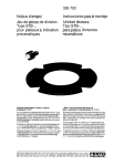
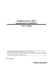
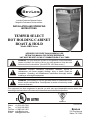
Innovative Foodservice Equipment Custom
Designed for Performance, Service and Value.
INSTALLATION AND OPERATING
INSTRUCTIONS
TEMPER SELECT
HOT HOLDING CABINET
ROAST & HOLD
Model: HRH Series
INTENDED FOR OTHER THAN HOUSEHOLD USE
RETAIN THIS MANUAL FOR FUTURE REFERENCE
UNIT MUST BE KEPT CLEAR OF COMBUSTIBLES AT ALL TIMES
!
WARNING: For your safety do not store or use gasoline or other flammable
vapors or liquids in the vicinity of this or any other appliance. Keep the area
free and clear of combustibles. (See ANZI Z83.14B, latest version)
!
!
WARNING: Improper installation, adjustment, alteration, service or
maintenance can cause property damage, injury or death. Read the
Installation, Operating and Maintenance Instructions thoroughly before
installing or servicing this equipment.
!
!
WARNING: Initial heating of unit may generate smoke or fumes and must be
done in a well-ventilated area. Overexposure to smoke or fumes may cause
nausea or dizziness.
!
This equipment has been engineered to provide you with year round dependable service when used
according to the instructions in this manual and standard commercial kitchen practices.
ANSI/NSF 4
Phone:
Fax:
Toll Free:
Website:
E-mail:
P/N 8832400 2/08
+1 (214) 421-7366
+1 (214) 565-0976
+1 (800) 441-1601
www.BevLes.com
[email protected]
BevLes
729 Third Avenue
Dallas, TX 75226
1
IMMEDIATELY INSPECT FOR SHIPPING DAMAGE
All containers should be examined for damage before and during unloading. The freight carrier has
assumed responsibility for its safe transit and delivery. If equipment is received damaged, either apparent
or concealed, a claim must be made with the delivering carrier.
A) Apparent damage or loss must be noted on the freight bill at the time of delivery. It must then be signed
by the carrier representative (Driver). If this is not done, the carrier may refuse the claim. The carrier can
supply the necessary forms.
B) Concealed damage or loss if not apparent until after equipment is uncrated, a request for inspection
must be made to the carrier within 15 days. The carrier should arrange an inspection. Be certain to hold all
contents and packaging material.
Installation and start-up should be performed by a qualified installer who thoroughly reads, understands
and follows these instructions.
The BevLes Company takes pride in the design and quality of our products. When used as intended and
with proper care and maintenance, you will experience years of reliable operation from this equipment. To
ensure best results, it is important that you carefully read and follow the instructions in this manual.
Installation and start-up should be performed by a qualified installer who thoroughly reads, understands
and follows these instruction.
If you have questions concerning the installation, operation, maintenance or service of this product, write
Technical Service Department BevLes Company, Inc., 729 Third Avenue, Dallas, TX 75226.
1. SAFETY PRECAUTIONS
Before installing and operating this equipment be sure everyone involved in its operation is fully trained and
aware of all precautions. Accidents and problems can result by a failure to follow fundamental rules and
precautions.
The following words and symbols, found in this manual, alert you to hazards to the operator, service
personnel or the equipment. The words are defined as follows:
!
DANGER: This symbol warns of imminent hazard which will result in serious injury or death.
!
!
WARNING: This symbol refers to a potential hazard or unsafe practice, which could result in
serious injury or death.
!
!
CAUTION: This symbol refers to a potential hazard or unsafe practice, which may result in minor or
moderate injury or product or property damage.
!
!
NOTICE: This symbol refers to information that needs special attention or must be fully understood
even though not dangerous.
!
2. GENERAL INFORMATION
THIS MANUAL SHOULD BE RETAINED FOR FUTURE REFERENCE
WARNING: Check the data plate on this unit before installation. Connect the unit only to the voltage
and frequency listed on the data plate. Connect only to 1 or 3 phase as listed on the data plate.
!
!
WARNING: Electrical and grounding connections must comply with the applicable portions of the
national electrical code and/or other local electrical codes.
!
!
WARNING: Do not use oven cleaners, caustic solutions or mechanical means to clean the
appliance as they will damage the interior stainless surface.
!
!
2
!
NOTICE: The unit when installed, must be electrically grounded and comply with local codes, or in
the absence of local codes, with the national electrical code ANSI/NFPA70- latest edition.
Canadian installation must comply with CSA-STANDARD C.22.2 Number 0 M1982 General
Requirements-Canadian Electrical Code Part II, 109-M1981- Commercial Cooking Appliances.
!
!
WARNING: This appliance must be serviced by an Authorized Service Technician only.
Disconnect the power supply before cleaning or servicing the cabinet.
Regular and thorough cleaning will help to keep the cabinet operating properly. If service is
required, contact an Authorized Service Agency, your dealer or the factory to obtain a qualified
technician for the required maintenance/service.
!
!
WARNING: Disconnect device from electrical power supply and place a Tag Out-Lockout on the
power plug, indicating that you are working on the circuit.
!
!
!
WARNING: Neglecting to keep fan opening clean could result in cabinet failure.
TABLE OF CONTENTS
SECTION
1
2
3
4
5
6
7
8
ITEM
PAGE
Safety Precautions
General Information
Installation Instructions
Operating Instructions
Cleaning Instructions
Specifications
Wiring Diagram
Parts Lists & Exploded Views
A. Half & Full Size (Full Width Models)
B. Half & Full Size (Narrow Width Models)
Warranty
9
2
2
3
4
9
10
11
12
12
14
16
IMPORTANT FOR FUTURE REFERENCE
Please complete this information and retain this manual for the life of the equipment. For
Warranty Service and/or Parts, this information is required.
Model Number
Serial Number
Date Purchased
The data plate for the unit is located on the left side panel on the upper rear of that panel. Check the voltage
requirements on the data plate. Connect the unit only to the voltage configuration specified on the data plate.
3. INSTALLATION INSTRUCTIONS
BEFORE USING THE CABINET:
1.
2.
3.
4.
!
Place cabinet on level floor in a well ventilated area.
Plug unit into proper wall outlet.
Push the power switch to ON and press the start button. Let run for one hour.
Let the cabinet cool and clean the inside with a mild detergent and hot water.
CAUTION: During operation the air is VERY HOT when the door is opened.
3
!
4. OPERATING INSTRUCTIONS
PROGRAMMING INSTRUCTIONS (TIMER VERSION)
To Set Cook Temperature:
1.
2.
3.
Press “COOK” button.
Use “ARROW” keys to set desired cook temperature.
Press “SET” button to set cook.
To Set Hold Temperature:
1.
2.
3.
Press “HOLD” button.
Use “ARROW” keys to set desired hold temperature.
Press “SET” button to set hold temperature.
To Set Cook Time:
1.
2.
3.
Press “TIME” button.
Use “ARROW” keys to set desired cook time.
Press “SET” button to confirm selected cook time.
Note: Safe food holding temperature is 140°F/60°C for beef and is higher for poultry and some other
products.
PROGRAMMING INSTRUCTIONS (PROBE VERSION)
To Set Cook Time or Probe Temperature:
1.
Press the Probe/Time Button until the LED indicates the mode you intent to use.
2.
Press the Time/Probe button
3.
Use Arrow keys to set desired cook time or probe temperature.
4.
Press Set button to confirm selected cook time or probe temperature.
To Set Cook & Hold Temperatures:
1.
Set the cook & hold temperatures the same as in the timer version listed above.
Note: Safe food holding temperature is 140°F/60°C for beef and is higher for poultry and some other
products.
OPERATION
Press “START” to begin cooking. The unit will heat to the cook temperature and stay there for the time
programmed or until the product probe reaches the programmed temperature. The unit will then lower the
temperature to the programmed hold temperature and remain there until the stop button is pushed. At any
time during the operation you can push the OVEN TEMP button and the temperature inside the cabinet will
be displayed.
NOTE: If the display is flashing power has been lost to the unit for longer than 3 seconds. Check the product
to make sure it has been properly cooked.
!
CAUTION: All foodservice equipment should be operated by trained personnel only. Do not allow
your customers to come in contact with any surface labeled “CAUTION HOT”. Never pour cold
water into heated unit. Never hold food below 140°F/60°C or above 40°F/4.45°C.
4
!
Time/Temp Display
Cook SP Button
Up Button
Hold LED
Cook LED
*Heat On LED
*Timed Mode LED Indicator
*Probe Mode LED Indicator
ON (I)
OFF (O)
POWER
Press “PROBE/TIMED” button to determine control mode.
PROGRAMMING INSTRUCTIONS
TO SET COOK TEMP:
1. PRESS "COOK" BUTTON
2. USE ARROW KEYS TO SET DESIRED COOK
TEMPERATURE
3. PRESS "SET" BUTTON TO SET COOK TEMPERATURE
TO SET HOLD TEMP:
1. PRESS "HOLD" BUTTON
2. USE ARROW KEYS TO SET DESIRED HOLD
TEMPERATURE
3. PRESS "SET" BUTTON TO SET HOLD TEMPERATURE
TO SET PROBE TEMPERATURE OR COOK TIME:
1. PRESS "PROBE/TIME" BUTTON
2. USE ARROW KEYS TO SET DESIRED PROBE
TEMPERATURE OR COOK TIME
3. PRESS "SET" BUTTON TO CONFIRM SELECTED PROBE
TEMPERATURE OR COOK TIME
PRESS "START" TO BEGIN COOKING
Set Button
COOK
SET
TIME
Roast & Hold
HOLD
OVEN
TEMP
START
STOP
CONVECTION COOKING & HOLDING SYSTEM
*Probe/Time Mode Selector Button
Down Button
Oven Temp Button
Hold SP Button
Start Button
Stop Button
*NOTE: NOT AVAILABLE ON ALL UNITS
Probe/Time SP Button
Button Descriptions
!
!
!
!
!
!
!
!
!
Cook SP - Displays current Cook SP temperature and allows changes.
Probe Time SP - Displays current probe temp or cook time SP (depending on cook mode
selected) and allows changes.
Hold SP - Displays current Hold SP temperature and allows changes.
Up - Increments displayed parameter value during programming.
Down - Decrements displayed parameter value during programming.
Set - Accesses the Setup mode and saves new parameter values.
Oven Temp - Momentarily displays current Oven temperature.
Start - Starts Cook cycle.
Stop - Aborts Cook cycle.
LED Descriptions
!
!
!
!
!
Probe Mode LED - Illuminates when the controller is in Probe cook mode.
Timed Mode LED - Illuminates when the controller is in Timed cook mode.
Heat On LED - Illuminates when Heat output is energized.
Cook LED - Illuminates while controller is in the Cook mode.
Hold LED - Illuminates when the controller is in the Hold mode.
5
OPERATOR MANUAL
Cook & Hold Controller
OPERATION:
When power is first applied to the controller the currently installed software version number will be displayed
for a few seconds and a self diagnostic routine will be initiated. If no errors are detected the Fan and Heat
output relays will energize and the oven will begin heating to the Hold setpoint temperature. The display will
flash until the Hold set point is achieved. When the oven has reached the Hold temperature the Hold lamp
will illuminate. The Fan and Heat outputs continue to cycle On & Off as required to maintain the oven at the
Hold set point until a Cook cycle is initiated.
Should a problem be detected during the self diagnostic routine at startup, the controller will suspend
operation until the error is corrected. An error code will be displayed to aid in troubleshooting (see self
diagnostic and troubleshooting section).
SETTING THE HOLD TEMPERATURE:
To change the Hold set point momentarily press the HOLD key (the Hold lamp will flash to show you are in
the Hold set point programming mode). Use the UP and DOWN ARROW keys to change the displayed
value as desired. Press the SET key to accept and store this new set point value.
Note: If no key is pressed for 10 seconds while in the programming mode the controller will automatically
return to the run mode and retain the original set point value.
SELECTING THE COOK MODE:
The SELECT key is used to select either a temperature terminated (Probe) or time terminated (Timed) cook
cycle. The appropriate Mode lamp will illuminate to show the current Mode setting. Upon power up the
controller will always default to the mode that was last used.
When the Probe mode is selected the probe temperature is continuously displayed. However, if the probe
sensor is not connected or is faulty the controller will lock-out (output relays will open) and a dashed line
followed by the numeral 2 will be displayed. The position of the line indicates the failure mode detected (see
the self-diagnostic & troubleshooting section).
SETTING THE COOK TEMPERATURE:
To change the Cook set point momentarily press the COOK key (the Cook lamp will flash to show you are in
the Cook set point programming mode). Use the UP and DOWN ARROW keys to change the displayed set
point value. Press the SET key to accept and store this new set point value.
SETTING PROBE TEMP OR COOK TIME:
To change the Probe Temperature Set point (Probe Mode) or Cook Time (Timed Mode) momentarily press
the PROBE TIME key (the appropriate Probe or Timed lamp will flash). Use the UP and DOWN ARROW
keys to change the displayed set point value. Press the SET key to accept and store this new set point.
INITIATING A COOK CYCLE:
A cook cycle is initiated by pressing the START key. After about 2 seconds the Fan and Heat relays will
energize and the oven will begin to heat to the Cook set point. During the Cook cycle the Fan relay remains
energized continuously while the Heat relay will cycle as required to maintain the oven at the cook set point.
During a timed cook cycle (Timed mode) the display will show the time remaining in the Cook cycle and
during a temperature terminated cook cycle (Probe mode) the probe temperature will be continuously
displayed. The actual oven temperature can be viewed at any time by momentarily pressing the OVEN key.
Approximately 10 seconds after the OVEN key is released the previous display will be restored.
Any set point values can be changed on the fly during a Cook cycle by pressing the appropriate
programming key and following the steps shown above.
When the cook cycle is complete (countdown timer reaches zero or the probe set point temperature is
reached) the controller automatically reverts to the Hold set point and an audible alarm sounds five (5) one
second bursts indicating the Cook cycle is complete.
6
The Cook cycle can be stopped at any time by pressing the STOP key. Once stopped, however, the cycle
must be restarted from the beginning.
POWER LOSS ALARM:
The display will flash when power is restored after a power loss. If power is lost during a Cook cycle, the
Cook cycle will continue where it left off upon restoration of power. Pressing any key will stop the flashing
display.
!
CAUTION: All foodservice equipment should be operated by trained personnel only. Do not allow
your customers to come in contact with any surface labeled “CAUTION HOT”. Never pour cold
water into heated unit. Never hold food below 150°F or above 40°F.
!
OVEN TEMPERATURE ALARM:
The Oven Temperature Alarm function can be turned On or Off at will (see Setup Programming below).
When activated the oven temperature alarm provides separate High and Low alarm set points. An audible
alarm sounds one second bursts and the display flashes whenever the oven temperature drops below the
low set point or exceeds the high set point. Pressing any key will silence the audible alarm but the display
will continue flashing until the temperature returns to an acceptable value.
Setup Programming
The Setup Mode is accessed by pressing and holding the SET key for several seconds until the"diFF"
prompt is displayed (while in Setup mode all outputs are de-energized). Momentarily press an UP or
DOWN ARROW key will display the current parameter value. Continuing to hold the ARROW key will
increment or decrement the value. Pressing the SET key will accept the new value and advance to the next
parameter. Repeatedly pressing the SET key will step through each parameter without making any
changes. Refer to the table below for a list of the programmable parameters, the range of acceptable
values and the factory defaults.
When locked ("Loc" parameter turned "On") the Setup Mode cannot be accessed as described above. The
Setup Mode can only be unlocked by removing power from the controller then reapplying power while
holding the SET key.
Display
diFF
PSLL
_tr
_AL
_ALL
_ALH
_F/C
_oF1
_oF2
_LoC
Parameter Description
Range of Values
Default
1 to 25°F or °C
0°F to 245°F
H=hrs/mins L=mins/secs
4°F
100°F
H
Alarm Low set point (Note 1)
Alarm High set point (Note 1)
Fahrenheit or Celsius display units (Note 2)
on or oFF
0 to Max SP
0 to Max SP
F or C
oFF
HSLL
CSLH
F
Oven sensor offset
Probe sensor offset
Parameter lock
_
+99°F
or °C
_
+99°F
or °C
on or oFF
0°F
0°F
oFF
On-Off differential for Cook & Hold set points
Probe Set point Limit Low
Time range for timed cook mode
Temperature Alarm
Notes:
1.
2.
These parameters only display if Alarm function is activated (on).
When switching from °C to of display some values may convert to illegal magnitudes (e.g.
50°C will convert to 122°Fwhich is greater than max. allowed of 99°F). Therefore, all
parameters should be checked for correct values when display units are changed.
SELF DIAGNOSTICS & TROUBLESHOOTING:
Error checking is done continuously while the controller is in operation. Should an error occur an error code
will be displayed. The error codes and the corrective action required are described below.
7
Display
Description
Corrective Action
“ 1“
At top of display
Oven sensor
open
Check for broken or disconnected lead wires or damaged
oven sensor. Repair wiring or replace sensor.
“ 1“
At bottom of display
Oven sensor
shorted
Check for shorted lead wire or damaged oven sensor. Repair
wiring or replace sensor.
“
2“
At top of display
Oven sensor
open
Check for broken or disconnected lead wire or damaged meat
probe sensor. Repair wiring or replace sensor.
“
2“
At bottom of display
Probe sensor
Shorted
Check for shorted lead wire or damaged meat probe sensor.
Repair wiring or replace sensor.
“
“
At center of display
Chksum error
Re-initialize the controller by removing power from the
controller then reapplying power while simultaneously
pressing the HOLD & DOWN ARROW keys. CAUTION:
Initializing removes all user programmed values from
memory and restores the default values.
CALIBRATION CABINET TEMPERATURE:
!
!
!
!
!
!
!
!
!
!
!
!
!
Make sure the cabinet temperature is stable it should have been run at the same temperature for at least
45 minutes with your measuring probe in place in the center of the cabinet.
Record the display temperature and your measured cabinets center temperature. If the two
temperatures are within 5°F do not attempt adjustment. There is typically that much error in most
measuring devices.
If the temperature difference is more than 5°F you may choose to adjust calibration
Unlock the programming function by pushing and holding the set button while turning off the power to
the unit and then turning it back on.
Push and hold the SET key for several seconds until “diFF” is displayed in the window
Release the SET key and then push it several times until “_oF1” is displayed in the window
Subtract the temperature measured in the center of the cabinet from the display temperature
Push the UP or DOWN arrow button until you reach the total from above.
Allow the cabinet temperature to stabilize for about ten minutes and recheck the temperature. The
display versus measured cabinet temperature should be within 5°F in not repeat the procedure.
Relock the programming function by pushing and holding the SET key for several seconds until “diFF” is
displayed in the window
Release the SET key and then push it several times until “_LoC” is displayed in the window
Push an arrow key until the display indicates “on”
Don’t push any buttons for ten (10) seconds and the control will drop out of the program mode.
CALIBRATION PROBE TEMPERATURE:
!
!
!
!
!
Make sure the temperature probe is stable it should have been in the product for a few seconds and if
should be reading the same temperature for several seconds before comparing to the display read out.
Make sure the two temperature probes are in close proximity.
Record the display temperature and the product temperature. If the two temperatures are within 3°F do
not attempt adjustment. There is typically that much error in most measuring devices.
If the temperature difference is more than 3°F you may choose to adjust calibration
Unlock the programming function by pushing and holding the set button while tuner off the power to the
unit and then turning it back on.
Push and hold the SET key for several seconds until “diFF” is displayed in the window
8
!
!
!
!
!
!
!
!
Release the SET key and then push it several times until “_oF2” is displayed in the window
Subtract the product temperature measured from the display temperature
Push the UP or DOWN arrow button until you reach the total from above.
Allow the product temperature to stabilize for about five minutes and recheck the temperature. The
display versus measured product temperature should be within 3°F in not repeat the procedure.
Relock the programming function by pushing and holding the SET key for several seconds until “diFF” is
displayed in the window
Release the SET key and then push it several times until “_LoC” is displayed in the window
Push an arrow key until the display indicates “on”
Don’t push any buttons for ten (10) seconds and the control will drop out of the program mode.
5. CLEANING INSTRUCTIONS
Daily Cleaning:
1. Turn off power switch and unplug the unit from the wall outlet.
2. Allow the unit to cool before cleaning.
!
WARNING: To avoid burns allow the unit to cool before cleaning.
!
3. Open the doors and remove all pans and hangers from the unit. Take them to the sink and
thoroughly clean.
4. Clean the interior and exterior of the cabinet with warm soapy water.
!
WARNING: Do not use steel wool or other abrasive cleaners. Do not use cleaners or sanitizers
containing chlorine, Iodine, ammonia or bromine as these will damage the finish on the stainless
steel.
!
!
WARNING: Do not use a water jet (pressure sprayer) to clean the unit. This could damage some of
the components.
!
5. Wash the control panel with a damp cloth, do not use excess water on the control panel.
6. Reinstall the hangers and pans. Leave the door partially open to allow these parts and the
interior of the cabinet to thoroughly dry.
Weekly Cleaning:
1. In addition to the daily cleaning remove the top air ducts from each side of the internal cabinet. To
remove these lift up and then pull away from the internal wall.
2. Remove the bottom air duct from each side of the internal cabinet. After the top air ducts have
been removed you can lift and pull away from the internal wall.
3. Take these parts to the sink and thoroughly clean.
!
WARNING: Do not use steel wool or other abrasive cleaners. Do not use cleaners or sanitizers
containing chlorine, Iodine, ammonia or bromine as these will damage the finish on the stainless
steel.
!
4. Reinstall these parts by installing the bottom air ducts first. Place the openings in the back of the
air duct over the spacers on the side wall and slide down into position. After the bottom air ducts
are installed repeat the process with the top air ducts.
Monthly Cleaning:
1. Vacuum the openings in the center of the rear panel.
!
Caution: Failure to clean these openings on a regular basis can cause the control components to
overheat and shorten their life.
9
!
6. SPECIFICATIONS
FULL WIDTH MODELS
FULL SIZE (HRHR74W12)
HALF SIZE (HRHR44W6)
ON
(I)
TOSET
1.
P
2. RES COOK P
RO
USEAS
3.
"COOK"
PR RROWTEMPGRAMMING
TOSET
ES
:
S "S
BUTT
1.
P
ET"KEY
IN
2. RES HOLDTE
STRUCTI
B S TOON
USEAS
3.
"HOL UT
PR RROW M TON SET
ONS
TOSET
ES
D" P:
TOSDESIR
S "S
BUTTON
1.
ET E
PR CO ET"KEY
D
COOK
2.USE
ES OK B S
CO
S "TMET UT TO
OK
3.
P ARROW
I IME: TON SET
TEMPERA
PR RES
"B
TOS DESIR
ESS S
"S K UT
ET E
"S ET" EYS TO
TU
HOLD HO
TART B TO N
RE
UT
LD
D TEM
" T TONSET
TE
O
PE MPE
BEGIN
TOCDESI
RA R
RE
ONFI
TUR ATURE
D
COOK
E
R CO
INGM SE OK
TIME
LECT
ED
CO
OK
TIM
E
OFF
PO (O)
WER
COOK
OVEN
TEMP
TIME
START
STOP
SET
HOL
D
Ro
CONV
as
t
ECTI
ON
&
COO
KI
NG
Ho
&
ld
HO
LDING
SYST
EM
ON
()I
OFF
POW (O)
ER
TO
1. SET
PRESS
COOK P
2.
ROGRA
USE
TEMP:
COOK"
"
3.
ARR
PRESS
M
TO
OW BUTTONMIN
G
"
1. SET SET"
KEYS
N
I S
PRESS
HOLD
TRU
2.
BUTTON
TO
USE
CTON
HOLD"
" TEMP:
SET
3.
I
ARR
PRESS
TO DESIRED
TO
S
OW BUTTON SET
"
1. SET SET"
KEYS
COOK COOK
PRESS
COOK
2.USE
BUTTON
TO
TIME:
TIME"
"
SET
3.
TEMPERA
ARROW
PRESS
DESIRED
PRESS
BUTTONTO SET
SET"
"
KE
TURE
HOLD HOLD
"START" YS
BUTTON
TO
TE TEMPERA
SET
TO
MPE
TO DESIRED
BEGINCO
RA
CONFIRM
TURE TURE
OKING COOK
SELECTE
TIME
D COOK
TIME
OV
EN
TEMP
TIM
E
STA
RT
STOP
CO
OK
HO
LD
SET
Ro
CONV
as
ECTI
ON
t&
COOK
Ho
ING
&
ld
HOLD
ING
SYST
EM
54.250
(1378mm)
ON (I)
OFF (O)
POWER
PROGRAMMING INSTRUCTIONS
TO SET COOK TEMP:
1. PRESS "COOK" BUTTON
2. USE ARROW KEYS TO SET DESIRED COOK TEMPERATURE
3. PRESS "SET" BUTTON TO SET COOK
TO SET HOLD TEMP:
1. PRESS "HOLD" BUTTON
2. USE ARROW KEYS TO SET DESIRED HOLD TEMPERATURE
3. PRESS "SET" BUTTON TO SET HOLD TEMPERATURE
TO SET COOK TIME:
1. PRESS "TIME" BUTTON
2.USE ARROW KEYS TO SET DESIRED COOK TIME
3. PRESS "SET" BUTTON TO CONFIRM SELECTED COOK TIME
PRESS "START" TO BEGIN COOKING
54.250
(1378mm)
COOK
SET
TIME
Roast & Hold
HOLD
OVEN
TEMP
START
STOP
CONVECTION COOKING & HOLDING SYSTEM
ON (I)
OFF (O)
POWER
PROGRAMMING INSTRUCTIONS
TO SET COOK TEMP:
1. PRESS "COOK" BUTTON
2. USE ARROW KEYS TO SET DESIRED COOK TEMPERATURE
3. PRESS "SET" BUTTON TO SET COOK
TO SET HOLD TEMP:
1. PRESS "HOLD" BUTTON
2. USE ARROW KEYS TO SET DESIRED HOLD TEMPERATURE
3. PRESS "SET" BUTTON TO SET HOLD TEMPERATURE
TO SET COOK TIME:
1. PRESS "TIME" BUTTON
2.USE ARROW KEYS TO SET DESIRED COOK TIME
3. PRESS "SET" BUTTON TO CONFIRM SELECTED COOK TIME
PRESS "START" TO BEGIN COOKING
COOK
SET
TIME
Roast & Hold
HOLD
OVEN
TEMP
START
STOP
CONVECTION COOKING & HOLDING SYSTEM
73.625
(1870mm)
43.625
(1108mm)
28.125
(714mm)
28.125
(714mm)
34.000
(864mm)
34.000
(864mm)
NARROW WIDTH MODELS
FULL SIZE (HRHR74W12)
HALF SIZE (HRHR44P16)
ON
(I)
OFF
PO (O)
WER
TOS
ET
1.PRESS
C
2.USE OO PROGRAM
K TE
"
3.PRESS
AR COO MP
ROWKEY
TOS
K"BU:
MING
ET "SET"BUTT T
1.PRESS
INS
TO
H
S
TR
2.USE OL
N
DTEMP: TOSET
UCTIONS
"
3.PRESS
AR HOLD" O N
ROWKEY
TOS
TO DESI
BU
SET RE
ET "SET"BUTT
1.PRESS
TTON
CO
COOD COOKTE
S TOSET
2US
OK
.
K
E ARROW
"TIM TIM O
3.PRESS
E: N T DE
MPERA
E"BUT
PRE
O
SETSIRE
SS "SET"BUTT
KE T
TU
"S
YSTOON
HOLD HOLD
RE
TA
D TEMP
RT
SE
"T
TEM
O ON TD
PE
BEGNTO ESI
ERATURE
RAT
I CO RED
URE
NFR C
COOKI
I M OO
NG SE K T
LECTE
IME
DC
OO
K
TIM
E
OV
TE EN
MP
COO
ST
TIME
K
ART
ST
OP
HO
LD
SE
T
Ro
CO
ast
NV
EC
TION
&
COO
Ho
KING
&
ld
HOLD
ING
SY
STE
M
ON
(I)
OF
F(
POWE
O)
R
TO
1. SETCOO
PRESS"CO
2.
PR
USE
K TEMP:
OGRA
3.
ARROW
PRESS"SE
OK"
MMING
TO
B
1. SETHOL
PRESS"HOT" KEYSUTT
INSTRU
ON
2.
USE
D B U TO
TEMP:
TT SETDESIR
3.
CTONS
ARROW
PRESS"SE
ON
I
LD"
TO
TO
B
SET ED
1. SETCOO KEYS
UT
PRESS"T T"
TON
COOKCO
2.USE
K B U TO
OK
3.
AR IM TIME:TTON SETDESIR
PRESS"SE
TEM
ROWE"
PR
PER
BUTTONTO SET
ESS
KEYS
ATUR
ED
"START"T
T"
HOLDHO
B
E
UT TO SET
LD
TEMPE
TEM
O TON
BEGIN
TO DESIRE
RA PER
CONFIR
TUR ATURE
D COOK
COO
E
KINGM
SELE TIME
CT
ED
CO
OK
TIME
OV
TE EN
MP
CO
TIM
E
ST
ART
STOP
HO
OK
LD
SET
Roa
CO
NV
EC
TIO
st
N
&
COOK
Ho
ING
&
ld
HO
LDING
SYS
TE
M
47.875
(1216mm)
ON (I)
OFF (O)
POWER
PROGRAMMING INSTRUCTIONS
TO SET COOK TEMP:
1. PRESS "COOK" BUTTON
2. USE ARROW KEYS TO SET DESIRED COOK TEMPERATURE
3. PRESS "SET" BUTTON TO SET COOK
TO SET HOLD TEMP:
1. PRESS "HOLD" BUTTON
2. USE ARROW KEYS TO SET DESIRED HOLD TEMPERATURE
3. PRESS "SET" BUTTON TO SET HOLD TEMPERATURE
TO SET COOK TIME:
1. PRESS "TIME" BUTTON
2.USE ARROW KEYS TO SET DESIRED COOK TIME
3. PRESS "SET" BUTTON TO CONFIRM SELECTED COOK TIME
PRESS "START" TO BEGIN COOKING
47.875
(1216mm)
47.750
COOK
SET
TIME
HOLD
OVEN
TEMP
START
STOP
Roast & Hold
CONVECTION COOKING & HOLDING SYSTEM
ON (I)
73.625
(1870mm)
OFF (O)
POWER
PROGRAMMING INSTRUCTIONS
TO SET COOK TEMP:
1. PRESS "COOK" BUTTON
2. USE ARROW KEYS TO SET DESIRED COOK TEMPERATURE
3. PRESS "SET" BUTTON TO SET COOK
TO SET HOLD TEMP:
1. PRESS "HOLD" BUTTON
2. USE ARROW KEYS TO SET DESIRED HOLD TEMPERATURE
3. PRESS "SET" BUTTON TO SET HOLD TEMPERATURE
TO SET COOK TIME:
1. PRESS "TIME" BUTTON
2.USE ARROW KEYS TO SET DESIRED COOK TIME
3. PRESS "SET" BUTTON TO CONFIRM SELECTED COOK TIME
PRESS "START" TO BEGIN COOKING
COOK
SET
TIME
HOLD
OVEN
TEMP
START
STOP
Roast & Hold
CONVECTION COOKING & HOLDING SYSTEM
43.625
(1108mm)
25.000
(635mm)
25.000
(635mm)
34.000
(864mm)
10
34.000
(864mm)
34.000
7. WIRING DIAGRAM
WIRING DIAGRAM - ROAST & HOLD
Fan
Power Line
Ground L1
120V
White - Lead #13
Black - Lead #12
Motor
208V
White - Lead #13
Black - None
Red - Lead #12
N
15
15
Power Switch
13
14
Pilot
Light
2
240V
White - Lead #13
Black - Lead #12
Red - None
12
13
4
7
11
1
9
14
1
12
3
5
Meat RTD
Optional
Temp
RTD
RTD 2
RTD 1
6
High Temp
Sensor #1
7
6
9
4
8
55
220V 120V AC-N
3
Air
10
Heater #1
Air
Heater #2 11
High Temp
Sensor #2
8. PARTS LISTS & EXPLODED VIEWS
PARTS LIST - HALF SIZE & FULL SIZE (FULL WIDTH MODELS)
ITEM
120V
P/N
208/240V
P/N
DESCRIPTION
1
781185
781185
Magnetic Latch
2
784692
784692
Lift-Off Hinge
3
781155
781155
Magnetic Gasket
4
781283
781283
Wire Hanger 5 x 25 Chrome
781284
781284
Wire Hanger 5 x 25 Stainless Steel (Optional)
5
741134
741134
Bottom Air Duct (Full Size Units Only)
6
741135
741135
Top Air Duct (Full Size Units Only)
7
780040
780040
5" Caster
8
780036
780036
5" Caster With Brake
9
781147
781147
Pull Handle (Full Size Units Only)
10
720319
720319
Door
11*
720321
720321
Door With Window
12*
783004
783004
Spacer - Air Duct
13
782068
701015
Power Cord
14
1101500
1101500
Stain Relief
15
1302200
1302200
Power Switch
16
741094
741094
Channel Support
17
781304
781304
Temperature Controller
18
784872
784872
Probe - Air
19
741485
741485
Air Duct - Half Size Units
20
781276
781276
Hi Limit Switch
21
784680
784682
Cooling Fan
22
781160
781163
Air Heater
Air Heater (Alternate High Watt Version)
781248
23
781279
781280
Blower Motor
24
1210810
1210810
Blower Wheel
25*
1101600
1101600
Terminal Block
26
2411450
2411450
Water Pan
*NOT SHOWN
12
EXPLODED VIEW - HALF SIZE (FULL WIDTH MODELS)
EXPLODED VIEW - FULL SIZE (FULL WIDTH MODELS)
13
13
14
14
23
23
20
20
23
23
13
22
18
14
18
20
18
20
21
21
24
24
15
22
22
24
13
24
21
21
ON
(I)
OF
F (O)
POW
ER
17
TO
1. SET
P
2. RES COO P
ROG
US
3. E S "C K TE
P AR OOK MP RAM
TO RES RO
MIN
" :
1. SET S "S W KE BU
G
P
ET" Y TT
INS
2. RES HOL
S ON
TRU
US
D BUTTTO
3. E S "H TE
CT
P AR OLD"M ON SET
IONS
P:
TO RES RO
T DE
1. SET S "S W KEBUTTO O SETSIRED
P
ET" Y
COO COO
2.USRES COO
S
S " K BUTTTO N
K
3. E AR
K
TIMETIME ON SET
P
TE
PRERES ROW " :
MPE
TO DE
SS S "S KEBUT
SETSIRED
RAT
"ST ET" Y TON
UR
HOLD HOLD
ST
ART BUTT
E
O
" TO ONSET
TEMP T
EMP
BE TO DE
ERAT
ER
GIN C SIR
ONF ED
UREATURE
COO
COO
KI IRM
NG SE K
TIM
LECT
E
ED
COOK
TIME
COOK
OVEN
TEMP
TIME
ST
ART
STOP
10
10
HO
LD
SE
T
Ro
NV
EC as
TION t
CO
26
&
CO
Ho
OK
ING
&
26
ld
HO
LD
ING
SY
ST
EM
4
4
14
14
15
ON
(I)
OFF
PO (O)
WER
17
TO
1. SET
PRE COO
2.
USESS K PRO
3.
PRE AR"COOTEM GRA
TO
SS ROW K" P: MMIN
BUT
1. SET "SET KEY
G
PRE HOL
IN
TO
2.
STR
USESS D " BUTS TO N
3.
UCTI
T
PRE AR"HOL EM TON SET
P
TO
ON
TO DES
SS ROW D" :
S
BUTTO
1. SET "SET KEY
SE IRED
PRE COO
T COO
2.US SS
"
S
COO
K BUT TO N
3. E A "TIM
K
TIM TON SET
K
PRE R
TEM
ROWE" E:
PRE SS
TO DES
PER
SS "SET K BUT
SE IRED
EYS TO
ATU
"STA
T HOL
"
N
HOL
RE
RT"BUT TO
D
TEMD TEM
TO TONSET
BEG TO DES
PER PE
ATU RATU
IN CONIRE
COOKF D
RE RE
IRM COO
ING S K
ELECTIME
TED
COO
K
TIME
9
OVE
TEMN
P
TIM
E
STA
RT
STO
P
HOL
D
9
6
6
COO
K
SE
T
Ro
NV
EC as
TIO t
CO
N
&
CO
OK
ING
Ho
&
ld
HO
LD
IN
G
SY
1
STE
M
26
26
16
16
27
1
27
5
10
10
2
2
1
1
3
3 19
3
3
2
7
7
4
4
8
8
7
7
8
8
2
PARTS LIST - HALF SIZE & FULL SIZE (NARROW WIDTH MODELS)
ITEM
120V
P/N
208/240V
P/N
DESCRIPTION
1
781185
781185
Magnetic Latch
2
784692
784692
Lift-Off Hinge
3
781156
781156
Magnetic Gasket
4
741563
741563
Bottom Air Duct
5
741561
741561
Top Air Duct (Full Size Units Only)
6
780040
780040
5" Caster
7
780036
780036
5" Caster With Brake
8
781147
781147
Pull Handle (Full Size Units Only)
9
720322
720322
Door
10*
720323
720323
Door With Window
11*
783004
783004
Spacer - Air Duct
12
782068
701015
Power Cord
13
1101500
1101500
Stain Relief
14
1302200
1302200
Power Switch
15
720515
720515
Pan Slide Assembly
16
781304
781304
Temperature Controller
17
784872
784872
Probe - Air
18
750382
750382
Spacer - Pan Slide Assy
19
781276
781276
Hi Limit Switch
20
784680
784682
Cooling Fan
21
781160
781163
Air Heater
781248
Air Heater (High Watt Version)
22
781279
781280
Blower Motor
23
1210810
1210810
Blower Wheel
24*
1101600
1101600
Terminal Block
25
2411450
2411450
Water Pan
*NOT SHOWN
14
EXPLODED VIEW - HALF SIZE (NARROW WIDTH MODELS) EXPLODED VIEW - FULL SIZE (NARROW WIDTH MODELS)
12
12
13
13
17
17
22
22
22
22
19
17
19
17
12
21
19
21
23
23
23
23
21
13
20
14
20
13
20
20
15
14
ON
(I)
OFF
POW (O)
ER
16
TO
1.PRSET
COOK PROG
2.U ESS
3.PRSE AR"C TEMP:RA
OO
MMING
TO ESS ROW K"
BUTTO
1.PRSET "SET"KEYSTO
INSTRU
HOLD
2.U ESS
N
BU
CT
TTON SET
3.PRSE AR"H TEMP:
IONS
OL
TO ESS ROW D"
TO DESIR
BU
SET ED
1.PRSET "SET"KEYSTO
TTO
COOK
COOKC
N
2.U ESS
OOKTEM
B
SEA "TIME"
TIMUTTON SET
3.PR
R
PER
PR ESS ROW B E:
TO DESIR
ESS "SET"KEYS
UTTON SET ED
ATU
"ST
HOLD H
RE
OLDTEM
ART" BU TO
TTONSET
TEMPE
TO
PERA
BEG TO DESIRED
RATUR
IN CON
T
CO FI CO
E URE
OKN RMSELOKTI
I G
EC ME
TEDC
OO
K TME
I
OV
TE EN
MP
COOK
TIME
ST
AR
T
ST
OP
HOL
SET
D
Ro
V as
CON
EC
TION
t&
COOK
Ho
& ld
HOL
IN
G
DIN
G
ON
(I)
OFF
PO (O)
WER
16
TO
1. SET
PRES CO
PR
2.
U
S"COKTE OGR
3. SE A
PRES R OOK"M P AMMNG
R
:
TO
I
S"SOW BU
1. SET
K
INSTR
PRES HO ET" EYS TTON
2.
UC
U
S"HLD T BUT TO SE
TION
T
3. SE A
PRES R OLDEMP ONTO T D
S
:
R
TO
ES
S"SOW " BUTT
SE IRED
1. SET
K
TC
PRES CO ET" EYS ON
OOKCOOK
2.U
S"TOKTI BUT TO
TE
3. SE ARROIME M TO SET
MPE
PRES
E: NTO D
PRE
ES
"B
RATU
SS S"S W KE UTTON SET IRED
RE
"S ET" YS
HOLD H
TA
OLD
RT BUT TO S
TE TEM
"T TO ET
MP
OB NTO DE
ERA PER
EGINC CON
SR
I E
TU AT
RE UR
FIRD COO
OOKN
E
KTI
I GM SELEC
M
TE E
DC
OOK
TM
I
E
25
25
OVEN
TEMP
TIME
COO
K
STA
RT
STOP
HOL
D
5
SET
Ro
V as
CON
25
ECT
ION
t&
Ho
COO
KING
25
SYS
TE
M
&
ld
HO
LDI
NG
8
SYST
EM
8
15
27
3
2
2
9
9
4
4
4
1
1
2
26
6
18
6
9
1
3
3
9
1
7
7
6
27
15
7
7
6
2
9. BEVLES COMPANY LIMITED WARRANTY
729 Third Avenue * Dallas, TX 75226
Phone: +1 (214) 421-7366
Fax: +1 (214) 565-0976
1.
Bevles warrants to the original purchaser that on the date the equipment is shipped (sold), it will be
free of defects in materials or workmanship. Bevles will, at it’s discretion, repair or replace, during
the warranty period printed below, any part that has a defect in material or workmanship that was
present when the product shipped from Bevles, and which manifests itself during the warranty
period under normal use and service.
!
!
Parts: Two* years from date of original shipment from the Bevles factory.
Labor: One** year from date of original shipment from the Bevles factory.
* Air Circulation Blower Assemblies (motors) and Power Switches shall be one year from date of
original shipment.
Calrod “Air” Heating Elements shall be three years from date of original shipment.
** All electrical components 120 days from date of original shipment.
2.
Bevles must be contacted, and pre-approval must be issued by the Bevles factory prior to any type
of service being performed. Bevles assumes no responsibility for any charges that were not expressly
authorized by the Bevles factory, or for any charges that exceed, in Bevles’ solejudgement, normal and
customary amounts.
3.
Bevles will pay UPS Ground charges for any part that has a defect in material or workmanship that was
present when the product shipped from Bevles, and which manifests itself during the first year of the
warranty period under normal use and service. All warranty replacement parts will ship F.O.B. Bevles
factory, Cheyenne, WY 82007.
4.
This warranty shall be void in its entirety if any abuse of, misuse of, alteration/modification of or
improper maintenance of original product occurs. If, at any time a claim is reported to Bevles, and the
purchaser is delinquent in payment for the product, warranty will not apply.
5.
Buyer’s Remedies-If a Bevles product fails due to a defect in material or workmanship in conformity
with the warranties in paragraph one, buyer shall notify Bevles of such failure within a reasonable time,
but in no event beyond fifteen (15) days of such discovery of defect in material or workmanship.
Bevles shall provide, in its sole discretion, either the repair or replacement of any defective or any nonconforming part. Bevles specifically disavows any other representation, warranty or liability relating
to the continued use of the product.
6
Exclusion of consequential and incidental damages-In no event shall Bevles be liable for any
incidental, special, indirect, or consequential damages, whether resulting from non-delivery or from
the use, misuse, or inability to use the product, or from defects in the product, or from
Bevles’ own negligence or other tort. This exclusion applies regardless of whether such damages are
sought for breach of warranty, breach of contract, negligence, or strict liability in tort or under any other
legal theory.
7.
Disclaimer of warranties-The warranties contained in paragraph one above are the exclusive
warranties given by Bevles and supersede any prior, contrary, or additional representations,
whether oral or written. Bevles hereby disclaims and excludes all other warranties-whether
expressed, implied, or statutory-including any warranty of merchantability, any warranty of
fitness for a particular purpose, and any implied warranties otherwise arising from course of
dealing or usage of trade.
4/02
1/05
16