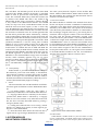
1
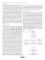
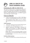
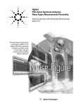
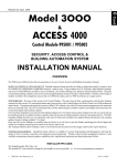
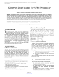
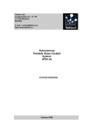
International Journal of Scientific & Engineering Research, Volume 5, Issue 2, February-2014 ISSN 2229-5518 113 Electronically Enhanced Commuter Transport Management Service Mr.Shivgunde Pramod Prakash Abstract— Public Transport is the most effective means of moving people. That is the first principle of urban transport policy; to provide mobility to people , not vehicles. A single bus carrying 60 people occupies a fraction of the road space that would be occupied if they all travelled in a car or even on 2-wheelers. Congestion can thus be reduced if more people use a bus and do not have to use their own vehicles. In addition the pollution from a bus per person is less than a 2-wheeler and much less that a car. In order for Public Transport to be attractive it must be convenient, comfortable and reliable. It also needs to be affordable and speedy. People those who are waiting for the buses at the bus stops for city or private buses will be looking eagerly for the bus they want to get in. But they can be able to trace the present location of the bus. This project Electronically enhanced commuter Transportation Management Service will be use full to find out the current location of the bus on a particular route for city buses. This project contains two embedded system modules one will placed inside the bus and the other will be placed at the bus stops. The location of bus can be find out using GPS and can be sent to bus stop using GSM as well as to public cell phone on request demand. The system consist of four modules; Bus station module, In-bus module, Base station module, Bus-stop module. Bus station has send initialization information containing the bus number and license number to In-bus module and Base station module using SMS. In-bus module then starts transmitting its location and number of commuters to BASE station module. BASE station module equipped with a ARM7 unit and GSM modem interfaced with PCs designed to keep track record of every bus and process the user request about a particular bus location out of bus station and updates buses locations on bus stops. BUS stop module installed on every bus stop and consist of a GSM modem, memory unit, and dot matrix display all interfaced to a ARM7. This module receives buses location information coming towards that stop from BASE station module and displays the information on a dot matrix display. The experimental analysis has been done based on the number of commuters and a recommendation report more over its check on the performance and services offered by transporters to commuters. IJSER Index Terms— GPS;GSM module; low power consumption 2148 ARM7 32-bit microcontroller; Bus station module; In-bus module; Base station module; Bus stop module; dot matrix display; commuter request. —————————— —————————— 1 INTRODUCTION Pune is city in the West of India, in the state of Maharashtra and is roughly 160 km east of Mumbai. As the city expanded unevenly, a large number of roads were built around the central portion of the city, According to a pune city report No. of Bus Stops: 3278 No. of Routes: 376 No. of Depots: 11 No. of Trips: 21998 per day but their existing problem of poor transportation services has grown to an alarming extent. Due to non-availability of prior information about the buses arrival schedule, people, students have to wait longer on bus stops especially in morning when they have to reach the offices, school, college in time. The buses are overloaded for most of the times which often results in some kind of fault occurrence in buses and people get late further [ ]. If Bus Stops are supposed to be provide modern, clean and comfortable for the commuter, the buses are fitted with GPS which enables real time information to be transmitted to each Bus Stops through Base Station so that a commuter always knows when the next bus will arrive. Simple to un- derstand maps are displayed so that using the bus becomes easy even for a first time user. We can also facilitate off-bus ticketing, just like for trains, so that commuters can buy tickets at the bus-shelter before boarding the bus. In this fashion the simple bus-based public transport system can be made to run almost like a metro, at a fraction of the cost. While the Delhi Metro cost Rs 160 crores/km, in Pune it will be built at Rs 5 crores/km![1] Consequently the dissatisfaction with the level and quality of public transportation service has lead those people who can afford it to turn to private modes of transportation. The private modes of transportation in Pune have contributed more than 85% (motor cycles = 50%, motor cars = 20%, taxi, rickshaws = 20%) as compared to public modes of transportation. Owing to poor infrastructure of roads in country, the annual growth rate of vehicles has created problems in controlling the traffic flow resulting in traffic congestion on roads. Also with the increased number of vehicles, the content of carbon mono-oxide and particulates IJSER © 2014 http://www.ijser.org International Journal of Scientific & Engineering Research, Volume 5, Issue 2, February-2014 ISSN 2229-5518 matter concentration is found to be 10 times higher than World Health Organization (WHO) in central parts of city thereby deteriorating the environment and causing lung diseases [2]. To reduce the number of private vehicles and improve the public modes of transportation in Pune ,the idea of Bus rapid transit system is proposed to apply over all pune region.[1]. This will also help in reducing the accidental rate seems to be a promising solution for enhancing public modes of transportation, it is costly to deploy. Another approach would be to introduce a technology based transportation management system that will help the commuters in getting informed about the exact schedule of buses. In this paper, a transportation management system is developed for enhancing public transportation services based on integration of GPS and GSM. GPS is used as a positioning device while GSM is used as communication link between different modules. These modules include BUS Station Module, In-Bus Module, BASE Station Module and BUS Stop Module. Bus Station Module contains a GSM engine interfaced to PC and transmits the bus index and its license plate number to BASE Station. At the same time, it turns on GPS receiver installed in the bus. The bus then starts transmitting its location to the BASE Station. The BASE Station comprises of a GSM engine interfaced to Aarm7 microcontroller for processing user request of bus location as well as a number of other GSM engines interfaced to various PCs each reserved for a separate bus to update the location information of that bus. The buses location data from BASE Station is sent to each bus stop. BUS Stop Module after receiving buses location data through GSM engine displays it on dot matrix display installed at each bus stop. The block diagram of the proposed system is shown in Fig. 1. 114 2. HARDWARE SPECIFICATIONS The following hardware components are used in building the entire system: A. GPS Reciever In order to keep track record of bus, a Garmin GPS35 receiver, powered from the bus main battery, is installed in each bus. The Garmin GPS35 is a complete GPS receiver and embedded antenna designed for a broad spectrum of OEM system applications. The GPS35 tracks up to twelve satellites at a time while providing one-second navigation updates and low power consumption. Its far-reaching capability meets the sensitivity requirements of land navigation as well as the dynamics requirements of high- performance aircraft. Internal memory backup allows the GPS35 to retain critical data such as satellite orbital parameters, last position, date, and time [4]. B. GSM Modem A wireless link between the modules is provided with Nokia 12i GSM module. Nokia 12i offers advance GSM connectivity and supports EDGE/GPRS and HSCSD with automated GSM connection establishment It is equipped to provide reliable remote connections and offers application level watchdogs, inbuilt self check mechanisms and a reliable Virtual Machine (VM) for JAVATM. Nokia 12i also supports reliable inbuilt internet protocols: TCP/IP for reliable data transfer, UDP/IP for audio and video streaming and HTTP for accessing web pages. The module can also be connected to an external GPS device that supports National Marine Electronics Association (NMEA) standard. The inbuilt NMEA parser can parse the location data from the output that it receives from the GPS device. External microcontroller can use AT commands to communicate with Nokia 12i and simple remote I/O applications can easily be controlled via text messages [5]. IJSER C. Microcontroller The LPC2148 microcontrollers are based on a 32/16 bit ARM7TDMI-S CPU with real-time emulation and embedded trace support, that combines the microcontroller with embedded high speed flash memory ranging from 32 kB to 512 kB. A 128-bit wide memory interface and a unique accelerator architecture enable 32-bit code execution at the maximum clock rate. For critical code size applications, the alternative 16-bit Thumb mode reduces code by more than 30 % with minimal performance penalty. Due to their tiny size and low power consumption, LPC2148 are ideal for applications where miniaturization is a key requirement, such as access control and point-of-sale[9]. Figure 1. Block Diagram of Transportation Management System D. Memory The LPC2141/2/4/6/8 incorporate a 32 kB, 64 kB, 128 kB, 256 kB, and 512 kB Flash memory system respectively. This memory may be used for both code and data storage. . When the LPC2141/2/4/6/8 on-chip bootloader is used, 32 kB, 64 kB, 128 kB, 256 kB, and 500 kB of Flash memory is available for user code. On-chip Static RAM (SRAM) may be used for code and/or data storage. The on-chip SRAM may be accessed as 8-bits, 16IJSER © 2014 http://www.ijser.org International Journal of Scientific & Engineering Research, Volume 5, Issue 2, February-2014 ISSN 2229-5518 bits, and 32bits. The LPC2148 provide 32 kB of static RAM respectively.The SRAM controller incorporates a write-back buffer in order to prevent CPU stalls during back-to-back writes. The write-back buffer always holds the last data sent by software to the SRAM. This data is only written to the B. SRAM when another write is requested by software (the data C. is only written to the SRAM when software does another write). If a chip reset occurs, actual SRAM contents will not reflect the most recent write request (i.e. after a "warm" chip reset, the SRAM does not reflect the last write operation). Any software that checks SRAM contents after reset must take this into account. Two identical writes to a location guarantee that the data will be present after a Reset. Alternatively, a dummy write operation before entering idle or power-down mode will similarly guarantee that the last data written will be present in SRAM after a subsequent Reset[9].256K Nonvolatile RAM (NV-Ram) DS1230Y-85 is used for storing data in In-BUS Module (in case of sparse GSM coverage) and at BUS Stop Module for displaying on dot matrix display. NV-RAM is selected because it combines the best of RAM and ROM: the read and write ability of RAM and non-volatility of ROM. The DS1230 Nonvolatile SRAM is 262,144-bit, fully static, nonvolatile SRAM organized as 32,768 words by 8 bits. Each NV SRAM has a self- contained lithium energy source and control circuitry which constantly monitors VCC for an out-oftolerance condition. When such a condition occurs, the lithium energy source is automatically switched on and write protection is unconditionally enabled to prevent data corruption [6,7,9]. 115 The entire system/network comprises of four modules: BUS Station Module, In-BUS Module, BASE Station Module and BUS Stop Module. The working and interconnection of these modules is described in this section. A. BUS Station Module BUS Station Module is installed at bus terminals from where the bus will depart. It contains a LASER and a GSM modem connected to a PC. When the bus enters the terminal pad, it is detected by the LASER sensor. The operator at the terminal enters the license plate number in database. A count number is then accordingly assigned to the bus e.g., bus leaving the terminal first will be assigned a number 1. The route number of bus along with the direction information, assigned count number and license plate number is sent to the BASE Station via GSM. An example of the transmitted header is of the form “2D01MH12X7272” where ‘2’ is the bus route number issued by Pune Mahanagar Parivahan Mandal Ltd (PMPML), ‘D’ will be downward direction of bus (‘U’ is upward direction), ‘01’ is the count number assigned to the bus and “MH12X7272”is license plate number of bus. An ‘ON’ signal is also transmitted to the In-BUS Module installed in the bus for initialization. The flow chart of module software is shown in Fig. 2. IJSER E. Battery Backup In-Bus Module is provided with an internal battery so that whenever power from main battery is disconnected, microcontroller continues to transmit the location to BASE station. A message is also sent to BASE station to notify it about the disconnection of main battery. When the power is resumed, the internal battery begins to recharge. F. .Alarms The microcontroller unit in In-BUS Module sends different alarm signals for different events to BASE Station Module. 1) On Backup Battery: When the main battery is switched off, a notification is sent to BASE station & buzzer. 2) Stoppage: When the bus is stationary for more than a specified time, BASE station is informed by a stoppage alarm. In case of an accident or any other fault occurred in bus, the driver can notify the BASE station by pressing a emergency button in bus. 3) Getting Late: When the bus is not covering a certain distance in a defined range of time, an alarm signal of getting late is sent to BASE station. D. 4) Route Deviation: When the bus deviates from the assigned route by a given margin, BASE station is notified. 3..SYSTEM MODULES AND NETWORK OPERATION Figure 2. Flow Chart of BUS Station Module B. In-BUS Module In-BUS Module is installed inside every bus and consists of a GPS receiver, a GSM modem, a NV-RAM, infrared object counting sensors, door opening/closing sensors and an emergency button; all interfaced to IJSER © 2014 http://www.ijser.org International Journal of Scientific & Engineering Research, Volume 5, Issue 2, February-2014 ISSN 2229-5518 LPC2148 (ARM7) based microcontroller. After receiving the initialization signal form BUS Station Module, this module starts transmitting bus location to the BASE Station. At each stop, when the driver opens the door, an interrupt is generated and microcontroller starts counting the numbers of commuters entering and leaving the bus with the help of infrared sensors. This count value on per stop basis is transmitted to the BASE Station. In case of an emergency situation (e.g., when fault occurs in bus), driver can press the emergency button to inform BUS and BASE Station units about the location of bus. The BUS station operator can then adjust the schedule accordingly and send an additional bus for facilitating the commuters. Microcontroller present in this module continuously calculates the difference in consecutive GPS locations. If the difference remains near zero for more than a designated time, then a getting late message is transmitted to the BUS and BASE stations. In case of sparse GSM coverage, location information is stored in nonvolatile RAM. After regaining the GSM network, previous locations are updated to the BASE station. The block diagram for this module is shown in Fig. 3 while flow chart of module software is shown in Fig. 4. Fig.3 Block diagram of In-Bus Module. 116 and message is sent to user. BASE station also monitors the emergency situations transmitted from In-BUS Module. In addition to this, the station keeps record of security issues and traffic congestion conditions and directs the driver to change the route if desired. The block diagram of the module is shown in Fig. 5 while module software is shown in Fig. 6. D. BUS Stop Module This module is installed at every bus stop to let the commuter know about the location of buses coming towards that stop. It comprises of a GSM modem, a NV-RAM and dot matrix display; all interfaced to LPC2148 (ARM7) based microcontroller. After receiving the bus location data in the form of stop names from BASE station, microcontroller stores it in non- volatile RAM. A sample message received by BUS Stop Module installed at ‘Swarget down route Bus Stop is of the form “2, Bharati vidyapeeth ; 2R, Balaji Nagar; 28,chaitanya nagar; 42A, Panchami Hotel. The message contains information of those buses only which will pass by the designated stop. First two digits of a sub-string denote the bus route number followed by the bus stop name which is the current location of bus coming towards the specified stop. Microcontroller after retrieving the stored information displays it on a 3x15 dot matrix display. The microcontroller refreshes the information with a rate of 10 seconds. In case of an emergency situation, the location of next incoming bus is displayed. The block diagram of this module is shown in Fig. 7 and flow chart of module is shown in Fig. 7. IJSER C. BASE Station Module This module is the central part of the network. It accepts location information of buses through respective GSM modems and maps the information on Google Map for visualization. It also receives the number of commuters entering and leaving the bus on per stop basis from In-BUS Module for statistical analysis. The message received is of the form “20, 10, 2345.3522N, 09022.0288E”. The first two strings denotes the number of commuters entering (20) and leaving (10) the bus respectively and next two strings denotes the location information; all separated by commas. Another GSM modem is used to get the user request of location information of a particular bus. An example of the query put by the commuter is of the form “2D” or “2D10”. In first instance i.e., “2D”, ‘2’ is the route number (Katraj to Shivaji Nagar) and ‘D’ designates the direction flag while in second instance i.e., “2D10”, additional digit ‘10’ denotes the bus stop number where the commuter is standing. The microcontroller attached with this GSM modem passes on the user request to the PC dedicated for that route number. The PC after processing the request data sends desired location information in form of bus stop name to microcontroller. The microcontroller then transmits this information back to the user. The information that commuter will receive contains the location of all buses out of terminal in desired direction in former query while in case of later query, he will get the location of those buses which are coming towards the particular bus stop number in desired direction along with time information. The time information is embedded in message to account for any delay in processing the user request. An example of the information received by the user is of the form “Bharti vidyapeeth gate, Chaitanya nagar, Balaji nagar, KK market - 12:30 P.M.” where first four strings are bus stops names telling where the buses are currently followed by the time on which the location information is get from the map IJSER © 2014 http://www.ijser.org Figure 3. Block Diagram of In-Bus Module. International Journal of Scientific & Engineering Research, Volume 5, Issue 2, February-2014 ISSN 2229-5518 117 of data between the modules. A new service, to facilitate the people who use public transport for traveling, is introduced inside the city. The service provides the user with current IJSER Figure 5.Block Diagram of BASE Station Module. Figure 4. Flow chart for In-Bus module. 4..STATISTICAL ANALYSIS AND RECOMMENDATIONS BASE station utilizes the commuter information on per stop basis to carry out the statistical analysis. A GUI, shown in Fig. 8. A recommendation report is also generated by the software which highlights the regions of greater emphasis. These are the regions where buses are more overloaded. The solution to the problem lies in increasing the number of buses on routes which are densely crowded or introduce new overlapping routes to compensate the demand. BASE station transmits the statistical data along with the recommendation report PMPML through internet at the end of day or as per request of transportation department [1]. 5. CONCLUSIONS In this paper, design and development of a low cost transportation management system based on integration of GPS and GSM data is described. The system comprises of various modules which are wirelessly linked with GSM modems. Cost effective SMS service of GSM network is used for the transfer IJSER © 2014 http://www.ijser.org Figure 6. Flow Chart for Base Station Module International Journal of Scientific & Engineering Research, Volume 5, Issue 2, February-2014 ISSN 2229-5518 118 location information of desired buses based on which the user can adjust his schedule accordingly. The service therefore vanishes the need of waiting at the bus stop thus saving a lot of time. For the commuters not utilizing the service, displays are installed at bus stop to let them know the buses location coming towards that stop. The system is also efficient in handling the emergency situations e.g., in case some kind of technical fault occurred in bus, the operator at bus terminal is informed and the departure time between the buses is reduced. 6. FUTURE WORK The system can be made automatic by installing cameras or bar code reader at bus terminals which can automatically read the license plate number of buses thereby eliminating the operator. An automatic route guider display can be installed in buses to better update the alternative route in case of serious road congestions. Fare collecting system can also be automated by providing another mobile service to which all the commuters using public transport are subscribed. IJSER Figure 8. GUI showing Statistical Data of route Katraj to Shivaji nagar, Pune. . BASE station transmits the statistical data along with the recommendation report PMPML through internet at the end of day or as per request of transportation department. Figure 7. Flow Chart of BUS Stop Module ACKNOWLEDGMENT Authors would like to acknowledge support and funding from Shri Siddheshwar Women’s Polytechnic, Solapur for this work. REFERENCES [1] Route information http://www.pmpml.org/ [2 ]Muhammad Imran and Nicholas Low, “Time to change old paradigm: Promoting sustainable urban transport in Lahore Pakistan,” International Journal of World Transport Policy and Parctice, vol. 9, pp. 32-39, Nov 2003. [3] Muhammad Imran and Nicholas Low, “Impact of global institutions on urban transport in Pakistan cities,” Proc. 39thISoCaRP Congress, 2003. [4] Available [online]: www.garmin.com/products/gps35 [5] Available [online]: www.d-d-s.nl/fotosokia/n12i_datasheet_a4_v2.pdf [6] Available [online]: www.alldatasheet.com [7] M. A. Mazidi, J. C. Mazidi, R. D. Mckinaly, The 8051 Microcontroller and Embedded Systems, Pearson Education, 2006. [8] Available [online]: www.mathworks.com [9] Available [online]: Data sheet LPC 214x USER MANUAL http://www.keil.com/dd/docs/datashts/philips/user_man ual_lpc214x.pdf IJSER © 2014 http://www.ijser.org