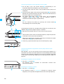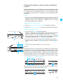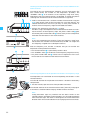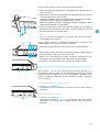
1
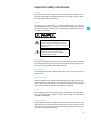
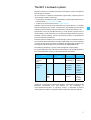
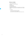
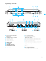
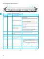
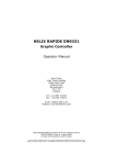
NET 1
Instructions for use
Contents
Important safety instructions ................................................................................. 4
Important safety information ................................................................................. 5
Accompanying documentation ........................................................................................ 6
The NET 1 network system ...................................................................................... 7
Delivery includes ........................................................................................................ 8
Operating controls ..................................................................................................... 9
LEDs on the front panel of the NET 1 ............................................................................10
LEDs on the rear panel of the NET 1 .............................................................................11
Putting the NET 1 into operation ......................................................................... 12
Setting up the NET 1 ........................................................................................................12
Rack-mounting the NET 1 ...............................................................................................12
Fitting the device feet (“table top” use only) ............................................................12
Connecting the power supply ........................................................................................13
Connecting the devices ....................................................................................................13
Connecting several NET 1 ................................................................................................14
Connecting the NET 1 to a PC .........................................................................................15
Installing the “Wireless Systems Manager” software ..............................................15
Switching a NET 1 system on .........................................................................................16
Updating the firmware ....................................................................................................16
Operation with systems of the
evolution wireless G2 series .................................................................................. 17
Performing a frequency scan in “Stand Alone” operating mode ...........................17
Performing a frequency scan for wireless monitoring systems (IEM) ...................18
Performing a frequency scan for wireless microphone systems ............................21
Operation with 3000/5000 series systems ....................................................... 24
Mixed operation of evolution wireless G2 series systems and
3000/5000 series systems ................................................................................... 25
If a problem occurs ... .............................................................................................. 26
Problems that may occur when putting the NET 1 into operation .........................26
Problems that may occur during operation ................................................................27
Specifications ........................................................................................................... 28
Connector assignment .....................................................................................................28
Accessories/replacement parts ............................................................................ 29
Manufacturer declarations .................................................................................... 30
Thank you for choosing Sennheiser!
We have designed this product to give you reliable operation over many years. Over
60 years of accumulated expertise in the design and manufacture of high-quality
electro-acoustic equipment have made Sennheiser a world-leading company in this
field.
Please take a few moments to read these instructions carefully, as we want you to
enjoy your new Sennheiser products quickly and to the fullest.
3
Important safety instructions
1. Read these instructions.
2. Keep these instructions.
3. Heed all warnings.
4. Follow all instructions.
5. Do not use this apparatus near water.
6. Clean only with dry cloth.
7. Do not block any ventilation openings. Install in accordance with the
manufacturer’s instructions.
8. Do not install near any heat sources such as radiators, heat registers,
stoves, or other apparatus (including amplifiers) that produce heat.
9. Do not defeat the safety purpose of the polarized or grounding-type plug.
A polarized plug has two blades with one wider than the other. A
grounding type plug has two blades and a third grounding prong. The wide
blade or the third prong are provided for your safety. If the provided plug
does not fit into your outlet, consult an electrician for replacement of the
obsolete outlet.
10.Protect the power cord from being walked on or pinched, particularly at
plugs, convenience receptacles, and the point where they exit from the
apparatus.
11.Only use attachments/accessories specified by the manufacturer.
12.Use only with the cart, stand, tripod, bracket, or table specified by the
manufacturer, or sold with the apparatus. When a cart is used, use caution
when moving the cart/apparatus combination to avoid injury from tipover.
13.Unplug this apparatus during lightning storms or when unused for long
periods of time.
14.Refer all servicing to qualified service personnel. Servicing is required
when the apparatus has been damaged in any way, such as power-supply
cord or plug is damaged, liquid has been spilled or objects have fallen into
the apparatus, when the apparatus has been exposed to rain or moisture,
does not operate normally, or has been dropped.
Rack mounting
When installing the device in a closed or multi-rack assembly, please consider
that, during operation, the ambient temperature within the rack may
significantly rise above room temperature. However, the ambient
temperature within the rack must not exceed the temperature limit specified
in the specifications.
When installing the device in a rack, take good care not to affect the
ventilation required for safe operation or provide additional ventilation.
Make sure the mechanical loading of the rack is even to avoid a hazardous
condition such as a severely unbalanced rack.
When installing the device in a closed or multi-rack assembly, please note
that intrinsically harmless leakage currents of the individual devices may
accumulate, thereby exceeding the allowable limit value. As a remedy,
ground the rack via an additional ground connection.
4
Important safety information
Warning
To reduce the risk of fire or electric shock, do not expose this device to rain or
moisture. Do not open the cabinet; dangerous high voltage is present. Refer
servicing to qualified personnel only.
Caution
To prevent fire, shock hazard, or annoying interference, use only the
recommended accessories. To reduce the risk of electric shock, do not remove
the unit cover or back. There are no servicable parts inside. Refer servicing to
qualified personnel only.
This symbol is intended to alert the user to the
presence of uninsulated dangerous voltage
within the product’s enclosure that may be of
sufficient magnitude to constitute risk of fire or
electric shock.
This symbol is intended to alert the user to the
presence of important operating and
maintenance instructions in the literature
accompanying this product.
Power sources
This device should be operated only from the type of power source indicated
on the marking label. If you are not sure of the type of power supply to your
home, consult your dealer or local power company.
Overloading
Do not overload wall outlets and extension cords as this may result in fire and
electric shock.
Objects and liquids
Never push objects of any kind through openings into this device as they may
touch dangerous voltage points or short out parts that could result in fire or
electric shock. Never spill liquids of any kind onto the device. Should spillage
occur, unplug the device and have it checked by a technician.
Servicing
Do not attempt to service this device yourself as opening or removing covers
may expose dangerous voltage or other hazards. Refer all servicing to
qualified personnel only.
Replacement parts
When replacement parts are required, be sure the service technician has used
replacement parts specified by the manufacturer or those having the same
characteristics as the original part. Unauthorized substitutions may result in
fire, electric shock, or other hazards.
5
Safety check
Upon completion of any service or repairs to this device, ask the service
technician to perform safety checks to determine that the device is in safe
operating order.
Accompanying documentation
In addition to these instructions, please also refer to the
y instructions for use of the rack-mount and portable devices
y instructions for use of the “Wireless Systems Manager” PC software
y installation manual for the “Wireless Systems Manager” PC software
6
The NET 1 network system
The NET 1 allows you to control and monitor Sennheiser wireless microphone
and monitoring systems.
Its main feature is frequency management, significantly simplifying the set
up of complex wireless systems by
y scanning the channel banks and automatically assigning the frequencies to
the connected rack-mount devices and
y wirelessly transferring data to the portable devices.
One NET 1 device with up to 10 connected rack-mount devices is a suitable
tool for configuring your system. A second, daisy-chained NET 1 allows you to
configure systems comprising up to 20 devices, without the need for a PC.
Applications with up to five NET 1 devices, i.e. multi-channel systems with up
to 50 channels, can be controlled via a PC and the supplied “Wireless Systems
Manager” (WSM) software. These multi-channel systems are connected to
the PC via Ethernet connections.
The WSM software enables real-time monitoring as well as remote controlling
of all relevant device parameters during live operation, ensuring an excellent
overview of the system at all times. In addition, the WSM software allows you
to integrate and control devices of the Sennheiser 3000/5000 series.
The following Sennheiser systems can be configured using the NET 1:
For correct operation, only transmitters and receivers that are equipped with
the same compander system can be combined with each other:
Compander
system
System
Receivers
Transmitters
Wireless
monitoring
system
ew IEM G2
HDX
portable:
rack-mount:
EK 300 IEM G2 SR 300 IEM G2
Wireless
microphone
systems
ew G2
HDX
rack-mount:
EM 500 G2
EM 550 G2
EM 300 G2
portable:
SK 500 G2
SKM 5xx G2
SKP 500 G2
SK 300 G2
SKM 3xx G2
3000/
5000
series
HiDyn plus™
rack-mount:
EM 3532
portable:
SK 5212
SKM 5200
SKP 3000
Sennheiser is continuously improving the NET 1 and the WSM software. We
therefore recommend that you register on our homepage at
www.sennheiser.com/net1 to regularly receive a newsletter providing
information on the NET 1, the WSM software and future software updates.
7
Delivery includes
y 1 NET 1 with rack-mounting kit
y 3 power cords (with EU, US and UK plug)
y Device feet
y 10 RJ 10 data cables
y 1 RJ 45 Ethernet cable
y Instructions for use of the NET 1
y “NET” stickers to mark the receivers and transmitters that have had the
latest firmware installed after you have updated them from the supplied
CD-ROM
y 1 CD-ROM with:
- the “Wireless Systems Manager” PC software
- the firmware update software (SENNPKG file)
- the instructions for use of the “Wireless Systems Manager” software
8
Operating controls
Infra-red interface (DATA LINK),
backlit in blue
3-pin IEC power connector
“CHANNEL” LED (1 to 10), green
5 x sub-D socket for connecting
EM 3532 twin receivers
쐋 “SCAN” LED, yellow
LAN 2 Ethernet connection, Neutrik RJ 45 socket
“READY” LED, green
LAN 1 Ethernet connection, Neutrik RJ 45 socket
“REMOTE” LED, yellow
“DATA” LED, yellow (Ethernet)
“ERROR” LED, red
10 x RJ 10 socket for connecting rack-mount receivers
or transmitters (IEM) of the evolution wireless G2
series
MODE button
“DATA LINK” LED, yellow
Channel buttons (1 to 10)
ON/OFF switch
Type plate
Plate with MAC addresses
Latch for Ethernet connection
(when using the matching Neutrik plug)
9
LEDs on the front panel of the NET 1
LED
Color of LED
LED lights up permanently
IR
interface backlit in blue
NET 1 is ready to transfer the
frequencies and settings.
CHANNEL green
(1 to 10 )
NET 1 has detected the conncted
devices.
IR frequency transfer is
successfully completed
LED...
–
...flashes slowly:
Rack-mount receivers
After the frequency scan, NET 1 indicates the receivers
belonging to the frequency range of the receiver that has
performed the scan.
Rack-mount transmitters (IEM):
After the frequency scan with a portable receiver (IEM)
and the frequency transfer to the transmitters (IEM) of
the correspondingfrequency range, the receivers (IEM) can
now be configured.
...flashes rapidly:
NET 1 is ready to transfer the frequencies and settings to a
portable device.
...flashes once every second:
The firmware of the connected evolution wireless G2
device is not the latest (see the instructions for use of the
“Wireless Systems Manager” software).
SCAN 쐋
yellow
...flashes slowly:
With the MODE button pressed,
NET 1 indicates that it is ready for A frequency scan is being performed.
scanning
READY green
NET 1 is ready for operation
REMOTE yellow
NET 1 is PC controlled or
controlled via an additional NET 1
(“remote operation”)
ERROR red
...flashes:
NET 1 has been switched on and is being initialized.
–
...flashes rapidly for approx. 3 seconds:
y An error has occured during IR data transfer (e.g. wrong
–
DATA LINK yellow
10
A device is connected.
frequency range of the device); data transfer must be
repeated.
y The MODE button is being pressed but NET 1 cannot
switch to scan mode because:
– no receiver is connected.
– NET 1 is PC controlled or controlled via an additional
NET 1 (“remote operation”).
...flashes slowly:
NET 1 is ready to transfer the frequencies and settings.
LEDs on the rear panel of the NET 1
LED
Color of LED
LED lights up permanently
DATA (Ethernet)
yellow
NET 1 is connected to a PC or an ...flashes rapidly:
additional NET 1
Data is being transferred within the network.
LED...
11
Putting the NET 1 into operation
Setting up the NET 1
Strong extraneous light may interfere with the data transfer via the infrared
interface. Therefore, position the NET 1 so as to avoid interference from
extraneous light.
Rack-mounting the NET 1
CAUTION!
Danger of heat damage!
When installing the device in a closed or multi-rack assembly,
please consider that, during operation, the temperature
within the rack may rise significantly.
왘 Make sure not to affect the ventilation required for safe
operation or provide additional ventilation.
CAUTION!
Danger of electric shock!
When installing the device in a closed or multi-rack assembly,
please note that intrinsically harmless leakage currents of the
individual devices may accumulate, thereby exceeding the
allowable limit value.
왘 Ground the rack via an additional ground connection.
All NET 1 are delivered with the rack-mounting kit pre-assembled.
왘 Slide the NET 1 into the rack.
왘 Secure the NET 1 to the rack.
Fitting the device feet (“table top” use only)
When the NET 1 is not installed in a rack avoid the NET 1 device sliding around
and reduce the chance of damage to the device and to any surface on which
it is placed by fixing the four soft rubber self adhesive feet to the base of the
NET 1 device in the positions indicated.
Note:
Some furniture surfaces have been treated with varnish, polish or
synthetics which might cause stains when they come into contact with
other synthetics. Despite a thorough testing of the synthetics used by us,
we cannot rule out the possibility of staining.
왘 Ensure that the base of the device is clean and free from grease before
fitting the rubber feet.
왘 Fix the rubber feet to the base of the device by peeling off the backing
paper and fitting them as shown in the diagram on the left.
12
Connecting the power supply
Connect the power supply, but keep the NET 1 switched off.
왘 Connect the supplied power cord to the socket .
왘 Connect the power cord to a wall mains outlet.
Connecting the devices
Note:
Only use original Sennheiser cables to connect the devices (see
“Accessories/replacement parts” on page 29).
The NET 1 has five connection groups. Devices can be connected either to the
sub-D socket or to the two RJ 10 sockets of a connection group, not to both:
Socket
Devices
RJ 10 socket y two EM 300 G2 or EM 500 G2 receivers
y one EM 550 G2 twin receiver
y two SR 300 IEM G2 transmitters
Sub-D socket y one EM 3532 twin receiver
Connecting evolution wireless G2 devices
왘 Use separate RJ 10 cables to connect the service interface (DATA) of each
evolution wireless G2 device to the desired RJ 10 socket on the NET 1.
왘 When connecting an EM 550 G2 twin receiver, use two cables to connect
the individual receivers DATA A / DATA B to two RJ 10 sockets on the NET 1.
Note:
NET 1
For multi-channel systems, you can daisy-chain several NET 1 devices.
Make sure that within the network the number of connected devices per
frequency range does not exceed the number of free preset frequencies
within a channel bank.
EM 300 G2
DATA
Serie
Number of free preset frequencies per channel bank
ew 300 G2
8 (a maximum of 8 receivers can be connected)
ew 500 G2
20 (a maximum of 20 receivers can be connected)
ew 550 G2
20 (a maximum of 10 twin receivers can be
connected)
ew 300 IEM G2
12 (a maximum of 12 transmitters can be connected)
When using more than eight receivers from different evolution wireless G2
series, at least one EM 500 G2 or EM 550 G2 receiver per frequency range
must be connected to the first connection group. The preset frequencies of
these receivers are then used for assigning the frequencies.
13
Connecting an EM 3532 twin receiver
왘 To connect an EM 3532 twin receiver to the sub-D socket on the NET 1,
use only the right-hand (as viewed from the rear of the receiver) common
data interface DATA IN/OUT as shown in the diagram below.
RX 2
RX 1
EM 3532
NET 1
RX 1
RX 2
Connecting several NET 1
14
왘 Connect two NET 1 via the sockets LAN 1 and LAN 2 using an
Ethernet cable. The sockets LAN 1 and LAN 2 are identical, so it doesn’t
matter in which order you connect them.
Connecting the NET 1 to a PC
The following applications with up to five NET 1 require the connection of
a PC :
y Systems with up to 50 evolution wireless G2 rack-mount devices
y Systems with up to 25 EM 3532 twin receivers
y Mixed systems consisting of evolution wireless G2 devices and EM 3532
twin receivers
The MAC addresses of the NET 1 are indicated on the type plate .
왘 Connect one of the sockets LAN 1 or LAN 2 of the first NET 1 to the
PC using an Ethernet cable.
Notes:
y It is also possible to connect up to five NET 1 to a PC using a switch or a
router with switching function.
y Do not use a network hub! Attempting to use a hub with NET 1 may
cause network failure or other data communications problems.
왘 Then connect additional NET 1 via the sockets LAN 1 and LAN 2 using
Ethernet cables. The sockets LAN 1 and LAN 2 are identical, so it doesn't
matter in which order you connect them.
Installing the “Wireless Systems Manager” software
In order to operate the NET 1 with a PC, you have to install the “Wireless
Systems Manager” software (refer to the software installation manual).
15
Switching a NET 1 system on
For reliable detection of the rack-mount devices, we recommend the
following sequence:
Switching the devices on
왘 Switch on the devices connected to the NET 1.
Switching the NET 1 on
왘 Press the ON/OFF switch to switch on the NET 1.
After switch-on, the green “READY” LED flashes, indicating that the
NET 1 is being initialized. As soon as the NET 1 is ready for operation, the
“READY” LED lights up permanently.
If a connected device is detected by the NET 1, the corresponding green
“CHANNEL” LED lights up permanently and the infrared interface is
permanently backlit in blue.
Note:
It is OK to switch on all rack-mount devices and the NET 1 simultaneously
via a main switch if one exists.
Starting the “Wireless Systems Manager” software
왘 Start the “Wireless Systems Manager” software as described in the
instructions for use of the software.
Once communication between the PC and the NET 1 is working properly,
the yellow “REMOTE” LED on the NET 1 (and on all daisy-chained NET 1)
lights up permanently.
Updating the firmware
The NET 1 is compatible with previously released Sennheiser wireless systems
of the evolution wireless G2 series or the 3000/5000 series (see table on
page 7) – provided they have the latest firmware installed.
Devices that have NET 1-compatible firmware installed can be identified by
one or both of the following:
y marked with “NET” on their type plate or
y an additional menu item “Software-Revision” or “SW REV” can be found in
the operating menu.
If the green “CHANNEL” LED continues to flash, update the firmware in the
corresponding device using the NET 1 and the “Wireless Systems Manager”
software. For information on how to update the firmware of the devices,
please refer to the instructions for use of the “Wireless Systems Manager”
software.
Note:
The firmware in the EM 3532 twin receiver must not be updated.
16
Operation with systems of the
evolution wireless G2 series
When using devices of the evolution wireless G2 series (see table on page 7),
there are two operating modes:
1. “Stand Alone” operating mode (without a PC):
y one NET 1 with up to 10 connected devices
y two daisy-chained NET 1 with up to 20 connected devices
2. “Remote” operating mode (with a PC):
y up to five daisy-chained NET 1 connected to a PC with up to 50
connected devices
Note:
In “Remote“ operating mode, the frequency scan can only be performed
using the “Wireless Systems Manager” software (see the instructions for
use of the “Wireless Systems Manager” software).
The rack-mount receivers and transmitters (IEM) may well have different
frequency ranges.
Performing a frequency scan in “Stand Alone”
operating mode
With the frequency scan, the NET 1 searches for free frequencies for multichannel operation (see the instructions for use of the evolution wireless G2
devices).
There are the following possibilities:
Devices connected to the NET 1 The frequency scan is performed
Rack-mount receivers only
y using a rack-mount receiver as
described from page 21
SR 300 IEM G2 rack-mount
transmitters only
y using an EK 300 IEM G2 portable
Rack-mount receivers and
SR 300 IEM G2 transmitters
y first using an EK 300 IEM G2 portable
receiver as described from page 18
receiver as described from page 18 and
y then using a rack-mount receiver as
described from page 21
17
Performing a frequency scan for wireless monitoring
systems (IEM)
For wireless monitoring systems, the frequency scan is performed using the
EK 300 IEM G2 portable receiver. The frequencies of a selected channel bank
are then assigned to all SR 300 IEM G2 rack-mount transmitters of this
frequency range. Subsequently, the frequencies are transferred to the
corresponding portable receivers.
Switching the portable transmitters off
왘 Switch off all portable transmitters that are to be configured via the NET 1.
Preparing the frequency scan
왘 Press and hold the MODE button on the NET 1.
The NET 1 selects one rack-mount device from each of the frequency
ranges. The “CHANNEL” LEDs assigned to these devices light up.
When two NET 1 are daisy-chained, pressing the MODE button automatically determines the “master” NET 1. The “REMOTE” LED of the
“slave” NET 1 lights up and its MODE button is deactivated.
To determine the desired frequency range for the frequency scan, you first
have to select a rack-mount transmitter (IEM) belonging to the desired
frequency range as follows:
왘 Press the corresponding channel button .
The green “CHANNEL” LEDs of the rack-mount transmitters (IEM) with
the same frequency range flash. The infrared interface is permanently
backlit in blue and the yellow “SCAN” LED 쐋 flashes.
The RF signals of the rack-mount transmitters are muted. The display
backlighting changes from green to red.
Example:
The connection groups 1 to 4 of the NET 1 are occupied by transmitters (IEM).
The connection groups 6 to 10 are occupied by rack-mount receivers. After
pressing the MODE button , the green “CHANNEL“ LEDs for the first rackmount transmitter (connection group 1) and the first rack-mount receiver
(connection group 5) light up. The “CHANNEL“ LEDs of the other rackmount devices do not light up, i.e. they belong to the same frequency range.
1.
Wireless
Wireless
monitoring system microphone system
After pressing the channel button , both the “CHANNEL“ LEDs 2 to 4 of
the monitoring system and the yellow “SCAN” LED 쐋 flash.
2.
18
Performing the frequency scan using the EK 300 IEM G2 receiver
왘 Start the frequency scan on the EK 300 IEM G2 receiver (see the
instructions for use of the ew 300 IEM G2 system).
왘 Select a channel bank with a sufficient number of free channels using the
왖/왔 rocker button (refer to the instructions for use of the EK 300 IEM G2
receiver). The selected channel bank must have (at least) as many free
channels as transmitters (IEM) from this frequency range are connected to
the NET 1.
왘 Confirm your selection by pressing the SET button.
Transferring frequencies to the rack-mount transmitters (IEM)
The frequencies are transferred to the corresponding rack-mount
transmitters via the infrared interface.
The infrared interface of the receiver (IEM) is located in the battery
compartment.
왘 For data transfer, open the cover of the portable receiver (IEM).
EK 300 IEM G2
왘 Place the receiver (IEM) in front of the infrared interface . The distance
between the infrared interface of the NET 1 and the infrared interface of
the receiver (IEM) must not exceed 10 cm.
Note:
Strong extraneous light may interfere with the data transfer via the
infrared interface. Therefore, position the receiver (IEM) so as to avoid
interference from extraneous light. The arrow in the diagram on the left
indicates the direction from which the IR radiation must impinge upon the
receiver (IEM).
< 10 cm
The NET 1 assigns the frequencies of the selected channel bank to all rackmount transmitters (IEM) of the frequency range. If all frequencies have
been successfully transferred to the transmitters (IEM), the yellow “DATA
LINK” LED flashes slowly.
Note:
If you have connected more rack-mount transmitters (IEM) from one
frequency range than free channels are available in one channel bank,
switch off the surplus transmitters.
19
Transferring frequencies to the portable receivers (IEM)
왘 On the NET 1, press the channel button corresponding to the
transmitter (IEM) whose frequency you want to transfer.
왘 For data transfer, open the cover of the portable receiver (IEM) to be
configured.
왘 Place the receiver (IEM) in front of the infrared interface . The distance
between the infrared interface of the NET 1 and the infrared interface of
the receiver (IEM) must not exceed 10 cm.
The yellow “DATA LINK” LED flashes slowly. The corresponding
“CHANNEL” LED flashes rapidly until the frequency transfer is
completed. The LED then lights up permanently.
Note:
You can interrupt the process by pressing the channel button corresponding to the transmitter (IEM).
< 10 cm
If the frequency transfer to a portable receiver (IEM) was unsuccessful, the
“ERROR” LED flashes rapidly for approx. 3 seconds:
왘 Reposition the portable receiver in front of the infrared interface
or
왘 select another receiver from the matching frequency range and place this
transmitter in front of the infrared interface.
When all the frequencies have been successfully transferred, the yellow
“DATA LINK” LED lights up permanently.
왘 If necessary, repeat the above steps for the next frequency range.
Transferring frequencies to portable receivers (IEM) without a prior
frequency scan
With the NET 1, you can also transfer the set transmission frequency of a
connected rack-mount transmitter (IEM) to the corresponding receiver (IEM)
without having performed a frequency scan. To do so, proceed as described
in the section “Transferring frequencies to the portable receivers (IEM)” on
page 20.
Cancelling the frequency scan on the NET 1
왘 Press the MODE button .
The frequency scan is cancelled. All transmitters maintain their
transmission frequency.
Cancelling the frequency transfer
20
왘 Press the MODE button .
왘 The frequency transfer is completely cancelled. All receivers whose
frequency has not yet been changed maintain their receiving frequency.
Performing a frequency scan for wireless microphone
systems
The NET 1 selects one rack-mount receiver from each of the frequency ranges
to perform the frequency scan. The frequencies of the selected channel bank
are assigned to the connected receivers of this frequency range.
Subsequently, the frequencies are transferred to the corresponding portable
transmitters.
Note:
When you have connected both monitoring and microphone systems to
the NET 1, you first have to perform the frequency preset scan for the
monitoring system. (see “Performing a frequency scan for wireless
monitoring systems (IEM)” on page 18).
Switching the transmitters on/off
왘 Switch on all rack-mount transmitters (IEM) connected to the NET 1.
왘 Switch off all portable transmitters that are to be configured via the NET 1.
Performing the frequency scan
왘 Press and hold the MODE button on the NET 1.
The NET 1 selects one rack-mount device from each of the frequency
ranges. The “CHANNEL” LEDs assigned to these devices light up.
When two NET 1 are daisy-chained, pressing the MODE button automatically determines the “master” NET 1. The “REMOTE” LED of the
“slave” NET 1 lights up and its MODE button is deactivated.
왘 On the NET 1, press the channel button corresponding to the receiver.
The corresponding “CHANNEL” LED and the yellow “SCAN” LED 쐋 flash
slowly.
Note:
The results of any prior frequency scan are overwritten.
Example:
The connection groups 1 to 4 of the NET 1 are occupied by transmitters (IEM).
The connection groups 6 to 10 are occupied by rack-mount receivers. After
pressing the MODE button , the green “CHANNEL“ LEDs for the first rackmount transmitter (connection group 1) and the first rack-mount receiver
(connection group 5) light up. The “CHANNEL“ LEDs of the other rackmount devices do not light up, i.e. they belong to the same frequency range.
1.
Wireless
Wireless microphone
monitoring system
system
After pressing the channel button , both the “CHANNEL“ LED of the rackmount receiver and the yellow “SCAN” LED 쐋 flash.
2.
21
Selecting a channel bank and transferring the scan result to additional rackmount receivers
The receiver that has performed the frequency scan will then display (for
each channel bank) the number of free frequencies (channels). The
“CHANNEL” LEDs of all receivers of this frequency range flash slowly.
Frequencies that the scanning receiver has detected as already occupied or
suffering from interference are not made available for assignment.
왘 Select a channel bank with a sufficient number of free channels using the
왖/왔 rocker button (refer to the instructions for use of the receiver). The
selected channel bank must have (at least) as many free channels as
receivers from this frequency range are connected to the NET 1.
왘 Confirm your selection by pressing the SET button.
The NET 1 assigns the frequencies of the selected channel bank to all rackmount receivers of the frequency range. The yellow “SCAN” LED goes
off and the yellow “DATA LINK” LED flashes slowly until the frequencies
have been transferred to all rack-mount receivers.
Note:
If you have connected more receivers (from one frequency range) than
free channels are available in one channel bank, the NET 1 re-assigns the
last frequency assigned to the subsequent receivers.
After the frequency scan, the NET 1 indicates that you can transfer the
frequencies to the portable transmitters:
y The infrared interface is permanently backlit in blue.
y The “CHANNEL” LEDs of all devices of one frequency range flash slowly.
y The yellow “DATA LINK” LED flashes until all frequencies of the rack-
mount receivers have been transferred to the transmitters.
Transferring frequencies to the portable transmitters of a frequency range
The frequencies are transferred to the corresponding transmitters via the
infrared interface.
The infrared interface of the portable transmitters is located in the battery
compartment.
왘 For data transfer, open the cover of the portable transmitter.
SK 500 G2
SKP 500 G2
The infrared interface of the hand-held transmitters (SKM xxx) and plug-on
transmitters is located inside the display window of the transmitter.
Note:
SKM 500 G2
22
Strong extraneous light may interfere with the data transfer via the
infrared interface. Therefore, position the NET 1 so as to avoid interference
from extraneous light. The arrows in the diagrams on the left indicate the
direction from which the IR radiation must impinge upon the transmitter.
To transfer the frequency to the transmitter, proceed as follows:
왘 Switch on the portable transmitter as described in the instructions for use
of the transmitter.
왘 On the NET 1, press the channel button corresponding to the receiver
whose frequency you want to transfer.
The green “CHANNEL” LED corresponding to the receiver flashes rapidly,
indicating that data is being transferred to the transmitter.
When the frequency transfer is completed, the green “CHANNEL” LED stops flashing and lights up permanently.
왘 Place the transmitter in front of the infrared interface . The distance
between the infrared interface of the NET 1 and the infrared interface of
the transmitter must not exceed 10 cm.
< 10 cm
Note:
You can interrupt the process by pressing the channel button corresponding to the receiver.
If the frequency transfer to a portable transmitter was unsuccessful, the
“ERROR” LED flashes rapidly for approx. 3 seconds:
왘 Reposition the portable transmitter in front of the infrared interface
or
왘 select another transmitter from the matching frequency range and place
this transmitter in front of the infrared interface.
When all the frequencies have been successfully transferred to the
transmitters, the yellow “DATA LINK” LED lights up permanently.
왘 If necessary, repeat the above steps for the next frequency range.
Transferring frequencies to portable transmitters without a prior frequency
scan
With the NET 1, you can also transfer the set receiving frequency of a
connected rack-mount receiver to the corresponding transmitter without
having performed a frequency scan. To do so, proceed as described in the
section “Transferring frequencies to the transmitters without a frequency
scan” on page 24.
Cancelling the frequency scan on the NET 1
왘 Press the MODE button .
The frequency scan is cancelled. All receivers maintain their receiving
frequency.
Cancelling the frequency transfer
왘 Press the MODE button .
The frequency transfer is completely cancelled. All transmitters whose
frequencies have not yet been changed maintain their transmission
frequency.
23
Operation with 3000/5000 series systems
Transferring frequencies to receivers when a PC is connected
For 3000/5000 series systems, the frequency scan and the frequency
assignment can only be performed using the “Wireless Systems Manager” PC
software. For information on how to configure the EM 3532 twin receiver via
a PC, please refer to the instructions for use of the “Wireless Systems
Manager” software.
The “Wireless Systems Manager” software provides a database with preset
intermodulation-free frequencies to be used for configuring the EM 3532
twin receiver.
Transferring frequencies to the transmitters without a frequency scan
The infrared interface of the SK 5212 portable transmitter is located below
the display in the black frame. The infrared interfaces of the SKM 5200 handheld transmitters and the SKP 3000 plug-on transmitters are located inside
the display window of the transmitter.
Note:
SKP 3000
SK 5212
Strong extraneous light may interfere with data transfer via the infrared
interface. Therefore, position the NET 1 so as to avoid interference from
extraneous light.
왘 Switch on the transmitter as described in the instructions for use of the
transmitter.
SKM 5200
< 10 cm
왘 Place the transmitter in front of the infrared interface . The distance
between the infrared interface of the NET 1 and the infrared interface of
the transmitter must not exceed 10 cm.
왘 On the NET 1, press the channel button corresponding to the receiver
whose frequency you want to transfer.
The green “CHANNEL” LED corresponding to the receiver flashes rapidly,
indicating that data is being transferred to the transmitter. At the same
time, the yellow “DATA LINK” LED flashes slowly and the infrared
interface is permanently backlit in blue.
When the frequency transfer is completed, the green “CHANNEL” LED and the “DATA LINK” LED light up permanently.
If the frequency transfer was unsuccessful, the “ERROR” LED flashes
rapidly for approx. 3 seconds and the green “CHANNEL” LED flashes
permanently:
왘 Reposition the transmitter in front of the infrared interface until the
frequency transfer is successfully completed
or
24
왘 select another transmitter from the matching frequency range and place
this transmitter in front of the infrared interface.
Mixed operation of evolution wireless G2
series systems and 3000/5000 series
systems
For information on mixed operation of evolution wireless G2 series systems
and 3000/5000 series systems, please refer to the instructions for use of the
“Wireless Systems Manager” software.
Note:
The compander systems are not compatible. Therefore, synchronize only
ew G2 transmitters with ew G2 receivers and transmitters of the 3000/
5000 series with the corresponding receivers (see table on page 7).
25
If a problem occurs ...
Problems that may occur when putting the NET 1 into operation
Problem
Possible cause
Possible solution
The green “READY” LED has
gone off.
The power cord is not connected
correctly.
Check if the power cord is connected
correctly.
The NET 1 is switched off.
Press the ON/OFF switch on the rear
panel (see page 9) to switch on the
NET 1.
The green “CHANNEL” LED The cable of the corresponding device Check if the cable is connected
does not light up, even though a is not connected correctly.
correctly.
device is connected.
The rack-mount device of the evolution Switch on the rack-mount device.
wireless G2 series is switched off.
The cable between the NET 1 and the
rack-mount device is defective or the
connector assignment is incorrect.
Only use original Sennheiser cables.
Replace the cable or check the
connector assignment (see “Connector
assignment” on page 28).
The corresponding connection group is Either remove the device connected to
double-occupied:
the sub-D socket or the devices
connected to the RJ 10 sockets (see
Devices are connected to the sub-D
“Connecting the devices” on page 13).
socket and to the RJ 10 sockets.
One of the receivers RX 1 or RX 2 of the 왘 Switch off the NET 1.
connected EM 3532 twin receiver is not
왘 Switch on both receivers RX 1/RX 2
being detected due to the fact that the
of the EM 3532 twin receiver.
receiver was switched off when the
NET 1 was switched on.
왘 Restart the NET 1 (see “Restarting
the NET 1” on page 27).
The green “READY” LED flashes.
The NET 1 is being initialized (duration: Wait until the “READY” LED lights
approx. 20 sec.) and is not yet ready
up permanently, indicating that the
for operation.
NET 1 is ready for operation.
The green “CHANNEL” LED flashes once every second.
The firmware of the connected device
is not compatible.
Update the firmware of the device (see
the Instructions for use of the
“Wireless Systems Manager”
software).
The assignment of the channel
buttons to the channels of the
EM 3532 twin receiver is
swapped.
Instead of the receiver RX 1, the
receiver RX 2 is connected to sub-D
socket on the NET 1.
Connect the receiver RX 1 to the sub-D
socket on the NET 1 (see “Connecting
an EM 3532 twin receiver” on
page 14).
The NET 1 does not react.
The yellow “REMOTE” LED does not light up.
26
Restart the NET 1 (see “Restarting the
NET 1” on page 27).
Communication between the NET 1 and Check the connections and cables as
the PC is disturbed.
well as the PC settings.
Problems that may occur during operation
Problem
Possible cause
Possible solution
NET 1 has assigned the same
frequency to several evolution
wireless G2 receivers
You have connected more receivers
from one frequency range than there
are free channels in the channel bank.
Only connect as many receivers from
one frequency range as there are free
channels in the channel bank and
restart the frequency scan.
It is not possible to transfer the The device does not have the latest
frequency to the portable
firmware installed.
transmitters or receivers (IEM)
Update the firmware of the transmitter
(see the Instructions for use of the
“Wireless Systems Manager”
software).
The device is not within the range of
the infrared interface.
Place the device at a distance of
approx. 10 cm in front of the infrared
interface (see page 20 and page 22).
The infrared interface of the NET 1 is
not yet ready for transferring the
frequencies. The NET 1 is still in scan
mode.
Press the MODE button to cancel the
scan (see “Cancelling the frequency
scan on the NET 1” on page 23).
The device is from a different frequency Use a device that matches the
range.
frequency range of the rack-mount
device.
The red “ERROR” LED flashes
rapidly for approx. 3 seconds
and the “CHANNEL” LED for
the device lights up
permanently
The frequency transfer to the device
has failed.
The device is from a wrong frequency
range.
The NET 1 does not react
The yellow “REMOTE” LED does not light up
Repeat the frequency transfer
(see page 20, page 22 and page 24)
with a device from the matching
frequency range.
Restart the NET 1 (see “Restarting the
NET 1” on page 27).
Communication between the NET 1 and Check the connections and cables as
the PC is disturbed.
well as the PC settings.
If a problem occurs that is not listed in the above table or cannot be solved
with the proposed solutions:
y Register on the Sennheiser homepage at www.sennheiser.com/net1 and
describe the problem in the “Support” section
or
y contact your local Sennheiser agent.
Restarting the NET 1
Even if the NET 1 is rack-mounted, it can easily be restarted as follows:
왘 Simultaneously press the channel buttons 1, 2 and 10 and keep them
pressed for approx. 3 seconds.
The NET 1 restarts.
27
Specifications
Power supply
100 to 240 V AC +10% / -15%
50 to 60 Hz, protection class 1
Current consumption
0.4 A
Ambient conditions
Temperature range: –10 °C to +55 °C
Relative humidity: max. 85 %
Dimensions
(w/o rack-mount “ears”)
approx. 436 x 228 x 43 mm (19“, 1 U)
Weight
approx. 2.6 kg
Connections
Ethernet
LAN 1 and LAN 2
2 x RJ 45 (Neutrik NE8FBH-S)
Bit rate: 100 MBit/sec. (as per IEEE 802.3 u)
MAC adresses are indicated on the type plate
Cable type: CAT 5 or higher
Use only shielded cable!
Max. cable length: 100 m
UART
1 infrared interface
10 x RS 485 via RJ 10
(for connecting ew G2 series devices)
5 x RS 485 via sub-D
(for connecting EM 3532 twin receivers)
Max. cable length: 3 m
lnsulation: all channels potential-free with regard to each other
and to the Net 1
In compliance with
CE
– EMC
– Safety
EN 50022
EN 50024
EN 60950-1
Connector assignment
SUB-D (15-pin)
RJ 10
RJ 45 (CAT 5)
12345678
28
SUB-D connector RJ 10
Name
Meaning
1, 2
NC
must not be connected
-
5, 6, 12, 14
1
DGND
GND digital supply ground, shielding
9
2
D+
RS 485 DATA
10
3
D–
RS 485 /DATA
11
4
+5V
VCC digital supply voltage
Accessories/replacement parts
514448 Special RJ 10 cable, Length: 1.5 m
514475 RJ 45 cable, shielded, Length: 2 m
515674 Special sub-D cable, Length: 1.5 m
054324 Power cord with EU plug
054325 Power cord with US plug
057256 Power cord with UK plug
086363 Device feet
089540 Rack-mount “ears”
520124 “NET 1” stickers, 100 items
CD-ROM including the “Wireless Systems Manager” (WSM) software
29
Manufacturer declarations
Warranty regulations
The guarantee period for this Sennheiser product is 24 months from the date of
purchase. Excluded are accessory items, rechargeable or disposable batteries that are
delivered with the product; due to their characteristics these products have a shorter
service life that is principally dependent on the individual frequency of use.
The guarantee period starts from the date of original purchase. For this reason, we
recommend that the sales receipt be retained as proof of purchase. Without this proof
(which is checked by the responsible Sennheiser service partner) you will not be
reimbursed for any repairs that are carried out.
Depending on our choice, guarantee service comprises, free of charge, the removal of
material and manufacturing defects through repair or replacement of either individual
parts or the entire device. Inappropriate usage (e.g. operating faults, mechanical
damages, incorrect operating voltage), wear and tear, force majeure and defects which
were known at the time of purchase are excluded from guarantee claims. The guarantee
is void if the product is manipulated by non-authorised persons or repair stations.
In the case of a claim under the terms of this guarantee, send the device, including
accessories and sales receipt, to the responsible service partner. To minimise the risk of
transport damage, we recommend that the original packaging is used. Your legal rights
against the seller, resulting from the contract of sale, are not affected by this guarantee.
The guarantee can be claimed in all countries outside the U.S. provided that no
national law limits our terms of guarantee.
CE Declaration of Conformity
This equipment is in compliance with the essential requirements and other relevant
provisions of Directives 89/336/EC or 73/23/EC. The declaration is available on the
internet site at www.sennheiser.com.
Before putting the device into operation, please observe the respective countryspecific regulations!
FCC Rules
This equipment has been tested and found to comply with the limits for a Class B
digital device, pursuant to Part 15 of the FCC Rules. These limits are designed to
provide reasonable protection against harmful interference in a residential
installation. This equipment generates, uses and can radiate radio frequency energy
and, if not installed and used in accordance with the instructions, may cause harmful
interference to radio communications. However, there is no guarantee that
interference will not occur in a particular installation. If this equipment does cause
harmful interference to radio or television reception, which can be determined by
turning the equipment off and on, the user is encouraged to try to correct the
interference by one or more of the following measures:
1. Reorient or relocate the receiving antenna.
2. Increase the separation between the equipment and receiver.
3. Connect the equipment into an outlet on a circuit different from that to which the
receiver is connected.
4. Consult the dealer or an experienced radio/TV technician for help.
The users manual or instruction manual for an intentional or unintentional radiator shall
caution the user that changes or modifications not expressly approved by the party
responsible for compliance could void the user's authority to operate the equipment.
Warning: Changes or modifications made to this equipment not expressly approved by
Sennheiser electronic Corp. may void the FCC authorization to operate this equipment.
30
Sennheiser electronic GmbH & Co. KG
30900 Wedemark, Germany
Phone +49 (5130) 600 0
Fax +49 (5130) 600 300
www.sennheiser.com
Printed in Germany
Publ. 03/07
516511/A04