1
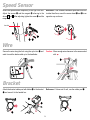
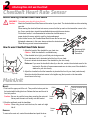
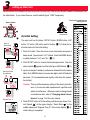
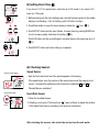
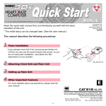
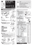
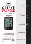
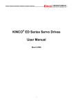
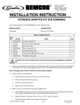
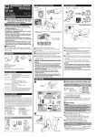
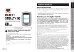
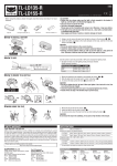
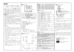
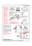
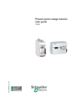
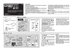
U.S. Pat. Nos. 4633216/4642606/5089775/5226340 and Pat. Pending
Copyright© 1999
CAT EYE Co.,Ltd.
MSC2DxSE-990705 1
Printed in Japan
0687511
Read this quick-start manual first, and familiarize yourself with the basic
operation of the unit.
* The initial setup can be changed later. (See the user manual.)
This manual describes the following procedures:
1
Parts Installation
* If you already have CAT EYE Cyclocomputer (Model CCMT300, ED200, ST300 and AT100), you can use the
same bracket and sensor; so you do not need parts
installation. Just attach the 2Dx attachment on your
bracket.
2
3
4
PUSH
2Dx attachment
Attaching Main Unit and Chest Belt
Setting up Main Unit
Other Important Features
E
For more detailed setup and operations, please read
the user manual.
2-8-25, Kuwazu, Hihashi Sumiyoshi-ku, Osaka 546-0041 Japan
Service & Research Address for United States Consumers:
CAT EYE Service & Research Center
1705 14 th St. 115 Boulder CO 80302
Phone: 303-443-4595
FAX: 303-473-0006
Toll Free: 800-5 CAT EYE
URL: http://www.cateye.com
-1-
1
Parts Installation
Parts Names
Make sure that the following parts are included in the package.
2Dx attachment
1 Bracket (Includes 2Dx attachment)
2 Speed Sensor
3 Sensor Band A (L/S)
7 Bracket Rubber Pad
4 Sensor Band B
8 Bracket Rubber Pad with Holder
5 Nylon Ties
9 Screw
6 Sensor Rubber Pad
0 Wheel Magnet
Important
A
B
2
marking line
0
The clearance between the sensor 2 and the magnet 0 should
be about 5mm.
Align the center of the magnet 0
and the sensor’s marking line while
rotating the wheel.
Entire View
Magnet
Use a coin to attach the magnet 2 temporarily to the right side spoke of front wheel.
spoke
0
-2-
Speed Sensor
Attach the speed sensor temporarily to the right front fork.
Adjust the sensor 2 and the magnet 0 referring to the
above A and B . After adjusting, tighten the screw 9 and the
magnet 0.
Reference: If the clearance between spoke and front fork
is wider than 5mm, mount the sensor band 3 and 4 in an
opposite way as shown.
front fork
Wire
Secure the wire along the fork using the nylon ties 5 and
wind it round the brake cable up to the handlebar.
Caution: Allow enough wire clearance in the area marked
with .
Bracket
Attach the bracket rubber pad with holder 8 to the bracket
1 and mount it to the handle bar.
Reference: If it does not fit well, use the rubber pad 7.
-3-
2
Chestbelt Heart Rate Sensor
Attaching Main Unit and Chest Belt
Before Wearing Chestbelt Heart Rate Sensor
WARNING!! Pacemaker users should not use this unit.
Caution:
Attach the Chestbelt Heart Rate Sensor at the center of your chest. The electrode belts must be contacting
your skin.
When wearing the chest belt heart rate sensor, ensure that the top mark on the transmitter comes to the
top. If worn upside down, signal’s transmittable distance might become shorter.
For the best results, it is recommended to moisten the electrode areas, or
smear electrolytic cream, which is used for electrocardiograph.
If skin irritation occurs, the Chestbelt Heart Rate Sensor can be worn over
lightweight underwear; in this case, always moisten the electrode areas.
Chest hair may prevent correct measurement.
How to wear Chestbelt Heart Rate Sensor
1 Attachment Belt
2 Electrode Belt
3 Transmitter
1. Adjust the length of the chestbelt to your chest size.
Caution: Wear the chestbelt in comfortable way.
If the chestbelt is too tight, you will feel pain during exercise.
2. Hook attachment belt to electrode belt at the front of your chest.
Be sure to attach electrode area of the chestbelt to your skin closely.
TOP
MSC Wireless Heart Rate Sensor
Reference: If you wear the chestbelt indirectly on the skin, moisten the electrode area for the
best results. Dry skin will cause measurement error in winter, even if the chestbelt is
attached to your skin directly.
TOP
MSC Wireless Heart Rate Sensor
Top mark
3. Adjust the chestbelt so that the transmitter is placed at the front of your chest (under breast).
Wear the chest belt heart rate sensor in the legible way (the top mark on the transmitter
should come to the top).
MainUnit
Mount:
PUSH
1. First hook the upper part of the unit. Then push the bottom part into
the bracket while holding the lever. Release the lever and the unit is
fixed into position.
Caution: Be sure to push the lever when mounting the main unit.
Never press the main unit forcibly onto the bracket.
Release
Lever
2. Wind the wristband round the handlebar.
Caution: When riding, do not touch the lever; the main unit might
fall off.
Remove
Release
Lever
Remove:
To remove the main unit, unwind the wristband and push the lever.
-4-
Hook
How to mount the unit to
bicycle
3
Setting up Main Unit
Input the wheel circumference of your bicycle into the main unit. Find out your bicycle’s wheel circumference from
the table below. If you cannot fine one, use the default figure “ 2096” temporarily.
The tire size is marked on the
side of your tire.
Name of Button
wheel
circumference
(1) Initial Setting
!-1
The main unit has 6 buttons: SET/AT button, MODE button, LAP
Select a
Speed Scale
button, LT button, S/S button and AC button. (! -1) Follow the instruction below for the initial setting.
1. Push AC button. Then the entire screen illuminates and gives a
beep sound. Speed scale “km/h” flashes. Push the MODE button
to switch between “km/h” and “mph”. (! -2)
!-2
2. Push SET/AT button to choose the desired speed scale. Then the
wheel symbol
appears and the initial figure 2096 flashes. (! -3)
3. Input your bicycle’s wheel circumference obtained from the above
Setting the Wheel
Circumference
table. Push MODE button to increase the digits, and LAP button to
decrease. (To increase/decrease rapidly, hold down the respective button.)
Caution: This is just the temporary setting of the wheel circumfer!-3
ence. For more accurate measurement, input the exact
wheel circumference. When you want to change wheel
circumference later, refer to “Changing wheel circumference” in page 13 of the user manual.
“Elapsed Time TM”
4. Push SET/AT button to fix the setting, and the screen shows “Current Speed
” in the upper display, “Heart Rate
” in the
middle display and “Elapsed Time TM” in the lower display (! -4).
Initial setting is completed.
!-4
-5-
(2) Basic Operations
Start and stop measurement
Push S/S button and the unit will start measuring “Elapsed Time TM“. At the same
time, calculation of “Trip Distance DST“ and “Average Speed AVS“ starts. The symbol
of bpm in the middle display flashes while measuring. Push S/S button again and the
unit stops measuring and calculation. "Current Speed
", "Heart Rate
", “Total
Distance ODO“, “Maximum Heart Rate MXP“ and “Maximum Speed MXS“ continue to be
measured and displayed regardless of the start/stop.
Switching Functions
The upper display always shows "Current Speed
", and the middle display always shows "Heart Rate
".
In the lower display, the selected function is displayed. Push MODE Button to switch functions of the lower
display. The functions of the lower display are divided into the Main functions and Sub functions. Each Main
function has its corresponding Sub function. To go back to Main function, push MODE button. You can not switch
the Sub function to one another.
Hold Down (2sec.)
Just Push
Clock Time
(Current Speed)
Maximum
Heart Rate
Elapsed Time
Average Speed
Maximum Speed
Trip Distance
Measurement screen map
Switching the lower display by
pushing MODE button.
Total Distance
-6-
(3) Setting Clock Time
If you chose “km/h” for speed scale, clock time is in 24h mode; if you chose “mph”,
clock is in 12h mode.
#-1
1. Before entering into the clock setting mode, see that the bpm symbol in the middle
display is not flashing. If bpm is flashing, push S/S button to stop it.
2. Push Mode button to scan the lower display to show the “
” icon. (#-1)
3. Push SET/AT button and the hour flashes. Increase them by pushing MODE button (to increase rapidly, hold down the button.) (#-2)
Push S/S button and the minute flashes. Increase them by the same way as in 3.
#-2
(#-3)
4. Push SET/AT button and clock setting is completed.
#-3
(4) Checking Sensors
Shows Current Speed
Speed Sensor
• Spin the front wheel and see if the speed appears in the display.
If the speed stays zero, the position of the speed sensor and the magnet is not
correct. Re-adjust the position so that it meets the conditions A and B in
“Bracket/Sensor installation”
Shows Heart Rate
Heart Rate Sensor
1. Wear the chestbelt sensor.
2. Stand by your bicycle. If the heart icon “
Flash
” does not flash, re-adjust the location
of the Heart Rate Sensor according to the previous instructions.
After checking the sensors, take a test ride and see how the unit works.
-7-
4
Other Important Features
The following features and operations are important when you use MSC-2Dx.
Auto time feature
When this function is on, “
” icon appears. The main unit detects the wheel rotation and
automatically starts/stops measurement. In the default state, this function is off. To switch
on/off this function, push SET/AT button when the lower display is either “Elapsed Time
TM“, “Average Speed AVS“ or “Trip Distance DST“.
Caution: When this feature is on, you cannot start/stop the measurement by button operation. Therefore this feature is useful only when riding bicycle. When you
use this unit on your wrist as a heart rate monitor, turn off the Auto time feature.
Changing Upper Display
In the Default State the upper display always shows "Current Speed
". However, you
can change it to Clock, by pressing SET/AT button and S/S button simultaneously (in this
case "Current speed
" comes down to the lower display and joins in the main function).
*When Auto function is on, just push S/S button and the upper display changes from
"Current speed
" to "Clock time ".
Reset Operation
To reset the data of “Elapsed Time TM“, “Average Speed AVS“, “Maximum Speed MXS“,
“Maximum Heart Rate MXP“ and “Trip Distance DST“, push S/S button and MODE button
simultaneously.
Pace Arrow
When you are using the unit for cycling, the pace arrow appears in the right side of the
lower display. The pace arrow indicates whether the current speed is higher or lower than
the average speed. When the average speed is zero, no arrow appears.
Power Saving Feature
When the main unit is left without receiving any signal or there is no button operation for
about 15 minutes, power is shut down and the unit will be in “sleep” state, displaying only
clock. By receiving signal from the wheel, or by a press of any button other than LT button,
the screen returns to normal.
LT button
When you push this button, the screen will illuminate for 3 seconds.
MSC-2Dx provides you various functions such as “Record memory feature” and “Heart
rate target zone”. For more detail of these functions, read the user manual.
-8-