1
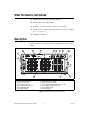
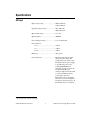
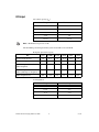
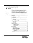
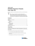
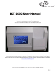
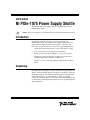
USER GUIDE
NI PXIe-1075 Power Supply Shuttle
The NI PXIe-1075 power supply shuttle is a replacement part for the
NI PXIe-1075 chassis.
Caution
This power supply is not compatible with any other National Instruments chassis.
Introduction
To minimize downtime caused by a power-supply failure, the
NI PXIe-1075 chassis has a modular power supply shuttle. This power
supply shuttle includes the chassis power supply, cooling fans, and
fan-control circuitry. Key features of the power supply shuttle include:
•
Universal AC input with automatic voltage and frequency ranging
•
Over-current protection via push-reset circuit breaker
•
Remote power monitoring and inhibit via a rear-panel connector
•
Temperature-sensing module that can adjust fan speed based on
air-intake temperature to minimize audible noise
•
Circuitry to control a front-panel LED that indicates power supply
failure
Unpacking
Carefully inspect the shipping container and the power supply shuttle for
damage. Check for visible damage to the metal work. Check to make sure
all handles, hardware, and switches are undamaged. Visually inspect the
inside of the shuttle for any possible damage, debris, or detached
components. If damage appears to have been caused during shipment, file
a claim with the carrier. Retain the packing material for possible inspection
and/or reshipment.
What You Need to Get Started
❑ NI PXIe-1075 chassis (the unit being repaired)
❑ NI PXIe-1075 power supply shuttle
❑ Read Me First: Safety and Electromagnetic Compatibility
❑ NI PXIe-1075 User Manual (provided with the chassis; also available
at ni.com/support)
❑ #1 Phillips screwdriver
Description
Refer to Figure 1 to locate user-accessible components on the power supply
shuttle.
3
4
6
5
7
8
9
10
2
11
1
12
4
1
2
3
4
5
6
7
Universal AC Input
Push-Reset Circuit Breaker
Chassis Ground Screw
Air Filter Retainer Screws
Power Supply Shuttle ID Label
10 MHz REF OUT BNC
10 MHz REF IN BNC
14
8
9
10
11
12
13
14
13
Remote Inhibit and Voltage Monitoring Connector
Inhibit Mode Selector Switch
Fan Speed Selector Switch
Power Supply Shuttle Mounting Screws (10x)
Power Supply Shuttle Handle (2x)
Power Supply Shuttle
Air Filter Retainer
Figure 1. Rear View of the NI PXIe-1075 Chassis
NI PXIe-1075 Power Supply Shuttle User Guide
2
ni.com
Installation and Maintenance
The information in this section is for qualified service personnel only. Read
the Read Me First: Safety and Electromagnetic Compatibility document
included with your kit before using the power supply shuttle.
Many components within the chassis under repair are susceptible to static
discharge damage. Service the chassis only in a static-free environment. Observe standard
handling precautions for static-sensitive devices while servicing the chassis. Always wear
a grounded wrist strap, or equivalent, while servicing the chassis.
Caution
Caution
Always disconnect the AC power cable before cleaning or servicing the chassis.
Never connect the AC power cable to the power supply shuttle until you install it
in a chassis. Do not use, test, or configure the power supply shuttle outside of a chassis.
Caution
The power supply shuttle is a replacement part for the NI PXIe-1075
chassis. The NI PXIe-1075 User Manual contains all of the most up-to-date
chassis service procedures, including removal and replacement of power
supply shuttles. The chassis includes a hardcopy of the user manual;
additionally, you can download a softcopy from ni.com/support.
Removal
Before attempting to replace the power supply shuttle, verify that there is
adequate clearance behind the chassis. With the chassis powered off,
disconnect the power cable from the power supply shuttle on the back of
the chassis. Identify the ten mounting screws that attach the power supply
shuttle to the chassis. Refer to Figure 1 for the mounting screw locations.
Using a Phillips screwdriver, remove the mounting screws. Pull on the
two rear handles of the power supply shuttle to remove it from the back of
the chassis.
Installation
Ensure that there is no visible damage to the new power supply shuttle.
Verify that the housing and connector on the new power supply shuttle
have no foreign material inside. Remove the protective cap on the
PXI_CLK10 connector. Install the new power supply shuttle into the
opening on the rear of the chassis. Install and tighten the ten mounting
screws with a Phillips screwdriver.
© National Instruments Corporation
3
NI PXIe-1075 Power Supply Shuttle User Guide
Configuration
The fan-speed selector switch is on the rear panel of the power supply
shuttle. Refer to Figure 1 to locate the fan-speed selector. Select HIGH for
maximum cooling performance (recommended) or AUTO for quieter
operation. When set to AUTO, air-intake temperature determines the fan
speed.
The power supply shuttle will not power up unless connected to the backplane in a
functional NI PXIe-1075 chassis.
Note
Power Cord
For 100–120 VAC installation, use gray power cords rated for 125 V/15 A,
using the NI cable part numbers listed in the following table.
Country
NI Part Number
North America
763830-01
Japan
763841-01
Connecting Safety Ground
The power supply shuttle is designed with a three-position NEMA 5-15
(IEC 60320) jack that connects the ground line to the chassis ground. To minimize
shock hazard, make sure the electrical power outlet you use to power the chassis has
an appropriate earth safety ground.
Caution
If your power outlet does not have an appropriate ground connection, you
must connect the premise safety ground to the chassis grounding screw.
Refer to Figure 1 to locate the chassis grounding screw. To connect the
safety ground, complete the following steps:
1.
Connect a 16 AWG (1.3 mm) wire to the chassis grounding screw
using a grounding lug. The wire must have green insulation with a
yellow stripe or must be noninsulated (bare).
2.
Attach the opposite end of the wire to permanent earth ground using
toothed washers or a toothed lug.
NI PXIe-1075 Power Supply Shuttle User Guide
4
ni.com
Specifications
AC Input
Input voltage range................................. 100 to 120 VAC,
220 to 240 VAC
Operating voltage range1 ........................ 90 to 120 VAC,
200 to 264 VAC
Input current rating................................. 12 A, 6 A
Input frequency ...................................... 50/60 Hz
Over-current protection.......................... 15 A circuit breaker
Line regulation
3.3 V................................................ <±0.2%
5 V................................................... <±0.1%
±12 V .............................................. <±0.1%
Efficiency ............................................... 70% typical
Power disconnect ................................... The AC power cable provides
main power disconnect. The
front-panel power switch causes
the internal chassis power supply
to provide DC power to the
CompactPCI/PXI Express
backplane. You also can use the
rear-panel D-SUB 9-pin
connector and power mode switch
to control the internal chassis
power supply. For more
information, refer to the Inhibit
Mode Switch section of Chapter 2,
Installation and Configuration, in
the NI PXIe-1075 User Manual.
1
The operating range is guaranteed by design.
© National Instruments Corporation
5
NI PXIe-1075 Power Supply Shuttle User Guide
DC Output
DC current capacity (IMP)
Voltage
Maximum Current
+3.3 V
61 A
+5 V
56 A
+12 V
62 A
–12 V
4A
5 VAUX
1.5 A
Notes Maximum total power is 791 W.
The maximum power dissipated in the system slot should not exceed 140 W.
Backplane pin current capacity
Slot
+5 V
V (I/O)
+3.3 V
+12 V
–12 V
5 VAUX
System Controller Slot
9A
0A
9A
11 A
0A
1A
System Timing Slot
0A
0A
3A
2A
0A
1A
Hybrid Peripheral Slot with
PXI-1 Peripheral
6A
5A
6A
1A
1A
0A
Hybrid Peripheral Slot with
PXI-5 (PXI Express) Peripheral
0A
0A
3A
2A
0A
1A
PXI-1 Peripheral Slot
6A
11 A
6A
1A
1A
0A
Load regulation
NI PXIe-1075 Power Supply Shuttle User Guide
Voltage
Load Regulation
+3.3 V
<5%
+12 V
<5%
+5 V
<5%
–12 V
<5%
6
ni.com
Maximum ripple and noise (20 MHz bandwidth)
Voltage
Maximum Ripple and Noise
+3.3 V
50 mVpp
+12 V
120 mVpp
+5 V
50 mVpp
–12 V
120 mVpp
Over-current protection.......................... All outputs protected from short
circuit and overload with
automatic recovery
Over-voltage protection
3.3 V and 5 V ......................................... Clamped at 20 to 30% above
nominal output voltage
Power supply shuttle MTTR .................. Replacement in under 5 minutes
Where to Go for Support
The National Instruments Web site is your complete resource for technical
support. At ni.com/support you have access to everything from
troubleshooting and application development self-help resources to email
and phone assistance from NI Application Engineers.
A Declaration of Conformity (DoC) is our claim of compliance with the
Council of the European Communities using the manufacturer’s
declaration of conformity. This system affords the user protection for
electromagnetic compatibility (EMC) and product safety. You can obtain
the DoC for your product by visiting ni.com/certification. If your
product supports calibration, you can obtain the calibration certificate for
your product at ni.com/calibration.
© National Instruments Corporation
7
NI PXIe-1075 Power Supply Shuttle User Guide
National Instruments corporate headquarters is located at
11500 North Mopac Expressway, Austin, Texas, 78759-3504.
National Instruments also has offices located around the world to help
address your support needs. For telephone support in the United States,
create your service request at ni.com/support and follow the calling
instructions or dial 512 795 8248. For telephone support outside the United
States, contact your local branch office:
Australia 1800 300 800, Austria 43 662 457990-0,
Belgium 32 (0) 2 757 0020, Brazil 55 11 3262 3599,
Canada 800 433 3488, China 86 21 5050 9800,
Czech Republic 420 224 235 774, Denmark 45 45 76 26 00,
Finland 358 (0) 9 725 72511, France 01 57 66 24 24,
Germany 49 89 7413130, India 91 80 41190000, Israel 972 3 6393737,
Italy 39 02 41309277, Japan 0120-527196, Korea 82 02 3451 3400,
Lebanon 961 (0) 1 33 28 28, Malaysia 1800 887710,
Mexico 01 800 010 0793, Netherlands 31 (0) 348 433 466,
New Zealand 0800 553 322, Norway 47 (0) 66 90 76 60,
Poland 48 22 3390150, Portugal 351 210 311 210, Russia 7 495 783 6851,
Singapore 1800 226 5886, Slovenia 386 3 425 42 00,
South Africa 27 0 11 805 8197, Spain 34 91 640 0085,
Sweden 46 (0) 8 587 895 00, Switzerland 41 56 2005151,
Taiwan 886 02 2377 2222, Thailand 662 278 6777,
Turkey 90 212 279 3031, United Kingdom 44 (0) 1635 523545
National Instruments, NI, ni.com, and LabVIEW are trademarks of National Instruments Corporation.
Refer to the Terms of Use section on ni.com/legal for more information about National
Instruments trademarks. Other product and company names mentioned herein are trademarks or trade
names of their respective companies. For patents covering National Instruments products, refer to the
appropriate location: Help»Patents in your software, the patents.txt file on your media, or
ni.com/patents.
© 2008 National Instruments Corporation. All rights reserved.
372539A-01
Jul08