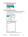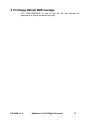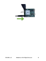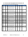
1
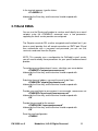
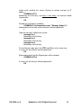
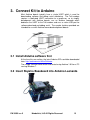
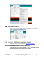
Skywire™ Development Kit User Manual NimbeLink, LLC Revised: March 2014 PN 30005 rev 5 NimbeLink, LLC All Rights Reserved. 1 1. INTRODUCTION ............................................................................................................................................ 3 1.1 1.2 1.3 1.4 2. CONNECT TO KIT USING A PC ........................................................................................................................ 5 2.1 2.2 2.3 2.4 2.5 2.6 2.7 2.8 2.9 2.10 2.11 2.12 2.13 2.14 2.15 3. UNPACK KIT CONTENTS ......................................................................................................................................... 5 ATTACH ANTENNA TO BASEBOARD .......................................................................................................................... 6 ENSURE HEADER J6 IS SHORTED WITH 2 PIN JUMPER ................................................................................................... 6 PLUG IN 12V POWER SUPPLY TO CONNECTOR J15 ..................................................................................................... 7 PLUG USB CABLE INTO CONNECTOR J14 AND PC .......................................................................................................7 PRESS AND HOLD BUTTON S1 FOR >1 SECOND ...........................................................................................................8 OPEN TERA TERM OR SIMILAR TERMINAL EMULATOR................................................................................................... 8 TEST SERIAL COMMUNICATION ............................................................................................................................... 9 TEST NETWORK COMMUNICATION .......................................................................................................................... 9 ACTIVATE MODEM (ONE-TIME STEP) ................................................................................................................... 9 SEND MODEM ACTIVATION STRING .................................................................................................................... 9 SEND SMS MESSAGE ..................................................................................................................................... 10 RECEIVE SMS MESSAGES................................................................................................................................ 10 DELETE RECEIVED SMS MESSAGE .................................................................................................................... 10 SEND EMAIL................................................................................................................................................ 11 CONNECT KIT TO ARDUINO......................................................................................................................... 13 3.1 3.2 3.3 3.4 3.5 3.6 3.7 3.8 3.9 3.10 3.11 3.12 3.13 4. ORDERABLE PART NUMBERS .................................................................................................................................. 3 ADDITIONAL RESOURCES........................................................................................................................................ 3 PRODUCT OVERVIEW ............................................................................................................................................ 3 BLOCK DIAGRAM.................................................................................................................................................. 4 INSTALL ARDUINO SOFTWARE FIRST ....................................................................................................................... 13 INSERT SKYWIRE BASEBOARD INTO ARDUINO LEONARDO ........................................................................................... 13 ENSURE HEADER J6 IS OPEN, REMOVE 2 PIN JUMPER ............................................................................................... 14 PLUG IN 12V POWER SUPPLY TO CONNECTOR J15 ................................................................................................... 14 PLUG USB CABLE INTO ARDUINO LEONARDO AND PC ............................................................................................... 14 LAUNCH THE ARDUINO APPLICATION ..................................................................................................................... 14 SELECT ARDUINO LEONARDO BOARD ...................................................................................................................... 14 SELECT SERIAL PORT ........................................................................................................................................... 15 OPEN THE SMS SEND EXAMPLE SKETCH ...............................................................................................................15 CHANGE DESTINATION PHONE NUMBER ............................................................................................................15 UPLOAD AND RUN THE SKETCH ........................................................................................................................ 16 OPEN DEBUG SERIAL MONITOR ....................................................................................................................... 16 CHANGE DEFAULT SMS MESSAGE .................................................................................................................... 17 CONNECT KIT TO OTHER DEVELOPMENT KIT .............................................................................................. 18 4.1 4.2 4.3 ENSURE HEADER J6 IS OPEN, REMOVE 2 PIN JUMPER ............................................................................................... 18 PLUG IN 12V POWER SUPPLY TO CONNECTOR J15 ................................................................................................... 18 CONNECT OTHER DEVELOPMENT KIT TO CONNECTOR J8 ............................................................................................ 20 PN 30005 rev 5 NimbeLink, LLC All Rights Reserved. 2 1. Introduction 1.1 Orderable Part Numbers Orderable Device Description Carrier Network Type NL-SWDK-1xRTT-V Skywire Development Kit, includes NL-SW-1xRTT-V Verizon CDMA 1xRTT NL-SWDK-EVDO-V Skywire Development Kit, includes NL-SW-EVDO-V Verizon CDMA EVDO 1.2 Additional Resources The following documents or documentation resources are referenced within this document. Telit’s CE910 Hardware User Guide Telit’s DE910 Hardware User Guide 1.3 Product Overview The Skywire™ Development Kit includes one Skywire™ cellular modem, baseboard, antenna, power supply, and debug cables. The kit enables you to develop your application directly on the Skywire™ modem with three different ways to connect: Connect your PC to the x910 modem UART port via onboard USB-to-UART converter and send AT commands directly to the modem through PC terminal applications. The baseboard is an Arduino shield, so you can plug the module directly onto an Arduino microcontroller. (Kit includes sample sketches showing how to initialize the modem, make data connections, and send and receive SMS messages.) To connect the kit to a different processor or development kit, a 14-pin header breaks out the necessary signals for easy connection to any device. The modem supports I/O levels from 1.65-5.5V, simplifying connection to other systems. PN 30005 rev 5 NimbeLink, LLC All Rights Reserved. 3 1.4 Block Diagram PN 30005 rev 5 NimbeLink, LLC All Rights Reserved. 4 2. Connect to Kit using a PC This section covers how to connect your development kit to a PC and provision the modem with your cellular plan. It also covers how to communicate over the serial port to the Telit x910 modem which only requires the use of USB port and connector marked J14 or USB2 in the diagram below. USB1 (connector J5) is used for Telit firmware updates to the modem and is not used in this section. 2.1 Unpack Kit Contents Note: Photo depicts modem removed from baseboard, however, modem ships pre-mounted to baseboard for ease of assembly. PN 30005 rev 5 NimbeLink, LLC All Rights Reserved. 5 2.2 Attach Antenna to Baseboard Antenna screws onto SMA connector with a clockwise rotation 2.3 Ensure header J6 is shorted with 2 pin Jumper PN 30005 rev 5 NimbeLink, LLC All Rights Reserved. 6 2.4 Plug in 12V Power Supply to connector J15 2.5 Plug USB cable into connector J14 and PC PN 30005 rev 5 NimbeLink, LLC All Rights Reserved. 7 2.6 Press and hold button S1 for >1 second Note: LEDs D1 on baseboard and D1 on module flash ON momentarily. 2.7 Open Tera Term or similar terminal emulator If you do not have a terminal emulator program, you can get Tera Term here: http://logmett.com/index.php?/download/tera-term-479-freeware.html Your PC may have multiple COM ports. Select appropriate USB COM port to communicate with the development kit. Serial Settings should be as follows: Baud Rate: 115,200 bps Data: 8bit Parity: none Stop: 1bit Flow Control: none PN 30005 rev 5 NimbeLink, LLC All Rights Reserved. 8 2.8 Test Serial Communication In the terminal program, type the letters: AT followed by the Enter key, and the terminal should respond with: OK 2.9 Test Network Communication In the terminal program, type the letters: AT+CREG? followed by the Enter key, and the terminal should respond with: +CREG: 0,1 or +CREG: 0,5 For all other responses, review network status responses online. 2.10 Activate Modem (one-time step) The cellular module included in the kit does not have an active cellular plan. NimbeLink provides reduced rate Verizon M2M data plans for Skywire products. To activate a data plan, send an email to [email protected] with your name, a phone number to contact you, and a list of all MEIDs you would like to activate. A NimbeLink staff member will call you to activate the modules real-time. 2.11 Send Modem Activation String In the terminal program, type the letters: ATD*22899; followed by the Enter key, and the module will begin the activation process which can take several minutes. The terminal should respond with: OK #OTASP: 0 #OTASP: 1 #OTASP: 2 NO CARRIER For all other responses, review network status responses online. Reset power, and repeat steps 2.4 through 2.9 before moving on to step 2.12. PN 30005 rev 5 NimbeLink, LLC All Rights Reserved. 9 2.12 Send SMS Message In the terminal program, type the letters: AT+CMGF=1 followed by the Enter key, and the terminal should respond with: OK Substitute the destination phone number for the example 5554443333. Then type: AT+CMGS=”+15554443333” followed by the Enter key, and the terminal should respond with: > At this point you can type a custom message (keep to less than 160 characters). To send the message, press the CTRL and Z keys at the same time. If successful, the terminal should respond with: +CMGS: xx 2.13 Receive SMS Messages In the terminal program, type the letters: AT+CMGF=1 followed by the Enter key, and the terminal should respond with: OK Then type: AT+CMGL="REC UNREAD” followed by the Enter key, If the terminal responds with OK then there are no messages. Otherwise, the terminal responds with the first message in the form: +CMGL=index, message_status, address, [address_text], [time_stamp] [,address_type, body_length] <CR> <LF> sms_message_body[<CR> <LF> +CMGL: ...] This is an example: +CMGL: 0,"REC UNREAD","555444333","",20130925202238 SMS message 2.14 Delete Received SMS Message PN 30005 rev 5 NimbeLink, LLC All Rights Reserved. 10 In the terminal program, type the letters: AT+CMGD=1,4 followed by the Enter key, and the terminal should respond with: OK 2.15 Send EMAIL You can use the Skywire cell modem to send an email directly to an email recipient using the AT#EMAILD command once a few parameters regarding the email service provider are configured. The Skywire cannot do SSL or other encrypted email methods but if you have an email provider that will accept connection on SMTP port 25 and then authenticate with a username and password, you can use that service to send email from the Skywire. NOTE: This example uses a configuration for GoDaddy's email service you will need to modify these parameters for your specific outbound email provider. To configure your outbound email server, substitute your server below: AT#ESMTP="smtpout.secureserver.net" followed by the Enter key, and the terminal should respond with: OK Substitute the email address you want the email to be From:. AT#EADDR="[email protected]" followed by the Enter key, and the terminal should respond with: OK Provide your email login to your account, in our example, secureserver.net AT#EUSER="[email protected]" followed by the Enter key, and the terminal should respond with: OK Provide the password for the account AT#EPASSW="myaccountpassword" followed by the Enter key, and the terminal should respond with: OK Save the email configuration: AT#ESAV PN 30005 rev 5 NimbeLink, LLC All Rights Reserved. 11 Initiate email sending; this causes Skywire to activate and get an IP address: AT#EMAILACT=1 followed by the Enter key, and after a short delay, the terminal should respond with: OK Provide the email details and body: AT#EMAILD="[email protected]","Message Subject",0 followed by the Enter key, and the terminal should respond with: > Type the message, multiple lines are ok: message line 1 followed by the Enter key message line 2 followed by the Enter key message line 3 followed by the Enter key To send the message, press the CTRL and Z keys at the same time. If successful, the terminal should respond with: OK Stop sending email and the Skywire goes off the network: AT#EMAILACT=0 If successful, the terminal should respond with: OK PN 30005 rev 5 NimbeLink, LLC All Rights Reserved. 12 3. Connect Kit to Arduino Most Arduino boards typically have a single UART which is used for downloading software and debug serial monitoring. The Telit modem requires a dedicated UART connection to a processor, so to simplify development with Arduino boards, use an Arduino Leonardo which dedicates the UART to the Telit modem and uses a native USB port for software download and debug serial. The sample sketches provided are intended for use with Arduino Leonardo development boards. 3.1 Install Arduino software first At the time this was written, the latest Arduino IDEs could be downloaded here: http://arduino.cc/en/Main/Software The sample sketches were written and tested using Arduino 1.0.5 on a PC running Windows 7. 3.2 Insert Skywire Baseboard into Arduino Leonardo PN 30005 rev 5 NimbeLink, LLC All Rights Reserved. 13 3.3 Ensure header J6 is OPEN, remove 2 pin Jumper 3.4 Plug in 12V Power Supply to connector J15 3.5 Plug USB cable into Arduino Leonardo and PC The Arduino Leonardo gets its power from the USB port and does not require an external power supply. 3.6 Launch the Arduino Application 3.7 Select Arduino Leonardo board In the ‘Tools’ drop down, select ‘Board’, then select ‘Arduino Leonardo’. PN 30005 rev 5 NimbeLink, LLC All Rights Reserved. 14 3.8 Select Serial Port In the ‘Tools’ drop down, select ‘Serial Port’, then select your COM port. 3.9 Open the ‘SMS Send’ example Sketch The sketch can be downloaded from the Skywire product page. 3.10 Change Destination Phone Number Find “DESTINATION_PHONE_NUMBER” on line 18 and edit the example phone number to the target recipient’s phone number. PN 30005 rev 5 NimbeLink, LLC All Rights Reserved. 15 3.11 Upload and Run the Sketch 3.12 Open Debug Serial Monitor When the application has finished uploading, your PC may make a noise indicating that the USB port has disconnected, then regained connection. Once connected, you can open the Serial Monitor by selecting: ‘Tools’ and then ‘Serial Monitor’ The monitor should show something like this: And the recipient should receive the default SMS message. PN 30005 rev 5 NimbeLink, LLC All Rights Reserved. 16 3.13 Change Default SMS message Find “SMS_MESSAGE” on line 20 and edit the text between the parenthesis to change the default message. PN 30005 rev 5 NimbeLink, LLC All Rights Reserved. 17 4. Connect Kit to other Development Kit The Skywire™ development kit can be connected to other embedded development kits via 14-pin connector J8. If modem USB signals are also required, they are available via USB Mini-B connector J5. 4.1 Ensure header J6 is OPEN, remove 2 pin Jumper 4.2 Plug in 12V Power Supply to connector J15 This step is important because the only way to power the Skywire™ embedded cellular modem is through the onboard power supply. If you want to power with your own power supply, you can do so by removing resistor R4 (near J2), and applying a voltage to pin 2 of header J2. PN 30005 rev 5 NimbeLink, LLC All Rights Reserved. 18 PN 30005 rev 5 NimbeLink, LLC All Rights Reserved. 19 4.3 Connect other Development Kit to Connector J8 4.3.1 Connector J8 Pin Out and Recommended Ratings Pin Name Direction Description Min Controls HW_SHUTDOWN input on Telit X910 modem, tie low for 800mS to activate. Internally pulled up to VCC with 57k resistor. Drive with open collector output. Assert only in an emergency as the module will not gracefully exit the cellular network when asserted. Modem On/Off signal. Assert low for at least 1 second and then release to activate start sequence. Drive with open collector output. Internally pulled up to internal I/O rail with 200k pull up. Do not use any external pull ups. Programmable GPIO_02 on Telit x910 modem module This is a regulated power supply from the baseboard. Other development kit could be powered from this pin if current draw is <1Amp. Programmable GPIO_03 on Telit x910 modem module 1 RESET_nIN Input 2 ON_OFF Input 3 DIO2 I/O 4 4V0 Output 5 DIO3 I/O 6 DIN Input UART data in, I/O level tied to VREF 7 ADC1 Input ADC_IN1 input on Telit x910 modem module (12bit resolution, <1mV, input resistance 1Mohm) 8 GND Input Ground Pin 9 RTS Input Modem Request to Send hardware flow control input VREF0.4V 10 DOUT Output UART data out, I/O level tied to VREF <0.55V 11 CTS Output 12 VREF Input 13 DTR Input 14 ON/nSLEEP Output PN 30005 rev 5 Typical Max VREF No Connection 0 1.8V Must be implemented. 0 1.8V No connection 4.0V No connection 0 1.8V No connection VREF0.4V VREF Must be implemented 0 1.2V No connection Must be implemented 0 Modem Clear to Send hardware flow control output Voltage reference for offboard I/O signals. This signal drives the input voltage side of an onboard buffer which converts all external I/O voltage from VREF range to 1.8V range to drive the onboard Telit x910 modem module Modem Data Terminal Ready input Signal drives the onboard LED indicating network status. OFF = Device OFF, Fast blink = Searching for Network & Not Registered, Slow Blink = Regsitered with full service, Permanently on = call is active. See Telit x910 modem manual for additional information. If not used VREF VREF x 0.67 VREF x 0.67 <0.55V Must be implemented No connection 5.5V Must be implemented VREF0.4V VREF Tie to GND 0 1.8V No connection 1.65V 1.8V or 3.3V Tie to GND NimbeLink, LLC All Rights Reserved. 20