1
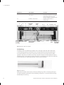
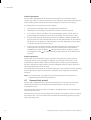
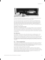
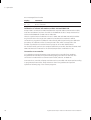
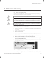
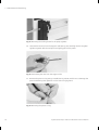
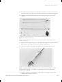
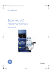
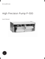
GE Healthcare
High Precision Pump P-500
User Manual
Important user information
All users must read this entire manual to fully understand the
safe use of High Precision Pump P-500.
WARNING!
The WARNING! sign highlights instructions that must
be followed to avoid personal injury. It is important
not to proceed until all stated conditions are met and
clearly understood.
CAUTION!
The Caution! sign highlights instructions that must be followed
to avoid damage to the product or other equipment. It is
important not to proceed until all stated conditions are met and
clearly understood.
Note
The Note sign is used to indicate information important for
trouble-free and optimal use of the product.
CE Certifying
This product meets the requirements of applicable CE-directives.
A copy of the corresponding Declaration of Conformity is
available on request.
The CE symbol and corresponding declaration of conformity, is
valid for the instrument when it is:
– used as a stand-alone unit, or
– connected to other CE-marked GE Healthcare instruments, or
– connected to other products recommended or described in
this manual, and
– used in the same state as it was delivered from GE Healthcare
except for alterations described in this manual.
WARNING!
This is a Class A product. In a domestic environment this product
may cause radio interference in which case the user may be
required to take adequate measures.
Recycling
This symbol indicates that the waste of electrical
and electronic equipment must not be disposed
as unsorted municipal waste and must be
collected separately. Please contact an authorized
representative of the manufacturer for information
concerning the decommissioning of equipment.
Contents
Contents
1
Introduction
2
Specifications
3
Unpacking and equipment list
4
Description
4.1 Front panel........................................................................................................................13
4.2. Rear panel .........................................................................................................................16
5
Installation
5.1
5.2
5.3
6
Operation
6.1
6.2
6.3
6.4
6.5
6.6
7
Mains installation...........................................................................................................19
Tubing connections ......................................................................................................21
Start-up procedure .......................................................................................................21
Routine operation ..........................................................................................................23
Solvents ..............................................................................................................................23
Pressure limit control ...................................................................................................24
Pulse compensation .....................................................................................................25
Pump head cleaning ....................................................................................................26
Connections to the remote control socket ........................................................26
Maintenance and servicing
7.1
7.2
Piston seal replacement .............................................................................................29
Recycling ...........................................................................................................................32
8
Trouble shooting
9
Spare parts and accessories
High Precision Pump P-500 User Manual 56-1129-73 Edition AI
5
Contents
6
High Precision Pump P-500 User Manual 56-1129-73 Edition AI
Introduction 1
1 Introduction
The High Precision Pump P-500 (Code No. 18-1003-65) is a laboratory pump for use
in liquid chromatography and other applications where constant flow at pressures up
to 4 MPa (40 bar, 580 psi) is required. Pump P-500 is very accurate and reproducible,
especially at low flow rates over the whole pressure range. The excellent chemical
resistance of the pump makes it possible to work with corrosive liquids, e.g. organic
solvents, as well as aqueous solutions.
Pump P-500 is designed to facilitate routine chromatography work. The flow rate is
easily and accurately set with a three digit thumb-wheel switch. The wide flow range
makes the pump suitable both for analytical and preparative chromatography. A unique
wash program provides fast and secure solvent change-over and a pressure limit control
protects the column from damaging pressures.
Together with the Gradient Programmer GP-250 Plus or the Liquid Chromatography
Controller LCC-501 Plus, the Pump P-500 can be used to form accurate and reproducible
gradients.
Pump P-500 is fully compatible with other equipment such as the single and dual path
UV-monitoring systems UV-M II, UV-1, and their associated recorders and with the
TM
Fraction Collectors FRAC-100, FRAC-200 and SuperFrac .
Pump P-500 is designed to work with a wide range of columns and gels supplied by
GE Healthcare.
WARNING! When using hazardous chemicals, take all suitable protective measures,
such as wearing protective glasses and gloves resistant to the chemicals used. Follow
local regulations and instructions for safe operation and maintenance of the system.
High Precision Pump P-500 User Manual 56-1129-73 Edition AI
7
1 Introduction
8
High Precision Pump P-500 User Manual 56-1129-73 Edition AI
Specifications 2
2 Specifications
Flow rate range
1–499 ml/h variable in steps of 1 ml/h.
Operating pressure
4.0 MPa (40 bar, 580 psi) up to 200 ml/h. 2.5 MPa
(25 bar, 360 psi) in the range 200–499 ml/h.
Flow rate accuracy
± 1.5% of setting or ± 0.5 ml/h (which ever
Reproducibility
Better than 0.5% set flow rate.
Flow rate precision
Better than 1% over 8 hours at 160 ml/h with the same
solvent and temperature.
Materials of wetted parts
Fluoroplastics (Kel-F, Tefzel , Teflon ), PEEK, PFE (Simriz ),
titanium and borosilicate glass.
Pressure read out
0–5.0 MPa (0-50 bar, 0–700 psi). Pressure recording 0.5 MPa
(5 bar, 70 psi)/mV.
Pressure limit
Protective shutdown, adjustable in the range 0–5.0 MPa
(0–50 bar, 0–700 psi).
Power supply, voltage
frequency
100/120/220-230/240 V~
50–60 Hz
Power consumption
32 VA
Environment
+4 to 40 ° C, 20–95% relative humidity, 84–106 kPa
(840–060 mbar) atmospheric pressure.
Dimensions
410 x 217 x 165 mm.
Weight
9 kg.
Motor
Stepper motor (110 pulses/0.1 ml).
Compliance with standards
The declaration of conformity is valid for the instrument
only if it is:
Safety standards
High Precision Pump P-500 User Manual 56-1129-73 Edition AI
TM
TM
TM
•
used in labaratory locations
•
used in the same stat as it was delivered from
GE Healthcare except for alterations described in
the User Manual.
•
connected to other CE labelled GE Healthcare modules
or other products as recommended.
This product meets the requirement of the Low Voltage
Directive (LVD) 73/23/EEC through the following harmonized
standards:
•
EN 61010-1
•
IEC 61010-1
•
CAN/CSA-C22.2 No. 61010-1
•
UL61010-1
9
2 Specifications
EMC standards
This device meets the requirements of the EMC
Directive 89/336/ EEC through the following harmonized
standards:
•
EN 61326 (emission and immunity)
•
EN 55011, GR 2, Class A (emission)
•
This device complies with part 15 of the FCC rules
(emission). Operation is subject to the following two
conditions:
1 This device may not cause harmful interference.
2 This device must accept any interference received,
including interference that may cause undesired
operation.
10
High Precision Pump P-500 User Manual 56-1129-73 Edition AI
Unpacking and equipment list 3
3 Unpacking and equipment list
Unpack Pump P-500 carefully and check the contents of the carton against the packing
list. Save the packing material and the carton in case Pump P-500 needs to be returned.
Check Pump P-500 for any visible signs of damage that may have occurred during
transit.
CAUTION! The system should be installed on a stable laboratory bench providing a
suitable working area.
Place Pump P-500 on the bench and check that it is set to the appropriate voltage
(see Section “4.2. Rear panel”). Before operating the pump carefully read Section “5.
Installation”.
High Precision Pump P-500 User Manual 56-1129-73 Edition AI
11
3 Unpacking and equipment list
12
High Precision Pump P-500 User Manual 56-1129-73 Edition AI
Description 4
4 Description
4.1
Front panel
Controls and indicators
Please refer to figure 1.
Detail No.
Description
Function
1
SET, spring-loaded push button
Pressing the button and
simultaneously turning the SET
potentiometer sets limit pressure.
Momentarily pressing the button
after pump shutdown caused by
excessive pressure, restores
operation.
2
SET, potentiometer
Sets pressure limit when used in
combination with SET pringloaded
push button.
3
LIMIT, indicator lamp
Lights up when the pump shuts
down if preset high pressure limit
is exceeded.
4
PRESSURE, MPa meter
Indicates the actual operating
pressure in the range 0–5.0 MPa
(0–50 bar). The range 4.0–5.0 MPa
is marked red and should not be
exceeded.
5
Potentiometer (screw driver
adjustable).
Adjusts the pressure output to 0.
6
Change direction, push button
Momentarily pressing the button
changes the driving direction of
the pistons. Holding the spring
loaded button depressed gives
maximum flow rate independent
of the flow rate setting.
7
PULSE COMP, push button
Pulse compensation reduces
pulses to a minimum. Especially
useful when monitoring at high
sensitivities.
8
FLOW RATE ml/h, three digit
thumb-wheel switch of
Sets flow rate. Adjustable in steps
1 ml/h in the range 1–499 ml/h.
9
RUN, indicator lamp
The lamp lights up when the
pump is in the RUN position.
10
RUN, push button
Run position
In the Run position the pump is
ready for operation, according to
the setting of the different
controls.
Standby position
In the Standby position the pump
is shutdown but is supplied with
current. Used when the pump is
to be stopped temporarily.
High Precision Pump P-500 User Manual 56-1129-73 Edition AI
13
4 Description
Detail No.
Description
Function
11
SOLVENT CHANGE,
push button
Starts a wash program to change
the previous solvent in the pump.
This control works only if the
pump is already in the RUN mode.
12
POWER, mains switch
Supplies mains power to
Pump P-500.
1
2 3
4
5 Pressure
sensor
6-port
valve
Piston
Fixing screw End Tubing
Rinsing tubing
for cylinder piece cover
connections
assembly
Protective
covers
6 7
8
Piston
9 10 11
End
piece
12
Fixing screw
for cylinder
assembly
Fig 1. Pump P-500 front panel.
Fluid delivery
Pumping action is provided by a stepper motor, through a gear box and a ball screw,
to two alternating pistons mounted on the front panel (Fig 1). The driving mechanism
is located behind the front panel. The pistons reciprocate in two high precision glass
cylinders. The pistons are driven such that one piston draws in solvent while the other is
expelling solvent. The change of piston direction is controlled by opto-electronic switches
at the end positions. These switches also control valve movement.
Fig 2. The piston.
Each piston consists of three parts: a head, a sealing ring, and a connecting rod (Fig 2).
The piston/cylinder mechanism offers durability, resistance to corrosive fluids and easy
disassembly for servicing.
14
High Precision Pump P-500 User Manual 56-1129-73 Edition AI
Description 4
Valve
The six-port valve (Fig 1) is a motorized rotary valve driven by a DC-motor through a
gear box. The function of the valve is to control the solvent flow to and from the pistons.
The valve has six tubing connections. These tubing connections and the general flow
diagram are shown in figure 3. All connections except the two labelled IN and OUT are
already fitted.
L1
OUT
L2
IN
R1
1
2
R2
1
2
Fig 3. General flow diagram.
The valve operates automatically when the pistons reach their end positions. This
is sensed by opto-electronic switches. The valve also operates when the button
(change direction) is pressed.
Pressure sensor
The pressure sensor (Fig 1) is a strain gauge bridge type which determines the back
pressure in the system. The pressure sensor consists of a diaphragm which contracts or
expands with pressure changes causing the resistance in an electronic bridge to change.
This gives a signal proportional to the back pressure. The signal is then amplified and
relayed to the pressure meter (front panel) and the pressure output (rear panel). The
pressure sensor has two main functions, the first to continuously measure the operating
pressure and the second to sense excessive pressure which could damage the columns.
If the pressure builds up to the limit set on the SET control, the pump automatically shuts
down and the red LIMIT lamp lights. Detailed instructions for setting the pressure limit
and for the connection of a recorder to the pressure output are given in Section
“6.3. Pressure limit control”.
Security cover
Pump P-500 is equipped with a security cover to protect the user from breakage of the
glass cylinders resulting from incorrect handling. The security cover is easily mounted
and dismounted by just snapping it on and off from its pressure points.
High Precision Pump P-500 User Manual 56-1129-73 Edition AI
15
4 Description
Tubing connectors
All tubings in the pump are supplied with a new type of tubing connector. Each tubing
connector consists of two parts, a nipple and a nipple screw. The tubings supplied
with the pump are preflanged but tubings of any length can also be flanged with the
Flanging/Start up Kit, Code No. 19-5079-01, 120 V, or 19-5090-01, 220 V, supplied on
request. The tubing connectors are also compatible with the GE Healthcare solvent
resistant (SR) chromatography system.
4.2.
Rear panel
See figure 4.
Voltage selector
Adapts Pump P-500 to 100, 120, 220–230 or 240 V.
Mains
Socket for mains inlet.
Fuse
This holds a 160 mA fuse for 220–230 V instruments or a 300 mA for 110 and
120 V instruments. The fuse protects the electronics from damage in the event of short
circuiting.
Pressure output
This is connected to a recorder, such as recorder REC 111 or REC 112. The recorder
can be used to plot the operating pressure (in the range 0–4.0 MPa) during any given
experimental run. The output signal from the pressure sensor is 1 mV/0.5 MPa (5 bar).
Remote control
This is a 15 pin female connector of the D-type. The numbers referred to are printed on
the connector.
Note: All outputs must have an external pull-up resistor (2–10 KΩ ) to + 5V.
16
High Precision Pump P-500 User Manual 56-1129-73 Edition AI
Description 4
4
3
1
2
Fig 4. The rear panel. 1. Voltage selector 2. Mains socket 3. Pressure output 4.
Remote socket
Outputs TTL open collector, 5V
Direction of piston’s movement (pin 4)
1=left
0=right
Pump occupied (pin 9)
1=OK
0=occupied
The pump is “occupied” during the following activities: wash program, valve
change, too low mains voltage, standby position or pressure limit shutdown.
Shutdown due to error (pin 10)
1=error
0=OK
There are two possibilities for error indication, no mains voltage or pressure limit
shutdown. External control is not possible during error indication.
Actual speed (pin 13) 0–153 Hz
Ground (pin 15)
Inputs (TTL activation)
External activation of wash program (pin 1)
1=not activated
0=activated
External direction control (pin 2)
1 =not activated
0=valve switch
External RUN/STANDBY control (pin 11)
1=run
0=STANDBY
Internal/external speed control (pin 12)
1=internal
0=external
When external speed control is used (pin 14) 0-153 Hz, (pin 12) must be 0
(see above). Pins 3, 5,6,7 and 8 are not connected.
High Precision Pump P-500 User Manual 56-1129-73 Edition AI
17
4 Description
18
High Precision Pump P-500 User Manual 56-1129-73 Edition AI
Installation 5
5 Installation
5.1
Mains installation
Before conecting Pump P-500 to the mains supply, please read the following instructions
carefully.
1. There are two Mains Kits supplied (one for 100–120 V and one for 220/240). Choose
the kit appropriate to the local mains supply voltage and discard the irrelevant kit
immediately.
WARNING! Only use mains cables delivered or approved by GE Healthcare.
WARNING! Installing the wrong mains kit can endanger personal safety and cause
irreparable damage to the pump. Always connect the instrument to a properly
grounded mains outlet.
2.
3.
Remove the warning label covering the fuse/voltage selector unit on the rear panel.
Open the fuse/voltage selector cover with a thin screwdriver or the key provided
(Figs 5 and 6).
Fig 5. Opening the fuse/voltage selector cover. When using the screwdriver to open the
cover, insert it at the top centre and apply pressure.
4.
Place the fuse into the fuseholder and install it into the instrument in the right-hand
position (Fig. 7).
5.
Remove the voltage selector switch, select correct voltage and place the switch into
the instrument with the correct voltage showing (Fig 8).
Note: Use 220 V setting for 230 V mains outlet.
6.
Close the cover. The correct voltage should be visible in the window.
7.
Connect Pump P-500 to a grounded mains outlet using the cable supplied in the
Mains Kit.
WARNING! In case of an emergency situation, the mains plug must always be easy to
disconnect.
High Precision Pump P-500 User Manual 56-1129-73 Edition AI
19
5 Installation
Fig 6. Opening the fuse voltage selector cover using lateral pressure with the key provided.
Fig 7. Installing the fuseholder. Always use the hole at the righthand side when you
install the fuseholder.
Fig 8. Choose the correct voltage by turning the voltage selector.
20
High Precision Pump P-500 User Manual 56-1129-73 Edition AI
Installation 5
5.2
Tubing connections
Inlet and outlet tubings
The inlet and outlet tubings are supplied preflanged. The outlet tubing with a dimension
of 1.8 x 0.5 mm has tubing connectors attached at both ends.
The inlet tubing has a tubing connector attached at one end and a solvent filter at the
other end. The solvent filter consists of a filter holder made of fluoroplastic and a filter
insert containing a guide ring and a filter with a pore size of 2 micron. The filter is made
of polypropylene. Also supplied are 5 extra filter inserts which are for replacement when
the filter becomes blocked. The filter insert is replaced by snapping off the guide ring
and filter with a spatula or similar tool and inserting a new one. Extra filter inserts are
available on request, Code No. 19-5086-01.
Rinsing tubings
The rinsing tubing has a dimension of 3.1 x 1.1 mm. Cut two pieces of the rinsing tube
supplied to a sufficient length to reach the bottom of a rinsing solution bottle and
connect them to the rinsing tubing connections (Fig 1).
Internal tubings
The internal tubings in the pump shown in figure 3 have a dimension of 1.8 x 0.8 mm.
Worn out tubing should be replaced with the same size of tubing. A tubing kit is available
on request. Code No. 19-4434-01.
5.3
Start-up procedure
P-500 is factory tested prior to delivery. To ensure that it is functioning properly upon
start-up, the following procedure should be performed step by step.
1.
Check that the power switch (Fig 1) is set to “OFF” and plug the mains cable into the
mains inlet.
2.
Connect the inlet tubing to the connection on the right hand side of the valve
marked
and the outlet tubing to the upper connection on the pressure sensor
(see Fig 9). Tighten the tubing connectors by using the wrench supplied. Use the end
marked N.
→
outlet
inlet
Fig 9. Connection of the outlet and inlet tubing.
3.
Submerge the inlet tubing in a suitable reservoir filled with degassed distilled water.
4.
Submerge the rinsing tubing in a suitable reservoir filled with rinsing solution i.e.
20% ethanol.
High Precision Pump P-500 User Manual 56-1129-73 Edition AI
21
5 Installation
5.
Check that the button RUN (Fig 1) is released, the pump is in standby position and
turn power switch to ON.
6.
Set the pressure limit to 4.5 MPa (45 bar) by fully pressing the button SET (Fig 1) and
simultaneously turning the potentiometer SET (Fig 1) clockwise. Read the value from
the pressure meter.
7.
Start the wash program by pressing the button SOLVENT CHANGE (Fig 1) and the
button RUN.
Note: When the pump is run for the first time friction between the dry glass cylinder and
the dry sealing ring may give rise to some noise. It will however dissapear when
the parts have been wetted.
8.
When the pump stops after completion of the wash program (approximately
5 minutes), release the SOLVENT CHANGE button.
9.
The cylinder is now filled with rinsing solution behind the pump heads. Connect
the rinsing tube connections on the back of the pump heads with a short piece of
rinsing tubing. The wash liquid will now be flushed between the two cylinders when
the pump operates.
10. Run the pump until the piston heads are at the middle of their cylinders.
11. Block the solvent outlet using the stop plug supplied.
12. Set flow rate to 10 ml/h with the three digit thumbwheel switch and start fluid
delivery by releasing the button SOLVENT CHANGE. Run the pump until the back
pressure is 4.0 MPa (40 bar), indicated on the pressure meter, and check against the
following list for possible leaks.
Leakage
Action
Tubing connections
Tighten the leaking tubing connector with the
wrench supplied.
Between end piece
and glass cylinder
Tighten the two M3 nuts or change the gasket
according to Section “7.1 Piston seal replacement”
Leakage between piston
O-ring and glass cylinder.
Replace the piston O-ring according to section 7.1
13. Press the button
(change direction), the outlet is now onnected to the other
piston. Start fluid delivery and run until the back pressure is 4.0 MPa. Check for
possible leaks.
14. The pump is now ready for operation. Before changing solvent see Section
“6.2. Solvents”.
22
High Precision Pump P-500 User Manual 56-1129-73 Edition AI
Operation 6
6 Operation
6.1
Routine operation
This section is a guide for routine operation and assumes that Pump P-500 has been
installed according to the Section “5. Installation”.
WARNING! When using hazardous chemicals, take all suitable protective measures,
such as wearing protective glasses and gloves resistant to the chemicals used. Follow
local regulations and instructions for safe operation and maintenance of the system.
1.
Fill the solvent reservoir with sufficient solvent. Check that all solvent considerations
are met, check solvent miscibility if change of solvent in the pump is desired (see
Section “6.2. Solvents).
2.
Check that the button RUN is released, pump is in standby position and turn the
POWER switch to ON.
3.
Set the desired flow rate with the three digit thumbwheel switch.
4.
If change of solvent in the pump is desired, press SOLVENT CHANGE and start the
wash program by pressing RUN.
5.
Set the desired pressure limit by simultaneously pressing the button SET and turning
the potentiometer SET. The pressure limit can be changed during a run.
6.
Connect the outlet tubing to the injection valve.
7.
When monitoring at high sensitivities with a system giving a back pressure greater
than 0.5 MPa (5 bar), press PULSE COMP to activate the pulse compensation circuit.
8.
Start fluid delivery by pressing RUN, or if solvent change over has been performed
as in step 4, release the button SOLVENT CHANGE.
6.2
Solvents
Degassing and filtering
The use of filtered, degassed solvents and buffers is important for maintenance-free
operation. Particles in the solvent can block the channels in the valve, shortening its
life-time.
Degassing prevents the formation of air bubbles which can cause baseline noise and
drift. Degassing and filtering of solvents, except for solvents with low boiling points, can
be performed in a one-step procedure by filtering the solvent through a vacuum filter
(0.45 micron filter is recommended). Solvents with low boiling points, e.g. methylene
chloride, can be degassed in a sonic bath. The boiling point of the solvent should be
checked prior to degassing.
Mixing solvents
Prior to changing from one solvent to another, the miscibility of the solvents must be
determined. Change of solvents which are immiscible requires an intermediate solvent,
e.g. change from water to methanol can be made directly, while change from water to
hexane requires an intermediate step such as 2-propanol.
High Precision Pump P-500 User Manual 56-1129-73 Edition AI
23
6 Operation
Solvent changeover
Pump P-500 is equipped with an automatic wash program that facilitates solvent
change over. Valve V–7 and Motor Valve MV–7 are 3-position valves with a wash position
which enables solvent change without disconnecting the column from the pump.
To change solvent in the pump proceed as follows:
1.
Set the pump in standby position by releasing the RUN button.
2.
Submerge the inlet tubing in the new solvent reservoir (minimum 40 ml).
3.
If a V–7/MV–7 valve is included in the chromatographic system, set the valve to
position WASH. Otherwise disconnect the outlet tubing from the injection valve.
4.
Start the wash program by pressing the buttons SOLVENT CHANGE and RUN. The
previous solvent is now automatically rinsed out and replaced with the new solvent.
The duration of the program is approximately 5 minutes, depending on the position
of the pistons when the program starts.
5.
If there are any air bubbles trapped in the glass cylinders after completion of the
wash program, a quick way to remove them is to release the button SOLVENT
CHANGE and to press the button
(change direction) when the piston reaches
its end position. Press
(change direction) several times until the air bubbles are
removed.
Solvent resistance
Pump P-500 can be used with all types of buffers, detergents and organic solvents
commonly used in chromatography. In addition, most inorganic and organic acids
and bases e.g. diluted mineral acids, metal salt solutions, carboxy acids, anhydrides,
aromatic and aliphatic hydrocarbons, alcohols, aldehydes, ketones, ethers, esters and
chlorinated hydrocarbons can be used.
The following solvents should not be used in the pump: concentrated nitric acid, oxidizing
acids, organic bases, high concentrations of sulphonic acid, ethyl ether and fluoride
solutions.
Note: Do not leave acids, e.g. sulphuric acid, in the pump after use. Once the run is
completed, the acid should be washed out.
6.3
Pressure limit control
Pump P-500 is equipped with a protective pressure limit control which automatically
shuts down the pump if the back pressure should build up to the limit set on the
overpressure circuit.
The pressure limit can be set either in the RUN or standby position. To set the pressure
limit proceed as follows.
Press the button SET. The actual pressure limit is shown in the pressure meter. To change
the pressure limit, turn the potentiometer SET whilst simultaneously pressing the push
button SET (see Fig 10).
24
High Precision Pump P-500 User Manual 56-1129-73 Edition AI
Operation 6
Fig 10. Setting the pressure limit.
To check the set pressure limit during operation or in standby position, press the push
button SET and read the actual value from the pressure meter.
If the pump shuts down due to the pressure limit having been exceeded (indicated
when the red LIMIT lamp lights up), check if the column or tubings are blocked. After
the condition has been corrected, restore pump operation by momentarily pressing
the button SET. The pump does not start until the button is released. This gives an
opportunity to check the actual pressure limit and to change it if necessary before the
pump operation is restored.
Connection to the pressure output
When a plot of the operating pressure on a recorder is desired, connect the signal input
cable (Code No. 18-1115-25) into the output PRESSURE on the rear panel of the pump
(red to red and black to black) and to the recorder. Set the recorder range selector to 10
mV and adjust the recorder zero. The plotted pressure will be 5.0 MPa (50 bar, 700 psi) full
scale response.
Zero adjustment
If the pressure output does not read O when the pump is in standby position or if the
back pressure is O during run, the pressure sensor needs to be zero adjusted. The
adjustment is performed by putting a screwdriver in the hole next to the pressure meter
(see Fig 1) and turning the adjusting screw until the pressure meter reads zero. If exact
zero adjustment of the pressure sensor is required, a recorder should be connected to
the pressure output on the rear panel and the adjustment is performed until the recorder
reads zero.
6.4
Pulse compensation
When monitoring at high sensitivities with systems giving a back pressure, disturbance
of the baseline can occur when the pistons change direction. This disturbance can be
eliminated by using a pulse damper. Pump P-500 is designed with a pulse compensation
circuit which operates when the button PULSE COMP is pressed.
The principle for pulse compensation is as follows:
Without pulse compensation, piston A reaches its end position and the operating
pressure starts to decrease as the valve starts to switch. No flow is delivered from the
pump during this time period. When the piston B is connected to the outlet the operating
pressure is momentarily decreased. The operating pressure is then built up to the
previous level before the valve started to switch.
High Precision Pump P-500 User Manual 56-1129-73 Edition AI
25
6 Operation
When the pulse compensation circuit is activated, the scheme is as follows: piston
B starts working at the highest flow rate when piston A reaches its end position and
the valve starts to switch. The back pressure for piston B is built up during the valve
switching time.
When piston B is connected to the outlet the operating pressure will be very close to the
previous level before the pistons changed direction. The pressure drop is eliminated and
no disturbance of the baseline will occur.
Note: The pulse compensation should not be used when working with systems giving a
back pressure less than 0.5 MPa (5 bar).
6.5
Pump head cleaning
The pump head construction facilitates regular cleaning of the glass cylinder, both in
front of and behind the piston head. Regular cleaning of the glass cylinders prolongs
the life length of both the piston head O-rings and the glass cylinders, and also frees
the pump head from bacterial contamination. The following section describes how to
clean the pump head. It is adviseable to change rinsing solution routinely every day. We
recommend 20% ethanol as rinsing solution.
1.
Connect rinsing tubing to each cylinder and empty the old rinsing solution from
behind the pump heads by running the pump for at least one stroke.
2.
Submerge the rinsing tubing in a suitable reservoir filled with rinsing solution.
3.
Fill the cylinders with new rinsing solution by running at least one stroke.
4.
Reconnect the two cylinders with a piece of rinsing tubing.
6.6
Connections to the remote control socket
Pump P-500 can give and receive information, i.e. flow rate, direction of piston
movement, etc. For the complete list of information that can be given to, or received
from other instruments see Remote control Section “4.2. Rear panel”.
Volume information to a fraction collector
The volume corresponding to a pulse given from the motor is 0.91 μl and this information
can be used to determine fraction sizes in a fraction collector.
There are separate procedures for calibration of volume information transmitted from
the P-500 to Fraction Collectors SuperFrac, FRAC–100 and FRAC–200.
Calibration of volume information to SuperFrac
Connection to SuperFrac is made with a special signal cable (Communication Cable,
Code No. 19-6005-02) Follow the step by step procedure below.
Pump calibration
Pump calibration can be performed in two different ways:
26
1.
Manual calibration by using a constant.
2.
Automatic calibration by using a measuring glass.
High Precision Pump P-500 User Manual 56-1129-73 Edition AI
Operation 6
1. Manual calibration by using constant
In this case calibration is performed by entering an already known constant K. K is
expressed in pulses per 0.1 ml and is limited to the range 1 ≤ K ≤3 276.
The calibration constant K for Pump P-500 is 110 pulses/0.1 ml.
Calibration must be performed when SuperFrac is in home position. See example below.
Display
Key
Comments
8
8
8
8
calibrate
3
8
0
ENT
Display shows actual constant
Enter constant, e.g. K=380
xxxx
3
38
380
rdy
Calibration ready
Error messages/Check codes:
Display
Comments
8
K outside the limit
Err
2. Automatic calibration by using measuring glass.
Connect the Pump P-500 tubing to an eluent reservoir and fill the pump tubing with
liquid. Connect Pump P-500 to SuperFrac and set the pump in run position.
Perform the basic programming of SuperFrac. Select volume mode.
Place a graduated cylinder under the outlet tubing and start calibration by pressing the
keys: calibration flow rate and then hold.
SuperFrac will count the pulses from the pump. Collect about 10 ml of liquid and stop
the calibration. Enter the collected volume and press ENT. SuperFrac calculates the
calibration constant K= P/V (pulses/0.1 ml), where P is the number of the counted pulses
and V is the volume in ml. SuperFrac is now calibrated. See example below.
Display
Key
Comments
8
8
8
8
8
8
8
calibrate
hold
stop
1
0
.
5
ENT
Display shows actual constant
Start calibration
Stop calibration
Enter volume, e.g. 10.5 ml
xxxx
CAL
0
1
10
10.
10.5
rdyr
High Precision Pump P-500 User Manual 56-1129-73 Edition AI
Calibration ready
27
6 Operation
Error messages/Check codes:
Display
Comments
81
82
Volume gives K outside the limit
P = 0 or “overflow”
Err
Err
Calibration of volume information to FRAC-100 and FRAC-200
Pump P-500 is connected to FRAC-100/200 with a special cable Communication Cable,
Code No. 19-6005-02). Connect the cable to the REMOTE socket of Pump P-500 and to
socket marked REMOTE of FRAC-100 or FRAC-200.
There is a special internal calibration circuit in FRAC-100 and FRAC-200 which enables
any fraction size in the range 0.01–9,999 ml to be selected. Sometimes it will be
convenient to program the calibration value directly without performing the calibration
procedure; the calibration value for Pump P-500 is 110, which corresponds to the
number of pulses/0.1 ml received from the pump at 20 °C with distilled water.
For the best results, perform the complete calibration procedure, described in FRAC-100/
FRAC-200 Instruction Manual for the solvent/temperature combination in use.
Connection to a controller
In completely automated systems, Pump P-500 can be controlled from Gradient
Programmer GP-250 Plus or Liquid Chromatography Controller LCC-501 Plus. The
connection is made with the Communication Cable, Code No. 19-6005-02.
Connected to a controller, all pump activities can be controlled and automated according
to programmed instructions. Pump P-500 can then form gradients and perform
operations following any of the chosen programs.
28
High Precision Pump P-500 User Manual 56-1129-73 Edition AI
Maintenance and servicing 7
7 Maintenance and servicing
7.1
Piston seal replacement
Wipe the instrument regularly with a damp cloth. Let the instrument dry completely
before use. See also Section 6.5 for pump head cleaning.
WARNING! Remove liquid or dirt from the system surface using a cloth and, if
necessary, a mild cleaning agent.
WARNING! When using hazardous chemicals, take all suitable protective measure,
such as wearing protective glasses and gloves resistant to the chemicals used. Follow
local regulations and instructions for safe operation and maintenance of the system.
WARNING! When using hazardous chemicals, make sure that the entire system has
been flushed thoroughly with bacteriostatic solutions, e.g. NaOH, and distilled water
before service and maintenance.
The following procedure describes how to replace worn piston seals using components
from the sealing kit P-500, Code No. 18-1104-96.
1.
Check that PULSE COMP is not activated (button released), otherwise adjustment is
not possible.
2.
Prepare a clean working space.
3.
Remove the rinsing tubing.
4.
Remove the security cover by grasping it at both sides and snapping it off from its
pressure points.
5.
Remove the protective cover of the piston rod by undoing the two Philips screws.
6.
Remove the tubing cover (see Fig 1) by undoing the Philips screw.
7.
Start the pump and run until the pistons reach the middle of their cylinders. Stop the
pump by releasing the RUN button.
8.
Disengage the piston rod from the driving arm by removing the stop screw with the
Allen key supplied (see Fig 11).
Fig 11. Disengaging the piston rod from the driving arm.
9.
Unscrew, clock-wise, the locking screw for the pump cylinder (see Fig 12) and
remove the pump cylinder. Disconnect the inlet and outlet tubings from the cylinder.
High Precision Pump P-500 User Manual 56-1129-73 Edition AI
29
7 Maintenance and servicing
Fig 12. Removing the locking screw for the pump cylinder.
10. Unscrew the M3 nuts from the support rods (see Fig 13). Carefully remove the glass
cylinder together with the end piece and gently pull out the piston.
Fig 13. Unscrewing the nuts from the support rods.
11. Remove the piston O-ring using a needle (see Fig 14). Be careful vnot to damage the
piston head during this operation. Fit the new O-ring by hand.
Fig 14. Removing the piston O-ring.
30
High Precision Pump P-500 User Manual 56-1129-73 Edition AI
Maintenance and servicing 7
12. The wiper (see Fig 15 position 7), is replaced by pressing it out from the rod. Press a
new wiper onto the rod. The hole on the wiper should point towards the pump head.
13. Moisten the piston head with distilled water and push the piston into the glass
cylinder.
1
2
3
9
8
7
6
4
5
Fig 15. Pump head components.
1.Support rod assembly 2. Glass cylinder 3. Piston rod 4. Piston head O-ring 5. End-piece 6. End-piece gasket 7. Wiper
8. End-piece 9. Steel M3 nuts
14. Replace the white gasket ring (see Fig 15 position 6) between the end piece and the
glass cylinder. Use a spatula to remove the worn out gasket ring.
15. Place the flat edge of the support rod assembly on a flat surface (see Fig 16).
Fig 16. The cylinder package. Note that the tubing connectors are parallel to the flat
surface on the end piece on the support rod assembly and that the rinsing tubing
connector point upwards.
16. Mount the end piece on the support rod assembly so the tubing connectors are
parallel to the flat edge (see Fig 16).
High Precision Pump P-500 User Manual 56-1129-73 Edition AI
31
7 Maintenance and servicing
17. Mount the glass cylinder with the piston and the wiper onto the end piece. Check
that the rinsing tubing connector points upwards (see Fig 16).
18. Make sure that both the end-piece gasket and the wiper are in position. Insert the
2 support rods into the holes in the end piece. When the glass cylinder is properly
seated, tighten the two M3 nuts gently.
19. Remount the pump head. Check that the end piece rinsing hole points towards you.
Connect the inlet and outlet tubings to the cylinder.
20. Tighten the locking screw for the pump cylinder and press the piston rod to the end
piece.
21. Start and run the pump at a slow flow rate so that the piston rod slips into the hole
in the driving arm. Continue to run the pump until the valve switches. Just as the
valve swithes, stop the pump.
22. Engage the piston rod to the driving arm by tightening the stop screw with the Allen
key supplied.
23. Replace the tubing cover, the protective cover of the piston rods and the securety
cover.
24. Fill the pump with solvent and run to check for leakage (please refer to section
“5.3 Installation procedure”).
7.2
Recycling
This symbol indicates that the waste of electrical and electronic equipment must not
be disposed as unsorted municipal waste and must be collected separately. Please
contact an authorized representative of the manufacturer for information concerning the
decommissioning of equipment.
32
High Precision Pump P-500 User Manual 56-1129-73 Edition AI
Trouble shooting 8
8 Trouble shooting
Recycling
This symbol indicates that the waste of electrical and electronic equipment must not
be disposed as unsorted municipal waste and must be collected separately. Please
contact an authorized representative of the manufacturer for information concerning the
decommissioning of equipment.
Problem
Possible cause
Suggested action
Pistons do not move and
the indicator lamp RUN is
not lit when RUN button
is pressed.
Power cord not plugged in.
Check that the power cord is
plugged in.
No voltage at mains socket.
Check by plugging in desk lamp.
If fault persists, contact electrician.
Fuse blown.
Check mains voltage selector for
setting, replace fuse. If fuse blows again,
contact a service technician.
The tubing connector to the
inlet tubing is not tight enough.
Tighten the tubing connector
with the wrench supplied.
The inlet channel of the valve is
blocked.
Disconnect the inlet tubing and
the tubing from the corresponding piston,
either connection L2 or R2 marked on the
valve (see Fig 3). Clean the channel in the
valve by flushing nitrogen or air in reverse
flow direction through the valve.
The solvent filter is blocked.
Change the filter insert according to
Section “5.2. Tubing connections”.
The inlet tubing from the valve
to the corresponding end piece is
jammed between the front panel
and the protective cover.
Remove the protective cover and
release the tubing.
The piston does not
change direction and the
valve does not switch at
end position. The pump
motor sounds strained.
The piston was not at the end
position when the piston rod
was locked to the driving arm.
Disengage the piston from the
driving arm and run the pump
until the piston reaches its end
position. Press the piston towards
the end piece and lock the piston
to the driving arm.
Leakage between the end
piece and the glass
cylinder.
The two M3 nuts has not been
tightened enough or the gasket
is worn.
Tighten the two M3 nuts or
change the gasket (according to
Section “7.1. Piston seal replacement”).
Leakage between piston
O-ring and glass cylinder.
Piston O-ring is damaged or
worn out.
Replace the piston O-ring
according to section 7.1.
Air bubbles are coming
into the cylinder which is
sucking in solvent.
High Precision Pump P-500 User Manual 56-1129-73 Edition AI
33
8 Trouble shooting
Problem
Possible cause
Suggested action
The pistons are not
moving and the RUN
lamp is lit.
Fault in the power transmission.
Contact service technician.
The pump is shutdown
and the LIMIT lamp is lit
indicating too high
operating pressure.
Blocked column.
Disconnect the column from the
pump and change filter if
necessary.
No flow is delivered from
the pump and it leaks. The
pressure sensor gives no
indication that the back
pressure has increased.
The outlet channel in the valve
is blocked.
Disconnect the outlet tubing from
the valve and the tubing from the
corresponding piston, either
connection L1 or R1 marked on
the valve (see Fig 3). Flush nitrogen
or air in reverse flow direction through
the valve.
Blocked tubing between piston
and valve.
Disconnect the tubing from the
valve and the piston and flush the
tubing with nitrogen or air.
The end piece is blocked.
Disconnect the outlet tubing from
the connection on the end piece
marked 1 (see Fig 3). Disengage the
end piece from the glass cylinder according
to Section “7.1. Piston seal replacement”.
Flush the channel in the end piece with
nitrogen or air. Reassemble the end piece.
A piece of tubing is worn out
causing it to leak.
Replace the worn out tubing in
the pump with a tubing of the same length
from the Tubing Kit Code No. 19-4434-01.
See Section “5.2. Tubing connections”.
34
High Precision Pump P-500 User Manual 56-1129-73 Edition AI
Spare parts and accessories 9
9 Spare parts and accessories
Please order spare parts and accessories according to the designations and code
numbers given below.
Code No.
Designation
18-1115-25
Signal input cable
1
19-6005-02
Communication cable
1
18-1032-15
Pump head complete
1
18-1104-96
Sealing kit with Simriz O-ring
1
18-1512-01
Glass cylinder
1
19-7481-01
Wrench 1
19-2447-01
Mains power cord 120 V
19-2448-01
Mains power cord 220 V
1
19-7477-01
Capillary tubing, o.d. 1.8 mm, i.d. 0.5 mm
2m
19-4442-01
Allen key 2.5 mm
1
19-7476-01
Tubing connector
5
19-7294-01
D-type connector,15 pole
1
19-5079-01
Flanging Kit 120 V
1
19-5090-01
Flanging Kit 220 V
1
19-4448-01
Inlet tubing, o.d. 1.8 mm, i.d. 1.2 mm
tubing connector and solvent filter attached.
Including 5 filter inserts.
1
19-4446-01
Outlet tubing, o.d. 1.8 mm, i.d. 0.5 mm,
tubing connectors attached
1
19-4434-01
Tubing kit – P-500, o.d. 1.8 mm, i.d. 0.8 mm,
tubing connectors attached
5
19-5086-01
Filter inserts for solvent filter
5
18-3856-01
Union, M6 female/M6 female, titanium
1
18-3405-01
Union,1.8 mm to 1/16”, Waters* compatible
2
18-3406-01
Union,1.8 mm to 1/16”, Swagelok compatible
18-3858-01
Union, M6 female/1/16” male, Valco compatible
5
18-3859-01
Union, M6 female/1/16” female, Valco compatible
1
18-1032-11
Rinsing tubing, o.d. 3.1 mm, i.d. 1.1 mm
*
No. per pack
1
TM
TM
2
Waters is our abbreviation for the fittings produced by Millipore Corp.
High Precision Pump P-500 User Manual 56-1129-73 Edition AI
35
www.gehealthcare.com
GE Healthcare Bio-Sciences AB
Björkgatan 30
751 84 Uppsala
Sweden
SuperFrac is a trademark of GE Healthcare companies. GE, imagination
at work and GE monogram are trademarks of General Electric Company.
Simriz is a trademark of Carl Freudenberg. Teflon and Tefzel are
trademarks of EI Du Pont de Nemours & Co. Swagelok is a trademark of
Cranford Fitting Company. Valco is a trademark of Valco Instrument Co.
All goods and services are sold subject to the terms and conditions of
sale of the company within GE Healthcare which supplies them.
GE Healthcare reserves the right, subject to any regulatory and
contractual approval, if required, to make changes in specifications
and features shown herein, or discontinue the product described at
any time without notice or obligation. Contact your local GE Healthcare
representative for the most current information.
© 2006 General Electric Company – All rights reserved.
GE Healthcare Bio-Sciences AB, a General Electric Company.
GE Healthcare Bio-Sciences AB
Björkgatan 30, SE-751 84 Uppsala, Sweden
GE Healthcare Europe GmbH
Munzinger Strasse 5, D-79111 Freiburg, Germany
GE Healthcare UK Ltd
Amersham Place, Little Chalfont, Buckinghamshire, HP7 9NA, UK
GE Healthcare Bio-Sciences Corp
800 Centennial Avenue, P.O. Box 1327, Piscataway, NJ 08855-1327, USA
GE Healthcare Bio-Sciences KK
Sanken Bldg. 3-25-1, Hyakunincho, Shinjuku-ku, Tokyo 169-0073, Japan
56-1129-73 AI 03/2006
Elanders Östervåla 2006
Asia Pacific Tel: +852 2811 8693 Fax: +852 2811 5251 • Australasia Tel: +61 2 9899 0999 Fax: +61 2 9899 7511 • Austria Tel: 01/57606-1619 Fax: 01/57606-1627 • Belgium Tel: 0800 73 888 Fax: 03 272 1637 • Canada Tel: 800 463 5800
Fax: 800 567 1008 • Central, East, & South East Europe Tel: +43 1 982 3826 Fax: +43 1 985 8327 • Denmark Tel: 45 16 2400 Fax: 45 16 2424 • Finland & Baltics Tel: +358-(0)9-512 39 40 Fax: +358 (0)9 512 39 439 • France Tel: 01 69 35 67 00
Fax: 01 69 41 96 77 • Germany Tel: 0761/4903-490 Fax: 0761/4903-405 • Italy Tel: 02 27322 1 Fax: 02 27302 212 Japan Tel: +81 3 5331 9336 Fax: +81 3 5331 9370 • Latin America Tel: +55 11 3933 7300 Fax: +55 11 3933 7304 • Middle East &
Africa Tel: +30 210 9600 687 Fax: +30 210 9600 693 • Netherlands Tel: 0165 580 410 Fax: 0165 580 401 • Norway Tel: 815 65 555 Fax: 815 65 666 • Portugal Tel: 21 417 7035 Fax: 21 417 3184 • Russia & other C.I.S. & N.I.S Tel: +7 (095) 232 0250,
956 1137 Fax: +7 (095) 230 6377 • South East Asia Tel: 60 3 8024 2080 Fax: 60 3 8024 2090 • Spain Tel: 93 594 49 50 Fax: 93 594 49 55 • Sweden Tel: 018 612 1900 Fax: 018 612 1910 • Switzerland Tel: 0848 8028 12 Fax: 0848 8028 13
UK Tel: 0800 616928 Fax: 0800 616927 • USA Tel: 800 526 3593 Fax: 877 295 8102