1
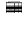
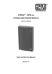
The ATEUS ® - COMFORT - Door Communicator 2000 User and Service Manual Version 3.3 Dear customer, We congratulate you on purchasing the product ® ATEUS - COMFORT - Door Communicator 2000, which represents new version of the well-proved product ® ATEUS - COMFORT - Door Communicator. This new high-tech product to development and production of which we have devoted exceptional care has an identical design, however, it also brings a number of new functions. It is our wish that you are fully contented with the door communicator on a long-term basis. Important note This version of the manual applies to a new issue, which is produced since September 2002. PCB (printed circuit board) has a label 2002 V3 (optionally V4, V5...). Differences are described bellow. The history of the product Version Description of changes 1 • First version of the product and the manual, 2000 2 • A new appendix to the manual - detailed instructions for outdoor installation. • Product is without changes, a bulb is enclosed to heat the interior and avoid water condensation. • Technological innovation - SMT *) • Direct heating on the PCB instead of the bulb • Chapter Installation in this manual is changed in accordance with these changes. • Wider range of busy tone detection. • Potentiometer for handsfree adjustment • Ground terminal for ESD protection (protection against electrostatic discharge). 3 *) Only the basic module was changed. Other modules and accessories remains the same, compatible with both old and new basic module. All ordering numbers are also unchanged. 2 CONTENT 1. FUNDAMENTAL PROPERTIES......................... 5 2. THE DESIGNATION ........................................ 6 3. ASSORTMENT OVERVIEW ............................. 7 3.1. 3.2. 3.3. 3.4. INDIVIDUAL MODULES ................................................................................. 7 BASIC COMPLETED SUITES ..........................................................................8 ACCESSORIES OF THE SYSTEM ..................................................................10 ACCESSORIES .........................................................................................12 4. TERMINOLOGY OVERVIEW .......................... 13 5. USER GUIDE ............................................... 14 5.1. 5.2. 5.3. 5.4. 6. 6.1. 6.2. 6.3. 6.4. 6.5. 6.6. 6.7. 6.8. 6.9. FROM THE VIEWPOINT OF AN EXTERNAL USER (GUEST).................................14 WAYS OF CALL TERMINATION - THE SUMMARY .............................................15 FROM THE VIEWPOINT OF AN INTERNAL USER - FUNCTIONS OVERVIEW ...........15 REVIEW OF THE DOOR COMMUNICATOR SIGNALLING ...........................16 USER MANUAL - THE KEYPAD MODULE ....... 18 THE CODE LOCK.......................................................................................18 THE CLASSIC BUTTON TELEPHONE .............................................................19 TRANSMISSION OF TONE DIALLING DURING AN OUTGOING CALL ......................19 SUBSTITUTION OF BUTTONS ......................................................................20 ALLOWABLE COMBINATIONS OF THE KEYPAD FUNCTIONS ..............................20 USER MANUAL FOR KEYPAD OPERATION - THE SUMMARY ..............................20 MOST COMMON QUESTIONS CONCERNING FUNCTION OF THE KEYPAD .............22 TIPS FOR SELECTION OF PASSWORDS.........................................................23 DOOR COMMUNICATOR MODES AND REALISABLE ACTIONS ................................24 3 7. SERVICE INSTRUCTION ............................... 25 7.1. MECHANICAL MOUNTING...........................................................................25 7.2. BUTTON LABELS - EXCHANGING OF THE LABELS ...........................................38 7.3. THE ELECTRICAL INSTALLATION .................................................................40 8. 8.1. 8.2. 8.3. 8.4. 8.5. 8.6. 8.7. 8.8. 8.9. 9. PROGRAMMING OF THE DOOR COMMUNICATOR ......................................... 51 BEFORE YOU START .................................................................................51 ENTERING INTO THE PROGRAMMING MODE ..................................................51 THE PROGRAMMING .................................................................................52 AN ERROR DURING PROGRAMMING.............................................................52 SWITCH NO. 1 PASSWORDS AND THEIR PROGRAMMING ................................53 PASSWORD LIMITATIONS ...........................................................................53 DELETING OF ALL PASSWORDS, ALL BUTTON MEMORIES, INITIALIZATION .........53 THE END OF PROGRAMMING ......................................................................54 NOTES:...................................................................................................54 MAINTENANCE ............................................ 56 9.1. CLEANING ...............................................................................................56 9.2. EXCHANGING OF LABELS, CHANGING THE PROGRAMMED SETTINGS ................56 10. TECHNICAL PARAMETERS AND REQUIREMENTS .......................................... 57 10.1. TELEPHONE PART ....................................................................................57 10.2. OTHER PARAMETERS................................................................................58 4 1. Fundamental Properties • tone dialling • programming via telephone • detection of hang up and busy line • uncompromising power supply from the line • superior acoustic properties • modularity - the maximum of 50 buttons + keypad • lighted buttons - LED • electrical lock switch - controlled directly from the telephone • optional second switch • can be used as common telephone (with the keypad only) • simple installation • possibility of numerical keypad: - instead of buttons - replaces up to 72 buttons has the function of a code lock robust metallic realisation can be used to dial a number 5 2. The Designation ® ATEUS - COMFORT - Door Communicator 2000 can replace classic bell button table with a loud telephone and a whole system of distributions, bells, and residential door telephones in objects where the branch telephone exchange is installed. Its installation is very simple; it is simply connected to one local line of the branch telephone exchange. Its use is simple as well - you just press some button and the door communicator "calls" the number previously stored in the ® appropriate memory. The number of buttons is selectable for ATEUS COMFORT - Door Communicator 2000 is a building-block system. ® ATEUS - COMFORT - Door Communicator 2000 has a built-in switch to control an electric door lock by any phone (entering a password in DTMF) In addition to the buttons, the numerical keypad can be used as well, serving as a code lock. Using the keypad, the system can also be used as a button telephone, and the dialled number can be either entered directly or selected from all of the 72 memories. The keypad and buttons can be combined and undesirable functions can be disabled. ® - COMFORT - Door Communicator 2000 provides more ATEUS sophisticated and broader services than common residential telephones. This is due to the fact that it can make use of services of a branch telephone exchange, e.g., redirection in the case of absence (to another workplace, to the answering machine, etc.) or call switching (e.g. from the secretariat to the concrete desired person). ® With its parameters, ATEUS - COMFORT - Door Communicator 2000 meets all requirements for systems designed for connection to a PSTN (telecommunication network in most European countries), and is certified as homologous for connection to a PSTN in the Czech Republic. 6 3. Assortment Overview 3.1. Individual modules 1 4 1. 2. 3. 4. 5. 6. 2 5 3 6 basic module with one button ord.no. 9132011 basic module with two buttons (1x double-button) ord.no. 9132021 module with four buttons ord.no. 913204 module with eight buttons (4x double-button) ord.no. 913208 module with eight buttons (2 modules 4-button + interconnection) ord.no. 9132081 numerical keypad module ord.no. 9132191 code lock module ord.no. 913220 Note: the independent code lock has an independent manual 7 3.2. Basic completed suites 1 3 2 5 4 6 8 9 8 7 1. 2. 3. 4. 5. 6. 7. 8. with 1 button with 2 buttons (1x double-button) with 5 buttons with 10 buttons (5x double-button) extension module 8 eight buttons extension module with 16 buttons (8x double-button) with one button and keypad with two buttons (1x double-button) and keypad ord.no. 9131011 ord.no. 9131021 ord.no. 9131051 ord.no. 9131101 ord.no. 913117 ord.no. 913118 ord.no. 9131151 ord.no. 9131161 9. code lock (independent) ord.no. 913120 Note: the independent code lock has an independent manual 9 3.3. Accessories of the system 10 Front frames for setting in masonry Front frame with box SL/C451-1 for 1 panel Front frame with box SL/C451-2 for 2 panels 1. Front frame with box SL/C451-3 for 3 panels ord.no. 91505011S ord.no. 91505012S ord.no. 91505013S ® Frames with the installation box serve for installation of ATEUS - COMFORT DOOR COMMUNICATOR 2000 modules (building of suites according to the specific wish), and for installation of other modules (e.g., the system of residential telephones, videophones, web-cameras etc.). Cover frames 2. Cover frame SL/C461-x - for x panels ord.no. 9150504xS (to improve aesthetic impression - overlap on all sides by 7 mm) 3. Cover frame SL/C 471-x - for x panels (small roof) ord.no. 9150505xS (for protection against rain in the outside setting) Note: Cover frames can be used for 1, 2, 3, 4, 6, and 9 panels. 4. Front frames for surface fitting Front frame with box SL/C481-x - for x panels ord.no. 9150503xS Front frames for surface fitting can be used for 1, 2, 3, 4, 6, and 9 panels. They represent an alternative to standard frames (for setting in masonry). For protection against rain in the outside setting, they are equipped with a small roof providing rain protection). 11 3.4. Accessories 1. 2. 3. 4. 5. tamper (safety contact) for alarm system DC / AC 50 V / 2 A switch module tool for safety screws safety screw, 2 pcs safety screws – set of 20 pcs ord.no. 9132092 ord.no. 9132093 ord.no. 9132097 ord.no. 9132098 ord.no. 9132099 3 4 2 12 4. Terminology Overview Picking up the line - a begin of the call, analogy to lifting of the handset Hanging up the line - the end of the call, analogy to laying down the handset DTMF - shortcut used for tone dialling Outgoing call - connection done in direction from the Door Communicator Incoming call - connection done in direction from phone to the Door Communicator Programming mode (or mode) - state, in which the Door Communicator can be programmed (can be reached from incoming call only) Code lock - mode, in which a password is entered from the keypad in intention to activate switch No. 1 or 2. Telephone mode (or mode) - keypad is used to pick up the line, then for dial a number and for hook up finally. Transmission of DTMF during an outgoing call - can be applied only to the outgoing call - if enabled, every button at the keypad causes transmitting of its DTMF signal Substitution of buttons - using of the keypad in place of large number of buttons to dial pre-programmed numbers only. 13 5. User Guide 5.1. From the viewpoint of an external user (guest) Buttons on the door communicator are provided with labels just like regular bell buttons. The visitor looks for the proper button (e.g., "Mr. Smith") and presses it. In this way the door communicator is activated. It lifts the line, and from the loudspeaker the telephone exchange dialling tone can be heard. After the preset time the door communicator "dials" the number (using pulse or tone dialling depending on what dialling type is set). Then the ringing tone can be heard from the loudspeaker. At the same time, the relevant telephone is ringing (in this case it is the telephone of Mr. Smith). In the case of branch telephone exchanges of 2N Co. Ltd., it is moreover possible to differentiate calling from the door communicator by different ringing type (thus before Mr. Smith pick up the telephone, he knows that this is a visitor calling from the front door). When the called person pick up the line, both of them can talk. The guest can speak into a built-in, sensitive microphone, even from a greater distance (depending on the surrounding noise). If an electric lock is connected to the door communicator, the called person can open the door for the guest. When the called person hangs up, the door communicator hangs up as well as for it evaluates the telephone exchange tone. The door communicator hangs up as well when it hears the "busy line" tone. If the call lasts longer than the preset time, the door communicator hangs up as well, and 10 seconds before doing so it issues a warning tone, and the called person can extend the call to 30 seconds (repeatedly as well). Notes: • • If the guest presses the same button again during the call, the door communicator hangs up. If the guest presses another button, the door communicator hangs up for 1 second and then it "dials" the new number. If the guest presses a button for which no number has been programmed, the door communicator picks up the line, sends the "refusal" signal (see the signalling overview), and shortly afterwards it hangs up again. 14 5.2. Ways of call termination - the summary 1. busy line tone or permanent tone after the call termination, 2. 3. 4. 5. the person "on the other end" pressed the character , expiration of the preset maximum call length, pressing of the button on the door communicator during the call, wrong service password 5.3. From the viewpoint of an internal user - Functions overview • • Calling to the door communicator You can just call the appropriate branch telephone exchange and the door communicator picks up the line after the first ring and issues the confirmation tone. In this mode, it is possible to control both switches, program the door communicator (see further), thanks to high sensitivity of the microphone it is possible to listen what is happening "outside", and also to speak (e.g., to warn people in the street to keep away, etc.). Opening of the door The door communicator is equipped with in itself a switch to which an electric lock can be connected (is not a part of the door communicator). This switch can be controlled via telephone after entering the password. The closing time of the lock can be set. This function also ends the call after the subsequent 30 seconds. Note: During entering of the password, every next character in the row must be entered not later than within five seconds, otherwise the door communicator sends the “refusal” signal, the same as in case of the wrong password (this time can be set otherwise). 15 • • Control of the second switch (e.g., illumination): In the same way, it is possible to control the second switch as well (if an additional module is installed). Signalling of the switch closing (both switches) After entering the password, the person at the telephone hears a confirmation signal, then the switch closes. During the time the switch is closed, it is possible to keep on speaking (e.g., to say "the door is open", or to listen (opening sound of the door, ...). After the closing time of the switch elapses, the person at the telephone hears the "saving" signal (see the signalling overview). • Talk extension 10 seconds before the end of the talk, the door communicator beeps, and on the telephone (when tone dialling is set), this time is by pressing extended by 30 seconds. This function can be used repeatedly. The guest cannot use such a function! • Programming Entering this mode is protected by a password. For detailed description see the service manual, the chapter Programming. Note: Functions activated by pressing with the possibility of tone dialling. or ) require use of a telephone 5.4. Review of the DOOR COMMUNICATOR signalling The DOOR COMMUNICATOR uses several various signals for the communication with the service during the programming, talk, etc. The review of these signals and their meaning is stated in the following table: 16 signal name meaning • ♪♪ confirmation • • • • ♪ ♪ ♪ ♪♪ ♪ refusing (error) • • ♪♪ ♪ ♪ ♪♪♪ a long permanent tone • storing hanging up deleting • during an incoming call it sends to the line immediately after picking up (the calling party hears) during the programming that confirms the entered service password or the number of the function was accepted and is correct during an outgoing and incoming call it signals that in 10 seconds runs out the defined maximum length of the call after entering of the service password it signals that the password is wrong or the programming is forbidden (by a write-protect jumper) during the programming it signals that there was an invalid number entered after connecting DOOR COMMUNICATOR to the line, it can be heard from the loudspeaker – the connection signalling after the incoming call is sent out in, if DOOR COMMUNICATOR is not programmed or the data in the memory is damaged during the programming it signals that the entered value is correct and was saved after activation of the switch by a DTMF, it signals the end of activation it is sent immediately before finishing of the call (in all cases) it is sent during the memory erasing by functions 97, • 98 and 99 loudspeaker beeps during activation of switch by a • keypad 17 6. User Manual - The Keypad Module ® Every basic module of the ATEUS - COMFORT - Door Communicator 2000 is made ready for connection of a keypad. By connecting this keypad (or by purchasing a system equipped with the keypad), it is possible to acquire a number of functions: classic code lock • classic button telephone • transmission of tone dialling during an outgoing call • substitution of buttons • Characteristic features of the keypad module are the robust metallic realisation and a very advantageous ratio of the price and use value. Individual functions are described below from the user point. 6.1. The code lock It is often advantageous to control the connected electrical lock not only via the telephone but also directly "from the door" - by the keypad. In this mode, the keypad behaves as a fully classic code lock and has the following possibilities: password length up to 10 digits • number of passwords up to 10 for switch 1 • closing time of switch 1 up to 9 seconds • possibility to control the second switch as well (using one password) • acoustic signalling of the switch closing - permanent tone • The code lock uses the same passwords which are also used for controlling of switch 1 via telephone. Only the initial passwords (00 for switch 1 and 11 for switch 2) cannot be used "from the keypad" as they are commonly known. 18 The control Enter the correct password and the character . If the password is valid, a long tone is heard which lasts for the preset time (usually 5 s). During this time, switch 1 or switch 2 is closed, (switch 1 usually controls the electric lock). If the password is invalid, the door communicator sends the "refusal" signal. 6.2. The classic button telephone In this mode, it is possible to "dial" an arbitrary number. The key serves is used to hang up. Authorisation for "outgoing" calls for pick up and the key must be cancelled if needed at the branch telephone exchange. The dialling type (tone, pulse) is set in the programming mode. If pulse dialling is set, the character functions (after picking up) as transition to tone dialling - similarly as on any other telephone. 6.3. Transmission of tone dialling during an outgoing call This function allows to send the tone dialling after establishing connection with one of the programmed numbers. It is used in combination with automatic information systems, voice boxes etc., which require from the calling person selection of a service using tone dialling. This function thus does not allow to reach other than programmed numbers. 19 6.4. Substitution of buttons This function is an analogy of comfort telephones memories. After pressing two digits in the range of 01 to 72 (the zero cannot be left out!), call to the programmed number is realised. From this point forward, function of the door communicator is fully identical as after pressing a button - the door communicator can thus be used as if it had up to 72 individual buttons, and in this way it is possible to "save" the buttons. It is ideal to use several classic buttons for the most important preselections (e.g., the director, the secretary, ...). If other preselections are intended for guests too, a list of them should be placed close to the door communicator. 6.5. Allowable combinations of the keypad functions All 4 functions given above can be combined arbitrarily - every one of them can be enabled or disabled independently according to the particular need. 6.6. User manual for keypad operation - the summary • Door opening - the code lock insert any valid password for the 1st switch and the character Attention! password 00 cannot be used! • Closing of switch 2: insert a valid password for the 2nd switch and the character Attention! password 11 cannot be used! 20 • Classic button telephone in the “off hook” state - the line is picked up … after picking up - a number is dialled when pulse dialling is set - switches to tone dialling when tone dialling is set - a character is transmitted anytime during the call - the line is hung up • sending of tone dialling during an outgoing call (after pressing an individual button, not in the telephone mode!) … !- dials the number, always in tone dialling , - both characters are normally transmitted substitution of buttons: 01…72 - after the preset time, the number corresponding with the relevant button (memory) is dialled - by pressing the asterisk after entering the number 01...72, the number is dialled immediately, however, the number must not be identical to a password. on the keypad can also be used to terminate an outgoing call if Note: button the tone dialling transmission is not used during the outgoing call. 21 6.7. Most common questions concerning function of the keypad • • • • Can a switch be closed permanently? No, the maximum closing time is 9 seconds. If some appliance needs to be switched permanently, a suitable auxiliary relay must be connected and controlled by two switches - one for closing and one for opening of the relay. Is it possible to realise such a setting in which after a single command, one switch closes first and after a while the other one closes too? No, every switch needs to be switched using its password. A suitable time relay could be connected to realise this function. However, it is possible to close both switches gradually. Can both switches be closed at the same time? Yes, via the telephone, during the time in which one switch is closed, the other one can be closed by using another password. This extends the closing time of the previously closed switch for it will be opened together with the one which had been closed later. When using control via the keypad, this is not possible. Can I use the code lock in the time when another person is speaking through the door communicator? Preferably not, this is a question of the password confidentiality and of respectable behaviour towards the person. It is technically possible in the case of an outgoing call if the function "Sending of tone dialling into the call" is not enabled. Attention is to be paid to other modes - it could happen that the door communicator is in the "telephone" state or that an incoming call is active. A code lock which is entirely independent of the door communicator but has the identical design, can be purchased independently (see the Assortment Overview). 22 • • What happens if the buttons substitution function is enabled and I press a number which has no programmed memory? The same thing happens as in the case of pressing an independent button which has not been programmed: the door communicator picks up the line, beeps the "refusal" signal (see the Signalling Overview), and hangs up immediately. What happens if the code lock is enabled as well as the buttons substitution function and some password is identical to the number of the memory? The code lock function has the highest priority. If for example, the password is 33 and you press , the switch is closed without the asterisk, after the preset delay immediately. If you press the line is picked up and number stored in memory 33 is dialled. 6.8. Tips for selection of passwords Tip 1: Letters on the keypad can be used for easy memorising of the password. If for example, we choose the password "Sebastian", it is the same as 732278426, but much easier to remember instead of the nine-digit number. Tip 2: It is not advisable to use passwords such as "3333". As this would be obvious to somebody watching. It is ideal to use all keys equally, preferably by using several codes for various persons or groups. 23 6.9. Table 1: Door Communicator modes and realisable outgoing call incoming call programming telephone mode keypad Action holding of a button - a new call talk extension - DTMF * end of call - DTMF # hook-up done by permanent or busy tone activation of the switch by DTMF password entering a programming mode activation of the switch - code lock DTMF dialling during an outgoing call "button substitution" pick up by * key (into telephone mode) hang up by # key on-hook actions ! ----------" --" " --- ! ! ! ! " --"1) " "1) --!1) --! ! ! " ! ----------- ----! ----------------- ! ! ! ! " ----!2) ----! Annotations: !… Yes, always " … Yes, in the case if this function is enabled 1) Yes, if dialling during an outgoing call is not enabled 2) If pulse dialling is selected, it is possible to switch into DTMF by pressing but not vice versa. 24 key, 7. Service Instruction 7.1. Mechanical Mounting Mounting Methods Overview Mounting Environment Installation Requirements Non-mandatory: Protecting frame • • • • • indoor • order No. 91505041S (for 1 module) order No. 91505042S (for 2 modules) order No. 91505043S (for 3 modules) order No. 91505044S (for 4 modules) order No. 91505046S (for 6 modules) order No. 91505049S (for 9 modules) Cement wall Protecting roof • • • • • order No. 91505051S (for 1 module) order No. 91505052S (for 2 modules) order No. 91505053S (for 3 modules) order No. 91505054S (for 4 modules) order No. 91505056S (for 6 modules) order No. 91505059S (for 9 modules) • Waterproof cement *) outdoor wall Front frame with surface mounting box • • • • • indoor and order No. 91505031S (for 1 module) order No. 91505032S (for 2 modules) order No. 91505033S (for 3 modules) order No. 91505034S (for 4 modules) order No. 91505036S (for 6 modules) order No. 91505039S (for 9 modules) • surface outdoor Waterproof cement *) *) Safety bolts (order No. 9132098 or 9132099 ) are recommended for indoor use (see the Product Mix Overview). 25 7.1.1. Explanatory Notes to Table Indoor environment means for the purpose hereof: • Indoor space with a low relative humidity (such as corridors, offices and other environmentally controlled rooms); • Indoor space where moisture condenses on walls but does not run down the wall in any case (such as verandas, warehouses, industrial facilities); • Outdoor space with guaranteed weather (rain, water running down the wall) protection (such as shelters, passages). Outdoor environment means for the purpose hereof: Environment where the product is exposed to rain or where water may run down the wall (such as fences, outer building walls). WARNING! The warranty does not relate to product failures and defects arising as a result of wrong installation (in contradiction herewith). Furthermore, the manufacturer assumes no liability for losses incurred through theft from spaces that are accessible after opening of the electric lock attached. The product is not intended as protection against thieves – to protect an object, it has to be combined with a conventional safety lock. 26 7.1.2. Drawings of Wall Mounting Holes The Porter is usually wall-mounted, i.e. installed into a hole as shown in Fig. 1 or Fig. 2.: 120 50.0 40.0 120.0 34.0 °17 30 možné otvory v boku Fig. 1: Small Box Wall Mounting Hole (1 Module) 27 120 140.0 130.0 210.0 34.0 °17 30 možné otvory v boku Fig. 2: Big Box Wall Mounting Hole (2 Modules) Mounting multi-box sets, bring boxes together with necks and measure the set properly before installation. 28 7.1.3. Wall Mounting Procedure 1. 2. 3. First remove the installation box from the set to be mounted as follows: Remove the bolt covers on the plastic front panel frame. Unscrew the two bolts fully and open the Porter. Pulling slightly, unhinge the front panel including hinges from the box holes. (To replace the box after mounting, follow the reverse order of the procedure). Before mounting, break the conductor hole in the box to be used. With multi-box sets, break interconnection holes too and bound boxes together using plastic necks. Be sure to brick in the box properly according to Fig. 4 ensuring that it does not jut out of the wall. If, on the contrary, it is slightly below the wall surface, the Porter front panel fits closely to the wall and the offset does not matter. If it juts out of the wall, the front panel fits to the box, not flushing with the wall (see Fig.4). CAUTION! Remember to keep all hinge and bolt holes clean while mounting! You can cover them with a sticker available for this purpose on the box bottom. If the holes get dirty, we recommend you to remove the mortar (plaster, etc.) as soon as possible before it hardens. CAUTION! The small box is of an almost square shape and so keep in mind that the bolt holes should be on its upper and bottom sides! Fig. 3: Correct and Wrong Box Orientations 29 Sealing Wall Front Panel Mortar Installation box Correct Wrong Fig. 4: Correct Wall Mounting 30 Indoor Wall Mounting Indoors, the rest of the set can be mounted in the installation box directly. If the wall surface around the Porter is rough or damaged, you can use a protecting frame available separately (see the Product Mix Overview). Gaps, if any, between the frame and the wall can be filled with some suitable jointing compound. In high relative humidity environments, it is advisable to connect (using the electric lock power supply, e.g.) a backlight to heat the installation box interior and avoid water condensation. For installation options see Fig. 5. CAUTION! The above-mentioned installation, however, cannot prevent running-down water from penetrating in the box interior in any case (see Fig. 8). 31 Without Frame Plaster Protecting Frame With Frame Fig. 5: Indoor Wall Mounting Detail 32 Outdoor Wall Mounting (Where the Porter is exposed to rain or where water may run down the wall) Principles to be obeyed: • Always use a protecting roof to protect the equipment against rain. • Fill the space between the roof and the wall with some jointing compound to avoid leaking of water into the box (Fig. 7). The gasket break must always be on the bottom panel side (Fig. 6). Water must not leak along or around cables. The backlight must be powered to heat and dry up the box space and prevent water condensation. • • • • With more modules, always put the basic module on the top to protect it against rain as well as possible - Fig. 9. Jointing compound Protecting Roof Front Panel Fig. 7: Correct outdoor Mounting 33 Place gasket break down Fig. 6: Correct Location of Sealing Fig. 8 shows the correct and wrong outdoor wall mounting techniques. Correct – water drains from the roof edge Wrong – the protecting frame does not prevent water leaking through the front panel Wrong – jointing compound is missing – water can leak between the frame and wall Wrong – gasket on the wall does not eliminate water leaking Fig. 8: Correct and Wrong Ways of Outdoor Wall Mounting 34 Surface Mounting For surface mounting use the front frame with the surface-mounting box (see the Product Mix Overview). To disassemble it, follow the instructions below: 1. Remove the bolt hoods on the front panel plastic frame. 2. Unscrew the two bolts fully and open the Porter. 3. Pulling slightly, unhinge the front panel. 4. Unscrew the four bolts on the plastic installation box bottom and remove the box from the metal protecting roof. (To replace the box after mounting, follow the reverse order of the procedure). Break cable holes in the protecting roof and installation box, and drill required wall mounting holes. The following steps are different for each mounting environment. 7.1.4. Indoor Surface Mounting You can fit the protecting roof to the wall directly using, e.g., dowels and screws. Then, you can mount the rest of the set into the installation box directly. In high-relative-humidity environments, connect a backlight to a power supply to heat the installation box interior and avoid water condensation. CAUTION! The above-mentioned installation, however, cannot prevent running-down water from penetrating in the box interior in any case (see Fig. 9). 35 7.1.5. Outdoor Surface Mounting In outdoor environments where water runs down the wall, it is always necessary to pack perfectly space between the protecting roof and the wall using jointing compound to avoid water leaking into the installation box (see Figs. 10 and 11). Having inserted and fitted the plastic installation box including a protecting frame, fill the space between the protecting frame and the roof with jointing compound too to avoid leaking of water drops running on the bottom roof side (see Figs. 10 and 11). Furthermore, pay attention to the position of the rubber gasket in the Porter front panel. The break has to be on the bottom pane side (see Fig. 5). The backlight must be connected to a power supply to heat and dry up the installation box interior and prevent water condensation. While installing more modules, always protect it against rain as well as possible. put the basic module on the top to Correct – the basic module must always be up Fig. 9: Correct Module Arrangement 36 Wrong For a correct outdoor surface mounting technique see Fig. 10. Protecting Roof` Jointing compound Jointing compound Protecting Frame Fig. 10: Correct Outdoor Surface Mounting Fig. 11: Wrong Outdoor Surface Mounting 37 Notes to Mechanical Mounting Reverse-Side Opening: The installation box is symmetrical, with hinges in the right or left. To reverse the opening direction, remove the modules from the frame and turn them by 180° to avoid their upside-down position. Safety bolts: Safety bolts are special bolts that can be unscrewed using a special wrench, thus making potential thefts more difficult. The bolts and tool are available separately; refer to the Product Mix Overview. 7.2. Button labels - exchanging of the labels 7.2.1. Material of the labels A special foil is provided for the button labels which is sufficiently and evenly transparent. It is necessary to remember that using of unsuitable material can have substantial effect on the illumination quality, and thus also on readability of the buttons description in the night. 7.2.2. Insertion - exchange of labels Thanks to construction of the buttons, this step requires no expert qualification and the door communicator need not be opened either. A special wrench is provided with every set or frame - a bent thin metal leaf (the plangette) using which it is possible to take the cover with the label out of the button. The cover is divided into two parts between which the label is inserted. 38 Fig. 13: Push tenderly the opposite end of the button and take out after its release. Fig. 12: Insert the plangette under the button and heave it tenderly. Fig. 14: using the plangette, separate both parts of the cover each other and insert the label inbetween them 39 7.3. The electrical installation 7.3.1. A telephone line requirements The Door Communicator can be connected, regardless of polarity, to any common “analogue” telephone line; i.e. line destined for ordinary telephone apparatus. Electrical parameters of this line can vary in a wide range – see technical specifications. Both pulse and DTMF dialling can be accepted. Of course, DTMF dialling is preferred, because it is faster. It is preferred by most of today’s PBX’s, too. Usually, the Door Communicator is connected to local PBX. For some special purposes, it can be connected to public telephone network line, too. A big advantage of the DOOR COMMUNICATOR is the fact that it does not need any other power supply for its basic operation. 7.3.2. Connecting to a telephone line The telephone line is connected to terminals „LINE“; see fig. 16. It is enough fir basic functioning of Door Communicator – without a backlight and an electric lock, of course. The Door Communicator sends a signal “error” by its speaker immediately after connecting to the line. (It will not happen, if the Door Communicator was disconnected for a short time only.) 7.3.3. Parallel connection Parallel connection of two or more telephone devices to one telephone line is a poor practice in some undeveloped countries. This practice produces some real hazards and discomfort. Especially the Door Communicator is not to be connected in parallel to any other telephone device. It must be always connected solitary to its own line. Furthermore, any device for line sharing cannot be inserted between a PBX and the Door Communicator. 40 connector for extension module terminals for telephone line terminals for backlight supply switch No.1 fuse, max. 2A terminals of switch No. 1 ground (ESD protection) connector for loudspeaker and microphone programming disabled connector for switch No. 2 module programming enabled Fig.15: PCB layout diagram with description of terminals 41 connector for keypad 7.3.4. Electric lock standard connection The Door Communicator is equipped with a universal switch, which is led to the terminal “Switch No. 1” (see fig. 15). It is a "normally open contact” – in the fact it is a solid-state (semiconductor) relay with "on" resistance approx. 0,5 Ω. The "contact" is electrically (by photocoupler) isolated from the telephone line, but it is designed exclusively for a low voltage usage: it cannot drive mains voltage of either 230 V or 120 V and it cannot be connected with circuits, which are powered directly from mains power supply. The permitted voltage is 9 to 48 V, DC or AC. The switch is protected against a higher voltage by an overvoltage protection (MOV). The driven current is max. 2A. The relay is protected against a higher current, too - by a tube fuse T (slow) 2,0 A in a holder. The switch can operate with both AC and DC, regardless to polarity. It is necessary to check switched voltage and current for their limits (see technical requirements). It is also a good practice to check (compare) electrical parameters of electric lock and its power supply. In ANY CASE it is NOT ALLOWED to switch mains voltage 230 or 120 V !!! The recommended and most custom supply voltage for electric locks is 12V. This voltage can be used for backlight supply, too. AC or DC power supply: both AC and DC can be used to drive almost electric locks. AC power supply is favourable, because the lock serves as a buzzer in this case and it is a clear signal “door is free”. Note: In the case of power failure, and PBX is still working, users has no information about it – the Door Communicator will send a confirmation signal during “opening“ but the lock cannot work, of course. 42 7.3.5. Backlight supply standard connection ® A great plus of ATEUS - Door Communicator 2000 is a high-quality illumination of buttons. It is based on a number of yellow LEDs (Light Emitting Diodes) under each button. This backlight has an advantage of low power consumption, long life and uniform intensity. If there is a recommended 12Vsupply used for electric lock, it can be used for backlight supply, too. In this case, backlight power supply is connected as on fig. 16. It is necessary to check up power supply unit ability to supply a required current permanently. Also a good cooling must be ensured – it is not recommended to cover the power supply unit with any thermal insulating materials, or to situate it on the place with poor ventilation. As opposed to a power supply for electric lock alone, in this case a load is permanent! A required current is depending on a number N of buttons (or double-buttons). It can be evaluated by a formula: I = 16 x N +50 [mA]. A part of this current us used to heat the interior and avoid water condensation. 7.3.6. Ground terminal connection - ESD protection A person, coming to the Door Communicator, may carry an electrostatic charge with voltage several thousands Volts. As soon as a space between finger (e.g.) and a panel of the Door Communicator decreases to several mm, a spark will jump between them. Ground terminal, if connected, will tap this charge to the ground. If ground conductor is not available, it is possible to connect this terminal to one of line terminals *). The charge is then tapped to ground through input protection circuit in PBX. Moreover, some PBXs have one line terminal connected with ground. *) Note: This connection will not bring line voltage to the panel, because there is M.O.V. (Metal Oxid Varistor) connected in series. 43 Ground (Recommended) tel. line 12 V supply, AC or DC Electric lock Fig.16: The Door Communicator standard connection 44 7.3.7. Two separate power supply units for the backlight and the electric lock tel. line AC or DC supply 48V max. Two separated power supply units are necessary in case if there is an electric lock for more than 12 V supply used. Then it is necessary to use another (12V) power supply unit for backlight. It is to be connected to terminals “Backlight”, see this fig.. This connection may be also useful to reduce power consumption from battery backedup power supply, if it is used for an electric lock. It can be used also if there is not available such power unit, which can drive both electric lock and backlight together. electric lock 12 V supply, AC or DC Fig. 17: Connection of two separate power supply units for the backlight and the electric lock 45 7.3.8. Connection of switch No. 2 (with an auxiliary module) auxiliary switch module AC or DC supply 48V max. The switch No. 2 can by connected via a JP4. It is a TTL output on JP4, which is designed to drive only a special auxiliary module. Attention! JP4 is electrically connected to the line! Only a special SSR module from the manufacturer, e.g. order No. 9132093 can be used. This module provides a necessary electrical isolation. The schematic diagram of its connection is in this fig. Fig.18: Connection of switch No. 2 46 load driven Security switch - tamper (optional, see assortment overview) So-called sabotage switch (tamper) is destined for connection to an alarm system. It can be connected into “sabotage” (24-hour) loop of the alarm system to cause an alarm if the Door communicator was opened. Montage of the security switch is very simple – it is to be pulled into a gap in a plastic part of a frame, in accordance with instructions enclosed to the switch. It has a “normally closed” contact, which can be connected in series with a number of another switches. 7.3.9. Keypad connection Connection of the keypad is very simple – a single cable, plugged into connector JP5. This connector and the cable are protected against a wrong connection by a key. If the keypad was delivered as a part of a complete product, it is already connected, of course. 7.3.10. Connection of expansion modules with buttons Building of big configurations ® A great advantage of ATEUS - Door Communicator 2000 is that it is very easy to build configurations with a large number of buttons (up to 50). It was never so easy: they are connected each one by a single cable to a chain. Every module is connected with a previous one with an enclosed cable; first extension module is connected to a main board. Every extension module has two connectors – input (to previous) and output (to next). For a regular order of buttons, they are not to be connected in reverse order! Extension modules are connected in the way that each next module has button numbers increased by 8 from the previous one. If there are modules with four single-buttons connected in this way, a row of button numbers will be discontinuous. So as all button numbers can be used for these modules, they are offered partly single, partly in a pair together with a special cable, which makes this pair electrically identical to the module with eight buttons (4 doublebuttons. A correct connection is illustrated by following pictures. 47 Fig. 19: A proper connecting method for 4 single-button modules, delivered in a pair with a special cable enclosed. Fig. 20: Extension module proper orientation – keys are both on a bottom side of connectors. NEXT input connector 022B Fig. 21: A proper connection of double-button modules output connector NEXT PREVIOUS 48 Button numbers in a different configuration 1 3 4 5 6 2 7 8 9 10 11 12 13 14 19 20 21 22 15 16 17 18 23 24 25 26 27 28 29 20 25 26 37 38 31 32 33 34 39 40 41 42 43 44 45 46 47 48 49 50 Fig. 22: Button numbers in the configuration with double-buttons without a keypad 1 2 1 2 3 4 5 6 7 8 9 * 0 # 3 4 5 6 7 8 9 10 19 20 21 22 23 24 25 26 35 36 37 38 39 40 41 42 11 12 13 14 15 16 17 18 27 28 29 20 31 32 33 34 43 44 45 46 47 48 49 50 Fig. 23: Button numbers in the configuration with double-buttons with a keypad 49 1 15 16 17 18 31 32 33 34 7 8 9 10 23 24 25 26 39 40 41 42 1 2 7 8 9 10 Fig. 24: Button numbers in the configuration with single-buttons in case if a special cable is not used – some numbers are skipped. 47 48 49 50 11 12 13 14 19 20 21 22 27 28 29 30 35 36 37 38 43 44 45 46 15 16 17 18 23 24 25 26 31 32 33 34 39 40 41 42 47 48 49 50 3 4 5 6 Fig. 25: Button numbers for the configuration with single-buttons – proper without a keypad 1 1 2 3 4 5 6 7 8 9 * 0 # 3 4 5 6 11 12 13 14 19 20 21 22 27 28 29 30 35 36 37 38 43 44 45 46 7 8 9 10 15 16 17 18 23 24 25 26 31 32 33 34 39 40 41 42 47 48 49 50 Fig. 26: Button numbers for the configuration with single-buttons – proper with a keypad 50 8. Programming of the Door Communicator All programmable parameters, including a parameters for a keypad functions, are remote programmable per line by any phone with DTMF dialling (also a GSM cellular phone can be used for it). At first a programming mode must be entered. Access to this mode is protected by a service password. Optionally a hardware jumper can be used to avoid this access. 8.1. Before you start • • • Make sure that the programming is not restricted (connection JP1) - see picture No.15 and if your telephone supports the tone dialling. Use the prepared form, which is a table of all functions, and fill in all the values, which you want to change. If the DOOR COMMUNICATOR is not completely new, make sure, that you know its actual service password and if you are not totally sure, how the DOOR COMMUNICATOR is programmed, always use a complete initiation (Attention! The service password is also initiated!). 8.2. Entering into the programming mode The programming mode can be entered only during an incoming call (calling from a phone to the CE). For access a password must be entered in this form: service password . Don't forget an asterisk before and behind the password! The DOOR COMMUNICATOR sends out a confirmation, if the entered password is correct and the programming is allowed (connection JP1 see fig. 15.). This password is pre-set to 12345. Of course, it can be changed as well as another parameters. In case you change and then forget the password, the data is not yet lost – it is necessary to contact the manufacturer, though. When 51 entering the password, you have a 5-second limit (or a set limit of 1 to 9 seconds) for each character; otherwise the DOOR COMMUNICATOR hangs up. 8.3. The programming Once entered into the programming mode, you can change any values in any order. The steps are simple – first, you enter the number of the function, then its value, separated by asterisk - . So generally the function has the following form: Function number value The number of the function has two digits (see the table), and after entering this number and an asterisk, the DOOR COMMUNICATOR sends a confirmation signal (see the signals table) or an error, in case the function of the entered number does not exist. After entering the value and the second asterisk, the DOOR COMMUNICATOR sends a signal of storing (see the signals table) or an error, if the value is out of the permitted range. 8.4. An error during programming • • • If you make an error during entering the number (whether it is a function number or a value) and you recognise it before you press a asterisk, the and enter it again. whole number can be cancelled by pressing If the DOOR COMMUNICATOR sends an error signal, the programming can continue – the function number must be entered again even in case, that only its value was wrong. If you programmed a different value than you wanted and the value was stored, you can enter it correctly again, of course. 52 8.5. Switch No. 1 passwords and their programming Up to 10 different passwords can be used at the same time for a switch No. 1. These passwords are stored as a list. It means, they have no order and they are not numbered. It is possible to add a new password to this lift by a function 81, if the list is not full. An existing password in the list can be deleted by a function 82, if this password is known. If there are some unknown (forgotten) passwords in this list, the only way to delete them is a function 97 - see a table of functions. There is only one password - 00 - in this list as a default. It has such exception, as it is not to be used from a keypad. Also this password can be deleted by function 82 or 97. 8.6. Password limitations All passwords (incl. service password) are checked during programming. It is not allowed to enter twice the same password, and sub-strings are permitted too (e.g. if you leave the service password 12345, you cannot use a password 123, 123456, etc. for the switch. If you enter an invalid password, the CE sends out the “refusal” signal. 8.7. Deleting of all passwords, all button memories, initialization There are three following functions available for an instance if you wish to start over again to program a button memories, passwords or an everything: 97 - erases a whole list of switch No. 1 passwords 98 - erases all button memories 99 - a complete initialisation (password 00, 11 and 12345 are restored) 53 8.8. The end of programming • After storing of all values, which you needed to change, finish programming . The DOOR COMMUNICATOR sends a signal of hanging by pressing up and then it hangs up. • • • is not used, the DOOR COMMUNICATOR hangs up If the character later, but it has no influence on storing the values (they are stored into the memory immediately after entering) If you are not totally sure about it, check that the DOOR COMMUNICATOR is working according to your concept after programming. Save the filled form on a safe place. 8.9. Notes: • • Programmed values are stored in a non-volatile serial memory (EEPROM). This Memory is placed in a socket, so that it can be changed e.g. if the module must be replaced. Another way to save a programming time is co copy a memory content in a special programmer, if there is a need to program a large number of Door communicators with a same values. A used memory is a special type for a low voltage. It is not recommended to replace it by another type. Such replacement can cause an unreliable operating of the Door Communicator. • 54 Table No. 2: Programming table – functions review Function name not used 00 01-50 button memories F. No. 51-72 additional memories 73-80 not used a new password for switch No. 1 enter - up 81 to 10 passwords removing of an existing 82 password password for switch 83 No. 2 (only one) Range --up to 16 digits --up to 10 digits valid passw. up to 10 digits Default --empty empty --- --11 supervisor password 86 87 88 89 90 91 92 code lock mode 0-1 1 = enabled button substitution 0-1 0 = disabled telephone mode 0-1 0 = disabled DTMF during call 0-1 0 = disabled type of dialling 0-1 0 = DTMF No. 1 0-9 5 [s] switch "on" time No. 2 0-9 5 [s] time limit for next key on 1-9 5 [s] keypad time from pick up to 01-99 8 = 0,8 s start of dialling max. time of call 01-99 12 = 120s removing of all passwords for switch No. 1 supervisor all button memory clear passw. complete initialisation 95 96 97 98 99 only digits 0-9 can be entered for button substitution mode only reserved for a future use 1 default password 00 cannot be used password: 00 from keypad (only from phone) 85 94 Comments 12345 individually erases valid switch No. 1 password if entered enter an empty password (83**) to disable switch No. 2 check a write-protect jumper, if a valid password is refused 0 = disabled 1 = enabled see user manual - keypad module for explanation 1 = pulse 40/60 dialling 0 = switch No. 1 disabled 0 = switch No. 2 disabled during entering of password etc x 0,1 [s], range 0,8 to 9,9 s. x10 [s], range 10s-990s password 00 is deleted too clears a memories 01 to 72 attention! also change a supervisor password to default! 9. Maintenance 9.1. Cleaning In frequent usage, the surface, especially the keypad, gets contaminated with dirt unavoidably. To remove such dirt, usually some soft rag moistened with pure water suffices. We recommend following principles during the cleaning: Do not use aggressive cleaning means (dishwashing sand, acid, etc.) • Practice the cleaning under dry weather conditions when water possibly • entering inside dries out quickly 9.2. Exchanging of labels, changing the programmed settings The procedure is given in previous chapters. The following must be saved carefully so that nothing inhibits you from realising the changes according to the procedure: this manual • the filled programming form (we recommend to make a copy of it) • not used transparent foils for the buttons • the wrench for safety screws if applicable • 56 10. Technical parameters and requirements 10.1. Telephone part Parameter Minimal required off-hook line current Minimal required on-hook line voltage DC voltage drop (off-hook) Lead current when hang-up Off-hook AC impedance Return loss Bandwidth Ringing impedance Ringing detector sensitivity Time reaction to ringing Pulse dialling DTMF dialling level Call-progress tone detector sensitivity Detection speed for a busy tone Detection speed for a permanent tone Overvoltage protection – between A, B *) Note: any ringing style and period is accepted.. 57 Value 15 mA 22 V <8V < 16 V < 100 μA 220 Ω + 820 Ω parall. 115 nF > 14 dB 300 ÷3500 Hz > 2 kΩ C = 1 μF 10 … 20 V 1 period 40 / 60 ms 6 & 8 dB ± 2 dB 0 to 20 dB c/a 2 s max. 2s 4500 A Conditions off-hook state on-hook state I = 25 mA I = 50 mA U = 60 V 20 … 60 mA 20 … 60 mA 20 … 60 mA 25 or 50 Hz 25 or 50 Hz *) 20 … 60 mA 20 … 60 mA 350 - 500 Hz 350 - 500 Hz 8 / 20 μs 10.2. Other parameters Switch 1 - minimal voltage 9V AC or DC Switch 1 - maximal voltage 48 V AC or DC Switch 1 - maximal current 2A AC or DC Backlight nominal voltage 12V AC or DC Backlight max. voltage 24V AC or DC Backlight current consumption Max. 1 A Operating temperature range Allowable environment AC or DC -20 až + 60 ºC Outdoor environment with an additional protection against a rain Use the product for purposes, for which it has been designed and produced, in accordance with this manual. The producer reserves a right for realisation of such modifications of the product against the presented documentation, which shall lead to improving of the product properties. ® The ATEUS - COMFORT - Door Communicator does not contain components harmful for the environment. If this product can no more serve for the original purposes one day and can no more be used by you or elsewhere, dispose of it in accordance with valid legal provisions. 58 POZNÁMKY: DR 775/02 v.3.3 59 60 61 2002, 2N TELEKOMUNIKACE a.s. - Prague DR 775/02 v.3.3 62