1
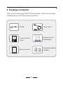
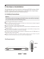
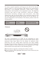
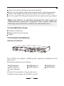
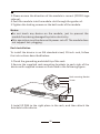
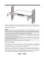
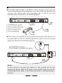
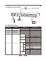
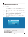
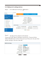
IP PHONE SYSTEM
CooVox Series-U100
For Small and Medium Business
Quick Installation Guide
PWR
SYS
WAN
LAN
4
3
2
SLOT2
1
4
3
2
SLOT1
1
CooVox
IP Phone System
www.zycoo.com
Table of Contents
1 Package Contents
03
2 Hardware Installation
04
2.1 Safety Precautions
04
2.2 Installation Tools
07
2.3 Product Installation
07
2.4 Physical Connection
11
2.5 LED Definitions
11
3 Basic System Configuration
12
3.1 Web Login
12
3.2 Network Configuration
13
3.3 Choose the Module
14
3.4 Reset to factory
15
4 Further Configuration
15
1 Package Contents
Thank you for purchasing ZYCOO IP Phone System. These are the items
included with your IP Phone System purchase:
Power Cord
IP PBX
Antenna(only for
GSM Module)
Quick Installation
Guide
Two mounting brackets
and fittings
Warranty Card
03
2 Hardware Installation
The followings are instructions for setting up ZYCOO CooVox-U100
IP PBX. Please refer to the illustration and follow the simple steps
below to quickly install your IP phone system.
2.1 Safety Precautions
Notes:
To avoid any device damage and bodily injury caused by improper
use, please observe the following rules.
Keep the power off during the installation.
Wear an ESD-preventive wrist strap, and make sure that the wrist strap has a good
skin contact and is well grounded.
Use only the power cord provided with IP PBX .
Make sure that the supply voltage matches the specifications indicated on the rear
panel of IP PBX.
Confirm not to bring about the overload of power circuit before turning on the
power of IP PBX, to avoid the unnecessary damage.
To avoid the electric accident, do not open or remove the cover of IP PBX when it is
working as well as off the power.
Before cleaning the device, cut off the power supply. Do not clean it by the
waterish cloth, and never use any other liquid cleaning method.
Site Requirements
40 C
0C
PWR
SYS
WAN
LAN
4
3
2
SLOT2
1
4
3
2
SLOT1
1
CooVox
IP Phone System
04
To ensure normal operation and long service life of the device,
please install it in an environment that meets the requirements
described in the following subsection. Please keep a proper
temperature and humidity in the equipment room. Too high/low
humidity may lead to bad insulation, electricity leakage,
m e c h a n i c a l p ro p e r t y c h a n g e s a n d c o r ro s i o n s . To o h i g h
temperature may accelerate aging of the insulation materials and
can thus significantly shorten the service life of the device. For
normal temperature and humidity of the device, please check the
following table.
Environment
Operating
Storage
Temperature
0 C~40 C
-20 C~55 C
Humidity
10%~90% Non-condensing
5%~95% Non-condensing
Clearness
PWR
SYS
WAN
LAN
4
3
2
SLOT2
1
4
3
2
SLOT1
1
CooVox
IP Phone System
The dust accumulated on IP PBX can be absorbed by static
electricity and result in poor contact of metal contact points. Some
measures have been taken for the device to prevent static
electricity, but too strong static electricity can cause deadly
damage to the electronic elements on the internal circuit board. To
avoid the effect of static electricity on the operation of IP PBX,
please attach much importance to the following items:
Dust the device regularly, and keep the indoor air clean.
Keep the device well grounded and ensure static electricity has
been transferred.
05
Electromagnetic Interference
PWR
SYS
WAN
LAN
4
3
2
SLOT2
1
4
3
2
SLOT1
1
CooVox
IP Phone System
Electronic elements including capacitance and inductance on the
device can be affected by external interferences, such as conducted
emission by capacitance coupling, inductance coupling, and
impedance coupling. To decrease the interferences, please make
sure to take the following measures:
Use the power supply that can effectively filter interference from
the power grid.
Keep the devices far from high-frequency, strong-current devices,
such as radio transmitting station.
Use electromagnetic shielding when necessary.
Lightening Protection
PWR
SYS
WAN
LAN
4
3
2
SLOT2
1
4
3
2
SLOT1
1
CooVox
IP Phone System
Extremely high voltage currents can be produced instantly when
lightning occurs and the air in the electric discharge path can be
instantly heated up to 20,000℃ . As this instant current is strong
enough to damage electronic devices, more effective lightning
protection measures should be taken:
06
Ensure the rack and devices are well earthed.
Make sure the power socket has a good contact with the ground.
Keep a reasonable cabling system and avoid induced lightning.
Use the signal SPD (Surge Protective Device) when wiring outdoor.
Note: the device is specially designed for the usage of
communication operators’ computer room; please obey the
following requirements for installation and maintenance.
2.2 Installation Tools
Phillips screwdriver
ESD-preventive wrist wrap
Cables
+
+
2.3 Product Installation
Module Installation
ANT
PWR
VGA
WAN
+
LAN
USB
AUDIO
+
4
3
2
1
+
+
4
3
2
1
This IP PBX can support installing two extension modules at the
same time.
Optional modules are as follows.
4FXS Module
4FXO Module
2FXOS Module
2GSM Module
4GSM Module
1.Check if the module is clean and intact.
2.Please ensure power of IP PBX is cut off.
07
1PRI Module
4BRI Module
3.Please ensure the direction of the module is correct (ZYCOO-logo
side up).
4.Push the module into the module slot through the guide rail.
5.Tighten the locking screws on the both ends of the module.
Notes:
Do not touch any device on the module, just to prevent the
module from being damaged by static electricity.
This operation must be done with power cut off. The module does
not support hot- plugging.
Rack Installation
To install the device in an EIA standard-sized, 19-inch rack, follow
the instructions described below:
1.Check the grounding and stability of the rack.
2.Secure the supplied rack-mounting brackets to each side of the
device with supplied screws as illustrated in the following figure.
Rack-mounting Bracket
Screw
PWR
SYS
WAN
LAN
4
3
2
SLOT 2
1
4
3
SLOT21
1
Coo
IP Pho Vox
ne Sys
tem
3.Install IP PBX to the right place in the rack, and then attach the
brackets to the device.
08
PWR
SYS
WAN
LAN
4
3
2
SLOT 2
1
4
3
SLOT21
1
Coo
IP Pho Vox
ne Sys
tem
4.After the brackets are attached to the device, use suitable screws
(not provided) to secure the brackets to the rack, as illustrated in
the following figure.
Notes:
Please ensure the correct installation for the grounding of the rack,
which is the most important guarantee of avoiding ESD, electricity
leakage, lightening, and electromagnetic interference;
Please mount devices in sequence from the bottom to top of the
rack to avoid overloading;
Please avoid any heavy thing placed on the device to avoid any
unexpected accidents;
Please ensure heat dissipation and air circulation.
Connect to Ground
Connecting the device to ground is to quickly release the lightning
over-voltage and over-current of the device, which is also a necessary
measure to protect the body from electric shock.
In different environments, the device may be grounded differently.
Two measures are given in the following, of which the Grounding bar
is better for the protection of lightening. Users can try to choose the
most appropriate measure according to different situation.
09
If CooVox-U100 IP PBX is installed in the computer room, and the
room has dedicated Grounding bar, then the using of ground wire to
connect the device with the Grounding bar is put to the first
consideration as shown in the following figure.
ANT
4
3
2
4
PWR
VGA
WAN
LAN
USB
1
2
3
4
1
2
3
SLOT2
AUDIO
1
SLOT1
[2]
[1]
[1] IP PBX(Rear panel)
[2] Grounding Terminal
[3] Grounding Cable
[4] Grounding Bar
[3]
[4]
If the device is installed in the normal environment, the device can
be grounded via the PE (Protecting Earth) cable of the AC power
supply as shown in the following figure.
L
N
[1] IP PBX(Rear panel)
[2] AC Power Cord(with PE cable)
ANT
4
3
2
4
PWR
VGA
WAN
LAN
USB
AUDIO
1
3
2
1
SLOT2
4
3
2
1
SLOT1
[1]
[2]
Notes:
If you intend to connect the device to the ground via the PE
(Protecting Earth) cable of AC power cord, please make sure the PE
(Protecting Earth) cable in the electrical outlet is well grounded in
advance.
10
2.4 Physical Connection
CooVox-U100
+
+
Computer
+
PWR
VGA
Power
WAN
LAN
USB
4
AUDIO
3
+
2
1
ANT
+
4
3
+
2
1
Router
PSTN
2.5 LED Definitions
Indication
Function
PWR
Power Status
SYS
System Status
ETH
Data Status
Status
On
Off
Blink
Off
Blink
Off
FXS
FXO
GSM
1-4(SLOT1/2)
L1
SLOT1/2 Status
L2
E1/T1
L3
L4
BRI
11
Green
Blink
Off
Red
Blink
Off
Red
Blink
Off
Red
Off
Red
Green
Off
Red
Green
Off
Red
Green
Red
Green
Off
Explaination
Power On
Power Off
System Works
System Fails
Data Transport
No Data Transport
Channel Loading Success
Channel Ringing
Channel Loading Failure
Channel Loading Success
Channel Ringing
Channel Loading Failure
Channel Loading Success
Channel Ringing
Channel Loading Failure
Module Loading Success
Module Loading Failure
CPE signal
NET signal
No signal
SS7 signal
MFCR2 signal
No signal
Disconnected/ Alarm
Connected/ No Alarm
TE Mode
NT Mode
Module Loading Failure
3 Basic System Configuration
3.1 Web Login
Step 1.
Connect a computer and the CooVox device in the same
network. IP address is usually in the 192.168.10.X segment.
Step 2.
Start a web browser. To use the user interface, you need a
PC with Internet Explorer (version 7.0 or higher), Firefox,
Chrome.
Enter the default address “http://192.168.10.100:9999”
of the CooVox device into the URL address box.
Step 3.
Step 4.
Enter the default username (admin) and password
(admin). Then click “Login” to enter the Web-based user
interface.
Default WAN IP address: 192.168.1.100
Default LAN IP address: 192.168.10.100
Default Username: admin
Default Password: admin
12
3.2 Network Configuration
Step 1.
Go to Network Settings
Step 2.
Configure the network information
Network
There are three types of network connection. They are Static,
DHCP, PPPoE(Point-to-Point Protocol over Ethernet). You can find
detail settings in the user manual.
13
3.3 Choose the Module
Go to System
Module Settings
When using the module except FXO/FXS/GSM, you need to set the
module parameters with the below page.
Module Type:
Select the module type of the device slot.
FXS/FXO/GSM module Default type. You don’t need set anything
for these modules.
E1/T1 module
ISDN BRI module
14
3.4 Reset to factory
To reset the IP address to the default IP Address “192.168.1.100”
(ETH) or reset the login password to default value, press the
hardware reset button at the front panel more than 5 seconds.
After the device is rebooted, you can login the management WEB
interface within the same subnet of 192.168.1.x.
Press the “Reset” button, and all the system data will be reset to
default; so if possible, back up the configuration file before reset.
4 Further Configuration
Thank you for purchasing ZYCOO products. The above steps
introduce simple configuration for CooVox – U100. For further
configuration, please refer to the user manual. If you have other
questions, please contact the local dealer or distributor from
which you purchased this product.
You can also browse our online FAQ resource at ZYCOO website
first to check if it could solve your issue. If you need more support,
please contact ZYCOO support team.
ZYCOO online FAQ:
www.zycoo.com/html/Knowledge_Base.html
Support team email address:
[email protected]
Copyright © ZYCOO Co., Ltd. 2014
15