1
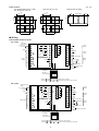
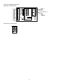
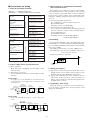
No. CP–SS–1679E DigitroniKTM Digital Indicating Controller SDC40B ■ Features The Digitronik SDC40B is a single loop digital indicating controller for controlling temperatures, pressures, flow rates, levels, PH values, etc. A compact instrument with PID control and various auxiliary functions, it offers instrumentation with a high level of cost performance. A PC loader allows the user to design any combination of functions ■ A host of I/O functions ● ● ● ● ● ● ● ● ■ Functions ● ● ● ● ● ● ● ● ● ● ● ● Four types of controllers combined with numerous computational units allow not only local control and cascade control, but feed forward control, non-linear control, dead time compensation control, override control and more. In addition to conventional PID auto-tuning, the following three functions can be selected and combined (only normal PID computation mode): • PID with two degrees of freedom: • Independent rising edge characteristics PID and disturbance response characteristics PID functions are provided and are automatically switched through the use of fuzzy rules. • Smart tuning: Helpful in suppressing overshoots • Neural network: Supports a wide-range of response characteristics and automatically finetunes constants. Approximately 80 computational expressions (addition, subtraction, multiplication, division, selector, linearization table, etc.) A total of 50 computational units can be assigned. An auto balance function prevents output shear for smooth mode switching. Analog input errors and computational errors can be detected and an interlock function is available. ■ Easy to configure and operate Inputs ............ Analog inputs : 3 Digital inputs : 12 Outputs ......... Analog outputs : 3 (5G), 2 (2G) Digital outputs : 8 Number of computational expressions: Approx. 80 Number of computational units: 50 Variable parameters ......... %: 40, Time: 10, Flag: 20, Index: 10 Fixed parameters unlimited number Number of PID units: Up to 2 units Number of parameter groups: 8 Engineering unit parameters: 8 per PID, a total of 16 Linearization tables: 3 tables (connectable), 16 points per table PTB (% → %) tables: 4 tables with 16 points per table that can be used as linearization tables TTB (% → time) tables: 4 tables with 16 points per table ● ● ● Configurations (combining computational units) can be simplified with the use of a PC loader. Two user definable function keys each of which can store up to 8 data items. Trends can be monitored on a PC loader. ■ Block Diagram Input processing data Digital input processing Input processing Analog input block AIR 1 AIR 2 AIR 3 Digital input DI 1 DI 2 DI Computational unit data (Up to 50 combinations) Computation processing blocks Up to 50 computational units 1 Computational Computational unit unit 50 Computational unit Computational unit Output processing Output processing Analog output block AO 1 Motor feedback (2G output) AO 2 AO 3 Digital output DO 1 DO 2 Output processing ● ■ A great number of control functions Three analog inputs • Input 1: Thermocouple, RTD (resistance temperature detector), DC voltage and DC current • Input 2: 4 to 20mAdc or 1 to 5Vdc • Input 3: 1 to 5Vdc Capable of accepting and processing the following inputs: Approximation by linearization table, temperature and pressure compensation, and square-root extraction. 12 digital inputs • No-voltage contact (relay contact) or open collector • The digital input processor can convert data to 2n index data. • In addition to mode switching and selections, the controller can be directly linked to internal processing. Three (5G) and two (2G) analog outputs • 5G output: 4 to 20mAdc (3 analog outputs) • 2G output: M/M driven relay (1 analog output) 4 to 20mAdc (1 analog output) 8 digital outputs • SPST relay outputs (2 digital outputs), SPDT relay output (1 digital output), open collector outputs (5 digital outputs) • Results of internal processing can be assigned to any output. Input processing ● DO 8 12 Computational expressions (90) Linearization data 1 Variable parameters Engineering unit parameters Control computatonal data PID parameters Setup data Project UF key processing data Trend processing data ■ Specifications Performance specifications Analog input 1 Type of inputs Multirange indication of thermocouple, RTDs, and DC voltage/currents (See Table 1.) (AIR 1) Input indicating accuracy ±0.1% FS ±1U (This may be affected by indication value conversion and ranges under standard conditions) Input sampling cycle 0.1 to 0.5 sec. (depends on computation cycle) Input bias current Thermocouple and DC voltage input : ±1.3µA max. (peak value under standard conditions) Range above 1V or more, -3µA Input impedance DC current input: 50Ω ±10% (under operating conditions) Measuring current RTD: 1.04mA, ±0.02mA, Current input on terminal A. (under operating conditions) Effect of wiring resistance Thermocouple, DC current and DC voltage : Variation in indicated value due to input conversion when the wiring resistance at both ends is 250Ω • 0 to 10mV, -10 to +10mV : 35µV or less • 0 to 100mV, : 60µV or less • Others : 750µV or less RTD: ±0.01% FS/Ω max. in a wiring resistance range of 0 to 10Ω ±0.02% FS/Ω max. in a range with a minimum resolution of 0.01°C The allowable wiring resistance is 85Ω max (A zener barrier is available only for the 0.1°C resolution range and requires on-site adjustment.) Allowable parallel resistance Allowable parallel resistance for thermocouple break detection : 1 MΩ or more Maximum allowable input Thermocouple and DC voltage input : -5 to +15V DC current input : 28mA Burnout Internal upscale and downscale selection Over range detection threshold 110% FS or more : Upscaled -10% FS or less : Downscaled (However, inputs in the -200.0 to +500.0°C range of JIS Pt100 and the -200.0 to +500.0°C range of JIS Pt100 are not downscaled. The indicating values lower limit for B input (0.0 to 1800.0°C) is 20°C .) Cold junction compensation accuracy ±0.5°C (under standard conditions) Cold junction compensation method Internal or external compensation (at 0°C) selectable Scaling -19999 to ±26000U (These settings are available for linear inputs only. Reverse scaling and decimal point repositioning can be performed with resolutions to 1/20000.) Analog input 2 Type of inputs 4 to 20mAdc, 1 to 5Vdc (See Table 1.) (AIR 2) Input indicating accuracy ±0.1% FS ±1U (display value conversion under standard conditions) Input sampling cycle 0.1 to 0.5s (depends on computation cycle) : ±10µA max. (under operating conditions) Input bias current 1 to 5Vdc input Input impedance 1 to 5Vdc input : 1MΩ or more (under operating conditions) 4 to 20mAdc input : 50Ω ±10% (under operating conditions) Maximum allowable input 1 to 5Vdc input 4 to 20mAdc input Burnout Downscale Over range detection threshold 110% FS or more : Upscaled -1 0% FS or less : Downscaled Scaling -19999 to +26000U (Reverse scaling and decimal point repositioning can be performed with resolutions to 1/20000.) : 0 to 6V : 28mA Analog input 3 Type of inputs 1 to 5Vdc (See Table 1.) (AIR 3) Input indicating accuracy ±0.1% FS ±1U (display value conversion under standard conditions) Input sampling cycle 0.1 to 0.5 sec. (depends on computation cycle) Input bias current ±10µA max. (under operating conditions) Input impedance 1 MΩ or more (under operating conditions) Maximum allowable input 0 to 6V Burnout Downscale Over range detection threshold 110% FS or more : Upscaled -10% FS or less : Downscaled Scaling -19999 to +26000U (Reverse scaling and decimal point repositioning can be performed with resolutions to 1/20000.) 2 Digital input No. of inputs 12 points (DI 1 to DI 12) Types of connectable outputs No-voltage contacts (relay contacts) and open collector (current sink to ground) Terminal voltage (open) 12V +0.5V –1.5V (under operating conditions) across common terminal (terminal 25 )and each input terminal. Terminal current (short-circuited) 6mA +0.6mA –1.0mA (under operating conditions) across each terminal Allowable contact resistance (no-voltage contact) On: 700Ω or less (under operating conditions) Off: 10Ω or more (under operating conditions) Residual voltage (open collector on) 3V or less (under operating conditions) Leakage current when an open collector is off 0.1mA or less (under operating conditions) Parallel connection to other instruments Can be connected to Yamatake SDC40B series instruments Input sampling cycle 0.1 to 0.5 sec. (depends on computation cycle) ON detection min. hold time 0.2 to 1.0 sec. (double computation cycle) Input processing block As shown below, the controller can accept and process five analog inputs: approximation by 1 linearization table, 2 temperature compensation, 3 pressure compensation, 4 square-root extraction and 5 digital filtering. Raw inpu data AIR 1 AIR 2 AIR 3 Linearization TBL TBL TBL Temp. comp. T.COMP T.COMP T.COMP Press. comp. Sq.-root extraction Digital filtering P.COMP P.COMP P.COMP SQRT SQRT SQRT DIG. FILT DIG. FILT DIG. FILT Input processing functions Raw input data Linearization Flow rate 0 signals Temp. comp. TBL 1 AIR 3 TBL 2 Press. comp. Sq.-root extraction 0 0 0 1 1 1 TBL 3 T.COMP Input processing AI 1 Input processing AI 2 P.COMP Filtering Processed inputs DIG. FILT AI 3 SQRT Temp. signals AIR 1 Press. signals Processed inputs AI 1 AI 2 Linearization AIR 2 AI 3 Three sets of 16 approximation by linearization tables are provided. They can be assigned to analog inputs 1, 2 and 3. Temperature compensation (T. COMP) Compensation flow rate signal = design (target) temperature + constant current temperature + constant × flow rate signal °C or °F can be selected as units. Pressure compensation Compensation flow rate signal = (P. COMP) current pressure + constant design (target) pressure + constant × flow rate signal 2 MPa, kPa, Pa, kgf/cm or mmH 2O can be selected as units. Square-root extraction (SQRT) Digital filtering Dropout value: 0.0 to 100.0% variable First order lag computation: Output = (DIG. FILT) 1 1+T×S × input T: Filter constant 0.0 to 120.0 sec (no filtering at 0.0) S: Laplacian Computation processing block About 80 computational expressions can be assigned to a total of 50 computational units. Each computational expression has the following format and can operate on up to 4 inputs. Refer to the list of computational expressions for details. OUT= f (H1, H2, P1, P2) Example 1: Addition H1 H2 Example 2: ON delay timer Example 3: Integration pulse output II H1 H1 H2 terminal: % data terminal: Time data ADD P1 P1 ONDT CPX P2 OUT (OUT=P1×H1+P2×H2) OUT P1 terminal: Flag data P2 terminal: Index data OUT (OUT asserted after P1 completes) 3 (Integration performed on input H1 and pulse output as per integral range specified by H2 and P1.) Computation Processing book Computation cycle setting 0.1 to 0.5 sec. (Settable in 0.1 sec. increments.) PID control and output unit Performed by PID computational unit 1 (PID 1) or PID computational unit 2 (PID 2) in the computational expressions. Of the 50 computational units only one each can be assigned as computational units 1 and 2. Control type PID computational unit 1 (PID 1) Type 0 Local setting Not used Type 1 Remote/Local setting Not used Type 2 Remote/Local setting Remote setting Type 3 Local setting Remote/Local setting Control output model No. Output processor Analog output (A01 to A03) PID computational unit 2 (PID 2) 2G Type 0 to 3 are set at setup. Only one MAN computational unit can be used for two PID computational units. 5G Analog output A01 M/M drive relay contact output Current output (4 to 20mAdc) A02 None Current output (4 to 20mAdc) signal A03 Current output (4 to 20mAdc) Current output (4 to 20mAdc) Control operation Position proportional PID and current proportional PID Current proportional PID Computation mode Normal or derivative-based is selectable using PID computational units. Proportional band (P) 0.1 to 999.9% (ON/OFF disabled) Integral time 0.0 to 6000.0 sec. (PD activates at I = 0) Derivative time (D) 0.0 to 6000.0 sec. (PI activates at D = 0) Integral limit (I) Lower limit: -200.0 to upper integral limit %, Upper limit: Lower integral limit to 200.0% Dead band 0.0 to 100.0% (no dead band at 0) Output deviation rate limit 0.0 to 100.0% / Computation cycle (no limit at 0) Manual reset 0.0 to 100.0% No. of PID groups 8 groups (shared by PID computational units 1 and 2) PID auto-tuning (Only normal PID computation mode) Neuro, fuzzy (with two degrees of freedom) and smart methods are used in addition to the limit cycle method to set PID auto-tuning. RSP ratio -999.9 to +999.9% of RSP of PID computational units 1 and 2 RSP bias -999.9 to +999.9% of RSP of PID computational units 1 and 2 Deviation alarm 0.0 to 100.0% of |SP-PV|, the absolute value of PID computational units 1 and 2 Upper PV alarm limit -10.0 to +110.0% of PV of PID computational units 1 and 2 Lower PV alarm limit -10.0 to +110.0% of PV of PID computational units 1 and 2 Alarm hysteresis 0.0 to 100.0% for deviation alarm, upper PV alarm limit and lower PV alarm limit Model No. 2G AO1 M/M drive relay contact output Contact system Contact rating : 2SPST : 2.5A (30Vdc L/R = 0.7ms) 4A (120Vac cos ø = 0.4) 2A (240Vac cos ø = 0.4) Allowable contact voltage : 250Vac resistive load, 125Vdc resistive load, 125Vdc L/R = 0.7ms 250Vac cos ø = 0.4 Maximum on-off power : 75W (L/R = 0.7ms), 480VA (cos ø = 0.4) Mechanical life : 10,000,000 repetitions Electrical life : 100,000 repetitions (cos ø = 0.4 at contact rating and 30 repetitions per minute) Minimum switching voltage : 5V Minimum switching current : 100mA MFB (motor feedback) input range : 100 to 2500Ω MFB (motor feedback) line-break control : Whether action is continued is determined by MFB estimated position setting. Model No. 2G AO3 Current output (4 to 20 mA) Current output : Allowable load resistance : Output accuracy : Output resolution : Inrush current : Maximum output current : Minimum output current : Opening terminal voltage : Output update cycle : Model No. 5G AO1, AO2, AO3 4 4 to 20mAdc 680Ω or less (under operating conditions) ±0.1% FS or less (under operating conditions) 1/10000 25mA or less, 50ms or less (with 250Ω load) 21.6mAdc 2.4mAdc 25V or less 0.1 to 0.5 sec. (depends on computation cycle) Output processing block Digital output (DO1 to DO8) D01 SPST relay contact Electric rating: 250Vac, 30Vdc, 1A resistive load Mechanical life: 20,000,000 repetitions Electrical life: 100,000 repetitions (at rated capacity) Minimum switching voltage: 10V Minimum switching current: 10mA D03 SPST relay contact Electric rating: 250Vac, 30Vdc, 2A resistive load Mechanical life: 50,000,000 repetitions Electrical life: 100,000 repetitions (at rated capacity) Minimum switching voltage: 10V Minimum switching current: 10mA D04 to D08 Open collector External supply voltage: 10 to 29Vdc Maximum load current: 70mA per point Leakage current when off: 0.1mA D02 Indications and settings Modes Display panel 1 Green 5-digit, 7-segment LED This panel normally displays values. Item codes are displayed in control data setting mode and alarm codes are displayed when alarms are generated. Display panel 2 Orange 5-digit, 7-segment LED This panel normally displays SP values. Set values are displayed in control data setting mode. Display panel 3 Orange 2-digit, 7-segment LED This panel displays the difference between LSP and RSP values in normal indicating mode when display panel 2 shows SP values. In control data setting mode, item codes are displayed. LED bar display 12 green and amber LEDs Analog monitor (includes control output) which doubles as a digital monitor. Status display 18 LEDs SP, LCK, OUT, CH1 (PID computational unit 1), CH2 (PID computational unit 2), FLW (follow mode), AUT (auto mode), MAN (manual mode), CAS (cascade mode), IM (interlock manual mode), AT (auto-tuning), FZY (during fuzzy switching), OUT1, OUT2, OUT (bar graph control output), UF1,UF2, UF3 (user defined) Operation keys 13 rubber keys (of which two are user definable) Loader connecting port 1 (dedicated cable with stereo miniplugs) Normal operating mode Auto mode PID computational units control constants (LSP). Manual mode MAN computational units output manual settings. (However, only one MAN computational unit can be used.) Only PID computational units perform integral operations. Cascade mode PID computational units control cascade settings (RSP). Follow mode Communications MAN computational units outputs follow inputs to the SDC40B. Emergency operating mode Interlock manual mode: This mode is activated when an analog overflow, computational overflow or computational overload is detected Communications system Communications standard Network Interface system Display characters Isolation RS-485 Multidrop (SDC40B provided with only slave node functionality) 1 to 16 units or less (DIM), 1 to 31 units or less (CMA, SCM) RS-232C Point-to-point (SDC40B provided with only slave node functionality) Data flow Half duplex Half duplex Synchronization Start-stop synchronization Start-stop synchronization Transmission system Balanced (differential) Unbalanced Data line Bit serial Bit serial Signal line 5 transmit/receive lines (3-wire connection is also possible.) 3 transmit /receive lines Transmission rate 4800, 9600bps 4800, 9600bps Transmission distance 500m max. (total) (300m for MA500DM connection) 15m max. Misc Comforms to RS-485 standard Comforms to RS-232C standard Char. bit count 11 bits per character 11 bits per character Format 1 start bit, even parity, 1 stop bit; or 1 start bit, no parity, and 2 stop bits 1 start bit, even parity, 1 stop bit; or 1 start bit, no parity, and 2 stop bits Data length 8 bits 8 bits Input and output are completely isolated. Note 1 : RS-485 communications can be performed by connecting to a computer equipped with an RS-485 interface or Yamatake MX200, MA500 AH (DK link II DIM) or CMA50 controllers. 5 General specifications Memory backup User settings (design data and control data): Non-volatile semiconductor memory (EEPROM) Mode, local SP, control output (AO1) and hold computations: RAM backed up by super-capacitor (stored for 24 hours) Rated power voltage AC model 100 to 240Vac 50/60 hz DC model 24Vdc Allowable power supply voltage AC model 90 to 264Vdc 50/60 Hz DC model 21.6 to 26.4Vdc Power consumption AC model 30 VA max. DC model 12W max. Power switching inrush current 15A max. for (under operating conditions) Note: When starting up a number of SDC 40B, simultaneously, ensure ample power is supplied or stagger their startup times. Otherwise the controllers may not start normally due inrush current induced-voltage drop. Voltage must stabilize within 2 seconds after power on. Power ON operation Reset time: 15 sec. max. (time until normal operation possible under normal operating conditions) Allowable transient power loss AC model 20ms min. (under operating conditions) DC model No power failure allowed. Power failure recovery operations Hot start or cold start selectable (see below) Selection Hot start Cold start RAM backup Local SP During normal operation Hot start Before outage Before outage Before outage During failure Preset mode Preset LSP Preset value Cold start Controloutput (AO1) N/A not applicable Min. 20MΩ or more between power terminal 1 or 2 and ground terminal 3 (using a 500Vdc megger). Dielectric strength AC model 1500Vac 50/60 Hz for 1min across power terminal and ground terminal 1500Vac 50/60 Hz for 1min across relay output and gruond terminal 500Vac 50/60 Hz for 1min across non-power terminal and ground terminal 500Vac 50/60 Hz for 1min across isolated terminal DC model 500Vac 50/60 Hz for 1min across power terminal and ground terminal 1500Vac 50/60 Hz for 1min across relay output and gruond terminal 500Vac 50/60 Hz for 1min across non-power terminal and ground terminal 500Vac 50/60 Hz for 1min across isolated terminal Ambient temperature 23 ± 2°C Ambient humidity 60 ± 5% RH AC model 105Vac ± 1% DC model 24Vdc ± 5% Power frequency AC model 50 ± 1Hz or 60 ± 1Hz Vibration resistance 0m/s2 Impact resistance 0m/s2 Rated power voltage Operating conditions Shipping and storage conditions Related Publications Description Mode Insulation resistance Standard conditions Standard accessories Actual outage recovery process Mounting angle Reference plane (vertical) ± 3° Ambient temperature range 0 to 50°C Ambient humidity range 10 to 90% RH (non-condensing) Rated power voltage AC model: 100 to 240Vac Power frequency AC model: 50 ± 2Hz or 60 ± 2Hz Vibration resistance 0 to 1.96m/s2 Impact resistance 0 to 9.81m/s2 Mounting angle Reference plane (vertical) ±10° Installation mode Parmanently connected type controller, indoor installation, panel-mounted Application standards EN61010-1, EN 61326 (CE statement) Over-voltage category Category II (IEC60364-4-443, IE60664-1) Pollution degree 2 Altitude 2000m max. Ambient temperature range -20 to 70°C Ambient humidity range 10 to 95% RH (non-condensing) Vibration resistance 0 to 4.90m/s2 (10 to 60Hz for 2 hours each in X, Y and Z directions) Impact resistance 0 to 4.90m/s2 (3 times vertically) Package drop test Drop height: 90cm (1 angle, 3 edges and 6 planes; free fall) Materials of mask and case Mask: Multilon Colors of mask and case Mask: dark gray Installation Specially designed mounting bracket Weight (Mass) Approx. 900g Parts name DC model: 24Vdc Parts number Case: Polycarbonate Case: Light gray Quantity Options Parts name Parts number Unit indicating label N-3132 1 Hard dust-proof cover set 81446083-001 Mounting bracket 81405411-001 2 Soft dust-proof cover set 81 446087-001 User’s manual: Basic Operations CP-UM-1679E 1 Terminal cover set 81446084-001 Smart Loader package SLPC4B-001H User’s manual: Computational Functions CP-UM-1680E User’s manual: CPL Communication Functions CP-UM-1683E 6 Table 1. Input types and ranges (selected at setup) Input 1 Thermocouples, RTDS, DC current and DC Voltage °C range Symbol °F range °C range Symbol K (CA) 0.0 to 1200.0 0 to 2400 K (CA) 0.0 to 800.0 0 to 1600 K (CA) 0.0 to 400.0 0 to 750 JIS ’89 JPtl00 °F range -200.0 to +500.0 -300.0 -200.0 to +200.0 -300.0 to +900.0 to +400.0 -100.0 to +150.0 -150.0 to +300.0 K (CA) -200.0 to +1200.0 -300 to +2400 -50.0 to +200.0 -50.0 to +400.0 K (CA) -200.0 to +300.0 -300 to +700 -60.0 to +40.0 -76.00 to +104.00 K (CA) -200.0 to +200.0 -300 to +400 -40.0 to +60.0 -40.00 to +140.00 0.0 to 800.0 0 to 1800 0.0 to 500.0 0.0 to +900.0 E (CRC) J (IC) 0.0 to 800.0 0 to 1600 0.0 to 300.0 0.0 to +500.0 -200.0 to +300.0 -300 to +700 0.00 to 100.00 0.00 to +200.00 B (PR30-6) 0.0 to 1800.0 0 to 3300 4 to 20mA R (PR13) 0.0 to 1600.0 0 to 3100 0 to 20mA S (PR10) 0.0 to 1600.0 0 to 3100 0 to 10mA -19999 to +26000 W (WRe5-26) 0.0 to 2300.0 0 to 4200 –10 to +10mA (Decimal point repositioning W (WRe5-26) 0.0 to 1400.0 0 to 2552 0 to 1V and reverse scaling possible.) PR40-20 0.0 to 1900.0 0 to 3400 –1 to +1V T (CC) Ni-Ni · Mo 0.0 to 1300.0 32 to 2372 1 to 5V N 0.0 to 1300.0 32 to 2372 0 to 5V PL II 0.0 to 1300.0 32 to 2372 0 to 10V -200.0 to +400.0 -300 to +750 +1600 DIN U DIN L Input 2 DC current and DC voltage -200.0 to +800.0 -300 to -200.0 to +500.0 -300.0 to +900.0 Input format JIS ’89 Ptl00 -200.0 to +200.0 -300.0 to +400.0 4 to 20mA (IEC Pt100Ω) -100.0 to +150.0 -150.0 to +300.0 -50.0 to +200.0 -50.0 to +400.0 -60.00 to +40.00 -76.00 to +104.00 -40.00 to +60.00 -40.00 to +140.00 500.0 0.0 to 900.0 0.0 to 0.0 to 0.00 to 300.0 0.0 to 500.0 100.00 0.0 to 200.00 Scale setting range: 1 to 5V Range Scale setting range: -19999 to +26000 (Decimal point repositioning and reverse scaling possible.) Input 3 DC voltage Input format 1 to 5V Range Scale setting range: -19999 to +26000 (Decimal point repositioningand reverse scaling possible.) ● Items that do not meet stated indication accuracy (±1% FS ±1U) • RTDs: ±0.15% FS ±1U for the range below 2 decimal places ±0.15% FS ±1U for the range 0 to 10mV • DIN U thermocouples: ±2.0°C ±1U for temperatures below -100°C ±1.0°C ±1U for temperatures ranging from -100 to 0°C • DIN L thermocouples: ±1.5°C ±1U for temperatures below -100°C • K and T thermocouples: ±1°C ±1U for temperatures below -100°C • B thermocouples: ±4.0% FS ±1U for temperatures below 260°C ±0.4% FS ±1U for temperatures ranging from 260 to 800°C ±0.2% FS ±1U for temperatures ranging from 800 to 1800°C • R and S thermocouples: ±0.2% FS ±1U for temperatures below 100°C ±0.15% FS ±1U for temperatures ranging from 100 to 1600°C • PR40 -20 thermocouples: ±2.5% FS ±1U for temperatures below 300°C ±1.5% FS ±1U for temperatures ranging from 300 to 800°C ±0.5% FS ±1U for temperatures ranging from 800 to 1900°C Data andsetting procedures Category Design data Control data : can be set : can sometimesbe set Data Computational unit data : can be monitored Description — : cannot be set or monitored From console Specifies computational expressions, connections, etc. Output processing data Specifies output processing connections Setup data Specifies control types and computation cycles Input processing data Specifies input processing types, etc. Control Computational data Specifies PID computation modes, PID groups to be used, etc. PID parameters Specifies control parameters for PID groups 0 to 7 Linearization data Specifies linearization format Variable parameters Specifies computation coefficients, constants, etc. Engineering unit parameters For setting engineering units UF key processing data Specifies functions assigned to user function keys (UF) 1 and 2 Digital input processing data Used as DI1 to DI12 index data ID data Identifiers for hardware type, ROM and others not in EEPROM Protector Specifies key lock, etc Trend processing data Specified when using data trend functions on PC loader 7 — From PC loader List of computationalexpressions No. Computational expressions Symbol Description 1 Addition ADD OUT=P1×H1+P2×H2 2 Subtraction SUB OUT=P1×H1–P2×H2 3 Multiplication MUL OUT=H1×H2 4 Division DIV OUT=H1/H2+P1 5 Absolute Value ABS OUT=H1 6 Square-Root Extraction SQR OUT= √H1 7 Maximum Value MAX OUT=MAX (H1, H2, P1, P2) 8 Minimum Value MIN OUT=MIN (H1, H2, P1, P2) 9 4-point Addition SGM OUT=H1+H2+P1+P2 10 High Selector/Low Limiter HSE When H1 ≥ H2, OUT is H1. When H1 < H2, OUT is H2. When used as a low limiter, H2 is the lower limit value. 11 Low Selector/High Limiter LSE When H1 ≥ H2, OUT is H1. When H1 < H2, OUT is H2. When used as a low limiter, H2 is the lower limit value. 12 High and low limiter HLLM H1 is limited by the high limit value P1 and the low limit value P2. 13 High Monitor HMS Output is asserted when H1 exceeds high monitor value H2. (Hysteresis width is P2.) 14 Low Monitor LMS Output is asserted when H1 falls below the low monitor value H2. (Hysteresis width is P2.) 15 Deviation Monitor DMS Output is asserted when the deviation between H1 and H2 exceeds deviation monitor value P1. (Hysteresis width is P2.) 16 Deviation Rate Limiter DRL Limits input H1s deviation rate per minute to H2% on positive side and to P1% on the negative side. 17 Deviation Rate Monitor DRM Output is asserted when input H1 exceeds H2% on positive side and is within P1% on negative side compared to inputs made one minute earlier. 18 Manual Output MAN Enables manual output from system console. 19 Controller #1 P1D1 PID controller 1 (with auto-tuning) 20 Controller #2 P1D1 PID controller 2 (with auto-tuning) 21 Dead Time DED OUT=e-P1 · S × H1(Input H1, the dead time, is output after P1 seconds.) 22 Lead/Lag L/L OUT=(1+P1 · S) / (1+P2 · S)×H1 23 Derivative LED OUT=P1 · S(1+P2 · S)×H1 24 Integral INT OUT=H1/P1 · S (Integration performed on input H1 in integral time of P1 seconds.) 25 Moving Average MAV 1 OUT= 30 30 ΣH i=1 1 i ( 30 P1) 26 Flip-Flop RS Set input H1 holds flag data; H2 input resets the data. 27 Logical Product AND OUT=H1 H2 P1 P2 28 Logical OR OR OUT=H1 H2 P1 P2 29 Exclusive OR XOR OUT=H1— GH2 30 Invert NOT OUT=H1 31 2-Position Transfer Switch SW P1 switches between H1 and H2 percent data. 32 Softening Transfer Switch SFT Switches between H1 and H2 using a P2 (%) slope for smooth switching. 33 Timer switch TSW Switches between H1 and H2 using P1 time data, 34 Flag switch FSW Switches between H1 and H2 using P1 flag data. 35 Alternate switch ALSW Inverts output when the rising edge of H1 is detected. 36 Timer TIM Pulse generation per P1 seconds. 37 On delay timer ONDT Asserts output aftter P1 seconds. 38 Off delay timer OFDT Inhibits output after P1 seconds. 39 One-shot timer OST Generates pulse for P1 seconds. 40 Integration pulse output 1 CPO Outputs the number of pulses proportional to input H1. 41 Integration pulse output II CPX Performs integration on input H1 and outputs one pulse when the output pulse value set by P1 is reached. 42 Pulse width modulation PWM Asserts output in proportion to input H1 within the P1 cycle. 43 Ramp signal RMP Outputs a waveform with a rising slope. 44 LOG LOG OUT=LOG10 (H1) or OUT=LOGe (H1) 45 Exponent EXP OUT=10H1 or OUT=eH1 46 (Not used) 47 (Not used) 48 (Not used) 49 (Not used) 50 (Not used) 51 Control variable change #1 PMD1 Changes PID 1 control variables, (enables changing of PID group numbers also.) 52 Control variable change #2 PMD2 Changes PID 2 control variables, (enables changing of PID group numbers also.) 53 Mode select (status detection) MOD Cycles through follow, manual, auto and cascade modes 54 Mode select (edge detection) MODX Cycles through follow, manual, auto and cascade modes 55 Auto-tuning start/stop 1 AT1 Starts/stops PID 1 unit auto-tuning. 56 Auto-tuning start/stop 2 AT2 Starts/stops PID 2 unit auto-tuning. 57 Data hold HOLD Retains input H1 during outage, and outputs it as is after restore. 58 Raise lower unit RL Raises output when H1 is ON (raise) and lowers it when H2 is ON (lower). 59 Reset unit RST Resets the interlock manual mode. 60 (Not used) 61 Linearization Table #1 TBL1 Linearization Table #1 (16 points) 62 Linearization Table #2 TBL2 Linearization Table #2 (16 points) 63 Linearization Table #3 TBL3 Linearization Table #3 (16 points) 8 No. Computational expressions Symbol Description 64 Inverse linearization Table #1 TBR1 Inverse function of linearization Table #1 (16 points) 65 Inverse linearization Table #2 TBR2 Inverse function of linearization Table #2 (16 points) 66 Inverse linearization Table #2 TBR2 Inverse function of linearization Table #3 (16 points) 67 Time → % conversion TTP Converts time data to percent data. 68 % → Time conversion PTT 69 Engineering unit parameter selection #1 E _P1 Selects engineering unit parameters for PID 1 units. 70 Engineering unit parameter selection #2 E _P2 Selects engineering unit parameters for PID 2 units. 71 (Not used) 72 (Not used) 73 (Not used) 74 (Not used) 75 (Not used) 76 (Not used) 77 (Not used) 78 (Not used) 79 (Not used) 80 (Not used) 81 % → % table #1 PTB1 Not connectable, but otherwise identical to linearization tables. 82 % → % table #2 PTB2 Not connectable, but otherwise identical to linearization tables. 83 % → % table #3 PTB3 Not connectable, but otherwise identical to linearization tables. 84 % → % table #4 PTB4 Not connectable, but otherwise identical to linearization tables. 85 % → time table #1 TTB1 Uses linearization table to convert % data to time data. 86 % → time table #2 TTB2 Uses linearization table to convert % data to time data. 87 % → time table #3 TTB3 Uses linearization table to convert % data to time data. 88 % → time table #4 TTB4 Uses linearization table to convert % data to time data. 89 (Not used) Converts percent data to time data. 90 (Not used) 91 User lamp ouput #1 UF1 User lamp control unit #1 92 User lamp ouput #2 UF2 User lamp control unit #2 93 User lamp ouput #3 UF3 User lamp control unit #3 94 Bar graph display switch BLED Selects bar graph display. 95 Additional display unit #1 DSP1 Additional display unit #1 of display panels 1 and 2 96 Additional display unit #2 DSP2 Additional display unit #2 of display panels 1 and 2 97 Additional display unit #3 DSP3 Additional display unit #3 of display panels 1 and 2 98 Additional display unit #4 DSP4 Additional display unit #4 of display panels 1 and 2 99 (Not used) ■ Model Selection Guide Example: C40B5G4AS09100 Basic Model No. Control Function output Power supply Options Options Additional 1 2 Processing C40B Specifications Digital indicating controller 2G Position proportional output 5G Current output (4 to 20mAdc / 0 to 20mAdc) 4 Input 1: Thermocouples, RTDs, DC current, DC voltage of multi-range Input 2: 4 to 20mAdc, 1 to 5Vdc Input 3: 1 to 5Vdc AS AC power supply (90 to 264Vac: Free power supply) DS DC power supply (21.6 to 26.4Vdc) 06* 1 auxiliary output, 12 digital inputs, 8 digital outpus (3 relays, 5 open collectors) 09* 2 auxiliary outputs, 12 digital inputs, 8 digital output (3 delays, 5 open collectors) 1 No xommunication interface 2 RS-485 communications 3 RS-232C communications 00 Additional processing not provided T0 Tropical treatment K0 Antisulfide treatment D0 Inspection certificate provided B0 Tropical treatment + inspection certificate provided L0 Antisulfide treatment + inspection certificate provided Y0 Complying with the traceability certifications * An option 06 can specify only at the time of control output 2G. An option 09 can specify only at the time of control output 5G. 9 ■ Dimensions (Unit: mm) SDC40B instrument Terminal cover set (option) 81446084-001 (18) Hard dust-proof cover set (option) 81446083-001 15 159.5 137 96 A B A—A RLW CAS CH1 AUT CH2 IM MAN SP LCK OUT AT EZY DISP MAN AUTO CAS PARA LOADER AT ENT 26 12 22 27 3 13 23 28 4 14 24 29 5 15 25 30 6 16 31 7 17 32 8 18 33 9 19 34 10 20 M3.5 terminal screw Lock screw A M3.5 terminal screw B Mounting bracket 81405411-001 Soft dust-proof cover set (option) 81446087-001 B—B 26 1 41 49 57 42 50 58 4 43 51 59 29 5 44 52 60 30 6 45 53 61 31 7 46 54 62 32 47 55 63 48 56 64 2 91.5 3 8 9 27 28 33 34 10 37 78.4 Soft dust-proof cover set: Parts No. 81446087-001 Terminal cover set: Parts No. 81446087-001 [Installable on standard and expanded terminal bases] (Transparent silicon rubber) (Transparent silicon rubber) 15 90 12 45 Hole 5-3.6 5.5 17 13.7 (3.2) 98 1.5 (0.5) (86) 79 2.7 Hard dust-proof cover set: Parts No. 81446087-001 (Transparent silicon rubber) 16 6 106 4 96.6 96.6 106 (96.8) 1.1 4.7 4.7 8 10 90 51.6 98 95 14 29.5 69.6 +0.2 R1.8 —0.1 110.5 OT2 UF2 21 2 90.2 OT1 UF1 96 UF1 UF2 UF3 (106×104) OUT 1 11 Panel cutout (Unit: mm) For standard application or with soft dust-proof cover set Hard dust-proof cover 92 +0.8 0 (N—1)×96 46 150 min. 92 +0.8 0 92 +0.8 0 46 150 min. 92 +0.8 0 92 +0.8 0 Side-by-side mounting N×96—4 (N: number of units installed) 107 min. 99 min. ■ Wiring ● Standard terminal layout AC model Instrument power supply 2G 5G 1 90 to 264Vac 50/60Hz 21 11 DI1 26 4 to 20mAdc GND 2 12 3 13 Y 4 4 to 20mAdc DO1 T 5 AO1, AO2 14 22 DI2 27 23 DI3 28 24 DI4 29 25 15 Analog input 3 1 to 5Vdc + 4 to 20mAdc Analog input 2 1 to 5Vdc COM 30 G 6 31 16 mAdc Current input DO2 Digital outputs 7 DO3 32 17 4 to 20mAdc RTD input AO3 8 18 9 19 33 34 V, mV Voltage input * 10 Analog input 1 20 Thermocouple input Auxiliary outputs 4 to 20mA Recorder or other instrument * Terminals 17 and 18 are the auxiliary outputs for the 2G model Terminals 14 and 15 or 17 and 18 are the auxiliary outputs for the 5G model. DC model Instrument power supply 2G 5G 11 21 DI1 26 2 12 22 DI2 27 3 13 23 DI3 28 24 DI4 29 1 21.6 to 26.4Vdc 50/60Hz GND 4 DO1 5 Analog input 3 1 to 5Vdc 4 to 20mAdc Y AO1, AO2 14 4 to 20mAdc T 25 15 COM 4 to 20mAdc Analog input 2 1 to 5Vdc 30 G 6 31 16 mAdc Current input DO2 Digital outputs 7 DO3 32 17 4 to 20mAdc RTD input AO3 8 18 9 19 34 * 10 Analog input 1 33 V, mV Voltage input 20 Thermocouple input Auxiliary outputs 4 to 20mA Recorder or other instrument * Terminals 17 and 18 are the auxiliary outputs for the 2G model Terminals 14 and 15 or 17 and 18 are the auxiliary outputs for the 5G model. 11 Layout of expanded terminals ● RS-485 communications 41 DI 5 DI 6 42 DI 7 43 DO4 DO5 DO6 DO7 Load 49 57 SDA Load 50 58 Load 51 59 Load 52 60 Load 53 61 DI 8 44 DI 9 45 DI10 46 54 DI11 47 55 DI12 48 56 DO8 62 Bias circuit 63 To terminal 25 64 External power supply 10 to 29Vdc ● RS-232C communications 59 RD 60 61 SD SG 12 SDB RDA RDB SG External communications ■ Precautions on wiring 3. Noise sources in installation environment and countermeasures The following are possible noise sources in the installation environment: relays, contacts, magnetic coils, solenoid valves, power lines (especially 90Vac or above), inductive loads, inverters, motor rectifiers, phase control SCR, radio equipment, welding equipment, high-voltage ignition devices, etc. (1) Counteracting quick rising noise Use a CR filter to counteract quick rising noise. Recommended filter: Yamatake part No.: 81446365-001 (2) Counteracting noise with high peaks Use a varistor to counteract noise with high peaks, but note that a defective varistor is short-circuited and has to be handled with care. Recommended varistor: Yamatake part No.: 81446366-001 (100Vac) 81446367-001 (200Vac) 1. Internal instrument isolation Solid line (——) indicates isolated area. Dashed line (......) indicates areas that are not isolated. Input 1 (AR1) (full multi) Analog output 1 (A01) (control output 4 to 20mA) Analog output 2 (AO2) (auxiliary output 4 to 20mA) ......................................... Input 3 (AIR3) (1 to 5V) ......................................... Loader communication I/O Digital circuits Input 2 (AR2) (4 to 20mA / 1 to 5V) 12 digital inputs Analog output 3 (AO3) (auxiliary output 4 to 20mA) Digital output 1 (relay output 1a) Digital output 2 (relay output 1a) Digital output 3 (relay output 1a1b) Communications I/O (RS-485/RS-232C) Digital output 4 to 8 (open collector output) <Control output 5G (current output)> Input 1 (AIR1) (full multi) 4. Grounding To ground the SDC40B, connect the GND (FG) terminal (terminal 3) to a single ground point without jumpering. Use a grounding terminal board (earth bar) when shielded wire is not available. Grounding standard: Class 3 or better (100Ω or less) Grounding wire: Soft steel wire (AWG14) with a cross section of 2 mm2 or more Length of ground wire: 20m max. Analog output 1 (A01) (control output 4 to 20mA) Analog output 2 (AO2) (auxiliary output 4 to 20mA) ......................................... Input 3 (AIR3) (1 to 5V) ......................................... Loader communication I/O Digital circuits Input 2 (AIR2) (4 to 20mA / 1 to 5V) 12 digital inputs Analog output 3 (AO3) (auxiliary output 4 to 20mA) Digital output 1 (relay output 1a) Digital output 2 (relay output 1a) Digital output 3 (relay output 1a1b) Communications I/O (RS-485/RS-232C) 3 FG Digital output 4 to 8 (open collector output) <Control output 2G (position proportional)> Grounding terminal board (Earth bar) Class 3 grounding or better 2. Power supply noise countermeasures (1) Noise reduction Even if the noise is negligible, use a line filter to minimize line noise. (2) When noise is excessive Use an insulation transformer and a line filter to reduce the noise. 5. Wiring precautions (1) When noise countermeasures have been taken, do not bundle primary and secondary cables together or rout them through the same distribution box or ducts (2) Inputs and communication lines should be at least 50cm away from power lines carrying voltages of 90Vac or more and do not route them through the same distribution box or ducts. ● AC model To supply power to the SDC40B, use an instrument-dedicated single-phase power supply subject to minimal electrical interference. Instrument power supply 200/200V 100/100V Insulating transformer 90 to 264Vac 50/60Hz Line filter 81446364-001 1 E 3 2 4 6. Inspections after wiring When all wiring procedures have been performed, inspect the wiring carefully since incorrect wiring could damage the instruments. SDC40B 1 2 3 Ground Ground To other circuits ● DC model Connect the SDC40B DC model to a 24Vdc ± 10% power source. 200/200V 100/100V Insulating transformer Instrument power supply 90 to 264Vac 50/60Hz Line filter 81446364-001 24Vdc 10% 1 E 3 GND 2 4 2 3 Ground To other circuits SDC40B 1 DC Power Supply To other circuits Ground 13 14 15 RESTRICTIONS ON USE This product has been designed, developed and manufactured for general-purpose application in machinery and equipment. Accordingly, when used in the applications outlined below, special care should be taken to implement a fail-safe and/or redundant design concept as well as a periodic maintenance program. • Safety devices for plant worker protection • Start/stop control devices for transportation and material handling machines • Aeronautical/aerospace machines • Control devices for nuclear reactors Never use this product in applications where human safety may be put at risk. Specifications are subject to change without notice. Advanced Automation Company 1-12-2 Kawana, Fujisawa Kanagawa 251-8522 Japan URL: http://www.azbil.com Printed in Japan. (H) 1st Edition: Issued in Jan., 1995 6th Edition: Issued in Nov., 2006 No part of this publication may be reproduced or duplicated without the prior written permission of Yamatake Corporation. 16