1
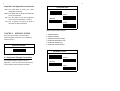
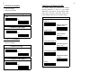
Configuration Commands
CONFIGURATION
MANUAL
START
ST LASER series
END
Bar Code Scanner
To
begin
procedures
the
configuration
To
finish
the
configuration
procedures
and
save
new
parameters in memory.
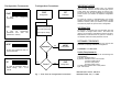
ABORT
To give up all parameters that you
have just selected.
SET
0
12345 67890
5
To make all parameters back to
default settings
with * in this
manual.
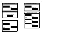
Configuration Commands
Configuration Procedures
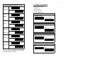
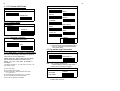
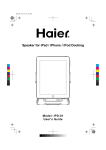
START
START
To
begin
procedures
SET
Configuration
the
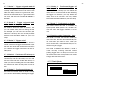
IMPORTANT NOTICE
All Defaults
configuration
END
To avoid any misuse or misunderstanding, we strongly
suggest and recommend that the configuration manual
should be used by either your dealer or your software
consultant for proper set-up and custom configuration.
Interface Type Settings
INFORMATION
Bar Code Type Settings
To
finish
the
configuration
procedures
and
save
new
parameters in memory.
Each standard package contains main unit, interface
cable and user's manual. The user's manual gives you an
overall review and information about the scanner only.
For those who can do the configuration by themselves,
please contact your dealer for separate configuration
manual.
All materials in this manual is for your information only and
are subject to change without notice. We reserve the
rights for any changes or upgrades that have to be done.
Reproduction of this manual or any part of its contents is
not allowed without the written permission of SCSC.
Other Options Setting
SOFTWARE COPYRIGHTS
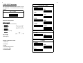
ABORT
Abandon ?
Yes
ABORT
Configuration
To give up all parameters that you
have just selected.
COPYRIGHT ©1996,SCSC.
Safety Requirements
No
SET
All parts of the softwares implemented in the scanners are
protected by Copyright International Regulations.
No
Finish ?
Yes
END
Configuration
To make all parameters back to
default settings
with * in this
manual.
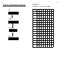
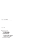
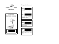
Fig. 1 - Flow Chart of Configuration Procedures
The scanner passes and complies with the following tests
and regulations.
A) Emission: EN55022 Class B
B) Emission: EN55022 Class B which includes
1) IEC801-2 (ESD) Class B
2) IEC801-3 (RS) Class A
3) IEC801-4 (EFT) Class B
C) CDRH class II and IEC class 2 laser product
D) UL, CSA and TUV
Manual P/No: SCCM - 80S-01A
Released Date: July 11, 2006
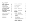
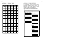
TABLE OF CONTENTS
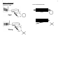
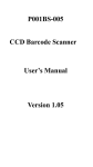
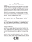
Aiming at barocde
1
CHAPTER 1
3
INTRODUCTION
1.1 Default Configuration
3
1.2 Custom Configuration
4
1.3 Configuration Procedures
4
CHAPTER 2
INTERFACE SETTING
5
2.2 RS-232C Parameters
9
BAR CODE SETTING
OPTIONAL SETTING
22
4.1 Reading Modes Parameters
22
4.2 Code Mark ( COde I.D.) Parameters
25
4.3 Pre-amble and Post-amble
26
4.4 Buzzer Parameters
27
4.5 Other Parameters
27
5
2.1 Keyboard Wedge Parameters
CHAPTER 3
CHAPTER 4
12
CHAPTER 5
USEFUL EXAMPLES
28
CHAPTER 6
USB Connection
29
APPENDICES
30
3.1 Code 39 Parameters
14
3.2 Interleave 2 of 5 Parameters (ITF2/5)
15
Appendix A ASCII CODE TABLE
30
3.3 Industrial 2 of 5 Parameters ( IND2/5)
16
Appendix B DECIMAL TABLE
31
3.4 Matrix 2 of 5 Parameters (MTX 2/5)
17
Appendix C OTHER OPTIONS
32
3.5 Codabar Parameters (NW-7)
18
3.6 EAN-13 Parameters
19
3.7 UPC-A Parameters
20
3.8 EAN-8 Parameters
21
3.9 UPC-E Parameters
21
A) Keyboard Wedge Parameters-Computer Type
32
B) Keyboard Wedge Parameters-Keyboard Layout
33
C) Readable Code
D) Code 11 Parameters
34
35
E) Code 93 Parameters
35
F) China Postage Parameters
35
G) General Parameters - Code Mark
36
H) General Parameters - Bar/Space Invert to Read
36
I ) K/B Control Code Emulation F1-F12
36
Appendix D
HEX-LABEL TABLE
37
1
2
Aiming at barcode
hold for an angle
Scan the Entire barcode
12345
12345
3
4
CHAPTER 1
INTRODUCTION
This manual provides all useful information regarding
configuration,
custom
configuration
and
configuration procedure. You are suggested to read
all information containing herein before starting to
configure your scanner. As stated, we recommend
that configuration, especially custom configuration,
better to be performed
by experienced users, your dealer or your software
consultant.
1.2 Custom Configuration
The scanner can be re-configured at any time for
your different application. You can change one or
several default parameters by scanning the labels
provided in this manual to fit our applications.
For
entering our own custom configuration, please refer
to Chapter 2,3,4 and appendixes of this manual for
details.
Please, however, note that once the
configuration
is
re-programmed,
the
desired
parameters will be saved in the memory even after
1.1. Default Configuration
The operation parameters of the scanner are set to
the power is turned off.
defaults at the factory in order to suit for the most
1.3 Configuration Procedure
popular bar code data collection applications.
One or more parameters of the scanner can be
reconfigured to meet your need. The basic steps of
All default parameters are marked with an asterisk "*"
customs configuration are as under :
in this manual. Generally, the defaults set in the
factory are:
1) Scan " START " label
* Emulation as keyboard wedge
2) Scan desired parameters
* IBM PC AT, PS/2 series computers
3) Scan " EXIT" label, otherwise proceed to the next
* US keyboard layout
* Data transmitted in lower case
step
4) Scan " END" label
* Reading mode: Trigger on/good read off
* Good reading beep active
In order to have a better idea about all configuration
* Keyboard data terminator : CR
procedures, please refer to the Fig. 1, Flow Chart of
* Keyboard number key: Alphanum
Configuration Procedure, which is on the overleaf of
* Red LED light on
the front cover of this manual.
6
5
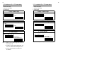
Important configuration commands:
START -Scan START label to initiate your custom
Computer Type
*PC/AT & PS-50,60,70,80
configuration procedure.
ABORT -Scan ABORT label to abadon all parameters
PC/XT
you have just selected.
END - Scan END label to finish the configuration
and save the new parameters in memory.
IBM5550
EXIT - "EXIT" is specially for ending the setup of
PS-55
"Hex-Label" printed in Appendix D.
Keyboard parameters include:
CHAPTER 2
INTERFACE SETTING
The scanner has 2 modes of communication,
keyboard wedge, and RS-232C, (CCD WAND and
OCIA are options.)
1. Keyboard layout
2. Keyboard speed
3. Keyboard character delay
4. keyboard upper/lower case
5. keyboard number keys
Keyboard Wedge
6. keyboard data terminator
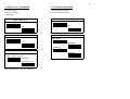
1. Keyboard Layout
* US
France
2.1 Keyboard Wedge Parameters
The keyboard wedge is convenient for most
applications. First of all, select one of the computer
type from labels below for keyboard interface.
Germany
Spain
7
8
5. Keyboard Number Keys
2. Keyboard Speed of PC/AT
* Normal
* Alphanum
Turbo
3. Keyboard Character Delay
Min. to Max:(00-99)
Define char. delay=??
Numeric Pad
6. Keyboard Data Terminator
* CR
None
Note: For setting up, please refer to the examples in
SPACE
Chapter 5.
TAB
4. Keyboard Upper/Lower Case
ESC
* Lower
Upper
Auto
Ctrl + C
9
10
2.2 RS-232C Parameters
The scanner also provides RS-232C interface to meet
your application . Scan the label below for RS-232C
1. Baud Rate ( bps)
19200
300
interface.
RS - 232C
600
1200
2400
RS-232 Pin Assignment:
4800
DUSB-9P Female
1
N/C (=no connection)
2
TXD
5
GND
7
CTS
8
RTS
9
VCC (+5V)
*9600
38400
2. Data Bits
* 8 Bits
DC Adapter
+5v +- 10%
150mA (min.)
7 Bits
3. Parity
RS-232C parameters include:
1. Baud rate
* None
2. Data bits
Odd
3. Parity
4. Handshaking protocol
5. Character delay
6. Data terminator
Even
11
12
4. Handshaking
* None
CHAPTER 3 BAR CODE SETTING
The scanner can read almost all popular symbologies
RTS/CTS
in the world.
Scan one or more codes from the
following labels to meet your applications.
Xon/Xoff
Readable Code Setting
*On
Code 39
Off
5. Character Delay
Min. to Max.:(00-99)
Define char. delay=??
On
ITF 2/5
6. Data Terminator
* Off
On
* CR
None
IND 2/5
* Off
LF
On
CR+LF
MTX 2/5
SPACE
TAB
*Off
*On
ESC
Ctrl + C
STX/ETX
Xon/Xoff
CODABAR
Off
13
14
Readable Code Setting ( Cont'd)
*On
3.1 CODE 39 Parameters
These parameters include:
1. Character set
EAN-13/UPC-A
Off
2. Verify check digit
3. Transmit check digit
4. Transmit start/stop digit
* On
1. Character Set
* Standard Code
EAN-8
Off
Full ASCII code
* On
UPC-E
2. Verify Check Digit
Off
* No
On
Yes
UPC/EAN
* Off
Add-on 2/5
3. Transmit Check Digit
*On
Code 128
* Yes
No
Off
On
Code 14
4. Transmit Start/Stop Digit
Off
* No
Yes
Standard readable codes include Code 93,
Code 11, Code IV, MSI/Plessy, China Postage
and ISBN/ISSN listed in page 25.
15
16
3.2 Interleave 2 of 5 Parameters
3.3. Industrial 2 of 5 Parameters
1. Verify check digit
1. Verify check digit
2. Transmit check digit
2. Transmit check digit
3. Code length
3. Code length
1. Verify Check Digit
1. Verify Check Digit
* No
* No
Yes
Yes
2. Transmit Check Digit
* No
Yes
3. Code Length
* Variable length
Min.=?? Max.=?? (4 - 48)
Fixed length
Custom define=???
Note: 1. Default is set to various length with minimum 4
and maximum 48.
2. In order to suit your routine application, you
may also re-define as fixed length up to 3.
3. You may see examples in Chapter 5 for
re-definition.
2. Transmit Check Digit
* No
Yes
3. Code Length
* Variable length
Min.=?? Max.=?? ( 2-24)
Fixed length
Custom define=???
Note: See examples in Chapter 5 for re-definition.
17
18
3.4 Matrix 2 of 5 Parameters
3.5 Codabar Parameters
1. Verify check digit
1. Transmit start/stop characters
2. Transmit check digit
2. Type of start/stop characters
3. Code length
1. Verify Check Digit
1. Transmit Start/Stop Characters
* No
* No
Yes
Yes
2. Transmit Check Digit
* No
2. Type of Start/Stop Characters
* abcd/abcd
Yes
ABCD/ABCD
ABCD/TN*E
3.Code Length
* Variable length
Min.= ?? Max.= ?? ( 2-40)
Fixed length
Custom define=???
Note: See examples in Chapter 5 for re-definition.
abcd/tn*e
19
20
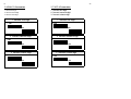
3.6 EAN-13 Parameters
3.7 UPC-A Parameters
1. Transmit first digit
2. Transmit second digit
3. Transmit check digit
1. Transmit first digit
2. Transmit second digit
3. Transmit check digit
1. Transmit First Digit
1. Transmit First Digit
* Yes
* Yes
No
2. Transmit Second Digit
No
2. Transmit Second Digit
* Yes
*Yes
No
3. Transmit Check Digit
* Yes
No
3. Transmit Check digit
* Yes
No
No
21
22
3.8 EAN-8 Parameters
1. Transmit first digit
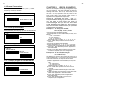
CHAPTER 4 OPTIONAL SETTING
This chapter provides you instructions for selecting
optional parameters in order to fit your special
2. Transmit check digit
requirements. These options include reading modes,
1. Transmit First Digit
* Yes
code mark, pre-amble, post-amble, buzzer pitch,
buzzer duration, power-up tone, and LED indicator.
Reading Mode Parameters
No
* Trigger on/good
read off
* Trigger on/good read
off delay=??sec.
2. Transmit Check Digit
* Yes
Trigger on/off
No
3.9 UPC-E Parameters
1. Transmit first digit
Continuous/LED
always on
Continuous/trigger off
2. Transmit check digit
Continuous/trigger off
delay=??sec.
1. Transmit First Digit
* Yes
No
Continuous/no trigger
Reading Mode Parameter
* Auto
2. Transmit Check Digit
* Yes
Testing
No
23
4.1.1 Mode 1 - Trigger on/good read off
24
Press thye trigger and LED ( of the reading
4.1.6 Mode 6 - Continuous/trigger off
But delay =??
window) will be turned on then scan a bar code
As above mode 5 except you can define the
label. The beep sounds for a good read, then,
delay time to control the LED off after releasing
LED turns off automatically. If a good read does
the trigger. For instance, you may define the
not occur, LED also turns off after THE DEFAULT 3
delay time as 05 seconds. You may untilize
SECOND.
Decimal & Hex-Label Tables for your own setup.
4.1.2 Mode 2 - Trigger on/good read
off But Define delay time=??
4.1.7 Mode 7 - Continuous/ no trigger
This mode is almost the same as mode 1, but
system power. When system is on, the LED is on
you can define delay time for turning off LED.
and vise versa. The trigger, therefore, is off no
For example, you can set to 07 seconds. (The
use.
This mode means the LED is controlled by
default is 3 second.) You can use the provided
Decimal and Hex-Lable Tables for your own
4.1.8 Reading mode Parameter - Auto
setup.
This mode is ST laser new function. While you
4.1.3 Mode 3 - Trigger on/off
This mode is a little bit different from above 2
modes, which is that trigger dominate the on/off
the Led. This means LED will be turned off when
don't use Laser, the laser will automatically turn
off, and when you need to use it, when you
focus on barcode, it will automaticaaly turn on,
without using any trigger.
you release the trigger and there will be no
This mode is idifferent from Mode 3, mode 3
delay time..
could non-stop scanning barcode without
pushing trigger and it is always on turn-on. But
4.1.4 Mode 4 - Continuous LED always on
this mode could save more power but on waste
This mode provides you to read bar code labels
enegry while user dosn't use it.
continuously with the LED always on. But note
that this mode will also enable LED always on
when you are not reading the bar code labels.
You will have to switch off the power to turn off
LED.
4.1.5 Mode 5 - Continuous/trigger off
This mode is much the same as mode 4 except
you can turn off the LED by releasing the trigger.
4.1.9 Flash Mode
Flash Mode
Enable
* Disable
26
25
4.1.10 Scanner Multi Read
Scanner Multi Read
Code Mark Parameters
Code 39
ITF 2/5
* single read
double read
IND 2/5
MTX 2/5
CODABAR
4.1.11 Buzzer Mode
Buzzer Mode
* Buzzer on
EAN-13/UPC-A
EAN-8
Buzzer off
UPC-E
Code 128
4.1.12 Vibrating Indicator
CANCEL
Vibrating Indicator
ON
*OFF
Note: 1. Read code type and then CANCEL label.
2. Please follow the rule for cancellation step by
step, i.e.: to read one code type and then
scan CANCEL label.
4.3 Pre-amble and Post-amble
4.2 Code Mark ( Code ID) Parameters
You may use the example listed below to define the
Pre-amble & Post-amble
Pre-amble=??
code mark for your own applications.
Please note that each code mark you define
has to follow the steps as example shown
below . You may also refer to Chapter 5
for details.
For example: to define " Z " as code mark for code 39. , the
steps will be as under :
a) Scan " Start " label.
b) Scan Code 39 label as below.
c) Refer to Appendix A. ASCII Code Table where shows
" 5" "A" stand for " Z".
d) From Appendix D. Hex-Label to scan " 5" "A" labels.
e) Scan " EXIT" label also from Hex-Label Table.
f) Scan " END" to complete your definition
Post-amble=??
Note: 1. You can define maximum 10
characters/digits for each pre-/post-amble.
2. Please refer to examples in Chapter 5.
Cancellation of Pre-amble & Post-amble
Pre-amble
CANCEL
Post-amble
Note: Read pre-amble for post-amble first and then
CANCEL label afterwards.
27
28
4.4 Buzzer Parameters
CHAPTER 5
Buzzer parameters include buzzer pitch ( buzzer
frequency) and buzzer duration.
Here we list examples concerning configuration steps
for your reference. We have illustrated the steps for
defining code mark. Now we try others and you will
see that it's very important and very useful of our
ASCII Code Table and Decimal Table shown in
Appendix A and Appendix B respectively.
Buzzer Pitch & Duration
Buzzer pitch=?? (0-22)
Buzzer duration=?? (0-127)
4.5 Other parameters
These parameters include power up tone and LED indicator.
* On
Power up Tone
Off
LED Indicator
* LED on
Good read off
LED off
Good read on
USEFUL EXAMPLES
Please do remember one thing , that is everytime before setting up your own definition,
you will have to write down the order of
characters/digits that you find out from ASCII
Code Table/Decimal Table first. This important
step will minimize mistakes when you proceed
configuration procedures.
Example 1. To setup pre-amble,
let's say AjX, of any code
Now simply follow the following steps:
1) From Appendix A. ASCII Code Table you may find
out that:
- " 4" & " 1" stand for A
- "6" & "A" stand for j
- " 5" & " 8 " stand for X
Please take note, in orders, "4", "1", "6", "A", "5", "8"
2) Scan " START" label printed in the front cover of
manual.
3) Scan the provided pre-amble label.
4) Follow the order of "4", "1", "6", "A", "5", "8" to scan
the bar code in the Appendix D. Hex-Label Table.
5) Then scan " EXIT" label also printed in Appendix D.
Hex-Label Table.
6) Finally, scan "END" label printed in the front cover
in order to complete your own configuration.
Example 2. To set variable length
for code ITF 2/5
The defaults of minimum and maximum length are 4
and 48 respectively. If you want to set 8 for minimum
and 20 for maximum, the steps will be as below:
4.6 Code(S) Single or Double Read
Code(S)
Single Read
Double Read
1) Refer to Appendix B. Decimal Table you may find
that :
- " 08 " stands for 8
- " 14 " stands for "20"
Please take note, in orders, "0", "8", "1", "4"
2) Scan " START" label printed in the front cover of
manual.
3) Scan the provided variable length of bar code
label.
4) Follow the orders you write down to scan bar code
labels from Appendix D. Hex-Label Table..
5) Scan " EXIT" label also printed in Appendix D.
Hex-Label Table.
6) Scan " END" label printed in front cover to
complete your configuration.
29
30
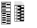
Chapter 6. USB Connection ( Optional)
Scan the following command codes to complete USB setting:
SET
START
USB Setting
END
APPENDICES
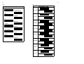
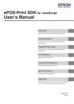
APPENDIX A. ASCII CODE TABLE
H
2
3
4
5
6
7
0
NUL DLE SP
0
@
P
`
p
1
SOH DC1
!
1
A
Q
a
q
2
STX
DC2 “
2
B
R
b
r
3
ETX
DC3
3
C
S
c
s
4
EOT DC4 $
4
D
T
d
t
5
ENQ NAK
%
5
E
U
e
u
6
ACK SYN
&
6
F
V
f
v
7
BEL
ETB
,
7
G
W
g
w
8
BS
CAN
(
8
H
X
h
x
9
HT
EM
)
9
I
Y
i
y
A
LF
SUB
*
:
J
Z
j
z
B
VT
ESC
+
;
K
【
k
C
FF
FS
,
<
L
\
l
D
CR GS
-
M
】
m
E
SO
RS
.
>
N
^
n
~
F
SI
US
/
?
O
_
o
DEL
L
0
1
#
=
{
|
}
31
32
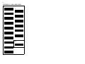
APPENDIX B. DECIMAL TABLE
H
APPENDIX C. OTHER OPTIONS
In this appendix, we also list some optional
parameters regarding computer
0
1
2
3
4
5
6
7
0
0
16
32
48
64
80
96
112
1
1
17
33
49
65
81
97
113
2
2
18
34
50
66
82
98
114
3
3
19
35
51
67
83
99
115
4
4
20
36
52
68
84 100
116
5
5
21
37
53
69
85 101
117
6
6
22
38
54
70
86 102
118
7
7
23
39
55
71
87 103
119
8
8
24
40
56
72
88 104
120
9
9
25
41
57
73
89 105
121
A
10
26
42
58
74
90 106
122
B
11
27
43
59
75
91 107
123
C
12
28
44
60
76
92 108
124
D
13
29
45
61
77
93 109
125
E
14
30
46
62
78
94 110
126
F
15
31
47
63
79
95 111
127
L
keyboard
types
layout of the keyboard
readable codes and parameters for
these readable codes, general parameters.
A)
Computer Type
IBM 3196/97,3476/77
NEC N5200
NEC PC-98
ACER 7300
Sun Type 4/5/5C
ADI CC-III
MAC SE
LC-6533
IBM 4714
and
wedge,
33
34
B)
C)
Readable Code
Keyboard Layout
On
Switzerland
Sweden/Finland
Code 93
* Off
Italy
On
Belgium
Code 11
* Off
U.K.
On
Denmark
MSI/Plessy
* Off
Portugal
On
Norway
China Postage
Latin America
On
Japan
Poland
* Off
Code IV
Holland
* Off
On
ISBN/ISSN
*Off
* Off
GTIN14
ON
* Off
Ean-128
ON
35
36
D) Code 11 Parameters :
1. Number of Check Digit
Yes
3. Transmit Check Digit
One
No
Two
G) General Parameters- Code Mark
2. Transmit Check Digit
Yes
Code Mark Parameters
Code 93
Code 11
No
MSI/Plessy
China Postage
E)Code 93 Parameters
Concatenation
On
Code IV
Off
F) China Postage Parameters
1. Code Length
Variable Length
Min=? Max=?(2-40)
CANCEL
Note: 1. Read code type ( just once a time) and then
CANCEL label afterwards.
H) General Parameters
Bar
Space Invert to Read
Yes
Fixed length
Custom Define=???
2. Verify Check Digit
Yes
No
I) K/B Control Code Emulation F1-F12
K/B Control Code Emulation F1-F12
Disable
No
Enable
37
APPENDIX D. HEX-LABEL TABLE
0
A
1
B
2
C
3
D
4
E
5
F
6
7
EXIT
8
9