1
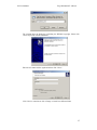
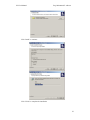
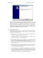
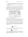
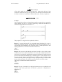
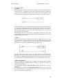
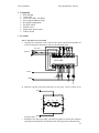
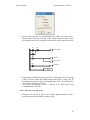
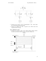
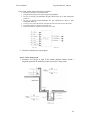
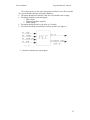
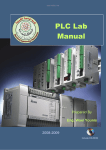
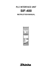
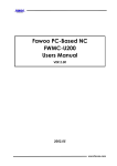
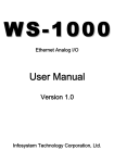
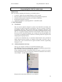
PLC Lab Manual
Eng. Mohammed F. Alkrunz
Experiment #3
Programming the PLC Via Ladder logic
OBJECTIVES
After successfully completing this laboratory, you should be able to:
to convert a simple electrical ladder diagram to a PLC program.
Know the difference between physical components and program components.
sketch the ladder programs using the tools available in WPLSoft.
Download the program to the PLC.
operate the program, via placing the PLC in the RUN mode .
1. Basic Information
1.1.
Introduction
PLCs are special computers designed to operate in the industrial environment with
wide ranges of ambient temperature and humidity. They have a number of different
programming languages which include Ladder logic, Mnemonic instructions, and
Sequential Function Charts. Ladder logic is the main programming method used for
PLCs. It is a graphical language which has been developed to mimic relay logic. The
decision to use the relay logic diagrams was a strategic one. By selecting ladder logic
as the main programming method, the amount of retraining needed for engineers and
tradespeople was greatly reduced.
a software tool called Wpl runs on a personal computer allows users to sketch the
ladder diagram and then transfers its compiled code serially to the PLC. Such a
software tool is more convenient and it supports mnemonic and SFC programming
languages as well.
1.2.
WPLSoft Installation and setup
Start-up your computer to Windows 95/98/2000/NT/ME/XP system.
Insert WPLSoft CD into the CD-ROM disk or download installation program from
http://www.delta.com.tw/product/em/plc/plc_main.asp
(If the installation program is downloaded from the website, it needs to be saved in
the designated directory after uncompressing, and then the installation can be started.)
Click “START”, and then click on “RUN”
Designate the location where WPLSoft is to be installed
14
PLC Lab Manual
Eng. Mohammed F. Alkrunz
The program show the dialog box explaining the WPLSoft copyright. Please click
"Next" to proceed with the installation.
Enter the user name and the organization then click “Next>” .
Click "Next" to comtinue or click "Change“ to install to a different folder.
15
PLC Lab Manual
Eng. Mohammed F. Alkrunz
Click “Install” to continue.
Click “Finish” to complete the installation.
16
PLC Lab Manual
Eng. Mohammed F. Alkrunz
DELTA’s PLC DVP Series has main processing units and extension units. The main
processing units offer 14-60 points and the extension units offer 8-32 points. The
maximum input/output can be extended up to 128 points. It also can be used on
applications according to INPUT/OUTPUT points, power sources, output modules,
digital/analog exchanges (A/D & D/A converter). In addition, DVP SS Series has the
special modules (AD/DA/PT/TC/XA) used for extending its functions and the
maximum special modules can be extended up to 8 units.
1.3.
Delta PLC memory map
In the previous section we introduced two types of memory variables in Delta PLCs;
the input relays and the output relays. In Delta PLCs there are total of 8 memory
location types as described below.
Input Relays: Single bit variables and can be extended to 128 points. They are
indicated with X sequence in Octal numbering mode.
Output Relays: Single bit variables and can be extended to 128 points. They are
indicated with Y sequence in Octal numbering mode.
Internal Auxiliary Relays: Single bit variables. They are indicated with M
sequence in Decimal numbering mode ranging from M0 to M1279. M1000 and
above are used for system flags and special purpose auxiliary relays.
Steps: Single bit variables indicated by S sequence in Decimal numbering mode
ranging from S0 to S127.
Timers: Indicated by T sequence in Decimal numbering mode ranging from T0 to
T127. Each timer has a 16-bit holding register for its preset value as well as a
single bit variable representing its contact.
Counters: Indicated by C sequence in Decimal numbering system. Similar to
Timers, each counter has a holding register and a single bit contact. There are 128
16-bit counters ranging from C0 to C127 and there are 13 32-bit counters
indicated as C235 to C238, C241, C242, C244, C246, C247, C249, C251, C252,
and C254. These later counters are referred as high speed counters.
17
PLC Lab Manual
Eng. Mohammed F. Alkrunz
Data Registers: 16-bit variables indicated by D sequence in Decimal numbering
mode ranging from D0 to D599 and from D1000 to D1143. D1000 and above are
special purpose registers.
Index Registers: Two pointers indicated by E and F. They are D1028 and D1029
respectively.
These memory locations are reached easily using their names. However one may
reach them by means of the PLC device addresses specified by Delta. This method is
useful when these memory locations are monitored or preset at run time by an
external devise such as a personal computer. The device addresses table of Delta
PLCs is illustrated in Table 2.1. It is not a traditional memory map where each
location is byte width. However, the location size depends on the variable type.
Table 2.1: Device address table of Delta PLCs.
1.4.
Ladder logic and mnemonic programming
The instructions from a ladder diagram, mnemonic, or SFC are translated to machine
code that can be stored in the PLC memory. Each horizontal rung on the ladder in a
ladder program represents a line in the program and the entire ladder gives complete
program in “ladder language”. There are three basic symbols used in ladder logic.
The first one is NO - NC contacts : NO contact is an instruction that tells the
processor to look at a specific bit in its RAM memory. If the bit is 1, the instruction is
true. and if it is 0, the instruction is false. The determining factor in choosing which
bits in its memory to look at is the address. It could be some auxiliary bit (M), a timer
contact (T), a counter contact (C), a state bit (S), or it might be connected to an
external input (X).
X0
Normally Open Contact
NC contact plays the same role as the previous one, except that if the bit addressed is
1, the instruction is false and if it is 0, the instruction is true.
X0
Normally Closed Contact
The second symbol is output: for outputting to the output module. If the
instructions to the left on its rung have a true path to the leftmost vertical rail, then the
PLC will set the bit to which it is referenced via the address to 1. If no complete true
path is available, it will set the bit to 0.
18
PLC Lab Manual
Eng. Mohammed F. Alkrunz
Y0
Device Output
The third symbol is special instruction boxes: Along with the basic logic
instructions addressed in the previous part, PLCs are microprocessor-based and they
facilitate a wide area of useful built in functions like timers, counters, comparators .
CNT
C0
K10 Counter
Example
Let us assume that we have two inputs buttons and three output devices connected to
a PLC terminals X1, X2, Y1, Y2, and Y3 respectively. Assume also that the PLC is
loaded with the program shown in Figure 2.5.
The program has 3 rungs which are explained as follows:
Rung 1: If we push on button X1, its associated internal bit labeled X1 is logic 1
(true). Thus, when the processor executes this rung via the input instruction -] [-, it
sees the rung’s input condition as true. Therefore it puts a 1 in the output bit Y1. This
ladder program line is converted to mnemonic instruction as
LD X1
OUT Y1
Rung 2: The processor works through the inputs from left to right, and the output
instruction sees a true condition only when it sees a true path via input instructions to
the left rail. If you push both push buttons connected to terminals X1 and X2, then the
processor sees their associated bits logic 1 and hence puts a 1 in the output bit Y2. If
none or one push button is pushed, the input conditions to the left of the output
instruction do not produce a true path. This type of program rung is called an AND
because both push buttons, X1 AND X2, must be pushed to activate the output.
This rung is converted to mnemonic instruction as
LD X1
AND X2
OUT Y2
Rung 3: This type of instruction is an OR gate because there are two pathes that will
turn the output: either push button X1 OR X2 is pushed. It is implemented in
mnemonics as
LD X1
OR X2
OUT Y3
19
PLC Lab Manual
1.5.
Eng. Mohammed F. Alkrunz
Functions on PLCs
Counters
When the operation result of instructions preceding the CNT instruction has changed
from OFF to ON, 1 is added to the count value. When the counter has counted out
(count value = set value), the state of the counter contacts are toggled. In the
following example the output Y0 is activated after entering 5 clock pulses at input
When the operation result of the instructions preceding the CNT instruction remain
on, counting is not performed. After the counter has counted out, the count value and
the status of the contact will not change until the RST instruction is executed. A
negative number cannot be used as a set value. When the set value is 0, the same
processing as for 1 is performed.
The instruction CNT uses 16-bit registers to accumulate counted values in the valid
counters domain (C0 to C127). On the other hand, the instruction DCNT uses 32-bit
registers for high speed counters.
Timers
When the operation result of instructions preceding the TMR instruction are on, the
coil of timer turns on and counts up to the set value. When the timer times out
(counted value >= set value), the timer contacts are toggled. In the following example
the output Y0 is activated 3 seconds after activating the input X0.
Delta PLCs support 128 timers (T0 to T127). The timer will be reset when the
operation result of instructions preceding the TMR instruction change from ON to
OFF. Moreover, The RST instruction may be used to reset the timer values. Timers
use 16-bit registers and a negative number (-32768 to -1) cannot be set as a set value.
Other useful functions
In the User manual you will find plenty of functions that facilitate data movement,
arithmetic, comparison, and other operations similar to instructions provided for
traditional microprocessors.
For example, the instruction MOV K14 D0 moves the decimal value 14 to data
register D0.
Another example, the instruction CMP D7 K23 M0 compares the value of D7 with
the decimal number 23. If larger M0 will be set, else if equal M1 will be set,
otherwise if smaller then M2 will be set.
20
PLC Lab Manual
Eng. Mohammed F. Alkrunz
2. Equipments
DVP14ES00R
1x10A mcb.
230V(coil), 50Hz, 10A Relay
Green and red indicator lamp.
NO and NC pushbuttons.
ON-OFF switch.
Flexible wires.
Single phase power source.
Control board.
3. Procedure
220V/50Hz
SW3
SW2
SW1
mcb 1x10A
PB2
PB1
Part 1 : DC motor set-reset circuit
1. Assemble the components of the control circuit on the control board and make the
required wiring and connections as shown in the following figure
N
L
S/S
L
X4
X5 X6 X7
X0 X1
X2 X3
N
DVP-14ES
+24V
Y0
24G
Y1
Y2
Y3
Y4
C0
C1 C2
C3 Y5
+24VDC
R1
220V/50Hz
COIL
R2
220V/50Hz
COIL
220V/50Hz
220V/50Hz
GREEN
RED
24GND
2. Make the required wiring and connections for the power circuit as shown in the
+24V
R2
R1
Left
D1
D2
LSL
LSR
M
R2
following figure
3.
R1
GND
Starting a new project in Wpl, you will be prompt to specify the memory
capacity of the target PLC model and a title for the project as shown below.
21
PLC Lab Manual
Eng. Mohammed F. Alkrunz
4. Specify 4000 steps for the DVP14ES00R PLC model and write down a
suitable project title then click OK. In the Ladder diagram window sketch
the program shown below using the tools available in the common tools bar.
X4
X5
M0
Internal Relay
Y0
R1 Relay
Y5
Green Lamp
Y3
Red Lamp
M0
M0
M0
END
5. Wpl assumes by default that the target PLC is connected to the PC through
COM1. You may change this default sitting from Option / Comm. port. To
download your program, click on Communication > PLC . Select Write PLC
from the drop menu and click OK.
6. To operate the program, the PLC is placed in the RUN mode from
Communication / PLC Run.
Part 2 : DC motor reversing circuit
1. Starting a new project in Wpl. In the Ladder diagram window sketch a
program represents the following control circuit .
22
PLC Lab Manual
Eng. Mohammed F. Alkrunz
2. Download your program, click on Communication > PLC . Select Write
PLC from the drop menu and click OK.
3. Operate the program, the PLC is placed in the RUN mode from
Communication / PLC Run.
Part 3 : Sliding Gate system
1. Starting a new project in Wpl. In the Ladder diagram window sketch a
program represents the following control system for a sliding gate
23
PLC Lab Manual
Eng. Mohammed F. Alkrunz
The program should satisfy the following conditions :
The motor should be overload protected.
The gate should stop in case of pressing stop-pushbutton.
In case of pressing Up-pushbutton the gate should move up to max limit(limit
switch 2) .
In case of pressing Down-pushbutton the gate should move down to max
limit(limit switch 1) .
In case any one passed the photocell interrupts the down state and activates the up state.
The flusher lamp to be operated in the down state.
Required mechanical and electrical interlocks to be used.
2. Download and operate your program .
Part 4 : Water Pump system
1. Starting a new project in Wpl. In the Ladder diagram window sketch a
program represents the following control system for a water pump
24
PLC Lab Manual
Eng. Mohammed F. Alkrunz
The system consists of one water pump and controlled via two float switches.
The system should satisfy the following conditions :
The pump should run if and only if the well is full and the tank is empty.
The pumps should be protected against :
o Phase failure.
o Changing the phase sequence.
o Under voltage.
The pump should run after a time delay of 5 seconds.
The system should be controlled by two float switches (see figure 1).
2. Download and operate your program
25