1
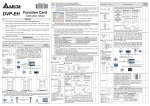
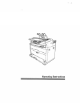
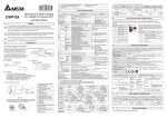
3
INSTALLATION & WIRING
1. Direct mounting to the expansion slot in the MPU of 2.
the EP/EH series
5
Connecting to DVP
series PLC via accessory
cable
DVPDU-01 Digital Setup Display
Instruction Sheet
1
Please power down the MPU of the
Please power down the PLC MPU prior to install the DU-01,
PLC prior to install the DU-01, which
which is connected via a high-density connector. Also please
is
refer to the figures above for proper operation.
connector.
via
a
high-density
Also please read the
in arrow direction.
correctly to prevent damage.
damage.
DU-01 Digital Setup Display has two operation modes, TS-01 and
TC-01.
The mode selection switch locates at the back of the
DU-01.
Factory setting is TS-01 mode.
TS-01 OPERATION
1.
Switch DU-01 to TS-01 mode. (Please see the back of the DU-01)
2.
Main Process
c) Password key clear (KEY CLR): Same as the operation above. Open WPLSoft, select [TC-01
TC-01
3. Clear P, D, F of TC-01: select the device (P, D or F) to be cleared, press
then press ESC.
Operation Mode
ESC
Auto Save
OK
Press and hold for 3 sec.
ESC
No Save
YY-MM-DD
2.
password key clear], and operate as instructed.
Press and hold for 3 sec.
ESC
HH-MM-SS
OK
+
P,D,F selection
Confirm & update time
Confirm
Device
Device
Selection
Device Selection
X, Y, M, S
T, C, D
P(Program)
CR
OK
ESC
1
2
3
4
5
6
7
8
9
ESC
OK
DU-01
3
R: read (RD) indication (TC-01)
4
“In communication” indication
5
6
7
ER: Error message display
9
Display Area
Number Selection
Press and hold for 3 sec.
OK
OK
Bit
Device
OK
Force On/Off setting
Monitor status of 8 consecutive
devices from the specified number
Device confirm
ESC
ESC
Press
D: Data Register indication
(TC-01)
F: File Register indication
(TC-01)
CR: Control Register indication
(Extension Module)
8
Number Selection
Press and hold for 3 sec.
Specified No.
Display
Device confirm
ESC
to complete entering & return
OK
OK
OK
OK
Word
Device
Enter a number
Reading P (Program).
You can press ESC to
pause reading.
Setting reading range.
(default start & end
addresses are latched
area range. User can
re-set it.)
3.
Start-up display mode setting (press
+
Any mode*
Finish reading.
Monitor
Mode
Time & device
content
Press
Until
+
+
shows
14 Bit devices X, Y, M, S indication
Enter start address
2746 is the CHKSUM
of writing data
Finish reading
Enter end address
Reading processing...
You can press ESC to
pause reading.
Sleep mode
16 Back to previous status
17 Enter number or select device
*Note: not include system operation mode setting
18 Confirm
4.
You can press ESC to
pause reading.
buttons simultaneously)
Sleep mode activated if no button is pressed
within 30 seconds
15 Digit backspace / Run (TC-01)
Reading F (file register)
Enter Set Value
ESC
ESC
d1EC is the CHKSUM
of writing program
10 Enter button
indication
K (Decimal), H (Hexadecimal)
11
indication
Contacts & coils of timer /
12
counter indications
Word devices T, C, D, DD (32-bit)
13
indication
19 Enter number or select device
F (File Register)
Specify a number
Device
Monitor
P: program area indication
(TC-01)
W: write (WR) indication (TC-01)
D (Data Register)
DD(32-bit)
Overview of the Product - Names of Parts
2
simultaneously,
RD read mode
ESC
In TC-01 mode, DU-01 (specified as TC-01 hereof) has the following functions for DVP all series:
• Read/write the program P, data register D and file register F from PLC.
• Copy program and data.
• Support the PLC password protection.
1
+
4. RD mode description:
Display
Selection
In TS-01 mode, DU-01 (specified as TS-01 hereof) has the following functions:
• Read/Write both the internal devices of PLC (e.g. perpetual calendar, bit devices (X, Y, M, S)
and word devices (T, C, D)) and the Control Register (CR) inside the extension units.
• Support the read/write 32-bit data register.
• Set Start-up display and power save mode.
• Monitor the devices.
• If connect the accessory cable to ES-series without perpetual calendar, the Time Display will
start from 00-00-00 calculated by the microprocessor of DU-01 (timing error may occur).
• Give RUN-STOP command to PLC.
It also writes the password to the PLC for
added protection.
Time Mode
The current operation
Open WPLSoft [Setting] [TC-01 password key setting].
Select [Enter TC-01 password key], and operate as instructed.
After setting, display shows the figure on the right. (KEY SET),
then press ESC to exit.
b) TC-01 has password key setting, therefore, only if the PLC has no password protection or with the
same password with TC-01 can process the writing.
Back of the DU-01
1.
Indication of internal data storage model
In RD or WR mode, press ESC button and hold for 3 seconds or
more to enter password setting. See the figure on the right:
(No need to shut down the MPU)
mode will be displayed every time when power up.
TS-01
Indication of the connected MPU model
a) Password Key Setting
Put the
DO NOT push it down vertically to prevent
4
INTRODUCTION
TC-01
Password key setting of TC-01 can be set via WPLSoft. The purpose is to read/write to the key-locked
PLC as long as the password setting matches with the one in PLC. To unlock the password key
setting, please use WPLSoft as well.
face-up DU-01 slantly in the extension slot, then push it down
figures on the right for operation
2
1. Switch the DU-01 to TC-01
mode (please see the back of
the DU-01), and select RD (to
read P, D and F in the MPU of
PLC) or WR (to write the data
in P, D, F of DU-01 to the MPU
of PLC).
Note: P: Program, D: Data register, F: File register
2. TC-01 Password Key Setting
WARNING
connected
TC-01 OPERATION
Please see the back page for detail information about the process of each mode.
Finish reading
Finish reading
WR mode description:
4.
Various process for operation modes under TS-01 mode
WR writing mode
(On: activate, Off: deactivate)
Sleep mode setting
Fill 0 setting (fill 0 before number or not) (On: not to display 0, Off: display 0)
Start-up display setting (On: allow to customize start-up display,
Off: Default time display)
+
System operation
mode setting
P,D,F selection
Device Confirm
R
P
W
D
CR
F
Auto Save setting
ER
Time display mode
K
H
X
Y
M S
C D DD
T
+
ESC
P (Program)
D (Data Register)
OK
F (File Register)
Select yy-mm-dd/hh-mm-ss
PLC calendar setting
R
P
W
D
CR
F
On/Off
Mode selection
ER
Confirm & update the time
Time display mode
OK
Blink alternatively
Writing to P (Program)
in PLC.
You can press ESC
to pause writing during
TC-01-> PLC.
K H
X
Y
M
S
C D DD
T
+
ESC
OK
Field selection
for setting
Set the contents
Start + End
Setting reading range.
(default start & end
addresses is latched
area range. User can
change it.)
Finish writing.
d1EC is the CHKSUM
of writing data.
Finish writing
d1EC is the CHKSUM
of writing data.
ESC
The right four digits show 8 consecutive
displays/settings that starts from Y10
Writing to F
(File Register) in PLC.
You can press ESC
to pause writing during
TC-01->PLC.
The left four digits show device 's number
W
W
P
D
F
CR
ER
Select device
X, Y, M, S
Device status display
Move to the
digit to be set
OK
Move the bit to
desired device's
number
Set device's number
Forced On/Off
setting
ESC
Use
P
D
F
CR
ER
DD stands for 32-bit data register
P
D
F
CR
K
Both timer and counter have coils & contacts monitor.
OK
DIMENSIONS & ACCESSORY
OK
K
Move to the
digit to be set
Confirm device
Select device
Word device
T, C, D, DD
to switch between K (decimal) / H (hexadecimal) display mode.
For 32-bit registers, use
to move to display the two left-most digits.
At this time, indicator
will light up.
ER
K
Set the number
Current value
display
ESC
For example:
Display two left-most digits
for 32-bit register.
OK
W
D
P
F
CR
Enter Set Value & return
to monitor mode
ER
Move to the digit
to be set
Expansion
COM Port
(Press and hold for 3 sec.)
Current value
display
Error-04 F-read error. ES series does not have file registers.
Error-05 F-write error. The source model unmatched the destination model.
Error-06 PLC is running. Writing to P is not permitted.
Enter Set Value mode
ESC
Device number setting
W
P
D
F
CR
ER
T, C, D, DD
ESC
W
P
D
CR
F
ER
Expansion unit number (0,1,2...7)
K
(Press and hold for 3 sec.)
OK
Specify CR number
K
ERROR CODE TABLE
Code Explanation & Troubleshooting
P-read error. PLC is password-locked while the TC01 has wrong or no password
key. Need unlock the password setting on PLC or set password in TC-01 via WPL.
P-write error. PLC is password-locked while the TC01 has wrong or no password
key; or the source model unmatched the destination model.
D-read error. Illegitimate read range (read range only available for the general data
registers of each models, not include special D)
D-write error. The source model unmatched the destination model.
OK
K
Enter Set Value
CR number
The accessory cable connects the DU-01 (the extension COM port of figure above) and
DVP-series PLC COM1 (RS-232) port. Therefore, the DU-01 can be connected to ES/SS/EX
or SA/SX models via the cable, as well as direct installation in the extension slot of EP/EH
models.
OK
(Press and hold for 3 sec.)
ESC
K
Error-03
ER
ESC
OK
Error-02
CR
OK
confirm device
W
DU-01
Error-01
F
Y10,Y12,Y15,Y17 are On
(Depends on actual output of the PLC)
Press and hold for 3 sec.until the blinking cursor shows
ESC
Error-00
D
Finish writing
Connecting to
DVP-PLC COM1
(RS-232 Port)
Code
P
Y10 Y11 Y12 Y13
K
OK
W
7
W
ER
K
Device select mode
ESC
CR
K
Finish writing
6
F
Y14 Y15 Y16 Y17
Finish writing.
Finish writing
D
K
Device select mode
d1EC is the CHKSUM
of writing data.
P
select device
Specify the expansion
unit number
OK
Current value
display
confirm CR
32-bit
ESC
ESC
Device select mode
R
W
P
D
CR
F
ER
Device select mode
K
H
X
ESC
Y
M
S
T
C
D DD
+
OK
PLC status display
PLC status switch
Time display mode
16-bit
OK
Enter Set Value mode