1
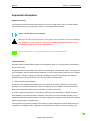
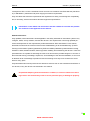
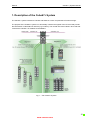
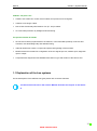
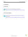
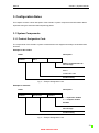
Manual Cube67+ System Description of Cube67+ System Installation Configuration Notes www.comoso.com Manual Cube67+ | System Manual Publisher's Note Cube67+ System Manual Version 1.4 Edition 08_12 EN Article No. 56974 Murrelektronik GmbH Falkenstraße 3 D-71570 Oppenweiler Phone +49 (0) 7191 47-0 Fax +49 (0) 7191 47-130 [email protected] 2 www.comoso.com Manual Cube67+ | System Manual Service and Support Website: www.murrelektronik.com In addition, our Customer Service Center (CSC) will be glad to assist you: Our Customer Service Center can support you throughout your project in the planning and conception of customer applications, configuration, installation, and startup. We also offer competent consulting or - in more complex cases - we even provide direct onsite support. The Customer Service Center provides support tools. It performs measurements for fieldbus systems, such as PROFIBUS DP, DeviceNet, CANopen, and AS interface, as well as energy, heat, and EMC measurements. Our coworkers at the Customer Service Center provide their competence, know-how, and years of experience. They are knowledgeable about hardware and software, and compatibility with products made by various manufacturers. You can contact the Customer Service Center at telephone number +49 (0) 71 91 47-424 or by email at [email protected]. 3 www.comoso.com Manual Cube67+ | System Manual About the User Manual and its Structure 4 www.comoso.com Manual Cube67+ | System Manual Here are links to the bus unser manuals: >>> PROFIBUS (www.profibus.com) 5 www.comoso.com Manual Cube67+ | System Manual Table of Contents Publisher's Note ...................................................................................................................................... 2 Service and Support ................................................................................................................................ 3 About the User Manual and its Structure ................................................................................................ 4 Table of Contents .................................................................................................................................... 6 Important Information .............................................................................................................................. 8 1. Description of the Cube67+ System .................................................................................................. 10 1.1 Explanation of the bus systems ................................................................................................... 11 2. Installation ......................................................................................................................................... 12 2.1 Mounting ...................................................................................................................................... 12 2.2 Connection Diagram .................................................................................................................... 12 3. Configuration Notes ........................................................................................................................... 13 3.1 System Components ................................................................................................................... 13 3.1.1 Product Designation Code .................................................................................................... 13 3.1.2 Cube67+ Bus Node ............................................................................................................... 14 3.1.3 Cube67 modules ................................................................................................................... 15 3.1.4 Cube67+modules .................................................................................................................. 15 3.1.5 Internal system connection – hybrid line ............................................................................... 16 3.1.6 7/8“ Power cables Pre-wired ................................................................................................. 17 3.1.7 Accessories ........................................................................................................................... 18 3.2 Internal system connection .......................................................................................................... 21 3.2.1 Topology................................................................................................................................ 22 3.2.2 Internal System Connection Terminations ............................................................................ 23 3.2.3 Segments and lines ............................................................................................................... 24 3.2.4 Maximum expansion ............................................................................................................. 24 3.2.5 Number of components ......................................................................................................... 24 3.2.6 Load rating ............................................................................................................................ 26 3.2.7 External supply of the actuator supply .................................................................................. 27 3.3 Power Supply ............................................................................................................................... 28 6 www.comoso.com Manual Cube67+ | System Manual 3.3.1 Configuration Notes .............................................................................................................. 28 3.3.2 Recommended power supply units ....................................................................................... 29 3.4 Connecting Sensors and Actuators ............................................................................................. 30 3.4.1 Sensor supply ....................................................................................................................... 30 3.4.2 Supply of external components (art. no. 56 710 / 56 720) .................................................... 31 3.4.3 Analog setting modules ......................................................................................................... 31 3.4.4 Actuators ............................................................................................................................... 32 3.4.5 Diagnostic input DESINA ...................................................................................................... 33 3.5 Electromagnetic Compatibility (EMC) .......................................................................................... 35 Glossary ................................................................................................................................................ 39 Legal Provisions .................................................................................................................................... 42 7 www.comoso.com Manual Cube67+ | System Manual Important Information Symbols and Icons This manual contains information and instructions you must comply with in order to maintain safety and avoid personal injury or damage to property. They are identified as follows: Notes indicate important information. Warnings contain information that, if you ignore this information, may cause damage to equipment or other assets or, if you fail to comply with safety precautions, may constitute a danger to the user's health and life. These instructions are recommendations issued by Murrelektronik. Intended Purpose Read this manual carefully before startup of the equipment. Keep it in a location that is accessible to all users at all times. The products that are described in this manual were developed, manufactured, tested, and documented in compliance with the relevant safety standards. In normal cases, these products do not constitute any danger to persons or objects, provided the handling specifications and safety instructions described in this manual are observed. They meet the following requirements: • EMC directive (2004/108/EEC) The products are designed for industrial use. An industrial environment is defined as one in which loads are not connected directly to the public low-voltage power grid. Additional measures must be taken if the products are used in private, business, or trade environments. The safe, troublefree functioning of the products requires proper transportation, storage, mounting, and installation, and careful operation. Operation of the devices for their intended purposes is only guaranteed when the enclosures are fully mounted. If aggressive media are used, check their material resistance depending on the application. Current safety and accident prevention laws valid for a specific application must be observed for the configuration, installation, setup, maintenance, and testing of the devices. The power supply must 8 www.comoso.com Manual Cube67+ | System Manual correspond to SELV or PELV standards. Power sources in accordance with EN 61558-2-6 (transformer) or EN 60950-1 (switched-mode power supply) meet these requirements. Only use cables that meet the requirements and regulations for safety, electromagnetic compatibility, and, if necessary, telecommunications terminal equipment specifications. Information on the cables and accessories that are suitable for use with this product are contained in the Appendix to this manual. Qualified Personnel Only qualified, trained electricians knowledgeable in the safety standards of automation systems may configure, install, set up, maintain, and test the devices. The requirements concerning qualified personnel are dependent on the requirements profiles described in ZVEI and VDMA. For this reason, electricians must know the contents of the manual "Weiterbildung in der Automatisierung" (Further Training in Automation Systems) published by ZVEI and VDMA published by Maschinenbau-Verlag, Post Box 710864, 60498 Frankfurt, Germany) before installing and maintaining the devices. These are specialists who are capable of assessing the work to be done and the possible dangers on account of their technical training, knowledge, experience, and knowledge of the relevant standards; or who have an identical level of knowledge equivalent to technical training since they have worked in the same area for many years. Only Murrelektronik technical personnel are allowed to execute work on the hardware and software of our devices, if they are devices not described in this manual. Unqualified tampering with the hardware or software, or failure to observe the warnings cited in this manual may result in severe personal injury or damage to property. 9 www.comoso.com Manual Cube67+ | System Manual 1. Description of the Cube67+ System The Cube67+ system is based on Cube67 and features a more comprehensive functional range. The purpose of the Cube67+ system is to decentrally combine the signals of the I/O level and provide this information via the field bus network (e.g. Profibus). The central unit is the Cube67+ bus node that connects the Cube67+ I/O modules to the fieldbus. Fig. 1: The Cube67+ System 10 www.comoso.com Manual Cube67+ | System Manual Cube67+: the plus is for... • Cube67+ bus nodes can control more modules, thus process more I/O signals. • It allows to use longer cables. • New IO link functionality with Cube67+ IOL (IO - link) modules. • An even better protection by intelligent load monitoring. The proven benefits of Cube67 • the I/O level is directly implemented in the machine, in the immediate proximity of sensors and actuators, thus eliminating bulky and awkward wiring, • reduced dimensions ensure a compact and space-saving design of the machine. • Multifunctional I/Os enable free configuration of the two signals per slot, whether input, diagnostic input or output. • Comprehensive diagnostics with detailed information on type and location of the fault or error 1.1 Explanation of the bus systems For the descriptions of the different bus types please refer to the bus manuals. You will find an overview in the section "Manual Overview and Layout" in this manual. 11 www.comoso.com Manual Cube67+ | System Manual 2. Installation 2.1 Mounting Please refer to the Technical Data Manual for the mounting rules. You will find an overview in the section "Manual Overview and Layout" in this manual. 2.2 Connection Diagram For the exact connection diagram and settings please refer to the corresponding product manuals. You will find an overview in the section "Manual Overview and Layout" in this manual. 12 www.comoso.com Manual Cube67+ | System Manual 3. Configuration Notes This chapter contains a short description of the Cube67+ system components and information that is important during the electromechanical planning phase. 3.1 System Components 3.1.1 Product Designation Code The components of the Cube67+ system are described in two diagrams that help to understand their functions Example for bus nodes: Name CUBE67+ Description BN-P Module characteristics of the I/O range Function BN-P = Profibus DP node Product family Fig. 2: Example Designation Code Example for modules: Name CUBE67+ Description DIO12 IOL4 E 8xM12 E = expansion module C = compact module Sockets Module characteristics of the I/O range Product family Fig. 3: Example Designation Code 13 www.comoso.com Manual Cube67+ | System Manual 3.1.2 Cube67+ Bus Node The bus node connects the I/O modules to the fieldbus. It is supplied via a 7/8" power cable and features four connections for the internal system connection. A maximum of 10 I/O modules per segment can be connected. This is a total of up to 20 I/O modules for one bus node. The I/O modules are supplied via the internal system connection. Article number Description 56521 Cube67+ BN-P Tab. 1: Cube67+ Bus Node For the exact connection diagram and settings please refer to the corresponding product manuals. You will find an overview on the manuals in the section "Manual Overview and Layout" in this manual. 14 www.comoso.com Manual Cube67+ | System Manual 3.1.3 Cube67 modules All Cube67 modules can be operated at the Cube67+ bus node, You will find an overview on the different Cube67 modules in the Cube67 System Manual. You will find an overview on the manuals in the section "Manual Overview and Layout" in this manual. 3.1.4 Cube67+modules The "+" of the Cube67+ stands for the additional functions of these modules. Cube67+ modules can only be operated on Cube67+ bus nodes. The Cube67+ expansion modules feature an expansion interface for the internal system connection, i.e. the latter can be routed to the following I/O modules. An expansion module can also be the sole or the last module of a segment. In this case, a terminating resistor must be installed on the expansion interface of the internal system connection (cf. chapter 4.2.6 "Terminal resistance of the internal system connection"). Article number Description 56 752 Cube67+ DIO12 IOL4 E 8xM12 56 761 Cube67+ DIO4 RS232/485 E 4xM12 56 765 Cube67+ DIO12 IOL4 E 8xM12 Tab. 2: Cube67+ Expansion Modules 15 www.comoso.com Manual Cube67+ | System Manual 3.1.5 Internal system connection – hybrid line The green system cable is a shielded hybrid cable for the - communication between bus node and I/O modules. 1 - Transfer of sensor supply. , - Transfer of actuator supply. Use only our pre-wired connectors for the internal system connection. Length straight - straight 90° – 90° 0,3 m 0,6 m 1,0 m … 10,0 m Steps: 0,5 m Tab. 3: Internal system connection – hybrid line Information on hybrid lines is available in our catalog and our online shop at: onlineshop.murrelektronik.com 1 The supply voltage of the Cube67 I/O modules is taken from the sensor supply. 16 www.comoso.com Manual 3.1.6 Cube67+ | System Manual 7/8“ Power cables Pre-wired The Cube67+ system is supplied via a 7/8" connector. Sensors and actuators can be supplied from various voltage sources. The ground of both supply voltages is internally connected. The operating voltage of the Cube67+ components is taken from the sensor supply. Length straight - straight 90° - 90° 0,3 m 0,6 m 1,0 m … 10,0 m Steps: 0,5 m Tab. 4: 7/8“ Power cables Information on hybrid lines is available in our catalog and our online shop at: onlineshop.murrelektronik.com 17 www.comoso.com Manual Cube67+ | System Manual 3.1.7 Accessories 3.1.7.1 Cube67 T-coupler M12 6 pole Article number Description 7000-46101-0000000 T-coupler M12 6 pole additional actuator power supply Tab. 5: Cube67 T-coupler M12 6 pole 3.1.7.2 Blind plugs Article number Description Packaging unit 58627 Blind plugs M12 10 pieces 3858627 Blind plugs M8 10 pieces 7000-13481-0000000 Blind plug diagnostic M12 (bridge PIN 1 to PIN 2) 10 pieces 56951 Blank plug M12 4 pieces 55385 Blind plug 7/8' - plastic 1 piece 55390 Blind plug 7/8' - metall 1 piece Tab. 6: Accessories Blind plugs 18 www.comoso.com Manual Cube67+ | System Manual 3.1.7.3 Terminating resistors Article number 7000-14041-0000000 7000-15041-0000000 Description Terminating resistor M12 Profibus (connector) Terminating resistor M12 for the internal system connection (male) Tab. 7: Accessories Terminating resistors 3.1.7.4 Labeling accessories Article number Description Packaging unit 55318 Label plate 20 pieces Tab. 8: Accessories Labeling accessories 3.1.7.5 Ground strap Article number Description Packaging unit 4000-71001-0410004 Ground strap 4mm² 100mm hole for M4 20 pieces Tab. 9: Accessories ground strap 19 www.comoso.com Manual Cube67+ | System Manual 3.1.7.6 Types of intelligent current monitoring • – Fire protection (EN 60950-1) • – Operating voltage protection (EN 61131-2) • – Operating state memory device (EN 61131-1) For installation in the range of IP20. Article number Description of the intelligent current monitoring Nominal operating branch-circuit current (full load) 9000-41034-0100400 4.4 (4 channels) 4 A each 9000-41034-0100600 4.6 (4 channels) 6 A each 9000-41034-0401000 4.10 (4 channels) 10 A each 9000-41042-0100400 2.4 (2 channels) 4 A each 9000-41042-0100600 2.6 (2 channels) 6 A each 9000-41042-0401000 2.10 (2 channels) 10 A each Tab. 10: Overview of types of intelligent current monitoring Information on products and accessories is available in our catalog and our online shop at: onlineshop.murrelektronik.com 20 www.comoso.com Manual Cube67+ | System Manual 3.2 Internal system connection Use only our pre-wired connectors for the internal system connection. ATTENTION: Inverting Cube67+ I/O modules in a system can result in injury or serious damage to man and/or material. When comparing planned and actual configuration, the Cube67+ system is basically not able to distinguish between identical or replaceable modules. Therefore it is important, that Cube67+ system cables and Cube67+ I/O modules are clearly labeled. 21 www.comoso.com Manual Cube67+ | System Manual 3.2.1 Topology Fig. 4: Topology Fieldbus cable Terminating resistor of the Internal system connection 7/8" Power cable Bus node Expansion module Customer-specific modules Internal system connection (integrated) input / output The bus node has four connections for 2 x 10 I/O modules. It is not necessary to set the addresses of the modules. The modules are actuated automatically in the order of connection. Unused connections are ignored. 22 www.comoso.com Manual Cube67+ | System Manual 3.2.2 Internal System Connection Terminations A terminal resistance must be installed on each cord of the internal system connection. Compact modules have an integrated terminal resistance. If the last I/O module in a cord is a compact module, it is not necessary to install a supplementary terminal resistance. If the last I/O module is an expansion module, the expansion interface of the internal system connection must always be fitted with a terminating resistor. Unused connections of the bus node must always be fitted with a terminating resistor. Unused slots of the modules have to be fitted with blind plugs, in order to reach IP67 protection. The following illustration shows by means of a configuration example where the terminating resistors must be installed. Fig. 5: IP67 plugs If a slot is not used: Terminating resistor from the fieldbus at the bus node Terminating Resistor of the Internal system connection Locking cap of the 7/8" Power cable Locking cap in the I/O area For the relevant locking caps see Chapter System Components > Accessories 23 www.comoso.com Manual Cube67+ | System Manual 3.2.3 Segments and lines The internal system connection is divided in 2 segments and, due to this division, is operable with longer line lengths and a larger number of modules. Sockets 0 and 2 belong to the left segment of the internal system connection; sockets 1 and 3 belong to the right segment. If modules are connected to an associated socket x, this is referred to as a connection to line x, whereby x corresponds to the related socket number. For example, Line 0 for Socket 0, Line 1 for Socket 1, etc. 3.2.4 Maximum expansion The maximum expansion per segment is 30 m. The lengths within the line are freely selectable, however, the sum per segment must not exceed 30 m! The following illustrations shows an expansion example: Segment1 (max. 30 m) Segment2 (max. 30 m) BUS IN ADDRESS ×10 20 m POWER IN POWER OUT US UA 10 0m m 30 m Fig. 6: Maximum expansion 3.2.5 Number of components Max. 32 expansion modules per Cube67+ bus node are possible (16 per segment). The modules can be connected to the segments in any arrangement, however, not more than 16 modules per segment. 24 www.comoso.com Manual Cube67+ | System Manual Fig. 7: Internal System Connection Features Fig. 8: Firmware version Up to firmware 2.0, 20 modules can be connected, 10 per segment. From firmware V2.1, 32 modules can be connected, 16 per segment. The firmware version is printed on the side of the bus module. The sockets 0,1,2,3 are used according to their order. Unused sockets have to be fitted with a terminating resistor! 25 www.comoso.com Manual Cube67+ | System Manual 3.2.6 Load rating The modules connected to the bus node are supplied with two voltages via the internal system connection. Load rating Supply of the sensor supply 4A Module electronics and sensors Internal actuator supply 4A Actuators Tab. 11: Supply by the internal system connection ATTENTION: Make sure to avoid back discharge of the sensor supply voltage caused by external supply of the Cube67+ system. Protection An intelligent current monitoring integrated into the bus node recognizes overload and short circuits. If one of these states is recognized, the voltage at the affected line is shut down. When the failure is resolved, the system is re-started by a Power ON reset. Overload is activated, when the permissible current is exceeded by over 10%, that is I ≥ 4,4 A. Between 4 A and 4.4 A, an overload diagnostic is generated on the fieldbus, however, the affected voltage is not shut down. Current on the channel LED Display State 0 – 100% Load current OK. 100 – 110% Overload - Diagnostic > 110% Overload - Diagnostic, voltage at the affected line is shut down. Tab. 12: Overload or short circuits of the intelligent current monitoring 26 www.comoso.com Manual Cube67+ | System Manual 3.2.7 External supply of the actuator supply The power distributor Cube67 PD 7/8“ is used for the actuator supply of the compact modules. The power distributor assures an active energy circuit. It is fitted out with a short-circuit detection on outputs. The LED indicators on the M12 sockets display the status of the output voltage. ATTENTION: The power distributor must not be used to supply the bus node via the internal system connection. Supply of the green system line is also prohibited. 27 www.comoso.com Manual Cube67+ | System Manual 3.3 Power Supply 3.3.1 Configuration Notes Bus modules require a direct-voltage power supply of typically 24 VDC (SELV/PELV) which must comply with the regulations of conventional industrial power-utility companies. In order to optimize interference immunity, we advise you to power sensors, bus, and actuators from different sources. The power supply should be primary switchedmode or regulated power supplies. The output of the power supply units depends on the number of connected load and their output. In any case, it must be ensured that the system voltage does not drop below 18 V DC viewed from the system power supplies and measured at the remotest slave. System response becomes unspecific if sensor and bus power supply drop below 18 V DC. Primary switched-mode power supply units normally permit an increase in output voltage to the amount of the rated voltage in order to compensate for any power losses. Modules with digital inputs support the direct connection of commercially available sensors. A separate power supply may be necessary for the sensors if the total power required is high due to the number of slaves or a high power draw of the sensors. The sensor supply may only be provided via the bus node into the Cube67+ system. Back discharge by sensors or by an external supply in order to increase the maximum current is not allowed. Protecting cables between power supply and bus node: Cable protection in the form of an intelligent current monitoring or a fuse has to be provided in order to detect damages of the supply cable and to shut down in case of failures. 28 www.comoso.com Manual Cube67+ | System Manual 3.3.2 Recommended power supply units Primary switched-mode power supply units from Murrelektronik are specially designed to power automation systems. For this reason, we recommend them to power the modules. Note for DeviceNet users: We recommend so-called Class 2 power supplies for the supply of the DeviceNet bus. Please contact our sales support regarding information about "ODVA" certified power supplies. Phases Output rating Input voltage 95...132 V AC Input voltage 185...265 V AC 1 240 W / 10 A 85086 85085 1 480 W / 20 A 85088 85087 Tab. 13: Recommended power supply units MCS Power+ single phase Phases Output rating Input voltage 3 x 340...460 V AC 3 240 W / 10 A 85095 3 480 W / 20 A 85097 3 960 W / 40 A 85099 Tab. 14: Recommended power supply units MCS Power+ three phase Murrelektronik offers an extensive range of pimary switched power supply units. Please refer to our catalogs or: www.murrelektronik.com 29 www.comoso.com Manual Cube67+ | System Manual 3.4 Connecting Sensors and Actuators 3.4.1 Sensor supply 2 Sensors can be supplied by the I/O module. A re-settable PTC per M12 socket protects the sensor supply. The maximum current draw for the sensor power supply is 200 mA and for I/O - slots 700 mA. Please note the following derating diagram. 3.4.1.1 Derating of the sensor modules normal Fig. 9: Derating of the sensor module normal 3.4.1.2 Derating of the I/O link modules Fig. 10: Derating of the I/O link modules 2 This does not apply for art. nos. 56 710 / 56 720 / 56 740 30 www.comoso.com Manual Cube67+ | System Manual D The total current of all sensors and modules that are supplied via the bus node in a Cube67+ installation, has to be smaller than 8 A. The sensor supply may only be provided via the bus node into the Cube67+ system. Back discharge by sensors or by an external supply in order to increase the maximum current is not allowed. The capacity per digital input is 10 nF. The maximum permissible capacity must not exceed 220 µF. 3.4.2 Supply of external components (art. no. 56 710 / 56 720) 3 For the analog output modules art. no. 56 710 and 56 720, the actuator supply (not switchable) is provided via Pin 1 of the M12 slot. When observing the total current of 4 A for the whole line, the maximum current draw per slot is 1,6 A. 3.4.3 Analog setting modules Setting modules can be connected to analog output modules Cube67 AO4 C 4xM12 (U)/(I). The supply of analogue output variables of Cube67 modules Art.- Nr. 56 710 / 56 720 is drawn from the sensor supply. The output value is not dependent on the actuator supply status. The output value of Cube67 AO4 C 4xM12 (U)/(I) modules is not dependent on the actuator supply status. 3 For the configuration of the M12 slot for Cube67 AO4 C 4xM12 (U)/(I) see the manual Technical Data art. no. 56 971. 31 www.comoso.com Manual Cube67+ | System Manual 3.4.4 Actuators For the maximum current drawable from the outputs see the Technical data (User's manual Art.- No. 56 971). Please observe the max. current-carrying capacity of the power supply on the bus node or other power supplies into the Cube67+ system. With a 7/8“ power connector, the max. total current for the actuator supply is 8 A. The module may be damaged if the actuator power supply polarity is reversed! When extending the actuator supply via the internal system connection, care must be taken to ensure that the total current of all modules in the segment does not exceed 4 A. The total current of all actuators that are supplied via the bus node or a power distributor art. no. 56955 in a Cube67+ installation, has to be smaller than 8 A. When using modules with an output current of 1.6 A that are supplied via the system cable, we recommend an additional actuator power supply art. no. 7000-461010000000. To increase power, outputs may be connected in parallel. If an overload or short-circuit occurs at an output, that output is shut down. This output will remain disabled even when the error has been corrected. In order to reset the short-circuit memory, the output must be reset or the actuator supply switched off. 32 www.comoso.com Manual Cube67+ | System Manual 3.4.5 Diagnostic input DESINA Pin 2 of the M12 slot can be configured as a diagnostic input on all digital modules. If a 0 volt signal is present at a diagnosis input, it will be displayed inverted in the process map. At the same time, a channel-specific diagnostic message will be issued via the channel-related diagnostic. 3.4.5.1 Examples for the application of the DESINA diagnostic function Pin 2 Pin 2 basically behaves like an inverting input when it is parameterized as a diagnostic input. A special feature is that the assigned LED lights up red when a voltage of 0 V logical "1" is present. It is therefore possible to indicate faults of external devices at Cube67+. Several suggestions are given in the following. 3.4.5.2 Connection of Sensors/Actuators with Diagnostic Output Imagine you are using a sensor or an actuator with diagnostic output. You can also evaluate this diagnosis signal, and process and represent it in the controller or visualization unit using a conventional I/O system. However, you have no visual fault display in the proximity of the defects sensor, which is probably also fitted in a concealed location. Visual indication at the M12 slot of the Cube67+ also facilitates accurate on-site fault localization. M12 female connector 1 (+) 2 Diagnosis 3 (-) 4 (S) DESINA Sensor Fig. 11: Connection of Sensors/Actuators with Diagnostic Output Recognizing: • Front surface damage • defective electronics • wire-break 33 www.comoso.com Manual Cube67+ | System Manual 3.4.5.3 Cable Break Monitoring Murrelektronik GmbH supplies the M12 diagnosis adapter with a simple accessory which helps you to monitor M12 lines to the sensors or actuators of your system for wire break. M12 female connector 1 (+) M12 adapter with jumper 1 (+) 2 Diagnosis 3 (-) 3 (-) 4 (S) 4 (S) Sensor Fig. 12: Cable Break Monitoring When using a Desina sensor, no connector with LED in the plug must be connected, otherwise wire break will not be recognized. 34 www.comoso.com Manual Cube67+ | System Manual 3.5 Electromagnetic Compatibility (EMC) This device meets the requirements of EC Directive 2004/108/EEC "Electromagnetic Compatibility". This device is Class A equipment and may cause radio-frequency interference in residential areas. In this case, the operator may be required to implement adequate countermeasures. The devices described in this manual each meet the relevant standards for electromagnetic compatibility. However, this does not mean that their electromagnetic compatibility is still guaranteed when installed in a plant or machine. For this reason, we urgently advise you to comply with the instructions on installation in accordance with EMC requirements below. Only then can you assume that the overall system complies with EMC requirements, provided CE-marked components are used exclusively. Protection against Electrostatic Discharge The products described in this manual contain complex semiconductor components which may be destroyed or damaged by electrostatic discharge (ESD). Damage does not necessarily lead to immediate, detectable failure, or malfunction. These states may be even delayed, or occur sporadically. The generally accepted safety precautions for ESD sensitive devices must be observed when handling the devices. The following precautions must be taken: Never plug or unplug connectors while the equipment is under power. If you are an operator, discharge any static charge you may be carrying just before you touch the equipment. For example, you can touch a grounded part of the machine, or wear an ESD discharge strap that is permanently connected to ground. 35 www.comoso.com Manual Cube67+ | System Manual Grounding A short (as short as possible), low-impedance connection between the grounding point and the reference ground is essential to divert interference voltages running between the device and reference ground. The inductivity of standard FE conductors is a high impedance for high-frequency interference voltages. For this reason, the use of grounding straps is advisable. If this is not possible, a fine-wire FE conductor should be selected with the largest possible cross section, and the connection to ground should be kept as short as possible. Cable Routing You can avoid EMC problems by observing elementary basic rules of cable routing: • Route data lines as far as possible away from power lines. • Route data lines and power lines at least 10 cm apart. • Intersect data and power lines at right angles only. • Route data and power lines in separate, shielded compartments. • Remember the interference potential of other devices or lines when routing the cables. • Place frequency converters, motor lines, and other devices and lines that emit high-frequency intereference at the greatest possible distance. Voltage Drops Short-term voltage drops (<3 ms) normally pose no operational problems as the electronics are protected by capacitors integrated in the power circuits. This does not apply to the power supply of the sensors and actuators connected to the module. Their high power requirement cannot be covered by the capacitors integrated in the device. For this reason, even transient interruptions of the actuator supply can result in undesirable switching operations. Due to the integrated input filter, a change in the input signal of less than 1 ms does not cause a change of the input state signaled to the Master. Longer interruptions of the sensor supply may cause changes of the input signal. 36 www.comoso.com Manual Cube67+ | System Manual Separate Power Supplies Sensors or actuators can be powered by a common power supply unit. However, it is preferable to use separate power supplies in order to maximize the electromagnetic compatibility of the overall system. Interference Suppression of Inductive Loads The outputs of the devices described in this manual have an integrated protective circuit that provides safety against high-energy interference voltages, such as those that occur when inductive consumers are switched. Inductive load (e.g. solenoid valves) Varistor or bipolar suppressor diode Fig. 13: Interference Suppression of Inductive Loads A suppressor diode helps to quickly reduce the energy stored in the inductive load of a magnetic field. However, it is recommended to use commercially available protection circuits for inductive loads, especially loads in the range of the maximum current-carrying capacity of a channel at switching frequencies of > 1 Hz. These protection circuits can reduce the energy stored in the connected inductances. The high voltages that occur when inductive loads are shut down result in strong fields in the cables with consequential faults in adjacent circuits or devices. Murrelektronik offers a wide selection of interference suppression products for this purpose. Please refer to our catalogs or: www.murrelektronik.com 37 www.comoso.com Manual Cube67+ | System Manual Other Measures and Limits In some system configurations, the requirements for interference emission and immunity from interference can only be met with additional measures, or even not at all. In these cases, the EMC within the system is also dependent on the signle components of other manufacturers. Mains filters are a suitable means of reducing line-conducted interference. Various manufacturers offer optical-fiber converters. This data transmission technology is basically immune to EMC interferences. However, this does not apply to the electronic conversion circuits. For this reason, the use of optical fibers does not solve all EMC problems. Our certified test center will answer your questions regarding EMC. They will give advice on guaranteeing compliance with the EMC directive for the system you produce. Murrelektronik Test Center, Grabenstraße 27, D-71570 Oppenweiler Phone ++7191 47-334, Fax ++7191 47-323, [email protected] 38 www.comoso.com Manual Cube67+ | System Manual Glossary Actuator shutdown Short-circuit or overload at an output leads to the shutdown of the output. AI Analog input AO Analog output BN-P Bus Node - Profibus, bus node - Profibus Bus-Run-LED LED that signals the bus status Bussegment "Due to the electrical specification of the RS-485 interface, the number of users on an RS485 network is limited to 32 users. If there are more than 32 Profibus users, the network must be divided into segments by means of repeaters. 1 byte corresponds to 8 bits Cfg F-LED LED to signal a correct/incorrect configuration DI Digital input DIN TH35 DIN standard mounting rail (35x15mm, 35x7.5mm). DO Digital output. DP Decentral Periphery. Profibus protocol for rapid cyclical data exchange. E/A(I/O) Input/output EC Directive 2004/108/EC EMC Directive. EMC Electromagnetic Compatibility ESD Electrostatic discharge FE Function ground Freeze Command The input data of the slave are "frozen". GSD The Device Master Data describes the technical features of a Profibus product. This file is required to configure a Profibus system and is provided by the device 39 www.comoso.com Manual Cube67+ | System Manual manufacturer. I Current I/O- Input/ Output ID number A 16-bit number that identifies a Profibus product uniquely. It represents a reference for the GSD file. Several devices have the same ID number, provided they are described in a common GSD file. This number is allocated by the Profibus User Organization. IEC 61158 Worldwide standard for Profibus DP and FMS. Successor of international standard EN 50170, Volume 2 IP20 Ingress Protection, 20 = Device protection according to EN 605291. IP20 Ingress Protection, 67 = Device protection according to EN 605291. LSB Least significant bit LWL Optical fiber MSB Most significant bit. Ni Nickel PAA Process map of outputs PAE Process map of inputs PELV Protective Extra Low Voltage PNO Profibus User Organization. Power-LED LED to signal the operating status Pt 100 Temperature sensor on platinum base (0°C is equivalent to 100Ω) +R High potential sensor connection. -R Low potential sensor connection. Repeater Coupling element to process signals between Profibus segments. RL Sensor power supply in three-wire mode. RTD Resistance Temperature Device. S Reference potential 40 www.comoso.com Manual Segment Cube67+ | System Manual The internal system connection supports a left and a right segment. Slot 0 and 2 belong to the left segment, slot 1 and 3 to the right segment. SELV Safety Extra Low Voltage. Simatic Manager Programming software for program-logic controllers made by Siemens. PLC Program-logic controller Line If modules are connected to slot 0, it is called "connected to line 0". TH Thermoelement / thermocouple. TH+ High potential sensor connection TH- Low potential sensor connection. Type E, Type J, Type K, Type N, Type R Thermoelements as per DIN EN 60584 standard. U Voltage U/I Voltage / current UA (brown terminal) Actuator supply UA (red terminal) Module supply UB Operating voltage UI (red terminal) Module and sensor supply US (brown terminal) Sensor supply VDMA Verband Deutscher Maschinen- und Anlagenbau e.V. (Association of German Machinery and Industrial Equipment Manufacturers) VZ Sign. ZVEI Zentralverband Elektrotechnik- und Elektronikindustrie e.V. (German Electrical and Electronic Manufacturers' Association). 41 www.comoso.com Manual Cube67+ | System Manual Legal Provisions Exclusion of Liability Murrelektronik GmbH has checked the contents of this technical documentation for conformity with the hardware and software described therein. Changes on an individual case basis cannot be excluded. For this reason, Murrelektronik gives no warranty for the correctness of the contents and refuses any liability for errors, in particular for complete conformance. The limitation of liability shall not apply if the cause for damage is attributable to willful intent and/or gross negligence, or for all claims arising from the Product Liability Law. Should a major contractual obligation be violated by criminal negligence, the liability of Murrelektronik GmbH shall be limited to damages that typically arise. Subject to technical changes and alternations in content. We advise that you check at regular intervals whether this documentation has been updated since corrections that may become necessary due to technical advances are included by Murrelektronik GmbH at regular intervals. We are grateful for any suggestions for improvement. Copyright It is prohibited to transfer or photocopy the documentation either in paper or in digital form, reuse or divulge its contents unless otherwise expressly permitted by Murrelektronik GmbH or in conjunction with the production of documentation for third-party products that contain products made by Murrelektronik GmbH. Violations will result in liability for damages. All rights reserved, in particular in the event of the award of patents or granting of utility models. Right of Use Murrelektronik GmbH grants its customers a non-exclusive right revocable at any time and for an indefinite period of time to use this documentation to produce their own technical documentation. For this purpose, the documentation produced by Murrelektronik GmbH may be changed in parts, or amended, or copied ,and transferred to the customer's users as part of the customer's own technical documentation on paper or on electronic media. The customer shall then bear sole responsibility for the correctness of the contents of the technical documentation produced by him. If the technical documentation is integrated in part, or in full in the customer's technical documentation, the customer shall refer to the copyright of Murrelektronik GmbH. Furthermore, special attention shall be paid to compliance with the safety instructions. Although the customer is obliged to make reference to the copyright of Murrelektronik GmbH, provided the technical documentation of Murrelektronik GmbH is used, the customer shall market and/or use the technical documentation on his sole responsibility. The reason is that Murrelektronik GmbH has no influence on changes or applications of the technical documentation and even minor changes to the starting product or deviations in the intended applications may render incorrect the specifications contained in the technical documentation. For this reason, the customer is obliged to identify the technical documentation originating from Murrelektronik GmbH if and inasmuch as the documentation is changed by the customer. The customer shall be obliged to release Murrelektronik from the damage claims of third parties if the latter are attributable to any deficits in the documentation. This shall not apply to damages to the rights of third parties caused by deliberate or criminal intent. The customer shall be entitled to use the company brands of Murrelektronik GmbH exclusively for his product advertising, but only inasmuch as the products of Murrelektronik GmbH are integrated in the products marketed by the customer. The customer shall refer to the brands of Murrelektronik GmbH in an adequate manner if the brands of Murrelektronik GmbH were used. 42 www.comoso.com Murrelektronik GmbH|Falkenstraße 3, D-71570 Oppenweiler|P.O. Box 1165, D-71567 Oppenweiler Phone +49 7191 47-0|Fax +49 7191 47-130|[email protected]|www.murrelektronik.com The information in this manual has been compiled with the utmost care. Liability for the correctness, completeness and topicality of the information is restricted to gross negligence. www.comoso.com