1
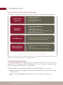
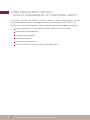
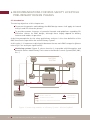
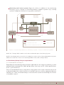
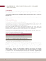
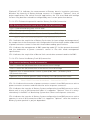
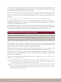
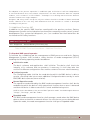
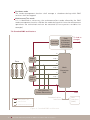
© C.Dupont/CEA
Functional and Safety Guide for
Battery Management System (BMS)
assessment and certification
“BUREAU VERITAS”, and the Bureau Veritas 1828 device are registered
trademarks and are owned by BUREAU VERITAS SA.
All information provided in the Functional and Safety Guide for Battery
Management System (BMS) assessment and certification for the purpose
of clarification of BMS safety design and integration in Battery System are
protected by copyright and are the property of Bureau Veritas Certification
unless otherwise stated. No part of the documents may be reproduced,
copied, downloaded or transmitted, in any form and by any means, without
the prior written consent of Bureau Veritas Certification.
No express or implied licence or right of any kind is granted regarding
any information contained in the document, any trademarks or other
intellectual property rights of Bureau Veritas Certification or any third
party.
In no event shall Bureau Veritas Certification, its agents, consultants,
and subcontractors, be liable for special, indirect or consequential
damages resulting from or arising out of the use of the Functional and
Safety Guide for Battery Management System (BMS) assessment and
certification, including, without limitation, loss of profit or business
interruptions, however these may be caused.
Every effort is made to provide general information. However,
Bureau Veritas Certification does not guarantee the accuracy,
completeness, adequacy or usefulness of the content of the
documents, including but not limited to, any information, product,
service or process disclosed herein. Bureau Veritas Certification
hereby disclaims all warranties and guarantees, whether
expressed or implied, including any warranty of merchantability,
fitness for a particular purpose or use, or non-infringement of
third party rights with respect to the documents provided.
Copyright © 2014 Bureau Veritas Certification, All rights reserved.
Table of Contents
1. INTRODUCTION
1.1. Purpose
1.2. Scope
1.3. Structure
2. DEFINITIONS AND ACRONYMS
2.1. Definitions
2.1.1. Standard Terms
2.1.2. Verbal forms
2.2. Acronyms
4
8
8
8
8
10
10
10
10
11
3. REFERENCES
3.1. Normative references
3.1.1. IEC
3.1.2. CENELEC
3.1.3. Other standards
3.2. Informative references
14
14
14
14
15
15
4. GENERALITIES
4.1. State of the art of Electric Battery Technologies
4.2. Targeted Battery Applications
4.3. Battery Management System origins and description
18
18
18
19
5. BMS DEVELOPMENT PROJECT - QUALITY MANAGEMENT
OF FUNCTIONAL SAFETY
22
6. RECOMMANDATIONS FOR BMS SAFETY LIFECYCLE PRELIMINARY
DESIGN PHASES
6.1. Introduction
6.2. Preliminary Safety lifecycle requirements
6.2.1. Hazard and risk analysis
6.2.2. SIL allocation
24
24
25
25
27
Functional and Safety Guide for BMS assessment and certification
7. EXAMPLE OF BMS FUNCTIONAL AND ORGANIC BREAKDOWN
7.1. Introduction
7.2. Standard BMS functions
7.2.1. Safety Function (SF): Protect the Battery Pack
7.2.1.1. SF1: Monitor the Battery Pack State
7.2.1.2. SF2: Estimate the potential need for Battery Pack (dis)connection
7.2.1.3. SF3: Control the Battery Pack (dis)connection
7.2.2. P
erformance Function (PF): Optimize Battery life-time and
energy availability
7.2.3. Additional Functions (AF)
7.3. Standard BMS operating modes 7.4. Standard BMS architecture
7.5. Safety requirements for BMS hardware/software architecture
and design
8. RECOMMANDATIONS FOR BMS DESIGN TESTING AND
VALIDATION ACTIVITIES
8.1. Introduction
8.2. General requirements
8.2.1. Configuration of the validation platform
8.2.2. Safety User Manual
8.3. Validation of safety requirements - Abuse test procedures
8.4. Performance and endurance tests
30
30
30
30
30
31
31
32
33
33
34
35
38
38
38
38
38
39
40
Table of Figures
FIGURE 1. Secondary Battery Technologies Overview
18
FIGURE 2. Interacting modules of a Battery System - Monitoring BMS
24
FIGURE 3. Interacting modules of a Battery System - Control & Monitoring BMS 25
FIGURE 4. Standard BMS architecture
34
Functional and Safety Guide for BMS assessment and certification
5
1
1.Introduction
1.INTRODUCTION
1.1.Purpose
This document gives safety recommendations for Battery Management Systems (BMS)
development.
Embracing the IEC 61508 safety principles, including E/E/PE system safety lifecycle
decomposition, it describes Bureau Veritas Certification guidelines and acceptance
criteria at each of the following phases of BMS development:
Risk analysis preliminary studies
Functional specification and SIL allocation
Architecture description
Testing and Validation activities
This document is applicable to BMS design and validation teams, as well as Battery System
integrators and BMS third-party safety assessors.
1.2.Scope
This guide applies to the development of generic BMS, as independent as possible from
electric battery technology and industrial application.
Recommendations related to specific electric battery chemistry and/or specific batterypowered applications are tagged as such.
In this guide, the scope delimitation of a generic BMS is mainly driven by functional
considerations. As described hereinafter, an elementary BMS shall manage a set of
primary safety functions achieving battery protection. Performance functions may
be added to the BMS scope, on condition that they have no impact on safety function
behaviour.
1.3.Structure
Following some introductory chapters (chapters 1 to 4), this document endorses in
chapter 5 the IEC 61508 quality notion of “Management of Functional Safety” applied to
BMS development projects.
In chapter 6, it provides generic guidelines and specific examples for BMS design
preliminary phases: risk analysis studies and Safety Integrity Level (SIL) allocation.
Then, in chapter 7, the functional and organic breakdown of a generic BMS is considered.
Recommendations for BMS testing and validation activities are presented in chapter 8.
8
Functional and Safety Guide for BMS assessment and certification
2
2.Definitions and acronyms
2.DEFINITIONS AND ACRONYMS
2.1.Definitions
2.1.1.Standard Terms
Battery Management System (BMS): Electronic system associated with a battery pack
which monitors and/or manages in a safe manner its electric and thermal state by
controlling its environment, and which provides communication between the battery
system and other macro-system controllers (e.g.: Vehicle Management System (VMS) and
Energy Management System (EMS)).
Battery Support System (BSS): A group of interconnected and interactive parts that
perform an essential task as a component of a battery system.
NOTE: Such systems are, for example, electrolyte circulation pumps, cooling and heating devices or
fire extinguishers.
Battery System: Energy storage device that includes cells, cell assemblies or battery
pack(s) as well as electrical circuits and electronics (Example of electronics: BMS, BSS,
cell electronics).
Cell electronics: Electronic device that collects and possibly monitors thermal and
electric data of cells or cell assemblies and contains electronics for cell balancing, if
necessary, as well as over-current protection devices (e.g. fuse).
NOTE: The cell electronics may include a cell controller. The functionality of cell balancing may be
managed by the cell controller as part of a modular BMS.
Rated capacity: Supplier’s specification of the total amount of Ampere Hours that can
be withdrawn from a fully charged battery pack or system for a specified set of test
conditions, such as discharge rate, temperature and discharge cut-off voltage.
Secondary battery: Rechargeable battery. Known as secondary cells because their
electrochemical reactions are electrically reversible.
State of charge (SOC): Available capacity in a battery pack or system, used to estimate the
current charge level of a battery in use.
State of health (SOH): Available capacity in a battery pack or system as a function of the
battery lifetime.
NOTE: SOC and SOH are expressed as percentages of rated capacity.
2.1.2.Verbal forms
Might / may / can: When referring to the Applicant, indicates a possible action.
Shall / must: Indicates a mandatory requirement to be followed by the Applicant.
Should: Indicates a recommendation or preferred course of action, but does not exclude
other possible options which would be examined on a case by case basis.
10
Functional and Safety Guide for BMS assessment and certification
2.2.Acronyms
AF
Additional Function
Ah
Ampere hours
BCS
Battery Charging System
BMS
Battery Management System
CAN
Controlled Area Network
DSP
Digital Signal Processor
E/E/PE
Electrical/Electronic/Programmable Electronic
EMS
Energy Management System
EV
Electric Vehicle
GND
Ground
HEV
Hybrid Electric Vehicle
HMI
Human-Machine Interface
LOPA
Layer of Protection Analysis
PCS
Power Conversion System
PF
Performance Function
PFH
Probability of Failure on Demand
(P-M-C)MU
(Pack - Module - Cell) Management Unit
SIL
Safety Integrity Level
SF
Safety Function
SOC
State of Charge
SOH
State of Health
THR
Tolerable Hazard Rate
UPS
Uninterruptible Power Supply
VMS
Vehicle Management System
Wh
Watt hours
Functional and Safety Guide for BMS assessment and certification
11
3
3.References
3.REFERENCES
For the sake of brevity, only the main standards are listed here. The complete certification
references mentioned by Bureau Veritas Certification are available upon request.
3.1.Normative references
3.1.1.IEC
Designation
Title
IEC 61508 (Part 1
to 7) - Edition 2.0
Functional safety of electrical/electronic/programmable
electronic safety-related systems
IEC 61851
(Part 1 – 2010)
Electric vehicle conductive charging system – General
requirements
IEC 61427-2
(Draft 21/825A/CD)
Secondary cells and batteries for renewable energy storage –
General requirements and methods of test – Part 2: on-grid
applications
IEC 61850
Communication networks and systems in substations
IEC 60950-1
Information technology equipment - Safety - Part 1: General
requirements
Table I. IEC normative references
3.1.2.CENELEC
Designation
Title
NF EN 50272
(Part 1 – 2010 / 2 –
2005 / 3 – 2003)
Safety requirements for secondary batteries and battery
installations
NF EN 61982 - 2013
Secondary batteries (except lithium) for the propulsion of
electric road vehicles – Performance and endurance tests
NF EN 62133 - 2013
Secondary cells and batteries containing alkaline or other
non-acid electrolytes - Safety requirements for portable sealed
secondary cells, and for batteries made from them, for use in
portable applications
Table II. CENELEC normative references
14
Functional and Safety Guide for BMS assessment and certification
3.1.3.Other standards
Designation
Title
ISO 26262 - 2011
Road vehicles - Functional safety
ISO 12405 (Part 1 2011 / 2 - 2012)
Electrically propelled road vehicles – Test specification for
lithium-ion traction battery packs and systems
IEEE Std 1625 - 2008
IEEE Standard for Rechargeable Batteries for Multi-Cell Mobile
Computing Devices
Table III. Other normative references
3.2.Informative references
Designation
Type
Authors
Title
978-3-9810801-8-6/
DATE12/
©2012 EDAA Publication
Publication
M. Brandl, H. Gall, M.
Wenger, V. Lorentz, M.
Giegerich, F. Baronti, G.
Fantechi, L. Fanucci, R.
Roncella, R. Saletti, S.
Saponara, A. Thaler, M.
Cifrain, W. Prochazkat
“Batteries and
Battery Management
Systems for Electric
Vehicles”
W56HZV-11-C-0194–
2012 Journal Article
Publication
B. Pilvelait, C. H. Rentel,
W. Finger, L. Ruckman, D.
Fogg, G. L. Plett, M. Marcel
“Performance
results for a
universal lithium ion
Battery Management
System”
0278-0046/03$17.00
©2003 IEEE Publication
Publication
J. Chatzakis, K. Kalaitzakis, “Designing a New
N. C. Voulgaris, S. N.
Generalized Battery
Manias
Management System
Table IV. Informative references
Functional and Safety Guide for BMS assessment and certification
15
4
4.Generalities
4.GENERALITIES
4.1.State of the art of Electric Battery Technologies
The figure 1 outlines the primary existing technologies for secondary batteries design.
Conventional
Batteries
• Lead-based Batteries
Pb-acid / Pb-C
• Nickel-based Batteries
NiCd / NiMH
Advanced
Batteries
• Lithium-based Batteries
Li-ion / LMP
• Sodium-based Batteries
High-temperature - Sodium Sulphur (NaS)
• Hydrogen Cells / Fuel Cells
Flow Batteries
• Energy is stored as the electrolyte material
• Liquid electrolyte (Vanadium, ZnBr)
Supercapacitors
Ultracapacitors
• Capacitors without conventional solid
dielectric
• Families depending on electrode design
Figure 1. Secondary Battery Technologies Overview
NOTE: The safety functions carried out by a BMS are mainly relevant for Advanced Battery operation
(especially Lithium-based Batteries), as explained in §4.3.
4.2.Targeted Battery Applications
Low-energy applications using miniature or portable batteries (<100 Wh) such as
capacitors are considered outwith this guide scope as the concept of safety and fault
gravity related to these batteries is questionable.
This guide applies to Mid-energy and High-energy Battery applications, such as:
atteries for stationary applications (Emergency Power (UPS), Local Energy storage,
B
Smart Grids…)
Batteries for embedded applications (EVs, HEVs, Locomotives, Airplanes…)
18
Functional and Safety Guide for BMS assessment and certification
4.3.Battery Management System origins and description
BMS development has stemmed from the emergence of Lithium-based batteries which,
unlike conventional Nickel-based batteries, do not tolerate any overvoltage and may
require secondary functions to work safely (heating, etc…).
Hence, two relevant functions for a Battery Management System were highlighted:
Overvoltage Protection, as a safety-related battery protection action
Accurate cell balancing, as functionality in the service of energy storage
performance optimization
Those two particular functions of a BMS symbolize the BMS functional breakdown
philosophy adopted in the following chapters: safety functions related to Battery
Protection combined with performance functions related to battery lifetime and energy
availability optimization.
Functional and Safety Guide for BMS assessment and certification
19
5
5.BMS Development project Quality management
of functional safety
5.BMS DEVELOPMENT PROJECT QUALITY MANAGEMENT OF FUNCTIONAL SAFETY
To properly manage and achieve functional safety of Battery Management Systems,
project development teams shall apply the quality requirements of IEC 61508-1 §6.
In particular, the following project aspects shall be specified and applied accordingly:
Project organization (responsibility sharing, communication, planning)
Documentation management
Configuration procedures
Modification process
Requirement management
Functional Safety assessment means (periodic audits)
22
Functional and Safety Guide for BMS assessment and certification
6
6.Recommandations
for BMS safety lifecycle
preliminary design phases
6.RECOMMANDATIONS FOR BMS SAFETY LIFECYCLE
PRELIMINARY DESIGN PHASES
6.1.Introduction
The two key objectives of this chapter are:
o present the generic methodology that BMS design teams shall apply for hazard
T
analysis and SIL allocation phases.
o provide common instances of potential hazards and guidelines regarding SIL
T
allocation choices for BMS design, although these largely depend on battery
features and modes of operation.
A decisive prerequisite for the safety preliminary analyses is the clear definition of the
BMS functional scope within the overall Battery System.
At this point, it is important to distinguish between the two main BMS categories (please
refer to §2.2 for acronyms signification):
Monitoring systems (figure 2), whose function is to provide valid information and
potential alarms about Battery Pack state to the Master Control System (EMS, VMS,
etc…).
BATTERY
SYSTEM
HMI
EMS
BMS
BSS
Battery Pack
Charger
(BCS, PCS)
Power
supply
••
••
••
Loads
Power contactor
Main power
Communication link
BMS scope
Potential communication link
Figure 2. Interacting modules of a Battery System - Monitoring BMS
24
Functional and Safety Guide for BMS assessment and certification
M
onitoring and Control systems (figure 3), which, in addition to the monitoring
functions, are in charge of controlling Battery Support Systems (e.g. cooling
systems) and power electronics (e.g. power contactors).
BATTERY
SYSTEM
HMI
EMS
BMS
BSS
Battery Pack
Charger
(BCS, PCS)
Power
supply
••
••
••
Loads
Power contactor
Main power
Communication link
BMS scope
Potential communication link
Figure 3. Interacting modules of a Battery System - Control & Monitoring BMS
NOTE: The “Charger (BCS)” module can also be considered as part of the Battery System.
NOTE II: According to project characteristics and project teams’ choices, Battery Management Systems
(BMS) can include one or more of the following modules: BSS / HMI / Charger (BCS).
6.2.Preliminary Safety lifecycle requirements
6.2.1.Hazard and risk analysis
Regarding the methodology and techniques applicable for the analyses of battery system
hazards and associated risks, BMS design teams shall rely on IEC 61508 specifications
(Part 1 §7.4 and Part 5).
Prior to hazard identification, safety teams shall agree on the scope of entities which are
to be protected by the safety functions of the BMS: persons, nature, equipment (battery
lifetime), etc…Then, the hazard analysis shall take into account the following two classes
of hazardous events:
Functional and Safety Guide for BMS assessment and certification
25
i. Chemical, electrical and environmental hazards coming from Battery System operation
The non-exhaustive table below lists potential hazards tied to the Battery System
operation:
Chemical, electrical and environmental hazards coming from Battery System
operation
Hazards coming from Battery Pack chemical reactions
Emission of combustible, toxic or explosive gases
Emission of combustible, toxic or corrosive liquids
Thermal runaway
Electrolyte creepage
Cell fire or explosion
Cell overheating
Hazards coming from Battery System electrical circuitry
Internal short-circuit
Loss of internal electrical continuity
Excessive internal impedance
Massive shorts in power output cabling to the PCS
Hazards coming from Battery System environmental conditions
Seismic events
Fire in immediate vicinity of the battery
Sprinkler action, drip-water exposure and flooding
Crushing of cells due to rack or building collapse
Vandalism and theft
Operator errors
Table V. Potential Hazards related to Battery System operation
26
Functional and Safety Guide for BMS assessment and certification
ii.Hazards coming from the BMS operation within the Battery System
The non-exhaustive table below lists typical potential hazards related to the failure of
monitoring, control and safety functions within the Battery System.
Between brackets are identified modules of BMS which are related to each hazard.
Hazard coming from the BMS operation within the Battery System
Loss of air conditioning and battery cooling (BSS)
Loss of battery heating controls (BSS)
Loss of battery voltage control function (BMS / EMS)
Over-discharge of cells due to a ground fault or control function loss (BMS/EMS)
Overcharge due to control function loss, data drift or software error (BMS/EMS)
Overcurrent due to control function loss or shunt calibration error (BMS/EMS)
Short-circuit in control and diagnostic cabling on the battery (BMS)
Loss of communication between control systems (BMS/EMS)
Loss of BMS/BSS functionality
Table VI. Potential Hazards related to BMS operation within the Battery System
Once the hazard analysis has been carried out on the Battery System, safety teams shall
tackle the following two points:
Select the hazards which are to be mitigated by BMS action
Estimate the risks associated with the above-mentioned hazards, based on their
quantified probability and severity
This stage primarily depends on project specificities: adopted battery technology,
planned mode of operation, environment, etc. That is why it should be carried out in close
collaboration between the battery manufacturer, the battery system developer (project
and safety teams) and the future integrator/operator.
6.2.2.SIL allocation
Safety teams shall follow the standard IEC 61508 (Part 5) requirements concerning the
techniques (e.g. quantitative and semi-quantitative methods) and measures to allocate
Safety Integrity Levels (SIL) to risks.
Risks estimated through preliminary analyses shall be compared with project safety
objectives in order to evaluate their tolerable rates of occurrence (THR). These rates
determine the SIL attribution to corresponding safety functions.
Functional and Safety Guide for BMS assessment and certification
27
The following table is based on IEC 61508 Ed2 and ISO 26262 standards. It defines the
correspondence between Safety Integrity Level, Automotive Safety Integrity Level and
dangerous failure frequency of the safety function:
Safety Integrity
Level (SIL)
Automotive Safety
Integrity Level (ASIL)
Average frequency of a dangerous
failure of the safety function [h-1]
4
D
≥10-9 to <10-8
3
B and C
≥10-8 to <10-7
2
-
≥10-7 to <10-6
1
-
≥10-6 to <10-5
Table VII. Correspondence between (A)SIL and dangerous failure frequency
of the safety function
§7.2.1 of the present document lists the typical generic BMS functionalities which
require a SIL allocation, in the sense that their failure can lead to a hazardous event in an
intolerable probability, as defined in the previous paragraph.
It is recommended to develop those safety functions according to a “SILX” (X=1 to 4) as
specified in the generic standard IEC 61508 - or an “ASILX” (X=A to D) as specified in the
standard ISO 26262 for road vehicle applications.
This effort may be sufficient for a “SILX” (respectively “ASILX”) certification of the whole
Battery Management System, if the following condition is reached:
I ndependence between safety and non-safety BMS function behaviors is proven
(refer to IEC 61508 for details about independence evidence, especially Annex F of
Part 3).
28
Functional and Safety Guide for BMS assessment and certification
7
7.Example of BMS functional
and organic breakdown
7.EXAMPLE OF BMS FUNCTIONAL AND ORGANIC
BREAKDOWN
7.1.Introduction
This chapter discusses further Battery Management System generic functions, architectures and behaviors.
The following considerations are intended for Battery Monitoring and Control Systems as
defined in §6.1.
NOTE: Generally, Battery Monitoring Systems functions are a subset of Battery Monitoring and Control
Systems functions.
7.2.Standard BMS functions
7.2.1.Safety Function (SF): Protect the Battery Pack
As introduced in the previous sections, the following paragraph lists BMS functions that
shall, unless proven otherwise, be developed according to a SIL process (refer to IEC
61508 for the corresponding normative requirements).
Here, safety shall be understood as the protection of persons and assets. Hence, the
following functions’ role is to protect the Battery Pack from human and assets-related
hazardous events (explosion, electric shock, emission of toxic substances).
The functions are presented through a Sensor / Logic / Actuator view (SF1 / SF2 / SF3).
7.2.1.1.SF1: Monitor the Battery Pack State
SF1: Monitor the Battery Pack State
SF1-1: Measure battery cell and pack Voltage
SF1-2: Measure battery cell and pack Temperature
(Optional) SF1-3: Measure battery pack Current Flow
(Optional) SF1-4: Detect battery system Leakage Currents
Table VIII. BMS Functional breakdown - Sub-functions of SF1
SF1-1 & 2 indicate the measurement of Battery voltage and temperature characteristics
by BMS sensors, and the transfer of this information to the BMS processor unit.
Preliminary safety and design studies (§6.2) shall examine the architecture of BMS
sensors (positioning, number, redundancies, etc…) that enables the allocated SIL to be
reached.
(Optional) SF1-3 indicates the measurement of Battery Pack Current Flow by BMS
sensors, and the transfer of this information to the BMS processor unit. It is tagged
as “Optional” since over-current protection functions can be handled automatically by
electronic components (e.g fuse, circuit breaker) which does not require BMS control.
30
Functional and Safety Guide for BMS assessment and certification
(Optional) SF1-4 indicates the measurement of Battery electric insulation resistance,
based on the intensity of Battery leakage currents. It is tagged as “Optional” since, on
project applications like vehicle traction applications, the risk associated with leakage
currents may be either tolerable or mitigated by over-current protection devices.
7.2.1.2.SF2: Estimate the potential need for Battery Pack (dis)connection
SF2: Estimate the potential need for Battery Pack (dis)connection
SF2-1: Determine battery pack critical state
SF2-2: Manage operating modes
SF2-3: Receive information from Master Control System (EMS, VMS…)
Table IX. BMS Functional breakdown - Sub-functions of SF2
SF2-1 indicates the acquisition of Battery Pack status (at least voltage and temperature),
the comparison of these measures with configured critical thresholds and the elaboration
of power contactors control in line with threshold exceeding specifications.
SF2-2 indicates the management of BMS operating mode (§7.3 of the present document)
and the elaboration of power contactors control in line with mode management
specifications.
SF2-3 indicates the acquisition of Master Unit control data communicated to the BMS.
7.2.1.3.SF3: Control the Battery Pack (dis)connection
SF3: Control the Battery Pack (dis)connection
SF3-1: Control the (dis)connection of the electric line of charge
SF3-2: Control the (dis)connection of the electric line of discharge
(Optional) SF3-3: Inform Master Control System (EMS, VMS…) of Battery Pack
(dis)connection status
(Optional) SF3-4: Inform operator (HMI) of Battery Pack (dis)connection status
Table X. BMS Functional breakdown - Sub-functions of SF3
SF3-1 & 2 indicate the transfer of power contactors controls from BMS processor unit to
power contactors actuators and the effective action on power contactors.
SF3-3 indicates the transfer of Battery System configuration from BMS processor unit to
Master unit in case of (dis)connection order. It is tagged as “Optional” since it is safetyrelated only if the BMS is a Monitoring System that cannot control power contactors.
SF3-4 indicates the transfer of Battery System configuration from BMS processor unit to
operator in case of (dis)connection order. It is tagged as “Optional” since the need for a
Battery System operator is project-dependent.
Functional and Safety Guide for BMS assessment and certification
31
In addition to the above mentioned safety functions, BMS designing and integrating teams
shall estimate, during preliminary safety analyses, if a “Manual Shut-off function” needs
to be implemented on the Battery Pack (System).
NOTE: If the Battery System includes a Battery Support sub-system BSSx whose function has been
identified as safety-related (e.g. fire extinguisher) and if the BMS is in charge of controlling this subsystem, the safety function “Control and Monitor the BSSx” shall be considered as part of the present
paragraph.
7.2.2.Performance Function (PF): Optimize Battery life-time and energy availability
The following BMS functions role is the real-time regulation of Battery Pack electrical
and thermal characteristics, whose long term objectives are the Battery Pack life-time
and energy availability optimization.
As explained in the previous sections, whether or not “Battery Pack life-time optimization”
is a safety issue depends on project features and preliminary hazard analyses. If identified
as such, the following functions shall be considered as safety functions of §7.2.1.
PF: Optimize Battery life-time and energy availability
PF1: Monitor and Control Battery Pack State of Charge (SOC) and State of Health (SOH)
PF2: Manage cell balancing
PF3: Monitor and Control non-safety Battery Support Systems (BSS)
Table XI. BMS Functional breakdown - Sub-functions of PF
PF1 indicates the estimation of Battery Pack SOC and SOH using Battery electrical
measurements (SF1), and the elaboration of power electronics and/or battery charger
and/or load controls to optimize battery charge and discharge.
PF2 indicates the control of individual cell (dis)connection to the electric battery line
based on cell electrical measurements (SF1) to optimize battery energy capacity.
PF3 indicates the monitoring and control of non-safety Battery Support Systems (e.g.
battery cooling and heating sub-systems) used for Battery electrical and thermal
characteristics regulation.
NOTE: The present BMS functional breakdown separates the software function of “Battery Pack state
estimation” into two sub-functions:
A safety sub-function, hereinabove identified as SF2-1, which determines the Battery critical
state. As broached in §7.2.1.2, this function is based on a simple algorithm that compares Battery
electrical and thermal measurements with critical thresholds.
A non-safety sub-function, identified as PF1, which estimates the Battery State of Charge (SOC)
and State of Health (SOH) for Battery performance optimization purpose. It is based on a more
complex program, largely depending on Battery technology, application and choice of observer
model for SOC and SOH estimator.
32
Functional and Safety Guide for BMS assessment and certification
The adoption of the present separation is conditional upon verification of sufficient independence
of execution between these two software sub-functions. For more information about the required
evidence, refer to Annex F of IEC 61508-3: “Techniques for achieving non-interference between
software elements on a single computer”.
Designers and safety teams can opt for only one software function to handle all above mentioned
actions. However in this case they shall demonstrate that this function as a whole is developed
according to a SIL process.
7.2.3.Additional Functions (AF)
In addition to the specific BMS functions mentioned in the previous sections, Battery
Management Systems can include other functionalities commonly used in control systems
developments (e.g. system fault diagnostic, etc...) on condition that their behaviours do
not interfere with safety functions.
Additional Functions (AF)
AF1: Diagnostic - Record Battery life history log
Table XII. BMS Functional breakdown - Additional Functions
7.3.Standard BMS operating modes
To facilitate the scheduling and the management of BMS processes and tasks, Battery
Management Systems shall include a safety function of mode management (SF2-2)
handling the following operating modes breakdown:
I nitialization mode
The basic software and applications shall initialize. The device shall check the
integrity of its software and run autotests if necessary. It shall then take into
account its different configuration files and the content of the non-volatile memory.
onfiguring mode
C
The configuring mode shall be the mode during which the BMS device is able to
receive, check and take into account additional configuration data sent by its main
EMS/VMS device (master/slave relation).
Normal Operation mode
The operation mode offered by the BMS mode management function shall be the
mode during which the device is fully operational. It means that no error is detected
and that the device is able to execute its Control and Monitoring tasks.
NOTE: A further breakdown of the present BMS “Operation mode” should distinguish between
“Charge”, “Discharge”, and “Idle” modes.
Degraded mode
The BMS mode management function shall manage a mode when the BMS device
detects either an internal or external failure. If a critical error occurs during Normal
Operation mode, the mode management function shall go to Degraded mode.
Functional and Safety Guide for BMS assessment and certification
33
Shutdown mode
The mode management function shall manage a shutdown during which BMS
services shall be stopped.
Maintenance/Test mode
If it is identified as necessary, the maintenance/test mode offered by the BMS
mode management function shall be the mode during which intrusive maintenance
operations are authorized and can be executed (to force process variables for
example).
7.4.Standard BMS architecture
Pack
Protection
& Charge /
Discharge
Switching
Current
Sensing
To load or
charger
V3
Super
Cell 3
Fuse
Temp 3
•••
Cell 3
Cell 2
Cell 1
V2
Super
Cell 2
Temp 2
V1
Super
Cell 1
Main
Processor
Unit
Temp 1
Cell Balancer
Power Electronics
Communication
interface
Main power line
Sensor link
Communication link
Figure 4. Standard BMS architecture
34
Functional and Safety Guide for BMS assessment and certification
GND
User
interface
(HMI)
Several BMS architectures have already been commercialized, or are at the development
stage. The present document does not aim to reject any of those BMS architecture
choices, so long as they respect hardware safety requirements identified during the
BMS design preliminary analyses.
Nevertheless, figure 4 illustrates the essential organs that should exist in any BMS
device:
C
ell temperature and voltage sensors
B
attery Pack Current Flow sensor
P
rocessor Unit
P
ower contactors
C
ell electronics
C
ommunication interface
NOTE: BMS “intelligence” can also be distributed in modular BMS architectures (PMU / MMU / CMU,
cell electronics). If so, communication means between the different units shall be managed safely.
7.5.Safety requirements for BMS hardware/software architecture and design
Please refer to IEC 61508-2 and IEC 61508-3 for specific requirements regarding BMS
hardware components architecture and software module design, inherited from system
safety requirements.
Information technology hardware (e.g. electrical circuits and electronics) design and
architecture should respect the safety requirements of IEC 60950-1, particularly concerning the reduction of the following risks:
Electric shock
Energy related hazards
Fire
Heat related hazards
Mechanical hazards
Radiation
Chemical hazards
With regards to the compatibility and safety of communication protocols between
Battery System internal and external controllers, designers should refer to IEC 61850
requirements.
Finally, BMS developers should consult the standard IEC/TS 61000-1-2 regarding the
issue of electromagnetic compatibility.
Functional and Safety Guide for BMS assessment and certification
35
© C.Dupont/CEA
8
8.Recommandations for
BMS design testing and
validation activities
8.RECOMMANDATIONS FOR BMS DESIGN TESTING
AND VALIDATION ACTIVITIES
8.1.Introduction
This final section provides recommendations and guidelines for Battery Management
System design testing and validation activities.
Again, the chosen SIL-dependent validation methodology and techniques shall be in
accordance with the IEC 61508 requirements.
Here, it is assumed that the Battery Pack has already been validated at the battery
manufacturer level (especially regarding resistance to mechanical shocks and protection
against short-circuits and over-current between cells).
BMS development teams shall have access to the battery manufacturer specifications,
validation procedures and reports.
8.2.General requirements
8.2.1.Configuration of the validation platform
Compatibility between all the systems implied (e.g. BMS, EMS/VMS, laboratory’s testing
ground, test-bench) must be checked before testing.
The battery system shall enable the tests run, i.e. via specified test modes implemented
in the BMS, and shall be communicable with the test bench via common communication
buses.
The battery system shall be controlled by the BMS. The test bench equipment shall follow
the operational limits provided by the BMS via bus communication.
The test bench equipment shall maintain the on/off requirements for the main contactors
and the voltage, current and temperature profiles according to the requirements of the
given test procedure.
The Battery Support Systems shall be operational according to the controls by the BMS,
unless otherwise specified in the test procedure.
If an external power source provides energy to the BMS, this energy must be recorded
and declared.
8.2.2.Safety User Manual
To ensure a safe integration and operation by end-users, a safety user manual gathering
all the BMS safety exported constraints shall accompany the delivery of the validated
BMS.
This manual shall contain:
A functional specification of the functions capable of being performed
Identification of the hardware and/or software configuration of the validated BMS
Constraints on the use of the BMS
Assumptions surrounding the analyses of the behaviour or failure rates of the BMS
38
Functional and Safety Guide for BMS assessment and certification
In particular, the definition (scope of tests, frequency) of required BMS proof tests and
other maintenance activities shall appear in this document.
For a complete description of the required content of a Safety User Manual, please refer
to standard IEC 61508 (Part 2 and 3 Annex D).
8.3.Validation of safety requirements - Abuse test procedures
After each test, the Battery Pack shall be observed until it is considered safe to handle.
Data sampling, especially for Battery Pack voltage and current, shall be performed using
an adequate sampling rate (e.g. 0,1ms for evaluation of the current shut-off function and
the real short-circuit current peak).
The behaviour of the Battery Management System shall be fully validated regarding the
following non-exhaustive abuse test procedures:
Overcharge / Over discharge
The test shall be performed with integrated passive circuit protection devices
operational. BMS active charge control function shall be inhibited.
The BMS shall interrupt the overcharge / over discharge current by an automatic
disconnect of the main contactors.
Cell Over-heating
The test shall be performed with an inhibited Battery Pack cooling control function.
The test objective is to validate the BMS functionality of cell over-heating protection
with the disconnection of power contactors and the potential start-up of safety
Battery Support Systems (e.g. fire extinguisher).
Loss of BSS / BMS safety function
The purpose of this test is to ensure that any BMS safety function failure (e.g freezed
sensor value) is detected within a controllable period of time and that the outputs of
the degraded BMS place the Battery System in a safe state.
Loss of communication with Master Control System
The purpose of this test is to ensure that any lost or corrupted information from
Master Control System communication is detected within a controllable period of
time and that the outputs of the degraded BMS place the Battery System in a safe
state.
Corruption of safety-related software
The test aims to confirm that BMS autotests detect the introduction of corrupted
data within safety-related software and configuration files and that the mode
management function places the Battery System in a safe state.
(Optional) Short-circuit / Over-current
The purpose of the short-circuit / over-current protection test is to check the
functionality of the overcurrent protection device (e.g. fuse) and/or automatic
disconnect by the main contactors. The BMS shall interrupt the over-current.
Measures of insulation resistance between the Battery Pack case and the positive
and negative terminals can be carried out before and after the test.
Functional and Safety Guide for BMS assessment and certification
39
8.4.Performance and endurance tests
The three main test categories for estimating Battery System performance are energy
tests, power tests and lifetime tests.
Although BMS performance requirements largely depend on Battery technologies
and Battery System applications, the following non-exhaustive table lists typical BMS
performance tests required by Battery System integrators:
Typical BMS performance tests
Energy and capacity at different temperatures and discharge rates
Power and internal resistance
No-load SOC loss
SOC loss at storage
Cranking power at high temperature
Energy efficiency
Cycle life
Table XIII. Typical BMS performance and endurance tests
For more information about application-specific Battery system performance required
tests, please refer to:
Traction Batteries for Electric Vehicle application
- Li-ion technology: ISO 12405 / IEC 62660
- Other: NF EN 61982
Batteries for Renewable Energy storage on-grid application: IEC 61427-2 Ed 1.0
40
Functional and Safety Guide for BMS assessment and certification
This technical guide was developed
by experts in the Bureau Veritas
functional safety team responsible
for the IEC 61508 certification, in
coordination with CEA and LCIE.
© - Copyright Bureau Veritas Certification, Photos: C.Dupont/CEA, Shutterstock - All rights reserved | BMS_V0 001 2014
Bureau Veritas Certification France
Battery Management System Assessment & Certification
60, avenue du Général de Gaulle
92046 Paris La Défense cedex
[email protected]
www.bureauveritas.fr
LCIE Bureau Veritas
Batteries Verification & Testing
33, avenue du Général Leclerc
92260 Fontenay-aux-Roses
[email protected]
www.lcie.fr