1
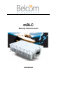
mBLC
Block Up Converter Series
User Manual
mBLC User Manual
Contacting Belcom
The following information is provided for your use. Please feel free to contact us
at Belcom Microwaves Ltd.
Address:
Belcom Microwaves Ltd.
Ramat Gabriel Industry Park
P.O Box 907, Migdal Ha’emek, 23101
ISRAEL
Phone:
(972) 4 6417600
Fax:
(972) 4 6417628
www.belcommicrowaves.com
Printed in Belcom
July 2013
Copyright
Copyright 2013 Belcom Microwaves Ltd. All rights reserved.
This manual has been published by Belcom Microwaves Ltd. and supplied on
condition that it is used solely for the purpose of supporting the operation,
service, and maintenance of Belcom Microwaves Ltd. equipment. Mutually
accepted provisions of the contract with Belcom Microwaves Ltd. will govern the
rights of the customer with respect to this manual. This manual shall not be
duplicated, released, disclosed or used, in whole or in part, for any purpose
other than that stated herein, without the express written permission of Belcom
Microwaves Ltd. The contents of this document are subject to change without
prior notice.
List of Updates
No.
i
Date
Description
Page Number
1.0
September 2009
New release
All
2.0
July 2013
Major revision
All
mBLC User Manual
Preface
Table of Contents
1.
Introduction ................................................................................................................ 1-1
1.1
1.2
1.3
1.4
1.5
2.
Handling, Installation and Operation ................................................................... 2-1
2.1
2.2
2.3
2.4
3.
Overview ......................................................................................................... 1-1
Features and Benefits .................................................................................. 1-2
Available Models and Configurations ........................................................ 1-3
Technical Data and Specifications ............................................................. 1-4
General Description ...................................................................................... 1-6
Handling.......................................................................................................... 2-1
Labeling .......................................................................................................... 2-4
Packing List .................................................................................................... 2-5
Installation and Operation............................................................................ 2-6
Maintenance ............................................................................................................... 3-1
3.1
3.2
Preventive Maintenance .............................................................................. 3-1
Troubleshooting............................................................................................. 3-1
List of Figures
Figure 1-1:
Figure 1-2:
Figure 2-1:
Figure 2-2:
Figure 2-3:
mBLC series Outline..................................................................................... 1-1
General Description ...................................................................................... 1-6
mBLC Series Package Open View ............................................................ 2-3
Labeling .......................................................................................................... 2-4
Installing the mBLC Series .......................................................................... 2-6
List of Tables
Table 1-1: Available Models and Configurations ............................................................... 1-3
Table 1-2: Technical Data and Specifications ................................................................... 1-4
Table 2-1: Packing List ................................................................................................... 2-5
Table 2-2: IF Cable Maximum Permitted Resistance............................................................... 2-7
ii
mBLC User Manual
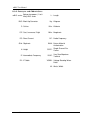
List of Acronyms and Abbreviations
mBLC series: Belcom low power ( 1 to 8
Watt) BUC series
BUC: Block Up Converter
C: Celsius
CIF: Cost, Insurance, Fright
DC: Direct Current
GHz: Gigahertz
L: Length
Kg: Kilogram
KHz: Kilohertz
MHz: Megahertz
RF: Radio Frequency
RMA: Return Material
Authorization
H: Height
SCPC: Single Channel Per
Carrier
IF: Intermediate Frequency
VSAT: Very Small Aperture
Terminal
IFL: IF Cable
VSWR: Voltage Standing Wave
Ratio
W: Watts, Width
iii
mBLC User Manual
Preface
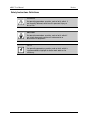
Safety Instructions Definitions
WARNING
An operating procedure, practice, and so forth, which, if
not correctly followed, could result in personal injury or
loss of life.
CAUTION
An operating procedure, practice, and so forth, which if
not strictly observed, could result in damage to or
destruction of equipment.
NOTE
An operating procedure, practice, and so forth, which is
recommended to highlight for better work order or for
efficiency.
iv
mBLC User Manual
Preface
Scope
This manual contains the operational procedures and activities performed on the
mBLC BUC series.
The manual consists of the following chapters:
Chapter 1:
Introduction
Introduction to the mBLC series.
Chapter 2:
Handling, Installation and Operation
Instructions on how to handle and install the mBLC
series BUCs.
Chapter 3:
Maintenance
Procedures that should be covered while using the
mBLC series BUCs.
Trobleshooting
Certificates
ISO 9001-2008 Certified Quality Management System
"Needs to demonstrate its ability to consistently provide
product that meets customer and applicable statutory and
regulatory requirements, and aims to enhance customer
satisfaction through the effective application of the system,
including processes for continual improvement of the system
and the assurance of conformity to customer and applicable
statutory and regulatory requirements."
v
mBLC User Manual
Preface
General Safety Guidelines
The mBLC BUC should be located in a Restricted Access Location (RAL) - access
should be allowed to service personnel only.
The mBLC BUC is required to be connected to the earthing of the building structure.
grounding is provided via the OMT waveguide flange and through the antenna pole.
All 8 screws connecting the unit to the OMT are to be securely tightened. The
installer shall verify that the antenna is bonded to the building structure ground.
The earthed side of the mBLC is connected to the shielding of the coax cable and
the shielding should be earthed in the building infrastructure.
Use local agency approved cable that complies with the appropriate temperature
and power ratings.
When servicing the mBLC BUC, obey all safety instructions related to transmitting
antennas maintenance.
WARNING
Always observe standard safety precautions during
installation, operation and maintenance of this product.
WARNING
Handle this product only as instructed in this manual. Do
not attempt to operate or maintain this product in a
manner not specifically stated in this manual.
CAUTION
Hot surface while in operation, do not touch.
vi
mBLC User Manual
1.
Chapter 1: Introduction
Introduction
This chapter serves as an introduction to the mBLC series. It includes the
following sections:
Section 1.1: Overview
Section 1.2: Features and Benefits
Section 1.3: Available Models and Configurations
Section 1.4: Technical Data and Specifications
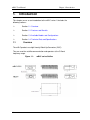
1.1
Overview
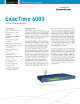
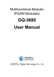
The mBLC products are high linearity Block-Up Converters (BUC).
They are used for satellite communication and operates at the C-Band
frequency range.
Figure 1-1:
1-1
mBLC series Outline
mBLC User Manual
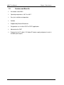
1.2
Chapter 1: Introduction
Features and Benefits
An outdoor sealed BUC
Operating temperature: -40°C to +60°C
Easy for installation and operation
Reliable
Supported by Belcom Microwaves
Designed for use in either VSAT or SCPC applications
Mounted on the OMT
Powered via the IFL cable ( 24V indoor DC power supply and power inserter is
available upon request.
1-2
mBLC User Manual
1.3
Chapter 1: Introduction
Available Models and Configurations
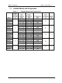
Table 1-1:
Output
Power
@ P1dB
(W)
Available Models and Configurations
Input
Frequency
(MHz)
950 - 1525
Output
Frequency
(GHz)
5.85 - 6.425
LO Frequency
(MHz)
4900
1075 - 1435
6.365 - 6.725
5290
975 - 1275
6.725 - 7.025
5750
mBLWC-1
950 - 1825
5.85 - 6.725
4900
mBLC-2
950 - 1525
5.85 - 6.425
4900
1075 - 1435
6.365 - 6.725
5290
975 - 1275
6.725 - 7.025
5750
mBLWC
950 - 1825
5.85 - 6.725
4900
mBLC-3
950 - 1525
5.85 - 6.425
4900
1075 - 1435
6.365 - 6.725
5290
975 - 1275
6.725 - 7.025
5750
mBLWC-3
950 - 1825
5.85 - 6.725
4900
mBLC-5
950 - 1525
5.85 - 6.425
4900
1075 - 1435
6.365 - 6.725
5290
975 - 1275
6.725 - 7.025
5750
mBLWC-5
950 - 1825
5.85 - 6.725
4900
mBLC-8
950 - 1525
5.85 - 6.425
4900
1075 - 1435
6.365 - 6.725
5290
975 - 1275
6.725 - 7.025
5750
Model
mBLC-1
mBLPA-1
mBLIN-1
mBLPA-2
mBLIN-2
mBLPA-3
mBLIN-3
mBLPA-5
mBLIN-5
mBLPA-8
mBLIN-8
1-3
1
2
3
5
8
Power
(W)
Weight
(Kg)
15
1.9
24
1.9
28
1.9
48
1.9
55
2.3
Consumption
mBLC User Manual
1.4
Chapter 1: Introduction
Technical Data and Specifications
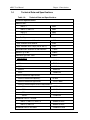
Table 1-2:
Technical Data and Specifications
Electrical Specifications:
Nominal Gain:
mBLC-1
53dB
mBLC-2, mBLC-3
55dB
mBLC-5
58dB
mBLC-8
60dB
Gain Stability:
Gain Variations over full band:
±2dB
Gain variations over 36MHz:
±1dB
Gain Variation over Temp (-40 to +60°C):
±1dB
Intermodulation distortion at 6dB Back off:
-27dBc
Spurious @ P1dB:
-60dBc
Harmonics @P1dB - 3dB:
-50dBc
Phase Noise:
100Hz:
-60dBc/Hz
1KHz:
-70dBc/Hz
10KHz:
-80dBc/Hz
100KHz:
-90dBc/Hz
1MHz:
-100dBc/Hz
External Reference requirements
External Reference frequency:
10 MHz
External Reference signal level:
-10 to +7dBm
External Reference phase noise requirements:
- 10Hz:
-105dBc/Hz
- 100Hz:
-134dBc/Hz
- 1KHz:
-144dBc/Hz
- 10KHz:
-154dBc/Hz
Wideband noise in TX band
mBLC-1, mBLC-2, mBLC-3
-94dBm/Hz max
mBLC-5, mBLC-8
-90dBm/Hz max
Wideband noise in RX band
-160dBm/Hz max
1-4
mBLC User Manual
Chapter 1: Introduction
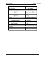
Input VSWR:
2.0:1
Input Impedance:
75 (50 Ω optional)
Mechanical Specifications:
Dimensions (W x L x H):
mBLC-1/2/5
mBLC-8
215.8 x 135.8 x 53.0 mm
215.8 x 135.8 x 61.5 mm
Weight (Kg):
mBLC-1/2/5
mBLC-8
1.9 kg
2.3 kg
Finish:
White polyurethane paint
Ambient Environmental Conditions:
Operating Temperature:
-40 to +60°C
Storage Temperature:
-55 to +85°C
Relative Humidity:
100%
Altitude:
Up to 3000 meter
Interface:
1-5
RF Output Connector:
CPR-137G
RF Input Connector:
F Type (option -N Type)
mBLC User Manual
Chapter 1: Introduction
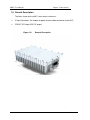
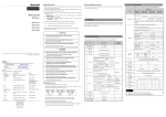
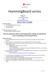
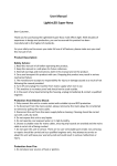
1.5 General Description
The items shown on the mBLC series outer surface are:
IF Input Connector: The modem or power inserter cable connection to the BUC.
CPR137 RF Output: BUC RF output.
Figure 1-2:
General Description
1-6
mBLC User Manual
2.
Chapter 2: Handling, Installation and Operation
Handling, Installation and Operation
This chapter provides instructions on how to handle and install the mBLC system
and includes the following sections:
Section 2.1: Handling
Section 2.1.6: Unpacking
Section 2.4: Installation and Operation
2.1
Handling
2.1.1
Transportation
The mBLC series BUC may be transported by land, air or sea while packed in
its original packaging.
2.1.2 Storage
While packed in its original package, the mBLC series BUC may be stored at
the following conditions:
Temperature Range: -55 to 85°C
Relative Humidity: up to 95% (non-condensing)
2.1.3 Return of Equipment
When returning equipment to Belcom Microwaves Ltd. for repair or
replacement:
1. Identify, in writing, the condition of the equipment.
2. Refer to the sales order, purchase order and the date the equipment was received.
Notify Belcom Microwaves Ltd. sales department of the equipment condition and obtain a
Return Material Authorization (RMA) number and shipping instructions. Consult Belcom
Microwaves Ltd. sales department for the best shipment method.
NOTE
Do not return any equipment without an RMA number. This is
important for prompt and efficient handling of the returned
equipment and of the associated complaint.
2-1
mBLC Manual
Chapter 2: Handling, Installation and Operation
2.1.4
Equipment Damage or Loss in Transit
Belcom Microwaves Ltd. is not responsible for damage or loss of equipment
during transit. In case of damage or loss of goods, contact the responsible
transport carrier.
When declaring equipment as damaged during transit preserve the original
shipping cartons to facilitate inspection reporting.
Belcom Microwaves Ltd. is responsible for damage or loss of equipment only if
the purchase order includes a "door-to-door" delivery (CIF by Incoterm).
Nevertheless, in any case of damage or loss of equipment, it is recommended
to contact Belcom Microwaves Ltd. which will make efforts to assist.
2.1.5 Receiving and Inspection
The mBLC will arrive in standard shipping containers. Immediately upon receipt
of the mBLC module, check the Bill of Lading against the actual equipment you
have received. Inspect the shipping containers exteriors for visible damage
incurred during shipping.
CATION
Handle the BUC with extreme care. Excessive shock may damage
the BUC's internal parts.
2-2
mBLC User Manual
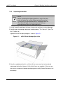
2.1.6
Chapter 2: Handling, Installation and Operation
Unpacking Instructions
NOTE
Before unpacking the shipping containers, move them near
to the site where the system will be mounted. Ensure that
the containers are oriented correctly in accordance with the
"This Side UP'' labels. Carefully remove the BUC and
packing material from the shipping containers..
1.Visually inspect the packages for traces of excessive moisture or external damage.
2.Carefully open the package, obeying all handling labels ("This Side Up", "Open This
End", Fragile, etc.).
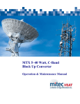
A general view of the open packages is shown in Figure 2-1:
Figure 2-1:
mBLC Series Package Open View
3.Using the supplied packing list, verify that all items were received and remained
undamaged during the shipment. Verify that all items are complete. If there are any
omissions or evidence of improper packaging, please notify Belcom Microwaves Ltd.
immediately.
2-3
mBLC Manual
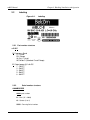
2.2
Chapter 2: Handling, Installation and Operation
Labeling
Figure 2-2:
Labeling
2.2.1 Part number structure
mBLX-P
X- Frequency Band
C- C Band
PA- Palapa
IN- Ext. C (Insat)
WC-Wide C (Standard C and Palapa)
P- Output power @ 1 db GC
1 - 1WATT
2 - 2WATT
3 - 3WATT
5 - 5WATT
8 - 8WATT
2.2.2
Serial number structure
AAAABQSSSS
AAAA- part number
B – Year (“9” = 2009)
Q – Quarter (1 to 4)
SSSS – Running Serial number.
2-4
mBLC User Manual
2.3
Chapter 2: Handling, Installation and Operation
Packing List
Verify that the following items are found in the package. In case of differences between
this list and the actual shipment part list, the shipment part list stands:
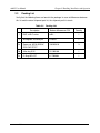
Table 2-1: Packing List
Description
Belcom Microwaves P/N
Quantity
1
BUC, mBLC series
mBL…
1
2
Waveguide Assembly kit
A10559
1
2a
Screw set, NF10-32X5/8",
SOC CAP ST.ST
106243610
9
2b
Allen key 5-32
511999100
1
2c
O-Ring WR-137
617999004
1
2-5
mBLC Manual
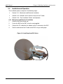
2.4
Chapter 2: Handling, Installation and Operation
Installation and Operation
The installation process comprises the following stages:
Section 2.4.1: Mechanical and Electrical Installation
Section 2.4.2: limitations on the total resistance of the IF cable
Section 2.4.3 : Post Installation Checks and Operation
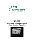
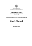
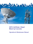
2.4.1 Mechanical and Electrical Installation
1.
Install the BUC with the ribs up.
2.
Fasten the BUC to the OMT using 8 screw(supplied).
3.
Connect the IFL cable from the modem to the IF connector in the BUC .
4.
Seal the connector of the IF cable to the BUC using a sealing tape.
Figure 2-3: Installing the mBLC Series
2-6
mBLC User Manual
Chapter 2: Handling, Installation and Operation
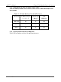
2.4.2 limitations on the total resistance of the IF cable
Note the following limitations on the total resistance of the IF cable connecting the BUC
to the modem.
Table 2-2: IF Cable Maximum Permitted Resistance
BUC model
DC Maximum Power
Consumption (W)
Minimum Input
Voltage to the
BUC (V)
Cable
Maximum.
Resistance (Ω)*
mBLC-1/2/3
24
15
5.6
mBLC-5
48
15
2.8
mBLC-8
55
15
2.4
* Sum of the center conductor and shield resistance
2.4.3 Post Installation Checks and Operation
Switch ON the Modem and check the uplink performance.
2-7
mBLC User Manual
3.
Chapter 3: Maintenance
Maintenance
3.1
Preventive Maintenance
The mBLC series does not require any preventive maintenance .
3.2
Troubleshooting
3.2.1 General
NOTE
In any case of a suspected unit, it is recommended to try a spare
unit, if available, in the same position and with the same cables,
in order to verify whether the fault is in the unit or in another part
of the system.
1. Make sure that the modem is turned on.
2. Make sure that the 10MHz reference signal in the modem is turned on.
3. Make sure that the total resistance of the cable is within the limits of table 2-2.
An easy way to test it is to connect the BUC to the modem using short a IFL cable
(less then 10m) if the BUC then functions properly, the resistance of the installation
cable is too high. Use a shorter cable or a cable with lower resistance.
3-1
mBLC Manual
Chapter 3: Maintenance
3.2.2 Detailed troubleshooting procedure
Problem / Suspicion: No output power
Possible cause: Missing power supply
Indications:
- System indicates no uplink signal.
- BUC surface temperature remains low after 15 minutes.
Further checks and remedy:
- Check the IFL cable connections.
- Check DC voltage at the IFL cable end (BUC side).
Problem / Suspicion: No output power
Possible cause: Internal temperature protection activated. (Excessive ambient
temperature might trigger the temperature protection.)
Indications:
- System indicates no uplink signal.
- BUC surface temperature hot.
Further checks and remedy:
- Let the unit cool down for 15 minutes.
- If possible, prevent direct sun radiation on the unit.
Problem / Suspicion: No output power
Possible cause: Wrong frequency sense setup in the modem
Indications:
- System indicates no uplink signal.
- Further checks and remedy:
- Check modem setup. Make sure modem is configured for positive frequency sense.
Problem / Suspicion: No output power
Possible cause: Missing or low 10 MHz reference
Indications:
- System indicates no uplink signal.
- BUC surface temperature remains low after 15 minutes.
Further checks and remedy:
Check modem setup. Make sure modem is configured to provide a reference signal.
3-2
mBLC User Manual
Chapter 3: Maintenance
Problem / Suspicion: No output power
Possible cause: Power supply low voltage
Indications:
- System indicates no uplink signal.
Further checks and remedy:
- Check the IFL cable specified DC resistance. (Use Belcom Microwaves cable
resistance application.)
- Check the IFL cable for breaks and proper connectors assembly.
Problem / Suspicion: No output power
Possible cause: Missing IF signal
Indications:
- System indicates no uplink signal.
Further checks and remedy:
- Check the IFL cable for breaks and proper connectors assembly.
- Check indoor equipment cable connections.
Problem / Suspicion: Low output power
Possible cause: Low IF input level
Indications:
- System indicates low uplink power
Further checks and remedy:
- Check the IFL cable for breaks and proper connectors assembly.
- Check the IFL cable specified attenuation. Assure proper IF level at the IF connector
(BUC side).
- Check modem output power setting.
- Check indoor equipment cable connections.
Problem / Suspicion: Spectral interference
Possible cause: Improper DC supply or neighbor equipment interference or Improper
modem signal
Indications:
- System or other equipment interfered by the transmission.
Further checks and remedy:
- Turn the unit off in order to isolate the interference. Make sure the right interferer is
located.
3-3