1
User’s
Manual
Model PR300
Power and Energy Meter
Communication Interface
(RS-485 and Ethernet Communications)
IM 77C01E01-10E
IM 77C01E01-10E
4th Edition
i
<Toc> <Ind> <Rev>
Introduction
This user's manual describes the communication functions of the PR300 power and energy
meter and contains information on how to create communication programs.
Hereafter, the PR300 power and energy meter is simply referred to as the PR300.
Read the manual carefully to understand the communication functions of the PR300 .
The PR300 has the following communication protocols.
●
PC link communication protocol
●
Modbus /RTU and Modbus/ASCII communication protocols
●
Modbus/TCP communication protocol (for the PR300 with Ethernet communication
function)
●
PR201 original communication protocol
You are required to have background knowledge of the communication specifications of
higher-level devices, their communication hardware, language used for creating communication programs, and so on.
■ Intended Readers
This manual is intended for people familiar with the functions of the PR300, control engineers and personnel in charge of maintaining instrumentation and control equipment.
■ Related Documents
The following user's manuals all relate to the communication functions of the PR300. Read
them as necessary.
● Model PR300 Power and Energy Meter User's Manual (electronic manual)
Document number: IM 77C01E01-01E
● Model PR300 Power and Energy Meter Startup Manual <Installation>
Document number: IM 77C01E01-02E
● Model PR300 Power and Energy Meter Startup Manual <Initial Setup Operations>
Document number: IM 77C01E01-03E
These manuals provide information about the procedure of installation, wiring and operation.
■ Trademark
(1) All the brands or names of Yokogawa Electric's products used in this manual are
either trademarks or registerd trademarks of Yokogawa Electric Corporation.
(2) Ethernet is a registered trademark of XEROX Corporation in the United States.
(3) Company and product names that appear in this manual are trademarks or registered
trademarks of their respective holders.
Media No. IM 77C01E01-10E
3rd Edition : Feb. 15, 2007 (YK)
All Rights Reserved Copyright © 2006, Yokogawa Electric Corporation
IM 77C01E01-10E
ii
<Toc> <Ind> <Rev>
Documentation Conventions
■ Symbols
This manual uses the following symbols.
● Symbols Used in the Main Text
NOTE
Draws attention to information that is essential for understanding the operation and/or
features of the product.
TIP
Gives additional information to complement the present topic.
See Also
Gives reference locations for further information on the topic.
● Symbols Used in Figures and Tables
[NOTE]
Draws attention to information that is essential for understanding the features of the
product.
[TIP]
Gives additional information to complement the present topic.
[See Also]
Gives reference locations for further information on the topic.
■ Description of Displays
(1) Some of the representations of product displays shown in this manual may be exaggerated, simplified, or partially omitted for reasons of convenience when explaining
them.
(2) Figures and illustrations representing the PR300's displays may differ from the real
displays in regard to the position and/or indicated characters (upper-case or lowercase, for example), the extent of difference does not impair a correct understanding of
the functions and the proper operations and monitoring of the system.
IM 77C01E01-10E
iii
<Toc> <Ind> <Rev>
Notices
■ Regarding This User's Manual
(1) This manual should be passed on to the end user. Keep the manual in a safe place.
(2) Read this manual carefully to gain a thorough understanding of how to operate this
product before you start using it.
(3) This manual is intended to describe the functions of this product. Yokogawa Electric
Corporation (hereinafter simply referred to as Yokogawa) does not guarantee that
these functions are suited to the particular purpose of the user.
(4) Under absolutely no circumstance may the contents of this manual, in part or in whole,
be transcribed or copied without permission.
(5) The contents of this manual are subject to change without prior notice.
(6) Every effort has been made to ensure accuracy in the preparation of this manual.
Should any errors or omissions come to your attention however, please contact your
nearest Yokogawa representative or our sales office.
(7) The document concerning TCP/IP software has been created by Yokogawa based on
the BSD Networking Software, Release 1 that has been licensed from the University
of California.
■ Regarding Protection, Safety, and Prohibition Against Unauthorized
Modification
(1) In order to protect the product and the system controlled by it against damage and
ensure its safe use, be certain to strictly adhere to all of the instructions and precautions relating to safety contained in this document. Yokogawa does not guarantee
safety if products are not handled according to these instructions.
(2) The following safety symbols are used on the product and/or in this manual.
● Symbols Used on the Product and in This Manual
This symbol on the product indicates that the operator must refer to an explanation in
the user's manual in order to avoid the risk of injury or death of personnel or damage
to the instrument. The manual describes how the operator should exercise special
care to avoid electric shock or other dangers that may result in injury or loss of life.
Protective Grounding Terminal
This symbol indicates that the terminal must be connected to ground prior to operating
the equipment.
IM 77C01E01-10E
iv
<Toc> <Ind> <Rev>
■ Force Majeure
(1) Yokogawa does not make any warranties regarding the product except those mentioned in the WARRANTY that is provided separately.
(2) Yokogawa assumes no liability to any party for any loss or damage, direct or indirect,
caused by the use or any unpredictable defect of the product.
(3) Be sure to use the spare parts approved by Yokogawa when replacing parts or
consumables.
(4) Modification of the product is strictly prohibited.
(5) Reverse engineering such as the disassembly or decompilation of software is strictly
prohibited.
(6) No portion of the software supplied by Yokogawa may be transferred, exchanged,
leased, or sublet for use by any third party without the prior permission of Yokogawa.
IM 77C01E01-10E
Toc-1
<Int> <Ind> <Rev>
Model PR300 Power and Energy Meter
Communication Interface
(RS-485 and Ethernet Communications)
IM 77C01E01-10E 4th Edition
CONTENTS
Introduction........................................................................................................... i
Documentation Conventions ...............................................................................ii
Notices .................................................................................................................iii
1.
2.
3.
Communications Overview
1.1
RS-485 Communication Specifications ......................................................... 1-1
1.2
Ethernet Communication Specifications ....................................................... 1-1
Setup
2.1
Setup Procedure .............................................................................................
2.1.1
Procedure for RS-485 Communication .............................................
2.1.2
Procedure for Ethernet Communication ............................................
2.1.3
Procedure for Ethernet-Serial Gateway Function ..............................
2-1
2-2
2-3
2-4
2.2
Setting Communication Conditions .............................................................. 2-6
2.2.1
Conditions for RS-485 Communication ............................................. 2-6
2.2.2
Conditions for Ethernet Communication ............................................ 2-8
2.2.3
Conditions for Ethernet-Serial Gateway Function ............................ 2-10
2.3
Wiring for Communication ........................................................................... 2-12
2.3.1
Wiring for RS-485 Communication .................................................. 2-12
2.3.2
Wiring for Ethernet Communication ................................................ 2-13
2.3.3
Wiring for RS-485 Communication for Ethernet-Serial Gateway Function .. 2-14
Procedures for Setting PR300 Functions
3.1
Basic Setting ...................................................................................................
3.1.1
Setting of VT Ratio ............................................................................
3.1.2
Setting of CT Ratio ............................................................................
3.1.3
Setting of Integrated Low-cut Power .................................................
3-2
3-2
3-3
3-4
3.2
Setting Pulse Output .......................................................................................
3.2.1
Selection of Measurement Item for Pulse Output ..............................
3.2.2
Pulse Unit .........................................................................................
3.2.3
ON Pulse Width ................................................................................
3-5
3-5
3-6
3-7
3.3
Setting Analog Output .................................................................................... 3-8
3.3.1
Selection of Measurement Item for Analog Output ............................ 3-8
3.3.2
Upper/Lower Limits of Scaling .......................................................... 3-9
3.4
Demand Setting ............................................................................................ 3-10
3.4.1
Demand Power/Current .................................................................. 3-10
3.4.2
Demand Period ................................................................................ 3-11
3.4.3
Demand Alarm Mask Time .............................................................. 3-12
3.4.4
Demand Power Alarm Point ............................................................ 3-13
IM 77C01E01-10E
Toc-2
<Int> <Ind> <Rev>
3.4.5
3.4.6
4.
Demand Current Alarm Point .......................................................... 3-14
Demand Alarm Release Function ................................................... 3-15
3.5
Communication Setting ................................................................................
3.5.1
Protocol ..........................................................................................
3.5.2
Baud Rate ......................................................................................
3.5.3
Parity ..............................................................................................
3.5.4
Stop Bit ...........................................................................................
3.5.5
Data Length ....................................................................................
3.5.6
Station Number ...............................................................................
3.5.7
IP Address (for Ethernet communication) ........................................
3.5.8
Subnet Mask (for Ethernet communication) ....................................
3.5.9
Default Gateway (for Ethernet communication) ...............................
3.5.10
Port Number (for Ethernet communication) .....................................
3-16
3-16
3-17
3-18
3-19
3-20
3-21
3-22
3-23
3-24
3-25
3.6
Writing Energy Values ..................................................................................
3.6.1
Active Energy .................................................................................
3.6.2
Regenerative Energy ......................................................................
3.6.3
LEAD Reactive Energy ...................................................................
3.6.4
LAG Reactive Energy .....................................................................
3.6.5
Apparent Energy .............................................................................
3-26
3-26
3-27
3-28
3-29
3-30
3.7
Executing Reset Operations ........................................................................
3.7.1
Remote Reset ................................................................................
3.7.2
Maximum/Minimum Values Reset ...................................................
3.7.3
Energy Value All-Reset ...................................................................
3.7.4
Active Energy Reset .......................................................................
3.7.5
Regenerative Energy Reset ............................................................
3.7.6
Reactive Energy Reset ...................................................................
3.7.7
Apparent Energy Reset ..................................................................
3-31
3-31
3-32
3-32
3-33
3-33
3-34
3-34
3.8
Setting Control States ..................................................................................
3.8.1
Integration Start/Stop .....................................................................
3.8.2
Optional Integration Start/Stop ........................................................
3.8.3
Demand Measurement Start/Stop ...................................................
3.8.4
Confirmation and Release of Demand Alarm State .........................
3-35
3-35
3-36
3-37
3-38
PC Link Communication Protocol
4.1
Overview .......................................................................................................... 4-1
4.1.1
Configuration of Command ............................................................... 4-2
4.1.2
Configuration of Response ............................................................... 4-3
4.1.3
Response Error Codes ..................................................................... 4-4
4.1.4
Specifying Broadcast ........................................................................ 4-5
4.2
Command and Response ............................................................................... 4-6
WRD Reads D registers on a word-by-word basis ................................... 4-7
WWR Writes data into D registers on a word-by-word basis ..................... 4-8
WRR Reads D registers on a word-by-word basis in random order ......... 4-9
WRW Writes data into D registers on a word-by-word basis in random order ... 4-10
WRS Specifies the D registers to be monitored on a word-by-word basis ........ 4-11
WRM Monitors the D registers on a word-by-word basis ........................ 4-12
INF6 Reads the model, suffix codes, and version information ............... 4-13
INF7 Reads the maximum value of CPU ............................................... 4-14
4.3
Communication with Higher-level Devices ................................................. 4-15
4.3.1
Communication with FA-M3 (UT Link Module) ................................ 4-15
IM 77C01E01-10E
Toc-3
<Int> <Ind> <Rev>
4.4
5.
6.
7.
8.
Sample Program ........................................................................................... 4-17
4.4.1
Example of BASIC Program for Send and Receive ......................... 4-17
Modbus/RTU and ASCII Communication Protocols
5.1
Overview .......................................................................................................... 5-1
5.1.1
Configuration of Message ................................................................. 5-3
5.1.2
Specifying D Registers...................................................................... 5-4
5.1.3
Checking Errors ................................................................................ 5-4
5.1.4
Configuration of Response ............................................................... 5-7
5.1.5
Specifying Broadcast ........................................................................ 5-9
5.2
Message and Response ............................................................................... 5-10
03
Reads data from multiple D registers ............................................ 5-11
06
Writes data into D register ............................................................. 5-12
08
Performs loop back test ................................................................. 5-13
16
Writes data into multiple D registers .............................................. 5-14
Modbus/TCP Communication Protocol
6.1
Overview .......................................................................................................... 6-1
6.2
TCP/IP Communication .................................................................................. 6-3
6.3
Network Frame Structure ............................................................................... 6-4
6.3.1
MBAP Header Structure ................................................................... 6-4
6.3.2
PDU Structure .................................................................................. 6-4
6.4
Communication with Higher-level Devices ................................................... 6-5
6.4.1
List of Function Codes ...................................................................... 6-5
6.4.2
Specifying D Registers...................................................................... 6-5
6.4.3
Request and Response .................................................................... 6-6
03
Reads data from multiple D registers .............................................. 6-6
06
Writes data into D register ............................................................... 6-7
08
Performs loop back test ................................................................... 6-8
16
Writes data into multiple D registers ................................................ 6-9
6.4.4
Response Error Codes .................................................................... 6-11
6.5
Sample Program ........................................................................................... 6-12
6.5.1
Example of BASIC Program for Send and Receive ......................... 6-12
Functions and Usage of D Registers
7.1
Overview of D Registers ................................................................................. 7-1
7.2
Configuration of D Registers .......................................................................... 7-1
7.3
Interpretation of D Register Map Table .......................................................... 7-1
7.4
D Register Map ................................................................................................ 7-2
PR201 Original Communication Protocol
8.1
Overview .......................................................................................................... 8-1
8.2
Communication Specifications ...................................................................... 8-1
8.3
Command/Response Format ......................................................................... 8-2
8.4
List of Commands ........................................................................................... 8-3
8.5
Command Details............................................................................................ 8-5
Appendix
Table of ASCII Codes (Alphanumeric Codes)
Revision Information
IM 77C01E01-10E
<Toc> <Ind>
<1. Communications Overview >
1.
Communications Overview
1.1
RS-485 Communication Specifications
1-1
Protocols available for RS-485 communication interfaces include the PC link communication protocol and the Modbus communication protocol.
Table 1.1 RS-485 Communication Specifications
Item
Details
Communication Hardware
2-wire system RS-485
Compliant Standard
Protocol Specification
EIA RS-485
PC Link Communication with
and without checksum
Modbus Communication
(ASCII and RTU modes)
PR201 original communication
Baud Rate
Maximum Communication Distance
Maximum Number of
Connectable Devices
Transmission Method
Synchronization
Communication Method
Communication Cable
1.2
Connected Device
A PC installed with a driver for PC link
communication and SCADA software,
PLC (FA-M3 UT link module), etc.
A PC installed with a Modbus driver
and SCADA software,
a Modbus-compatible PLC, etc.
Personal computer etc. with SCADA
software installed to support PR201
original communication protocol
2400 bps, 9600 bps, 19200 bps
1200 m
31
2-wire, half-duplex
Start-stop synchronization
Non-procedural
Shielded twisted pair cable
(AWG24-equivalent size)
Ethernet Communication Specifications
Protocols available for Ethernet communication interfaces include the Modbus/TCP
communication protocol.
Table 1.2 Ethernet Communication Specifications
Item
Communication Hardware
Compliant Standard
Access Control
Protocol Specification
Baud Rate
Maximum Segment Length
Maximum Connecting
Configuration
Communication System
Data Format
Maximum Number of
Connections
Details
10BASE-T/100BASE-TX
Ethernet IEEE802.3
CSMA/CD
Modbus communication (Port No.: 502)
10 Mbps/100 Mbps
100 m *1
Cascade max. 4 levels (for 10BASE-T)
max. 2 levels (for 100BASE-TX) *2
TCP/IP
Binary
1
Connected Device
Ethernet-equipped PC etc.
*1: Distance between the hub and module.
*2: The number of hubs connectable in cascade configuration.
IM 77C01E01-10E
<Toc> <Ind>
2.
<2. Setup>
2-1
Setup
This chapter describes how to set up the PR300, which is equipped with RS-485
communication as a standard feature.
When using an Ethernet-equipped model, either RS-485 or Ethernet can be selected
by parameter setting for communications.
For details of use of RS-485 communication, see subsection 2.1.1 “Procedure for
RS-485 Communication.”
For details of use of the Ethernet communication, see subsection 2.1.2 “Procedure
for Ethernet Communication.”
For details of use of the Ethernet-serial gateway function, see subsection 2.1.3
“Procedure for Ethernet-Serial Gateway Function.”
2.1
Setup Procedure
Set up the communication functions on the PR300 as follows:
WARNING
To avoid an electric shock, be sure to turn off the power supply source to the equipment
involved before you start wiring.
Note: Create communication programs referring to the user’s manual for communications of each higher-level device.
Higher-level devices : PCs, PLCs (sequencers), and others.
IM 77C01E01-10E
<Toc> <Ind>
2.1.1
<2. Setup>
Procedure for RS-485 Communication
(Example)
Higher-level device
Maximum communication distance: 1200 m
Maximum number of slave stations to be connected: 31
Station number 01
(arbitrary)
1
Station number 02
(arbitrary)
Station number 10
(arbitrary)
Station number 20
(arbitrary)
Communication parameters setting for PR300
Set up the communication function using
the front panel keys.
See
Subsection 2.2.1 “Conditions for RS-485
Communication”
2
Connect a higher-level device with PR300
See
Subsection 2.3.1
“Wiring for RS-485 Communication”
3
Create communication programs for the
higher-level device to perform
communication
See
Chapter 3
“Procedures for Setting PR300 Functions”
For communication protocol, see
Chapter 4
“PC Link Communication Protocol”
Chapter 5
“Modbus/RTU and ASCII Communication Protocols”
Chapter 8
“PR201 Original Communication Protocol”
For data storage location, see
Chapter 7
“Functions and Usage of D Registers”
IM 77C01E01-10E
2-2
<Toc> <Ind>
2.1.2
<2. Setup>
Procedure for Ethernet Communication
(Example)
Higher-level device
IP address [192.168.1.1]
(arbitrary)
HUB
Ethernet
Maximum distance between hub and module: 100 m
Maximum number of hubs connectable in cascade configuration:
4 levels for 10BASE-T
2 levels for 100BASE-TX
LAN
connection
Station number 01 (fixed)
IP address [192.168.1.2]
(arbitrary)
1
Station number 01 (fixed)
IP address [192.168.1.3]
(arbitrary)
Station number 01 (fixed)
IP address [192.168.1.4]
(arbitrary)
Station number 01 (fixed)
IP address [192.168.1.5]
(arbitrary)
Communication parameters setting for PR300
Set up the communication function using
the front panel keys.
See
Subsection 2.2.2 “Conditions for Ethernet
Communication”
2
Connect a higher-level device with PR300
See
Subsection 2.3.2
“Wiring for Ethernet Communication”
3
Create communication programs for the
higher-level device to perform
communication
See
Chapter 3
“Procedures for Setting PR300 Functions”
For communication protocol, see
Chapter 6
“Modbus/TCP Communication Protocol”
For data storage location, see
Chapter 7
“Functions and Usage of D Registers”
Note: It is recommended to use the Ethernet network as a dedicated one for the
PR300.
IM 77C01E01-10E
2-3
<Toc> <Ind>
2.1.3
<2. Setup>
Procedure for Ethernet-Serial Gateway Function
(Example)
Higher-level device
IP address [192.168.1.1] (arbitrary)
Ethernet
PR300
(with Ethernet
communication function)
Station number 01 (fixed)
IP address [192.168.1.2] (arbitrary)
RS-485
Station number 02
(arbitrary)
1
Station number 03
(arbitrary)
Station number 20
(arbitrary)
Communication parameters setting for PR300
Set up the communication function using
the front panel keys.
See
Subsection 2.2.2
“Conditions for Ethernet Communication”
Subsection 2.2.3
“Conditions for Ethernet-Serial Gateway Function”
2
Connect a higher-level device with PR300
See
Subsection 2.3.2
“Wiring for Ethernet Communication”
3
Connect a lower-level device with PR300
See
Subsection 2.3.3
“Wiring for RS-485 Communication for
Ethernet-Serial Gateway Function”
4
Create communication programs for the
higher-level device to perform
communication
See
Chapter 3
“Procedures for Setting PR300 Functions”
For communication protocol, see
Chapter 6
“Modbus/TCP Communication Protocol”
For data storage location, see
Chapter 7
“Functions and Usage of D Registers”
Note: It is recommended to use the Ethernet network as a dedicated one for the PR300.
IM 77C01E01-10E
2-4
<Toc> <Ind>
<2. Setup>
2-5
● VJET Ethernet/RS-485 converter as an Ethernet-serial gateway function
(Example)
Higher-level device
IP address [192.168.1.1] (arbitrary)
Ethernet
VJET*
Ethernet/RS-485 converter
Station number 01 (fixed)
IP address [192.168.1.2] (arbitrary)
RS-485
Station number 02 (arbitrary)
Station number 03 (arbitrary)
Station number 20 (arbitrary)
* The VJET is Yokogawa’s converter. For details of use of the VJET, refer to its user’s manual.
Note: It is recommended to use the Ethernet network as a dedicated one for the PR300.
The communication conditions of any slave PR300 must conform to those of the VJET at
a higher level.
IM 77C01E01-10E
<Toc> <Ind>
2.2
2-6
<2. Setup>
Setting Communication Conditions
This section describes the setting parameters for using the communication functions, and the setting ranges. For details of setting method, refer to the PR300
Power and Energy Meter User’s Manual (electronic manual).
2.2.1
Conditions for RS-485 Communication
This subsection describes the setting parameters for using the RS-485 communication
function, and the setting ranges.
Table 2.1 Parameters to be Set for Communication Functions
Parameter Name
Menu
Parameter Symbol
Initial
Value
Setting Range
01 to 99 (01 to 31 recommended)
Station number
01
(ST-NO)
PC link without checksum
PC link with checksum
Modbus/ASCII
Modbus/RTU
(M TCP)
PR201 original
(RS-485
communication)
(B-RT)
(PR201)
2400 bps
9600 bps
19200 bps
9600
None
(PRI)
Odd
NONE
(ODD)
1
(STP)
2
7
Data length*2 *3
8
(DLN)
*3:
(EVEN)
1
Stop bit*3
*1:
*2:
(NONE)
Even
Parity*3
PCLK2
(M RTU)
Modbus/TCP*1
Baud rate
(PCLK2)
(M ASC)
Protocol
(COMM)
(PCLK1)
8
Modbus/TCP can be selected for the PR300 with Ethernet communication function only.
When Modbus /RTU is selected for the protocol, select 8 for the data length. If 7 is selected for the data length,
communication is not possible.
When PR201 original is selected for the protocol, select NONE for the parity, 1 for the stop bit and 8 for the data length.
IM 77C01E01-10E
<Toc> <Ind>
<2. Setup>
2-7
● Protocol (COMM)
Set the communication protocol identical to that of the higher-level device to be connected.
● Station number (ST-NO)
Set the station number of the PR300 itself. A station number of 01 to 99 may be assigned
in any order. However, the maximum number of PR300 to be connected to a single communication port is 31.
When connecting two or more PR300 to a single communication port, set a different station
number to each.
Example of connecting a higher-level device with four PR300 having station numbers 01,
05, 10, and 20
(Example)
Higher-level device
Maximum communication distance: 1200 m
Maximum number of slave sations to be connected: 31
Station number 01
(arbitrary)
Station number 05
(arbitrary)
Station number 10
(arbitrary)
Station number 20
(arbitrary)
● Baud rate (B-RT)
Set the baud rate identical to that of the higher-level device to be connected. (Otherwise,
proper communication cannot be achieved.)
● Parity (PRI)
Set the handling of parity to be carried out when data is sent or received. Set the parity bit
state identical to that of the higher-level device to be connected.
* When PR201 original is selected for the protocol, select NONE for the parity.
● Stop bit (STP)
Set the stop bit identical to that of the higher-level device to be connected.
* When PR201 original is selected for the protocol, select 1 for the stop bit.
● Data length (DLN)
Set the same data length as for the upper device that is to be connected.
* When Modbus/RTU is selected for the protocol, select 8 for the data length.
* When PR201 original is selected for the protocol, select 8 for the data length.
IM 77C01E01-10E
<Toc> <Ind>
2.2.2
<2. Setup>
2-8
Conditions for Ethernet Communication
This subsection describes the setting parameters for using the Ethernet communication
function, and the setting ranges.
Table 2.2 Parameters to be Set for Communication Functions
Parameter Name
Menu
Parameter Symbol
PC link without checksum
PC link with checksum
Modbus/ASCII
(COMM)
(PCLK1)
(PCLK2)
(M ASC)
Protocol
(RS-485
Communication)
Initial
Value
Setting Range
Modbus/RTU
PCLK2
(M RTU)
1
Modbus/TCP*
(M TCP)
PR201 original
IP address-1
(PR201)
0 to 255
192
0 to 255
168
0 to 255
1
0 to 255
1
0 to 255
255
0 to 255
255
0 to 255
255
0 to 255
0
0 to 255
0
0 to 255
0
0 to 255
0
0 to 255
0
(IP-1)
IP address-2
(IP-2)
IP address-3
(IP-3)
IP address-4
(IP-4)
Subnet mask-1
(SM-1)
Subnet mask-2
(SM-2)
Subnet mask-3
(SM-3)
Subnet mask-4
(Ethernet
Communication)
*2
(SM-4)
Default gateway-1
(DG-1)
Default gateway-2
(DG-2)
Default gateway-3
(DG-3)
Default gateway-4
(DG-4)
502, 1024 to 65535
Port number
(PORT)
OFF, ON
Ethernet setting switch
(E-SW)
*1:
*2:
Modbus/TCP can be selected for the PR300 with Ethernet communication function only.
Ethernet communication menu is displayed when Modbus/TCP is selected for the protocol.
IM 77C01E01-10E
502
<Toc> <Ind>
<2. Setup>
2-9
● Protocol (COMM)
Set the protocol to Modbus/TCP.
● IP address-1 to 4 (IP-n) [n: integers from 1 to 4]
Set the IP address for the PR300 by the following format.
0 to 255
IP address
IP-1
0 to 255
IP-2
0 to 255
IP-3
0 to 255
IP-4
● Subnet mask-1 to 4 (SM-n) [n: integers from 1 to 4]
Set the subnet mask for the PR300 by the following format.
Subnet Mask
0 to 255
0 to 255
0 to 255
0 to 255
SM-1
SM-2
SM-3
SM-4
● Default gateway-1 to 4 (DG-n) [n: integers from 1 to 4]
Set the default gateway for the PR300 by the following format.
Default Gateway
0 to 255
0 to 255
0 to 255
0 to 255
DG-1
DG-2
DG-3
DG-4
NOTE
Before performing setup of IP address, subnet mask, and default gateway, consult the
administrator for the network to which the PR300 is to be connected.
● Port number (PORT)
Set the port number for the PR300.
NOTE
To activate the settings of IP address, subnet mask, default gateway, and port number, set
the Ethernet setting switch to ‘ON’ after setting them.
● Ethernet setting swtich (E-SW)
This switch activates the Ethernet communication parameters settings. Setting this parameter to ON activates the settings of IP address, subnet mask, default gateway, and port
number.
This parameter automatically reverts to OFF in about 20 seconds after being set to ON.
IM 77C01E01-10E
<Toc> <Ind>
2.2.3
<2. Setup>
2-10
Conditions for Ethernet-Serial Gateway Function
The Ethernet-serial gateway function is a function that reads/writes data from/to other
devices equipped with RS-485 serial communication function using the Modbus/TCP
protocol via the PR300.
With this function, the higher-level device can access the devices connected to the RS-485
serial communication line in the same way as to access the devices connected to Ethernet.
(Example)
Higher-level device
Ethernet
10BASE-T, 100BASE-TX
PR300
(with Ethernet
communication function)
Station number 01 (fixed)
RS-485
Device with RS-485 serial
communication function
Power Monitor of POWERCERT series
Digital indicating controller of
GREEN series
Signal conditioner of JUXTA series
Station number 02
(arbitrary)
Station number 03
(arbitrary)
Station number 04
(arbitrary)
The PR300 operates as a gateway that changes the Modbus/TCP protocol received via
network to the Modbus/RTU protocol for the serial devices connected to the RS-485
communication interface. Therefore, the devices supporting the Modbus/RTU protocol are
required for the devices to be connected.
NOTE
• If the Ethernet-serial gateway function is used, set a station number other than 01 for
the RS-485 communication devices which are slaves of the PR300 connected to
Ethernet.
• If the Ethernet communication function is used, the RS-485 communication interface
is used specifically for the Ethernet-serial gateway function. Therefore, it is not possible for a higher-level device such as a PC to access the PR300 via the RS-485
communication interface.
IM 77C01E01-10E
<Toc> <Ind>
2-11
<2. Setup>
● Setting for PR300 to perform the Ethernet-serial gateway function
To use the Ethernet-serial gateway function, set the parameters of subsection 2.2.2, “Conditions for Ethernet Communication” and set a parity (PRI) in Table 2.3.
When the protocol is set to Modbus/TCP, the parameters of RS-485 other than the parity
are fixed and unchangeable.
Table 2.3 Parameters of PR300 to Perform the Ethernet-Serial Gateway Function
Parameter Name
Menu
Parameter Symbol
Station number
Initial
Value
Setting Range
01
01 (fixed)
(ST-NO)
Baud rate
9600
9600 bps (fixed)
(B-RT)
Parity
Stop bit
(PRI)
(RS-485
communication)
None
Even
Odd
NONE
EVEN
ODD
NONE
1 (fixed)
1
8 (fixed)
8
(STP)
Data length
(DLN)
● Slave PR300
The station number of any slave PR300 (device for RS-485 communication) must be a
different number other than 01.
The communication conditions for any slave PR300 (device for RS-485 communication)
other than the station number must conform to those in Table 2.3.
Table 2.4 Parameters of Slave PR300
Parameter Name
Menu
Parameter Symbol
Initial
Value
Setting Range
01
02 to 99
Station number
(ST-NO)
Baud rate
(B-RT)
2400 bps
9600 bps
19200 bps
9600
NONE
EVEN
ODD
None
Parity
(RS-485
communication)
(PRI)
Even
Odd
NONE
1
1
Stop bit
(STP)
2
7
Data length
8
(DLN)
8
When using the VJET Ethernet/RS-485 converter as an Ethernet-serial gateway function,
the communication conditions of any slave PR300 must conform to those of the VJET at a
higher level. The initial value of the VJET parity is EVEN.
IM 77C01E01-10E
<Toc> <Ind>
2.3
2-12
<2. Setup>
Wiring for Communication
Connect a higher-level device with the PR300 for using the communication functions. The wiring procedures and precautionary notes are as follows.
2.3.1
Wiring for RS-485 Communication
For a common PC, the RS-485 interface is not directly connectable. Use a ML2 RS232C/
RS485 converter for wiring.
WARNING
To avoid an electric shock, be sure to turn off the power supply source to the equipment
involved before you start wiring.
Use crimp-on terminals at cable ends.
Before you start wiring, read the user’s manual of each device.
PR300
(with RS-485
communication function)
PR300
(with RS-485
communication function)
(RS232C/RS485 converter)
Terminator
120Ω 1/4W
PC
3
4
5
RS-232C
straight cable
6
Aⴚ
Bⴙ
SG
Communication cable
JIS Class D (3) grounding
(grounding resistance
of 100Ω or less)
17
18
19
20
Aⴚ
Bⴙ
SG
18
19
Terminator (built-in)
120Ω 1/4W
Wthen terminating on
wiring, short-circuit
terminals 17 and 18 .
20
Communication cable
JIS Class D (3) grounding
(grounding resistance
of 100Ω or less)
Note: Use UL Listed RS-232C/RS-485 converter if the converter has AC/DC power supply input; this is
optional for converters supplied by a Limited Power Source with input voltages less than 30 V AC or
60 V DC and which are separated from mains by double or reinforced insulation.
Communication cable: Shielded twisted pair cable (AWG24-eqivalent size)
Recommended terminals: See the PR300 Power and Energy Meter User’s Manual (electronic manual).
IM 77C01E01-10E
<Toc> <Ind>
2.3.2
<2. Setup>
2-13
Wiring for Ethernet Communication
To use the Ethernet communication function, connect a higher-level device with the PR300
with Ethernet communication function using 10BASE-T/100BASE-TX. 10BASE-T/
100BASE-TX are Ethernet connection methods using twisted pair cables. The transmission
rates are 10 Mbps/100 Mbps. In 10BASE-T/100BASE-TX networks, higher-level devices
such as a PC are connected in a star pattern through a hub.
WARNING
To avoid an electric shock, be sure to turn off the power supply source to the equipment
involved before you start wiring.
Use hubs and twisted pair cables that conforms to the Ethernet specifications. The maximum number of hubs connectable in cascade configuration is 4 for 10ABSE-T and 2 for
100BASE-TX. The maximum allowable length of twisted pair cables is 100 meters.
Read the user’s manual of each device carefully before wiring.
* Devices that can be connected to Ethernet
PC
Data transmission
and reception
HUB
Ethernet
PR300 with
Ethernet
communication
function
Ethernet Port of PR300
The PR300 can detect 10BASE-T or
100BASE-TX automatically. The LEDs of
Ethernet port show its status.
Link LED (upper side)
Color
Meaning
Off
No Link
Amber
10 Mbps
Green
100 Mbps
Activity LED (lower side)
Color
Meaning
Off
No Activity
Amber
Half-duplex
Green
Full-duplex
IM 77C01E01-10E
<Toc> <Ind>
2.3.3
2-14
<2. Setup>
Wiring for RS-485 Communication for Ethernet-Serial
Gateway Function
To use the Ethernet-serial gateway function, connect other RS-485 serial communication
device to the RS-485 communication terminals .
WARNING
To avoid an electric shock, be sure to turn off the power supply source to the equipment
involved before you start wiring.
The figure below shows the example of wiring connection for the PR300 with Ethernet
communication function. If other devices are used for connection, the names of communication terminals and others may be different from those mentioned in the figure.
Read the user’s manual of each device carefully before wiring.
PC
Ethernet
PR300
(with Ethernet
communication function)
PR300
(with RS-485
communication function)
17
Terminator (built-in)
120Ω 1/4W
Wthen terminating on
wiring, short-circuit
terminals 17 and 18 .
18
19
20
PR300
(with RS-485
communication function)
Aⴚ
17
Aⴚ
18
Bⴙ
Bⴙ
19
SG
SG
20
Communication
cable
Communication
cable
JIS Class D (3) grounding
(grounding resistance
of 100Ω or less)
IM 77C01E01-10E
18
19
20
Terminator (built-in)
120Ω 1/4W
Wthen terminating on
wiring, short-circuit
terminals 17 and 18 .
<Toc> <Ind>
3.
<3. Procedures for Setting PR300 Functions>
3-1
Procedures for Setting PR300 Functions
To set the functions of the PR300, use the protocols described in Chapter 4, “PC
Link Communication Protocol,” Chapter 5, “Modobus/RTU and ASCII Communication Protocols,” or Chapter 6, “Modbus/TCP Communication Protocol” according to
the instructions in this chapter.
For details of each function, refer to the PR300 Power and Energy Meter User’s
Manual (electronic manual).
For how to read the tables in this chapter, refer to Chapter 7, “Functions and Usage
of D Registers.”
The PR300 offers registers for floating-point data. To perform settings via communication from higher-level device, floating-point data is displayed by IEEE754 (single
precision).
NOTE
• The PR300 has data (D register) the unit of which is two words. When 2-word data
need to be written or read, writing or reading operations must be performed for the 2word data at the same time.
• Even if data written to the D register is out of the effective range, a normal response is
returned. The part of the written data within the effective range becomes effective on
the PR300 when the equivalent setting change status is written for that data.
IM 77C01E01-10E
<Toc> <Ind>
<3. Procedures for Setting PR300 Functions>
3.1
Basic Setting
3.1.1
Setting of VT Ratio
3-2
[Procedure]
(1) Write a VT ratio to the two D registers in the table below. The data type is 4-byte
floating point.
(2) After writing that value, write 1 to the setup change status register, D0207.
D Register
Reference No.
H No.
Effective Range
Description
D0201
40201
00C8
VT ratio (float, lower 2 bytes)
D0202
40202
00C9
VT ratio (float, upper 2 bytes)
D0207
40207
00CE
Setup change status
If other than 1: Invalid
(D0201 to D0206 are validated) If 1: Writing is executed
1 to 6000
Initial value of VT ratio: 1 (4-byte floating-point data: 3F800000)
[Example]
To set the VT ratio to 10:
For station number 01, use PC link communication (without checksum) and the random
write command as shown below:
If 10 is converted into a 4-byte floating-point value, the value is 4120 0000.
[Command]
[STX] 01010WRW03D0201, 0000, D0202, 4120, D0207, 0001 [ETX] [CR]
[Response]
[STX] 0101OK [ETX] [CR]
NOTE
• When changing the VT ratio, the integrated values of active energy, reactive energy,
apparent energy, optional active energy, and regenerative energy will return to “0.”
The values of the demand alarm point and the scaling of analog output will also be
initialized.
• Set the VT and CT ratios so that [secondary rated power] × [VT ratio] × [CT ratio] is
smaller than 10 GW. When this value is 10 GW or greater, writing to D registers will be
invalid (no error is output).
IM 77C01E01-10E
<Toc> <Ind>
3.1.2
<3. Procedures for Setting PR300 Functions>
3-3
Setting of CT Ratio
[Procedure]
(1) Write a CT ratio to the two D registers in the table below. The data type is 4-byte
floating point.
(2) After writing that value, write 1 to the setup change status register, D0207.
D Register
Reference No.
H No.
Effective Range
Description
D0203
40203
00CA
CT ratio (float, lower 2 bytes)
D0204
40204
00CB
CT ratio (float, upper 2 bytes)
D0207
40207
00CE
Setup change status
If other than 1: Invalid
(D0201 to D0206 are validated) If 1: Writing is executed
0.05 to 32000
Initial value of CT ratio: 1 (4-byte floating-point data: 3F800000)
[Example]
To set the CT ratio to 10.0:
For station number 01, use PC link communication (without checksum) and the random
write command as shown below:
If 10.0 is converted into a 4-byte floating-point value, the value is 4120 0000.
[Command]
[STX] 01010WRW03D0203, 0000, D0204, 4120, D0207, 0001 [ETX] [CR]
[Response]
[STX] 0101OK [ETX] [CR]
NOTE
• When changing the CT ratio, the integrated values of active energy, reactive energy,
apparent energy, optional active energy, and regenerative energy will return to “0.”
The values of the demand alarm point and the scaling of analog output will also be
initialized.
• Set the VT and CT ratios so that [secondary rated power] × [VT ratio] × [CT ratio] is
smaller than 10 GW. When this value is 10 GW or greater, writing to D registers will be
invalid (no error is output).
IM 77C01E01-10E
<Toc> <Ind>
3.1.3
<3. Procedures for Setting PR300 Functions>
3-4
Setting of Integrated Low-cut Power
[Procedure]
(1) Write an integrated low-cut power value to the two D registers in the table below. The
data type is 4-byte floating point.
(2) After writing that value, write 1 to the setup change status register, D0207.
D Register
D0205
Reference No.
40205
H No.
Description
00CC
Integrated low-cut power
(float, lower 2 bytes)
Effective Range
0.05 to 20.00
Unit: %
D0206
40206
00CD
Integrated low-cut power
(float, upper 2 bytes)
D0207
40207
00CE
If other than 1: Invalid
Setup change status
(D0201 to D0206 are validated) If 1: Writing is executed
Initial value of integrated low-cut power: 0.05% (4-byte floating-point data: 3D4CCCCD)
[Example]
To set the integrated low-cut power value to 10.0%:
For station number 01, use PC link communication (without checksum) and the random
write command as shown below:
If 10.0 is converted into a 4-byte floating-point value, the value is 4120 0000.
[Command]
[STX] 01010WRW03D0205, 0000, D0206, 4120, D0207, 0001 [ETX] [CR]
[Response]
[STX] 0101OK [ETX] [CR]
IM 77C01E01-10E
<Toc> <Ind>
<3. Procedures for Setting PR300 Functions>
3.2
Setting Pulse Output
3.2.1
Selection of Measurement Item for Pulse Output
3-5
[Procedure]
(1) Write a measurement item for pulse output value to the D register in the table below.
The data type is integer.
(2) After writing that value, write 1 to the pulse output writing status register, D0211.
D Register
Reference No.
H No.
Description
D0208
40208
00CF
Measurement item for
pulse output
D0211
40211
00D2
Pulse output writing status
(D0208, D0209, and D0210
are validated)
Effective Range
0: Active energy
1: Regenerative energy
2: LEAD reactive energy
3: LAG reactive energy
4: Apparent energy
If other than 1: Invalid
If 1: Writing is executed
Initial value of measurement item for pulse output: 0 (active energy)
[Example]
To set the measurement item for pulse output to 1 (LEAD reactive energy):
For station number 01, use PC link communication (without checksum) and the random
write command as shown below:
[Command]
[STX] 01010WRW02D0208, 0001, D0211, 0001 [ETX] [CR]
[Response]
[STX] 0101OK [ETX] [CR]
NOTE
• A measurement item for pulse output value can be set for the PR300 with pulse
output.
• When the PR300 is the three-phase four-wire system (2.5 element), the following
measurement items can be measured only when the current is in a state of equilibrium:
“2: LEAD reactive energy”, “3: LAG reactive energy” and “4: Apparent energy.”
IM 77C01E01-10E
<Toc> <Ind>
3.2.2
<3. Procedures for Setting PR300 Functions>
3-6
Pulse Unit
[Procedure]
(1) Write a pulse unit value to the D register in the table below. The data type is integer.
(2) After writing that value, write 1 to the pulse output writing status register, D0211.
D Register
Reference No.
H No.
Effective Range
Description
D0209
40209
00D0
Pulse unit
1 to 50,000
Unit: 100 Wh/pulse
D0211
40211
00D2
Pulse output writing status
(D0208, D0209, and D0210
are validated)
If other than 1: Invalid
If 1: Writing is executed
Initial value of pulse unit: 10 (1000 Wh/pulse)
[Example]
To set the pulse unit to 100 Wh/pulse, write “0001.”
For station number 01, use PC link communication (without checksum) and the random
write command as shown below:
[Command]
[STX]01010WRW02D0209,0001,D0211,0001[ETX][CR]
[Response]
[STX]0101OK[ETX][CR]
NOTE
• A pulse unit value can be set for the PR300 with pulse output.
• To set the pulse unit value via communication, set it to 1/100 the value of the displayed
(true) value (e.g., set it to 5 when setting the pulse unit value to 500 Wh/pulse).
IM 77C01E01-10E
<Toc> <Ind>
3.2.3
<3. Procedures for Setting PR300 Functions>
3-7
ON Pulse Width
(1) Write an ON pulse width value to the D register in the table below. The data type is
integer.
(2) After writing that value, write 1 to the pulse output writing status register, D0211.
NOTE
When the value to be set for the ON pulse width is greater than the value calculated by the
following equation, the value cannot be set:
ON pulse width (ms) D Register
Pulse unit [Wh/pls] 60 60 1000
Secondary rated power [W] VT ratio CT ratio 1.2 2
Reference No.
H No.
Description
Effective Range
D0210
40210
00D1
ON pulse width
1 to 127
Unit: 10 ms
D0211
40211
00D2
Pulse output writing status
(D0208, D0209, and D0210
are validated)
If other than 1: Invalid
If 1: Writing is executed
Initial value of ON pulse width: 5 (50 ms)
[Example]
To set the ON pulse width to 100 ms, write “000A.”
For station number 01, use PC link communication (without checksum) and the random
write command as shown below:
[Command]
[STX] 01010WRW02D0210, 000A, D0211, 0001 [ETX] [CR]
[Response]
[STX] 0101OK [ETX] [CR]
NOTE
• An ON pulse width value can be set for the PR300 with pulse output.
• To set the ON pulse width value via communication, set it to 1/10 the value of the
displayed (true) value (e.g., set it to 5 when setting the ON pulse width value to 50
ms).
IM 77C01E01-10E
<Toc> <Ind>
<3. Procedures for Setting PR300 Functions>
3.3
Setting Analog Output
3.3.1
Selection of Measurement Item for Analog Output
3-8
[Procedure]
(1) Write a measurement item for analog output value to the D register in the table below.
The data type is integer.
(2) After writing that value, write 1 to the analog output writing status register, D0217.
D Register
Reference No.
H No.
Description
Effective Range
D0212
40212
00D3
Measurement item for
analog output
0: Active power
1: Reactive power
2: Apparent power
3: Voltage-1
4: Voltage-2
5: Voltage-3
6: Current-1
7: Current-2
8: Current-3
9: Power factor
10: Frequency
D0217
40217
00D8
Analog output writing status
(D0212 to D0216 are
validated)
If other than 1: Invalid
If 1: Writing is executed
Initial value of measurement item for analog output: 0 (active power)
[Example]
To set the measurement item for analog output to 3 (voltage-1):
For station number 01, use PC link communication (without checksum) and the random
write command as shown below:
[Command]
[STX] 01010WRW02D0212, 0003, D0217, 0001 [ETX] [CR]
[Response]
[STX] 0101OK [ETX] [CR]
NOTE
• A measurement item for analog output value can be set for the PR300 with analog
output.
• Different types of the PR300 can measure different items, and so the values that can
be set to the D register differ depending on the PR300 type. If a value that cannot be
written to the D register is written, it will be invalid. The table below shows the values
that cannot be set for four types of the PR300:
Phase and Wire System
Single-phase two-wire
Single-phase three-wire
Three-phase three-wire
Three-phase four-wire (2.5 element)
Values that cannot be Set
4: Voltage-2, 5: Voltage-3, 7: Current-2, and 8: Current-3
5: Voltage-3 and 8: Current-3
4: Voltage-2 and 7: Current-2
4: Voltage-2 and 7: Current-2
• When the PR300 is the three-phase four-wire system (2.5 element), the following
measurement items can be measured only when the current is in a state of equilibrium: “1: Reactive power”, “2: Apparent power”, “6: Current-1”, “8: Current-3” and “9:
Power factor.”
IM 77C01E01-10E
<Toc> <Ind>
3.3.2
<3. Procedures for Setting PR300 Functions>
3-9
Upper/Lower Limits of Scaling
[Procedure]
(1) Write upper/lower limits of scaling value to the four D registers in the table below. The
data type is 4-byte floating point.
(2) After writing that value, write 1 to the analog output writing status register, D0217.
D Register
D0213
Reference No.
40213
H No.
Description
00D4
Lower limit of scaling
(float, lower 2 bytes)
D0214
40214
00D5
Lower limit of scaling
(float, upper 2 bytes)
D0215
40215
00D6
Upper limit of scaling
(float, lower 2 bytes)
D0216
40216
00D7
Upper limit of scaling
(float, upper 2 bytes)
D0217
40217
00D8
Analog output writing status
(D0212 to D0216 are
validated)
Effective Range
0.0 to 50.0
Unit: %
50.0 to 100.0
Unit: %
If other than 1: Invalid
If 1: Writing is executed
Initial value of lower limit of scaling: 50%
Initial value of upper limit of scaling: 100%
[Example]
To set the lower limit of scaling to 10.0%:
For station number 01, use PC link communication (without checksum) and the random
write command as shown below:
If 10.0 is converted into a 4-byte floating point value, the value is 4120 0000.
[Command]
[STX] 01010WRW03D0213, 0000, D0214, 4120, D0217,0001 [ETX] [CR]
[Response]
[STX] 0101OK [ETX] [CR]
NOTE
• An upper/lower limit of scaling value can be set for the PR300 with analog output.
• Set an upper/lower limit of scaling so that [upper limit of scaling] – [lower limit of
scaling] is 50% or greater. If it is smaller than 50%, writing to the D register will be
invalid.
IM 77C01E01-10E
<Toc> <Ind>
<3. Procedures for Setting PR300 Functions>
3.4
Demand Setting
3.4.1
Demand Power/Current
3-10
[Procedure]
(1) Write a demand power/current value to the D register in the table below. The data type
is integer.
(2) After writing that value, write 1 to the demand measurement writing status register,
D0226.
D Register
Reference No.
H No.
Description
Effective Range
D0218
40218
00D9
Demand power/current
0: Active power
1: Current
D0226
40226
00E1
Demand measurement writing
status (D0218 to D0225 are
validated)
If other than 1: Invalid
If 1: Writing is executed
Initial value of demand power/current: 0 (active power)
[Example]
To set the demand power/current to 1 (current):
For station number 01, use PC link communication (without checksum) and the random
write command as shown below:
[Command]
[STX] 01010WRW02D0218, 0001, D0226, 0001 [ETX] [CR]
[Response]
[STX] 0101OK [ETX] [CR]
NOTE
• A demand power/current value can be set for the PR300 with demand measuring
function.
• When the PR300 is the three-phase four-wire system (2.5 element), “1: Current” can
be measured only when the current is in a state of equilibrium.
IM 77C01E01-10E
<Toc> <Ind>
3.4.2
<3. Procedures for Setting PR300 Functions>
3-11
Demand Period
[Procedure]
(1) Write a demand period value to the D register in the table below. The data type is
integer.
(2) After writing that value, write 1 to the demand measurement writing status register,
D0226.
D Register
Reference No.
H No.
Description
Effective Range
D0219
40219
00DA
Demand period
1 to 60
(Demand alarm mask time to 60)
Unit: minute
D0226
40226
00E1
Demand measurement writing
status (D0218 to D0225 are
validated)
If other than 1: Invalid
If 1: Writing is executed
Initial value of demand period: 30 minutes
[Example]
To set the demand period to 20 minutes:
For station number 01, use PC link communication (without checksum) and the random
write command as shown below:
[Command]
[STX] 01010WRW02D0219, 0014, D0226, 0001 [ETX] [CR]
[Response]
[STX] 0101OK [ETX] [CR]
NOTE
A demand period value can be set for the PR300 with demand measuring function.
IM 77C01E01-10E
<Toc> <Ind>
3.4.3
<3. Procedures for Setting PR300 Functions>
3-12
Demand Alarm Mask Time
[Procedure]
(1) Write a demand alarm mask time value to the D register in the table below. The data
type is integer.
(2) After writing that value, write 1 to the demand measurement writing status register,
D0226.
D Register
D0220
Reference No.
40220
H No.
Description
00DB
Demand alarm mask time
00E1
Demand measurement writing
status (D0218 to D0225 are
validated)
Effective Range
1 to 59
(1 to demand period)
Unit: minute
D0226
40226
If other than 1: Invalid
If 1: Writing is executed
Initial value of demand alarm mask time: 1 minute
[Example]
To set the demand alarm mask time to 20 minutes:
For station number 01, use PC link communication (without checksum) and the random
write command as shown below:
[Command]
[STX]01010WRW02D0220,0014,D0226,0001[ETX][CR]
[Response]
[STX]0101OK[ETX][CR]
NOTE
A demand alarm mask time value can be set for the PR300 with demand measuring
function.
IM 77C01E01-10E
<Toc> <Ind>
3.4.4
<3. Procedures for Setting PR300 Functions>
3-13
Demand Power Alarm Point
[Procedure]
(1) Write a demand power alarm point value to the two D registers in the table below. The
data type is 4-byte floating point.
(2) After writing that value, write 1 to the demand measurement writing status register,
D0226.
D Register
D0221
Reference No.
40221
H No.
Description
00DC
Demand power alarm point
(float, lower 2 bytes)
D0222
40222
00DD
Demand power alarm point
(float, upper 2 bytes)
D0226
40226
00E1
Demand measurement writing
status (D0218 to D0225 are
validated)
Effective Range
1 to 1000
Unit: kW
If other than 1: Invalid
If 1: Writing is executed
Initial value of demand power alarm point: 100 kW
[Example]
To set the demand power alarm point to 10.0 kW:
For station number 01, use PC link communication (without checksum) and the random
write command as shown below:
If 10.0 is converted into a 4-byte floating point value, the value is 4120 0000.
[Command]
[STX]01010WRW03D0221,0000,D0222,4120,D0226,0001[ETX][CR]
[Response]
[STX]0101OK[ETX][CR]
NOTE
A demand power alarm point value can be set for the PR300 with demand measuring
function.
IM 77C01E01-10E
<Toc> <Ind>
3.4.5
<3. Procedures for Setting PR300 Functions>
3-14
Demand Current Alarm Point
[Procedure]
(1) Write a demand current alarm point value to the two D registers in the table below.
The data type is 4-byte floating point.
(2) After writing that value, write 1 to the demand measurement writing status register,
D0226.
D Register
D0223
Reference No.
40223
H No.
Description
00DE
Demand current alarm point
(float, lower 2 bytes)
D0224
40224
00DF
Demand current alarm point
(float, upper 2 bytes)
D0226
40226
00E1
Demand measurement writing
status (D0218 to D0225 are
validated)
Effective Range
1 to 1000
Unit: A
If other than 1: Invalid
If 1: Writing is executed
Initial value of demand current alarm point: 100 A
[Example]
To set the demand current alarm point to 10.0 A:
For station number 01, use PC link communication (without checksum) and the random
write command as shown below:
If 10.0 is converted into a 4-byte floating point value, the value is 4120 0000.
[Command]
[STX]01010WRW03D0223,0000,D0224,4120,D0226,0001[ETX][CR]
[Response]
[STX]0101OK[ETX][CR]
NOTE
A demand current alarm point value can be set for the PR300 with demand measuring
function.
IM 77C01E01-10E
<Toc> <Ind>
3.4.6
<3. Procedures for Setting PR300 Functions>
3-15
Demand Alarm Release Function
[Procedure]
(1) Write a demand alarm release function value to the D register in the table below. The
data type is integer.
(2) After writing that value, write 1 to the demand measurement writing status register,
D0226.
D Register
D0225
D0226
Reference No.
40225
40226
H No.
Effective Range
Description
00E0
Demand alarm release
function
0: Automatic release
00E1
Demand measurement writing
status (D0218 to D0225 are
validated)
If other than 1: Invalid
If 1: Writing is executed
1: Manual release
Initial value of demand alarm release function: 0 (automatic release)
[Example]
To set the demand alarm release function to 0 (automatic release):
For station number 01, use PC link communication (without checksum) and the random
write command as shown below:
[Command]
[STX]01010WRW02D0225,0000,D0226,0001[ETX][CR]
[Response]
[STX]0101OK[ETX][CR]
NOTE
• A demand alarm release function value can be set for the PR300 with demand measuring function.
• When the demand alarm release function is used by digital input, releasing via communication is not possible.
IM 77C01E01-10E
<Toc> <Ind>
<3. Procedures for Setting PR300 Functions>
3.5
Communication Setting
3.5.1
Protocol
3-16
[Procedure]
(1) Write a protocol value to the D register in the table below. The data type is integer.
(2) After writing that value, write 1 to the RS-485 writing status register, D0277.
D Register
Reference No.
H No.
Effective Range
Description
D0271
40271
010E
Protocol
D0277
40277
0114
RS-485 writing status
(D0271 to D0276 are
validated)
0: PC link
(without checksum)
1: PC link
(with checksum)
2: Modbus/ASCII
3: Modbus/RTU
4: Modbus/TCP *1
5: PR201 original
If other than 1: Invalid
If 1: Writing is executed
Initial value of protocol: 1 (PC link with checksum)
*1: Modbus/TCP can be selected for the PR300 with Ethernet communication function only.
NOTE
• When Modbus/TCP is selected for the protocol, the baud rate, the stop bit, the data
length and the station number are fixed and unchangeable.
• When PR201 original is selected, the baud rate, the parity, the stop bit and the data
length cannot be set via communication.
[Example]
To set the protocol to 4 (Modbus/TCP):
For station number 01, use PC link communication (without checksum) and the random
write command as shown below:
[Command]
[STX]01010WRW02D0271,0004,D0277,0001[ETX][CR]
[Response]
[STX]0101OK[ETX][CR]
IM 77C01E01-10E
<Toc> <Ind>
3.5.2
<3. Procedures for Setting PR300 Functions>
3-17
Baud Rate
[Procedure]
(1) Write a baud rate value to the D register in the table below. The data type is integer.
(2) After writing that value, write 1 to the RS-485 writing status register, D0277.
D Register
H No.
Reference No.
Description
Effective Range
D0272
40272
010F
Baud rate
0: 2400 bps
1: 9600 bps
2: 19200 bps
D0277
40277
0114
RS-485 writing status
(D0271 to D0276 are
validated)
If other than 1: Invalid
If 1: Writing is executed
Initial value of baud rate: 1 (9600 bps)
NOTE
When Modbus/TCP is selected for the protocol, the baud rate is fixed and unchangeable at
9600 bps.
[Example]
To set the baud rate to 2 (19200 bps):
For station number 01, use PC link communication (without checksum) and the random
write command as shown below:
[Command]
[STX]01010WRW02D0272,0002,D0277,0001[ETX][CR]
[Response]
[STX]0101OK[ETX][CR]
IM 77C01E01-10E
<Toc> <Ind>
3.5.3
<3. Procedures for Setting PR300 Functions>
3-18
Parity
[Procedure]
(1) To set the parity, write data to the D register in the table below. The data type is integer.
(2) After writing that value, write 1 to the RS-485 writing status register, D0277.
D Register
Reference No.
H No.
Description
Effective Range
D0273
40273
0110
Parity
0: NONE
1: EVEN
2: ODD
D0277
40277
0114
RS-485 writing status
(D0271 to D0276 are
validated)
If other than 1: Invalid
If 1: Writing is executed
Initial value of parity: 0 (NONE)
[Example]
To set the parity to 1 (EVEN):
For station number 01, use PC link communication (without checksum) and the random
write command as shown below:
[Command]
[STX]01010WRW02D0273,0001,D0277,0001[ETX][CR]
[Response]
[STX]0101OK[ETX][CR]
IM 77C01E01-10E
<Toc> <Ind>
3.5.4
<3. Procedures for Setting PR300 Functions>
3-19
Stop Bit
[Procedure]
(1) To set the stop bit, write data to the D register in the table below. The data type is
integer.
(2) After writing that value, write 1 to the RS-485 writing status register, D0277.
D Register
Reference No.
H No.
Description
Effective Range
D0274
40274
0111
Stop bit
1: 1 bit
2: 2 bits
D0277
40277
0114
RS-485 writing status
(D0271 to D0276 are
validated)
If other than 1: Invalid
If 1: Writing is executed
Initial value of stop bit: 1 (1 bit)
NOTE
When Modbus/TCP is selected for the protocol, the stop bit is fixed and unchangeable at 1
bit.
[Example]
To set the stop bit to 2 (2 bits):
For station number 01, use PC link communication (without checksum) and the random
write command as shown below:
[Command]
[STX]01010WRW02D0274,0002,D0277,0001[ETX][CR]
[Response]
[STX]0101OK[ETX][CR]
IM 77C01E01-10E
<Toc> <Ind>
3.5.5
<3. Procedures for Setting PR300 Functions>
3-20
Data Length
[Procedure]
(1) To set the data length, write data to the D register in the table below. The data type is
integer.
(2) After writing that value, write 1 to the RS-485 writing status register, D0277.
D Register
Reference No.
H No.
Description
Effective Range
D0275
40275
0112
Data length
0: 8 bits
1: 7 bits
D0277
40277
0114
RS-485 writing status
(D0271 to D0276 are
validated)
If other than 1: Invalid
If 1: Writing is executed
Initial value of data length: 0 (8 bits)
NOTE
When Modbus/TCP is selected for the protocol, the data length is fixed and unchangeable
at 8 bits.
[Example]
To set the data length to 1 (7 bits):
For station number 01, use PC link communication (without checksum) and the random
write command as shown below:
[Command]
[STX]01010WRW02D0275,0001,D0277,0001[ETX][CR]
[Response]
[STX]0101OK[ETX][CR]
IM 77C01E01-10E
<Toc> <Ind>
3.5.6
<3. Procedures for Setting PR300 Functions>
3-21
Station Number
[Procedure]
(1) To set the station number, write data to the D register in the table below. The data type
is integer.
(2) After writing that value, write 1 to the RS-485 writing status register, D0277.
D Register
Reference No.
H No.
Description
Effective Range
D0276
40276
0113
Station number
01 to 99
D0277
40277
0114
RS-485 writing status
(D0271 to D0276 are
validated)
If other than 1: Invalid
If 1: Writing is executed
Initial value of station number: 01
NOTE
When Modbus/TCP is selected for the protocol, the station number is fixed and unchangeable at 01.
[Example]
To set the station number to 02:
For station number 01, use PC link communication (without checksum) and the random
write command as shown below:
[Command]
[STX]01010WRW02D0276,0002,D0277,0001[ETX][CR]
[Response]
[STX]0101OK[ETX][CR]
IM 77C01E01-10E
<Toc> <Ind>
3.5.7
<3. Procedures for Setting PR300 Functions>
3-22
IP Address (for Ethernet communication)
[Procedure]
(1) To set the IP address, write data to the four D registers in the table below. The data
type is integer.
(2) After writing that value, write 1 to the Ethernet writing status register, D0294.
D Register
Reference No.
H No.
Effective Range
Description
D0281
D0282
D0283
D0284
40281
40282
40283
40284
0118
0119
011A
011B
IP address-1 (IP-1)
IP address-2 (IP-2)
IP address-3 (IP-3)
IP address-4 (IP-4)
0 to 255
0 to 255
0 to 255
0 to 255
D0294
40294
0125
Ethernet writing status
(D0281 to D0293 are
validated)
If other than 1: Invalid
If 1: Writing is executed
Initial value of IP address: 192.168.1.1
IP address
0 to 255
0 to 255
0 to 255
0 to 255
IP-1
IP-2
IP-3
IP-4
NOTE
• An IP address value can be set for the PR300 with Ethernet communication function.
• IP address settings are only effective when the protocol is set to Modbus/TCP.
[Example]
To set the IP address to 192.168.1.3:
For station number 01, use PC link communication (without checksum) and the random
write command as shown below:
[Command]
[STX]01010WRW05D0281,00C0,D0282,00A8,D0283,0001,D0284,0003,D0294,0001[ETX][CR]
[Response]
[STX]0101OK[ETX][CR]
IM 77C01E01-10E
<Toc> <Ind>
3.5.8
<3. Procedures for Setting PR300 Functions>
3-23
Subnet Mask (for Ethernet communication)
[Procedure]
(1) To set the subnet mask, write data to the four D registers in the table below. The data
type is integer.
(2) After writing that value, write 1 to the Ethernet writing status register, D0294.
D Register
Reference No.
H No.
Effective Range
Description
D0285
D0286
D0287
D0288
40285
40286
40287
40288
011C
011D
011E
011F
Subnet mask-1 (SM-1)
Subnet mask-2 (SM-2)
Subnet mask-3 (SM-3)
Subnet mask-4 (SM-4)
0 to 255
0 to 255
0 to 255
0 to 255
D0294
40294
0125
Ethernet writing status
(D0281 to D0293 are
validated)
If other than 1: Invalid
If 1: Writing is executed
Initial value of subnet mask: 255.255.255.0
Subnet Mask
0 to 255
0 to 255
0 to 255
0 to 255
SM-1
SM-2
SM-3
SM-4
NOTE
• A subnet mask value can be set for the PR300 with Ethernet communication function.
• Subnet mask settings are only effective when the protocol is set to Modbus/TCP.
[Example]
To set the subnet mask to 255. 255. 255. 0:
For station number 01, use PC link communication (without checksum) and the random
write command as shown below:
[Command]
[STX]01010WRW05D0285,00FF,D0286,00FF,D0287,00FF,D0288,0000,D0294,0001[ETX][CR]
[Response]
[STX]0101OK[ETX][CR]
IM 77C01E01-10E
<Toc> <Ind>
3.5.9
<3. Procedures for Setting PR300 Functions>
3-24
Default Gateway (for Ethernet communication)
[Procedure]
(1) To set the default gateway, write data to the four D registers in the table below. The
data type is integer.
(2) After writing that value, write 1 to the Ethernet writing status register, D0294.
D Register Reference No.
H No.
Description
Effective Range
D0289
D0290
D0291
D0292
40289
40290
40291
40292
0120
0121
0122
0123
Default gateway-1 (DG-1)
Default gateway-2 (DG-2)
Default gateway-3 (DG-3)
Default gateway-4 (DG-4)
0 to 255
0 to 255
0 to 255
0 to 255
D0294
40294
0125
Ethernet writing status
(D0281 to D0293 are
validated)
If other than 1: Invalid
If 1: Writing is executed
Initial value of default gateway: 0.0.0.0
Default Gateway
0 to 255
0 to 255
0 to 255
0 to 255
DG-1
DG-2
DG-3
DG-4
NOTE
• A default gateway value can be set for the PR300 with Ethernet communication
function.
• Default gateway settings are only effective when the protocol is set to Modbus/TCP.
[Example]
To set the default gateway to 0. 0. 0. 0:
For station number 01, use PC link communication (without checksum) and the random
write command as shown below:
[Command]
[STX]01010WRW05D0289,0000,D0290,0000,D0291,0000,D0292,0000,D0294,0001[ETX][CR]
[Response]
[STX]0101OK[ETX][CR]
IM 77C01E01-10E
<Toc> <Ind>
<3. Procedures for Setting PR300 Functions>
3-25
3.5.10 Port Number (for Ethernet communication)
[Procedure]
(1) To set the port number, write data to the D register in the table below. The data type is
integer.
(2) After writing that value, write 1 to the Ethernet writing status register, D0294.
D Register Reference No.
H No.
Description
Effective Range
D0293
40293
0124
Port number
502, 1024 to 65535
D0294
40294
0125
Ethernet writing status
(D0281 to D0293 are
validated)
If other than 1: Invalid
If 1: Writing is executed
Initial value of port number: 502
NOTE
• A port number value can be set for the PR300 with Ethernet communication function.
• Port number setting is only effective when the protocol is set to Modbus/TCP.
[Example]
To set the port number to 1024:
For station number 01, use PC link communication (without checksum) and the random
write command as shown below:
[Command]
[STX]01010WRW02D0293,0400,D0294,0001[ETX][CR]
[Response]
[STX]0101OK[ETX][CR]
IM 77C01E01-10E
<Toc> <Ind>
<3. Procedures for Setting PR300 Functions>
3.6
Writing Energy Values
3.6.1
Active Energy
3-26
[Procedure]
(1) Write an active energy value to the two D registers in the table below. The data type is
integer.
(2) After writing that value, write 1 to the writing status register, D0373.
D Register Reference No.
H No.
Description
D0371
40371
0172
Active energy-setpoint
(lower 2 bytes)
D0372
40372
0173
Active energy-setpoint
(upper 2 bytes)
D0373
40373
0174
Active energy value writing
status
Effective Range
Refer to the "NOTE" below.
If other than 1: Invalid
If 1: Writing is executed
[Example]
To set the active energy value to 10,000,000 kWh:
For station number 01, use PC link communication (without checksum) and the random
write command as shown below:
If 10,000,000 is converted into a hexadecimal value, the value is 0098 9680. Then the
order of the upper two bytes and the lower two bytes is reversed ⇒ 9680 0098.
[Command]
[STX] 01010WRW03D0371, 9680, D0372, 0098, D0373, 0001 [ETX] [CR]
[Response]
[STX] 0101OK [ETX] [CR]
NOTE
The set active energy value range of the PR300 changes depending on the values of the
VT and CT ratios. The table below shows the set value range.
[Secondary Rated Power] [VT Ratio] [CT Ratio] Possible Set Value Range
Less than 100 kW
0 to 99999 kWh
100 kW to less than 1 MW
0 to 999999 kWh
1 MW to less than 10 MW
0 to 9999999 kWh
10 MW or greater
0 to 99999999 kWh
NOTE
The secondary rated power of the PR300 changes depending on its model and suffix
codes.
IM 77C01E01-10E
<Toc> <Ind>
3.6.2
<3. Procedures for Setting PR300 Functions>
3-27
Regenerative Energy
[Procedure]
(1) Write a regenerative energy value to the two D registers in the table below. The data
type is integer.
(2) After writing that value, write 1 to the writing status register, D0376.
D Register Reference No.
D0374
40374
H No.
Description
0175
Regenerative energy-setpoint
(lower 2 bytes)
D0375
40375
0176
Regenerative energy-setpoint
(upper 2 bytes)
D0376
40376
0177
Regenerative energy writig
status
Effective Range
Refer to the "NOTE" below.
If other than 1: Invalid
If 1: Writing is executed
[Example]
To set the regenerative energy value to 10,000,000 kWh:
For station number 01, use PC link communication (without checksum) and the random
write command as shown below:
If 10,000,000 is converted into a hexadecimal value, the value is 0098 9680. Then the
order of the upper two bytes and the lower two bytes is reversed ⇒ 9680 0098.
[Command]
[STX] 01010WRW03D0374, 9680, D0375, 0098, D0376, 0001 [ETX] [CR]
[Response]
[STX] 0101OK [ETX] [CR]
NOTE
The set regenerative energy value range of the PR300 changes depending on the values
of the VT and CT ratios. The table below shows the set value range.
[Secondary Rated Power] [VT Ratio] [CT Ratio] Possible Set Value Range
Less than 100 kW
0 to 99999 kWh
100 kW to less than 1 MW
0 to 999999 kWh
1 MW to less than 10 MW
0 to 9999999 kWh
10 MW or greater
0 to 99999999 kWh
NOTE
The secondary rated power of the PR300 changes depending on its model and suffix
codes.
IM 77C01E01-10E
<Toc> <Ind>
3.6.3
<3. Procedures for Setting PR300 Functions>
3-28
LEAD Reactive Energy
[Procedure]
(1) Write a LEAD reactive energy value to the two D registers in the table below. The data
type is integer.
(2) After writing that value, write 1 to the writing status register, D0381.
D Register Reference No.
H No.
D0377
40377
0178
D0378
40378
0179
D0381
40381
017C
Description
Effective Range
LEAD reactive energy-setpoint
(lower 2 bytes)
Refer to the "NOTE" below.
LEAD reactive energy-setpoint
(upper 2 bytes)
Reactive energy writing status If other than 1: Invalid
(D0377 to D0380 are validated) If 1: Writing is executed
[Example]
To set the LEAD reactive energy value to 10,000,000 kVarh:
For station number 01, use PC link communication (without checksum) and the random
write command as shown below:
If 10,000,000 is converted into a hexadecimal value, the value is 0098 9680. Then the
order of the upper two bytes and the lower two bytes is reversed ⇒ 9680 0098.
[Command]
[STX] 01010WRW03D0377, 9680, D0378, 0098, D0381, 0001 [ETX] [CR]
[Response]
[STX] 0101OK [ETX] [CR]
NOTE
The set LEAD reactive energy value range of the PR300 changes depending on the values
of the VT and CT ratios. The table below shows the set value range.
[Secondary Rated Power] [VT Ratio] [CT Ratio] Possible Set Value Range
Less than 100 kW
0 to 99999 kvarh
100 kW to less than 1 MW
0 to 999999 kvarh
1 MW to less than 10 MW
0 to 9999999 kvarh
10 MW or greater
0 to 99999999 kvarh
NOTE
The secondary rated power of the PR300 changes depending on its model and suffix codes.
IM 77C01E01-10E
<Toc> <Ind>
3.6.4
<3. Procedures for Setting PR300 Functions>
3-29
LAG Reactive Energy
[Procedure]
(1) Write a LAG reactive energy value to the two D registers in the table below. The data
type is integer.
(2) After writing that value, write 1 to the writing status register, D0381.
D Register Reference No.
H No.
D0379
40379
017A
D0380
40380
017B
D0381
40381
017C
Description
Effective Range
LAG reactive energy-setpoint
(lower 2 bytes)
Refer to the "NOTE" below.
LAG reactive energy-setpoint
(upper 2 bytes)
Reactive energy writing status If other than 1: Invalid
(D0377 to D0380 are validated) If 1: Writing is executed
[Example]
To set the LAG reactive energy value to 10,000,000 kVarh:
For station number 01, use PC link communication (without checksum) and the random
write command as shown below:
If 10,000,000 is converted into a hexadecimal value, the value is 0098 9680. Then the
order of the upper two bytes and the lower two bytes is reversed ⇒ 9680 0098.
[Command]
[STX] 01010WRW03D0379, 9680, D0380, 0098, D0381, 0001 [ETX] [CR]
[Response]
[STX] 0101OK [ETX] [CR]
NOTE
The set LAG reactive energy value range of the PR300 changes depending on the values
of the VT and CT ratios. The table below shows the set value range.
[Secondary Rated Power] [VT Ratio] [CT Ratio] Possible Set Value Range
Less than 100 kW
0 to 99999 kvarh
100 kW to less than 1 MW
0 to 999999 kvarh
1 MW to less than 10 MW
0 to 9999999 kvarh
10 MW or greater
0 to 99999999 kvarh
NOTE
The secondary rated power of the PR300 changes depending on its type.
IM 77C01E01-10E
<Toc> <Ind>
3.6.5
<3. Procedures for Setting PR300 Functions>
3-30
Apparent Energy
[Procedure]
(1) Write an apparent energy value to the two D registers in the table below. The data
type is integer.
(2) After writing that value, write 1 to the writing status register, D0384.
D Register Reference No.
D0382
40382
H No.
Description
017D
Apparent energy-setpoint
(lower 2 bytes)
Effective Range
Refer to the "NOTE" below.
D0383
40383
017E
Apparent energy-setpoint
(upper 2 bytes)
D0384
40384
017F
Apparent energy writing status If other than 1: Invalid
If 1: Writing is executed
[Example]
To set the apparent energy value to 10,000,000 kVAh:
For station number 01, use PC link communication (without checksum) and the random
write command as shown below:
If 10,000,000 is converted into a hexadecimal value, the value is 0098 9680. Then the
order of the upper two bytes and the lower two bytes is reversed ⇒ 9680 0098.
[Command]
[STX] 01010WRW03D0382, 9680, D0383, 0098, D0384, 0001 [ETX] [CR]
[Response]
[STX] 0101OK [ETX] [CR]
NOTE
The set apparent energy value range of the PR300 changes depending on the values of
the VT and CT ratios. The table below shows the set value range.
[Secondary Rated Power] [VT Ratio] [CT Ratio] Possible Set Value Range
Less than 100 kW
0 to 99999 kVAh
100 kW to less than 1 MW
0 to 999999 kVAh
1 MW to less than 10 MW
0 to 9999999 kVAh
10 MW or greater
0 to 99999999 kVAh
NOTE
The secondary rated power of the PR300 changes depending on its model and suffix
codes.
IM 77C01E01-10E
<Toc> <Ind>
<3. Procedures for Setting PR300 Functions>
3.7
Executing Reset Operations
3.7.1
Remote Reset
3-31
[Procedure]
(1) To execute remote reset, write data to the D register in the table below. The data type
is integer.
D Register Reference No.
D0400
40400
H No.
018F
Description
Remote reset
Effective Range
If other than 1: Invalid
If 1: PR300 reset
Initial value of remote reset: 0
NOTE
• When remote reset is executed, maximum, minimum and instantaneous voltage
values and maximum and instantaneous current values will be reset. Optional integration is terminated if it is being performed.
• Even when remote reset is executed, active energy, reactive energy, and apparent
energy data as well as set parameter values are retained.
[Example]
To execute remote reset:
For station number 01, use PC link communication (without checksum) and the random
write command as shown below:
[Command]
[STX] 01010WRW01D0400, 0001 [ETX] [CR]
[Response]
[STX] 0101OK [ETX] [CR]
NOTE
After remote reset is executed, wait for 10 seconds or more before sending another command. It takes about 10 seconds to reset.
Even when PR300 was reset by power supply switch off/on, also wait for 10 seconds or
more before sending another command.
IM 77C01E01-10E
<Toc> <Ind>
3.7.2
<3. Procedures for Setting PR300 Functions>
3-32
Maximum/Minimum Values Reset
[Procedure]
(1) To execute maximum/minimum values reset, write data to the D register in the table
below. The data type is integer.
D Register Reference No.
D0351
40351
H No.
015E
Description
Maximum/minimum values
(D0101 to D0138) reset
Effective Range
If other than 1: Invalid
If 1: Maximum/minimum
values reset
[Example]
To execute maximum/minimum values reset:
For station number 01, use PC link communication (without checksum) and the random
write command as shown below:
[Command]
[STX]01010WRW01D0351,0001[ETX][CR]
[Response]
[STX]0101OK[ETX][CR]
3.7.3
Energy Value All-Reset
[Procedure]
(1) To execute energy value all-reset, write data to the D register in the table below. The
data type is integer.
D Register Reference No.
H No.
Description
Energy value all-reset
D0352
40352
015F
Effective Range
If other than 1: Invalid
If 1: Energy value all-reset
Relevant items are as follows:
Active energy (D0001, D0002)
Regenerative energy (D0003, D0004)
LEAD reactive energy (D0005, D0006)
LAG reactive energy (D0007, D0008)
Apparent energy (D0009, D0010)
[Example]
To execute energy value all-reset:
For station number 01, use PC link communication (without checksum) and the random
write command as shown below:
[Command]
[STX]01010WRW01D0352,0001[ETX][CR]
[Response]
[STX]0101OK[ETX][CR]
IM 77C01E01-10E
<Toc> <Ind>
3.7.4
<3. Procedures for Setting PR300 Functions>
3-33
Active Energy Reset
[Procedure]
(1) To execute active energy reset, write data to the D register in the table below. The
data type is integer.
D Register Reference No.
D0353
H No.
40353
0160
Description
Active energy
(D0001 and D0002) reset
Effective Range
If other than 1: Invalid
If 1: Active energy reset
[Example]
To execute active energy reset:
For station number 01, use PC link communication (without checksum) and the random
write command as shown below:
[Command]
[STX] 01010WRW01D0353, 0001 [ETX] [CR]
[Response]
[STX] 0101OK [ETX] [CR]
3.7.5
Regenerative Energy Reset
[Procedure]
(1) To execute regenerative energy reset, write data to the D register in the table below.
The data type is integer.
D Register Reference No.
D0354
40354
H No.
0161
Description
Regenerative energy
(D0003 and D0004) reset
Effective Range
If other than 1: Invalid
If 1: Regenerative energy
reset
[Example]
To execute regenerative energy reset:
For station number 01, use PC link communication (without checksum) and the random
write command as shown below:
[Command]
[STX] 01010WRW01D0354, 0001 [ETX] [CR]
[Response]
[STX] 0101OK [ETX] [CR]
IM 77C01E01-10E
<Toc> <Ind>
3.7.6
<3. Procedures for Setting PR300 Functions>
3-34
Reactive Energy Reset
[Procedure]
(1) To execute reactive energy reset, write data to the D register in the table below. The
data type is integer.
D Register Reference No.
D0355
40355
H No.
0162
Description
Effective Range
Reactive energy
(D0005 to D0008) reset
If other than 1: Invalid
If 1: Reactive energy
reset
[Example]
To execute reactive energy reset:
For station number 01, use PC link communication (without checksum) and the random
write command as shown below:
[Command]
[STX] 01010WRW01D0355, 0001 [ETX] [CR]
[Response]
[STX] 0101OK [ETX] [CR]
3.7.7
Apparent Energy Reset
[Procedure]
(1) To execute apparent energy reset, write data to the D register in the table below. The
data type is integer.
D Register Reference No.
D0356
40356
H No.
0163
Description
Apparent energy
(D0009 and D0010) reset
Effective Range
If other than 1: Invalid
If 1: Apparent energy reset
[Example]
To execute apparent energy reset:
For station number 01, use PC link communication (without checksum) and the random
write command as shown below:
[Command]
[STX] 01010WRW01D0356, 0001 [ETX] [CR]
[Response]
[STX] 0101OK [ETX] [CR]
IM 77C01E01-10E
<Toc> <Ind>
3.8
3.8.1
<3. Procedures for Setting PR300 Functions>
3-35
Setting Control States
Integration Start/Stop
[Procedure]
(1) To execute integration start/stop, write data to the D register in the table below. The
data type is integer.
D Register Reference No.
H No.
Description
Effective Range
Integration start/stop
D0301
40301
012C
Relevant items are as follows:
0: Stop
Active energy (D0001, D0002)
Regenerative energy (D0003, D0004) 1: Start
LEAD reactive energy (D0005, D0006)
LAG reactive energy (D0007, D0008)
Apparent energy (D0009, D0010)
Initial value of integration start/stop: 1 (start)
[Example]
To execute integration start/stop:
For station number 01, use PC link communication (without checksum) and the random
write command as shown below:
<For start>
[Command]
[STX] 01010WRW01D0301, 0001 [ETX] [CR]
[Response]
[STX] 0101OK [ETX] [CR]
<For stop>
[Command]
[STX] 01010WRW01D0301, 0000 [ETX] [CR]
[Response]
[STX] 0101OK [ETX] [CR]
IM 77C01E01-10E
<Toc> <Ind>
3.8.2
3-36
<3. Procedures for Setting PR300 Functions>
Optional Integration Start/Stop
[Procedure]
(1) To execute optional integration start/stop, write data to the D register in the table
below. The data type is integer.
D Register Reference No.
D0302
40302
H No.
012D
Effective Range
Description
Optional integration start/stop
0: Stop
Relevant D registers:
1: Start
D0011 to D0014
Initial value of optional integration start/stop: 0 (stop)
NOTE
Optional integration start/stop can also be controlled by digital input. Once digital input is
performed, it is the only means for such control. Control via communication is no longer
possible until the power is turned off or remote reset is executed (see subsection 3.7.1).
However, for the PR300 with demand measuring function, digital input is used to release
the demand alarm. In this case, optional integration start/stop cannot be used.
[Control via communication]
START command
Perform integration for this duration
STOP command
Time
Digital input turned on
Digital input turned off
Data update
No response to
digital input requests
[Control by digital input]
Digital input turned on
Perform integration for this duration
Digital input turned off
Time
START
command
STOP
command
Data update
No response to requests
via communication
[Example]
To execute optional integration start/stop:
For station number 01, use PC link communication (without checksum) and the random
write command as shown below:
[Command]
[STX]01010WRW01D0302,0001[ETX][CR]
[Response]
[STX]0101OK[ETX][CR]
IM 77C01E01-10E
<Toc> <Ind>
3.8.3
3-37
<3. Procedures for Setting PR300 Functions>
Demand Measurement Start/Stop
[Procedure]
(1) To execute demand measurement start/stop, write data to the D register in the table
below. The data type is integer.
D Register Reference No.
H No.
Description
Effective Range
Demand measurement start/stop
D0311
40311
0136
0: Measurement stop
Relevant items are as follows:
1: Measurement start
Demand power (D0043, D0044)
Demand current (D0045 to D0050)
Initial value of demand measurement start/stop: 0 (measurement stop)
NOTE
Demand measurement start/stop can also be controlled by operation key. Once the operation key is used, it is the only means for such control. Control via communication is not
possible until the power is turned off, or remote reset is executed (see subsection 3.7.1).
[Control via communication]
START command
Perform integration for this duration
STOP command
Time
Turned on by operation key
Turned off by operation key
Data update
No response to requests
by operation key
[Control by operation key]
Turned on by operation key
Perform integration for this duration
Turned off by operation key
Time
START
command
STOP
command
Data update
No response to requests
via communication
[Example]
To execute demand measurement start/stop:
For station number 01, use PC link communication (without checksum) and the random
write command as shown below:
<For start>
[Command]
[STX]01010WRW01D0311,0001[ETX][CR]
[Response]
[STX]0101OK[ETX][CR]
<For stop>
[Command]
[STX]01010WRW01D0311,0000[ETX][CR]
[Response]
[STX]0101OK[ETX][CR]
NOTE
Demand measurement start/stop can be performed for the PR300 with demand measuring
function.
IM 77C01E01-10E
<Toc> <Ind>
3.8.4
<3. Procedures for Setting PR300 Functions>
3-38
Confirmation and Release of Demand Alarm State
[Procedure]
(1) To execute confirmation and release of demand alarm state, write data to the D
register in the table below. The data type is integer.
D Register Reference No.
D0312
40312
H No.
0137
Description
Confirmation and release
of demand alarm state
Effective Range
0: Normal state
1: Alarm state
Writing “0” during alarm state
clears the alarm
[Example]
To execute confirmation of demand alarm state:
For station number 01, use PC link communication (without checksum) and the word-basis
read (write) command as shown below:
<For read>
[Command]
[STX]01010WRDD0312,01[ETX][CR]
[Response]
[STX]0101OK0001[ETX][CR]
<For write>
[Command]
[STX]01010WWRD0312,01,0000[ETX][CR]
[Response]
[STX]0101OK[ETX][CR]
NOTE
Confirmation and release of demand alarm state can be set for the PR300 with demand
measuring function.
IM 77C01E01-10E
<Toc> <Ind>
<4. PC Link Communication Protocol>
4.
PC Link Communication Protocol
4.1
Overview
4-1
The use of PC link communication enables the PR300 to communicate with a device
such as a PC or FA-M3(PLC)'s UT link module. Such a device can be used in communication to read/write data from/to D registers which are internal registers of the
PR300.
PLC
FA-M3
Model of UT link module: F3LC51-2N
RS-485 communication
Maximum communication distance: 1200 m
Maximum number of slave stations to be connected: 31
Figure 4.1 Example of Connection for PC Link Communication
Hereafter, PCs are generically called “higher-level devices.”
In PC link communication, a higher-level device identifies each PR300 with a station
number of 01 to 99.
NOTE
• The PR300 has data (D register) the unit of which is two words. When 2-word data
need to be written or read, writing or reading operations must be performed for the 2word data at the same time.
• Even if data written to the D register is out of the effective range, a normal response is
returned. The part of the written data within the effective range becomes effective on
the PR300 when the equivalent setup change status is written for that data.
IM 77C01E01-10E
<Toc> <Ind>
4.1.1
4-2
<4. PC Link Communication Protocol>
Configuration of Command
Commands sent from a higher-level device to the PR300 consist of the following elements.
Number
of Bytes
1
2
2
Element
STX
Station
number
(ST-NO)
CPU
number
01
(1)
(2)
(3)
1
3
Time to wait Command
for response
0
(4)
(5)
Variable length
2
1
1
Data
corresponding
to command
Checksum
ETX
CR
(6)
(7)
(8)
(9)
(1) STX (Start of Text)
This control code indicates the start of a command. The ASCII code is 02 in hexadecimal.
(2) Station Number (01 to 99)
Station numbers are used by the higher-level device to identify the PR300 at the
communication destination. (These numbers are identification numbers specific to
individual PR300.) P1: Broadcasting mode (See subsection 4.1.4, “Specifying Broadcast")
(3) CPU number
This number is fixed to ‘01.’ The ASCII codes are 30 and 31 in hexadecimal.
(4) Time to Wait for Response
This is fixed to ‘0’. The ASCII code is 30 in hexadecimal.
(5) Command (See section 4.2, “Command and Response”)
Specify a command to be issued from the higher-level device.
(6) Data Corresponding to Command
Specify an internal register (D register), number of data pieces, and others.
(7) Checksum
This is required if the protocol with checksum is selected for the RS-485 communication protocol parameter COMM.
It converts the ASCII codes of texts between the character next to STX and the character immediately before the checksum into hexadecimal values and adds them byte
by byte. It then fetches the single lowermost byte of the added results as the
checksum.
This column is required only for PC link communication with checksum. PC link
communication without checksum does not require this 2-byte space of ASCII code.
[Example]
[STX]01010WRDD0001, 02䊐䊐 [ETX][CR]
Add up the hexadecimal values of the ASCII codes of each text.
(‘0’ : 30, ‘1’ : 31, ‘W’ : 57, ‘R’ : 52, ‘D’ : 44, ‘,’ : 2C, ‘2’ : 32)
30+31+30+31+30+57+52+44+44+30+30+30+31+2C+30+32
=372
Lowermost two digits of the added results as the checksum.
[STX]01010WRDD0001,0272[ETX][CR]
IM 77C01E01-10E
<Toc> <Ind>
4-3
<4. PC Link Communication Protocol>
(8) ETX (End of Text)
This control code indicates the end of a command string. The ASCII code is 03 in
hexadecimal.
(9) CR (Carriage Return)
This control code indicates the end of a command. The ASCII code is 0D in hexadecimal.
NOTE
The control codes “STX”, “ETX”, and “CR” are essential for commands when you create a
communication program for PC link communication. Omission of any of them or incorrect
order of them results in communication failure.
4.1.2
Configuration of Response
Responses from the PR300 with respect to a command sent from the higher-level device
consist of the elements shown below, which differ depending on the condition of communication; normal or failure.
1) Normal Communication
When communication completes normally, the PR300 returns a character string “OK” and
data corresponding to a command.
No parameter data area for write command.
Number
of Bytes
1
2
2
2
Variable length
2
1
1
Element
STX
Station
number
(ST-NO)
CPU
number
01
OK
Parameter data
Checksum
ETX
CR
2) In the Event of Failure
If communication does not complete normally, the PR300 returns a character string “ER”
and error code (EC1 and EC2). (See subsection 4.1.3, “Response Error Codes”.)
• No response is made in case of an error in station number specification or CPU
number specification.
• If a PR300 cannot receive ETX in a command, response may not be made.
Note: As a countermeasure, provide a timeout process in the communication functions of the higher-level device or in
communication programs.
Number
of Bytes
1
2
2
2
2
2
3
2
1
1
Element
STX
Station
number
(ST-NO)
CPU
number
01
ER
EC1
EC2
Command
Checksum
ETX
CR
IM 77C01E01-10E
<Toc> <Ind>
4.1.3
<4. PC Link Communication Protocol>
4-4
Response Error Codes
See Also
4.1.2, “Configuration of Response”, for the configuration of response in the event of error.
The error codes (EC1) and detailed error codes (EC2) of responses are as follows.
Table 4.1 List of Error Codes EC1
Error
Meaning
Code
02 Command error
03
04
Cause(s)
•
•
Register specification error •
•
Out of setpoint range
(when in writing operation)
•
05
06
Out of data count range
Monitor error
•
•
08
42
43
44
Parameter error
Checksum error
Internal buffer overflow
Character reception timeout
•
•
•
•
No command exists.
Command not executable
No register number exists.
A value other than hexadecimal values (0 to 9, A to F) has been specified in word
specification.
The position of a start for a data load/save or other command is out of the
address range.
The specification of the number of words is out of the specified range.
An attempt was made to execute monitoring without specifying the monitor
(WRS).
An illegal parameter is set.
The sum does not match the expected value.
A data value greater than the specified was received.
The end-of-data or end-of-text character has not been received.
Table 4.2 List of Detailed Error Codes EC2
Error Code (EC1)
03
04
05
08
Meaning
Detailed Error Code (EC2)
Register specification error Parameter number where error occurred (HEX)
This is the sequence number of a parameter that first resulted
in an error when counted from the leading parameter.
Out of setpoint range
e.g.:
Register name specification error
↓
Out of data count range
[STX]01010WRW02D0043,3F80,A0044,0000[ETX][CR]
Parameter numbers 1
2
3
4
5
[STX]0101ER0304WRW[ETX][CR]
Parameter error
In this case, EC1=03 and EC2=04.
For error codes other than those noted as EC1, there is no EC2 meaning, and 0x00 is
returned as a response.
IM 77C01E01-10E
<Toc> <Ind>
4.1.4
<4. PC Link Communication Protocol>
4-5
Specifying Broadcast
The corresponding multiple PR300 perform the function to receive and process a command in which this station number is specified.
(1) Specify “P1” for the station number in the command to execute it.
(2) This command works independently of station numbers of slave stations (01 to 99).
(3) This command is applicable for writing only.
(4) No response is returned from the PR300 when communication is performed using this
command.
Broadcast data.
PC
* No response from slave stations
RS-485 communication
Maximum communication distance: 1200 m
Maximum number of slave stations to be connected: 31
Figure 4.2 Broadcasting
[Example of Starting Optional Integrations]
Use PC link communication (without checksum) and the random write command as shown
below:
[STX]P1010WRW01D0302,0000[ETX][CR]
D Register
Reference No.
D0302
40302
H No.
012D
Description
Optional integration start/stop
(D0011 to D0014)
Effective Range
0: Stop
1: Start
IM 77C01E01-10E
<Toc> <Ind>
4.2
<4. PC Link Communication Protocol>
4-6
Command and Response
The following shows the lists of commands available in PC link communication. The
details of them are explained in the description of each command.
(1) Word-basis Access Commands
Command
Description
Number of words to be handled
WRD
Word-basis read
1 to 64 words
WWR
Word-basis write
1 to 64 words
WRR
Word-basis, random read
1 to 32 words
WRW
Word-basis, random write
1 to 32 words
WRS
Specifies D registers to be monitored on a
word-by-word basis.
1 to 32 words
WRM
Word-basis monitoring
—
(2) Information Commands
Command
Description
Number of units to be handled
INF6
Reads model, suffix codes, and version.
1
INF7
Reads the maximum value of CPU.
1
IM 77C01E01-10E
<Toc> <Ind>
WRD
4-7
<4. PC Link Communication Protocol>
Reads D registers on a word-by-word basis
● Function
This function code reads a sequence of contiguous register information on a word-by-word
basis by the specified number of words, starting with a specified register number.
• The number of words to be read at a time is 1 to 64.
• For the format of response in the event of failure, see subsection 4.1.2.
• The command shown below includes the checksum function. When performing
communication without the checksum, do not include the 2-byte checksum element in
the command.
● Command/Response (for normal operation)
Number of
Bytes
1
2
2
1
3
Command
element
STX
Station
number
(ST-NO)
01
0
WRD
Number of
Bytes
1
2
2
2
4
4
…
4
Response
element
STX
Station
number
(ST-NO)
01
OK
dddd1
dddd2
…
ddddn
1
5
Register Comma
or
number
space
2
2
1
Number Checksum ETX
of words
(n)
2
1
Checksum ETX
1
CR
1
CR
The response is returned in a 4-digit character string (0000 to FFFF) in hexadecimal.
ddddn: read data of the specified number of words
ddddn = character string in hexadecimal
n = 1 to 64 words
● Example
Read the active energy (register symbol: kWh L and kWh H) of the PR300 at station number 01.
The register numbers for active energy are D0001 and D0002.
[Command]
[STX]01010WRDD0001, 0272 [ETX] [CR]
The data of active energy (2 words) will be returned in response to the command above.
[Response]
[STX]0101OK7840017D0B [ETX] [CR]
25000000 [kWh] in decimal.
See the Note below.
Note: To use the response data as the reading, reverse the order of the upper and lower words.
Hex 7840 017D → (reversed) → Hex 017D 7840 → Decimal 25000000
IM 77C01E01-10E
<Toc> <Ind>
4-8
<4. PC Link Communication Protocol>
WWR Writes data into D registers on a word-by-word basis
● Function
This function code writes information into a sequence of contiguous registers on a word-byword basis by the specified number of words, starting with a specified register number.
• The number of words to be written at a time is 1 to 64.
• For the format of response in the event of failure, see subsection 4.1.2.
• The command shown below includes the checksum function. When performing
communication without the checksum, do not include the 2-byte checksum element in
the command.
● Command/Response (for normal operation)
Number
of Bytes
1
Command STX
element
2
2
1
Station
number
(ST-NO)
01
0
3
5
1
2
1
WWR Register Comma Number Comma
number or space of words or space
(n)
4
dddd1
Command (continued)
4
…
dddd2
…
4
2
1
ddddn Checksum ETX
1
CR
Write information is specified in a 4-digit character string (0000 to FFFF) in
hexadecimal.
ddddn: write data of the specified number of words
ddddn = character string in hexadecimal
n = 1 to 64 words
Number
of Bytes
1
Response STX
element
2
2
Station
number
(ST-NO)
01
2
2
1
OK Checksum ETX
1
CR
● Example
Write the floating point data “00004120” into the VT ratio (register symbol: VT L and VT H)
and CT ratio (register symbol: CT L and CT H) of the PR300 at station number 01.
The register numbers for VT ratio are D0201 and D0202.
The register numbers for CT ratio are D0203 and D0204.
[Command]
[STX]01010WWRD0201,04,0000412000004120C3[ETX][CR]
“OK” will be returned in response to the command above.
[Response]
[STX]0101OK5C[ETX][CR]
Note: To use the response data as the reading, reverse the order of the upper and lower words.
VT ratio: 4-byte floating-point hex data 0000 4120 → (reversed) → Hex 4120 0000 ⇒ Decimal 10
CT ratio: 4-byte floating-point hex data 0000 4120 → (reversed) → Hex 4120 0000 ⇒ Decimal 10
IM 77C01E01-10E
<Toc> <Ind>
WRR
4-9
<4. PC Link Communication Protocol>
Reads D registers on a word-by-word basis in random order
● Function
This function code reads the statuses of the individual registers, on a word-by-word basis,
specified in a random order by the specified number of words.
• The number of words to be read at a time is 1 to 32.
• For the format of response in the event of failure, see subsection 4.1.2.
• The command shown below includes the checksum function. When performing
communication without the checksum, do not include the 2-byte checksum element in
the command.
● Command/Response (for normal operation)
Number
of Bytes
1
2
Command STX Station
number
element
(ST-NO)
2
1
01
0
2
3
5
1
5
1
WRR Number Register Comma Register Comma
of words number
or
number
or
(n)
1
space
2
space
Command (continued)
5
…
…
2
1
Register Checksum ETX
number
n
Number
of Bytes
1
2
Response STX Station
number
element
(ST-NO)
2
01
1
CR
2
4
4
OK dddd1 dddd2
…
…
4
2
1
ddddn Checksum ETX
1
CR
The response is returned in a 4-digit character string (0000 to FFFF) in hexadecimal.
ddddn: read data of the specified number of words
ddddn = character string in hexadecimal
n = 1 to 32 words
● Example
Read the voltage-1 (register symbol: V1 L and V1 H) and current-1 (register symbol: A1 L
and A1 H) of the PR300 at station number 01.
The register numbers for voltage-1 are D0027 and D0028.
The register numbers for current-1 are D0033 and D0034.
[Command]
[STX]01010WRR04D0027,D0028,D0033,D003405[ETX][CR]
The data 800V for the voltage-1 and 50A for the current-1 will be returned in response to
the command above.
[Response]
[STX]0101OK000044480000424882[ETX][CR]
800 [V] and 50 [A] in decimal. See the Note below.
Note: To use the response data as the reading, reverse the order of the upper and lower words.
Voltage-1: floating-point hex data 0000 4448→ (reversed) → Hex 4448 0000 ⇒ Decimal 800
Current-1: floating-point hex data 0000 4248→ (reversed) → Hex 4248 0000 ⇒ Decimal 50
IM 77C01E01-10E
<Toc> <Ind>
4-10
<4. PC Link Communication Protocol>
WRW Writes data into D registers on a word-by-word basis in random order
● Function
This function code writes register information specified for each register into the registers
specified in a random order by the specified number of words.
• The number of words to be written at a time is 1 to 32.
• For the format of response in the event of failure, see subsection 4.1.2.
• The command shown below includes the checksum function. When performing
communication without the checksum, do not include the 2-byte checksum element in
the command.
● Command/Response (for normal operation)
Number
of Bytes
1
2
Command STX Station
number
element
(ST-NO)
2
1
01
0
2
3
5
1
4
1
WRW Number Register Comma dddd1 Comma
of words number
or
or
(n)
1
space
space
Command (continued)
5
1
4
Register Comma dddd2
or
number
space
2
5
…
1
4
2
1
Register Comma ddddn Checksum ETX
number or space
n
…
1
CR
Write information is specified in a 4-digit character string (0000 to FFFF) in hexadecimal.
ddddn: repetition of register numbers and write information of the specified number
of words
ddddn = character string in hexadecimal
n = 1 to 32 words
Number
of Bytes
1
2
Response STX Station
number
element
(ST-NO)
2
01
2
2
1
OK Checksum ETX
1
CR
● Example
Write 1 into the remote reset (register symbol: RMT RST) and active energy reset (register
symbol: kWh RST) of the PR300 at station number 01.
The register number for remote reset is D0400.
The register number for active energy reset is D0353.
[Command]
[STX]01010WRW02D0400,0001,D0353,000171[ETX][CR]
“OK” will be returned in response to the command above.
[Response]
[STX]0101OK5C[ETX][CR]
IM 77C01E01-10E
<Toc> <Ind>
WRS
4-11
<4. PC Link Communication Protocol>
Specifies the D registers to be monitored on a word-by-word basis
● Function
This function code specifies the register numbers to be monitored on a word-by-word
basis. Note that this command simply specifies the registers. Actual monitoring is performed by the WRM command after the register numbers are specified by this command.
If the volume of data is large and you wish to increase the communication rate, it is effective
to use a combination of the WRS and WRM commands rather than the WRR command. If
the power supply is turned off, the register numbers specified will be erased.
• The number of words to be specified at a time is 1 to 32.
• For the format of response in the event of failure, see subsection 4.1.2.
• The command shown below includes the checksum function. When performing
communication without the checksum, do not include the 2-byte checksum element in
the command.
● Command/Response (for normal operation)
Number
of Bytes
1
2
Command STX Station
number
element
(ST-NO)
2
2
1
3
01
0
WRS
5
1
5
1
Number Register Comma Register Comma
of words number or space number or space
(n)
1
2
Command (continued)
5
…
…
2
1
Register Checksum ETX
number
n
Number
of Bytes
1
2
Response STX Station
number
element
(ST-NO)
2
01
1
CR
2
2
1
OK Checksum ETX
1
CR
● Example
Specify that the active power (register symbol: W L and W H) of the PR300 at station
number 01 is to be monitored. (This command simply specifies the registers.)
The register numbers for active power are D0021 and D0022.
[Command]
[STX]01010WRS02D0021,D00228B[ETX][CR]
“OK” will be returned in response to the command above.
[Response]
[STX]0101OK5C[ETX][CR]
IM 77C01E01-10E
<Toc> <Ind>
4-12
<4. PC Link Communication Protocol>
WRM Monitors the D registers on a word-by-word basis
● Function
This function code reads the information of the registers that have been specified in advance by the WRS command.
• Before executing this command, the WRS command must always be executed to
specify which registers are to be monitored. If no register has been specified, error
code 06 is returned.
• For the format of response in the event of failure, see subsection 4.1.2.
• The command shown below includes the checksum function. When performing
communication without the checksum, do not include the 2-byte checksum element in
the command.
● Command/Response (for normal operation)
Number
of Bytes
1
2
Command STX Station
number
element
(ST-NO)
Number
of Bytes
1
2
Response STX Station
number
element
(ST-NO)
2
1
01
0
2
2
01
2
3
1
WRM Checksum ETX
4
4
OK dddd1 dddd2
…
…
1
CR
2
4
1
ddddn Checksum ETX
1
CR
The response is returned in a 4-digit character string (0000 to FFFF) in hexadecimal.
ddddn: read data of the number of words specified by the WRS command
ddddn = character string in hexadecimal
n = 1 to 32 words
● Example
Monitor the active power (register symbol: W L and W H) of the PR300 at station number
01. (This command reads the status of the register specified by the WRS command.)
[Command]
[STX]01010WRME8[ETX][CR]
The data 2500 will be returned in response to the command above.
[Response]
[STX]0101OK4000451CF9[ETX][CR]
Note: To use the response data as the reading, reverse the order of the upper and lower words.
Active power: floating-point hex data 4000 451C→ (reversed) → Hex 451C 4000 ⇒ Decimal 2500
IM 77C01E01-10E
<Toc> <Ind>
INF6
<4. PC Link Communication Protocol>
Reads the model, suffix codes, and version information
● Function
This function code reads the model, suffix codes, and version number of the PR300.
• For the format of response in the event of failure, see subsection 4.1.2.
● Command/Response (for normal operation)
Number
of Bytes
1
2
Command STX Station
number
element
(ST-NO)
Number
of Bytes
1
2
Response STX Station
number
element
(ST-NO)
2
1
3
1
01
0
INF
6
2
2
01
OK
1
2
Checksum ETX
1
CR
4
12
Model code:
PR300✩★■■■■■
(Note 1)
Version and
revision
numbers
(Note 2)
4
4
Start
Number of
register
registers
specified for specified for
readout
readout
refreshing* refreshing*
1
22
Response (continued)
4
4
Number of
Start
registers
register
specified for specified for
write
write
refreshing* refreshing*
0
1
2
1
Checksum ETX
1
CR
The * mark indicates fields the FA-M3’s UT link module refers to.
Note 1: Model and suffix code information
Note 2: Version number and revision number
PR300–✩★䊐䊐䊐–䊐䊐
<Model>–<Suffix code>
<Revision number>
✩: Returns the currently selected phase and wire system
<Version number>
1: Single-phase two-wire system
2: Single-phase three-wire system
Example: 0102
3: Three-phase three-wire system
(version number + revision number)
4: Three-phase four-wire system
5: Three-phase four-wire system (2.5 element)
★: Returns the currently selected input range
1: 150 V/1 A
2: 150 V/5 A
3: 300 V/1 A
4: 300 V/5 A
5: 600 V/1 A
6: 600 V/5 A
(* ★ and ✩ are decided by the settings of the phase and wire system and the input range.)
䊐: Returns the suffix code as is
Example:
Suffix code: PR300-32333-6A-0;
Not returned
Selected phase and wire system:
Single-phase three-wire system; and
Selected input range: 300 V/5 A; then
PR300243336A
● Example
To read the model, suffix code etc. of PR300 at station number 01:
[Command]
[STX]01010INF605[ETX][CR]
In response to this command, the following values will be returned:
Phase and wire system: Single-phase three-wire system
Rated input voltage/current: 300 V/5 A AC
I/O function: Analog output and pulse output
Communication function: Ethernet
Optional measuring function: Demand measurement
Phase indication format: R, S, and T indications
[Response]
[STX]0101OKPR300243336R01020001002200010000E1[ETX][CR]
IM 77C01E01-10E
4-13
<Toc> <Ind>
INF7
<4. PC Link Communication Protocol>
4-14
Reads the maximum value of CPU
● Function
This function code refurns the maximum value of CPU of a station in PC link communication.
• For the format of response in the event of failure, see subsection 4.1.2.
● Command/Response (for normal operation)
Number
of Bytes
1
2
Command STX Station
number
element
(ST-NO)
Number
of Bytes
1
2
Response STX Station
number
element
(ST-NO)
Note 1:
2
1
3
1
01
0
INF
7
2
2
01
OK
1
2
1
1
Checksum ETX
2
1
CR
1
Checksum ETX
CPU
maximum
value (Note1)
CR
The maximum value of CPU for power and energy meter is 1.
● Example
Read the maximum value of CPU number of the PR300 at station number 01.
[Command]
[STX]01010INF706[ETX][CR]
The data 1 will be returned in response to the command above.
[Response]
[STX]0101OK18D[ETX][CR]
IM 77C01E01-10E
<Toc> <Ind>
4.3
<4. PC Link Communication Protocol>
4-15
Communication with Higher-level Devices
Higher-level devices are those capable of using the PC link communication protocol.
4.3.1
Communication with FA-M3 (UT Link Module)
Communication with FA-M3 is achieved by simply connecting the PR300 to a UT link
module using the PC link communication protocol. Set the communication conditions of the PR300 identical to those of the UT link module.
PLC
FA-M3
Model of UT link module: F3LC51-2N
RS-485 communication
Maximum communication distance: 1200 m
Maximum number of slave stations to be connected: 31
Figure 4.3 Communication with UT Link Module
The UT link module function has the following two modes, which allow you to communicate
with FA-M3 without being aware of it. For more information, see the optionally available
user's manual of UT Link Module (IM 34M6H25-01E).
1.
Automatic mode
This mode enables the instruments' fixed devices (those that cannot be specified by
the user) to be constantly refreshed by reading from them. The fixed devices are
D0001 to D0022, and the read areas cannot be written to.
2.
Manual mode
This mode enables the instrument's devices (those that can be specified by the user)
to be constantly refreshed by reading from and/or writing to them.
See Also
The devices mentioned here are D registers. For more information on D registers, see Chapter 7.
IM 77C01E01-10E
<Toc> <Ind>
<4. PC Link Communication Protocol>
4-16
FA-M3's UT Link Module Setup Procedure (Example)
This section explains the procedure for setting up the FA-M3's UT link module when the
“Automatic mode” is used.
(1) Setting Up the UT Link Module
Before following the procedure, always make sure that the FA-M3's UT link module is
turned off. Then, open the inner cover and follow the setup steps described below.
Configure the DIP switch of the UT link module as shown below:
Switch No.
Status
Description
SW1
ON
Data length: 8 bits
SW2, SW3
ON
Parity: none (initial value: even)
SW4
OFF
Stop bit: 1 bit
SW5
OFF
Checksum: none
SW6
ON
Termination character: yes (CR)
SW7
ON
Mode: Automatic mode
SW8
OFF
Not used.
Set the Baud Rate switch to 9600 bps.
Set the Communication Mode switch to 7 (Normal).
(2) Setting Up the PR300
Set the communication conditions of the PR300 as shown below:
For details on how to set the conditions, see the PR300 Power and Energy Meter Uuser's
Manual (electronic manual).
Parameter
Description
Communication protocol
PC link communication (without checksum)
Data length
8 bits
Parity
None
Stop bit
1 bit
Baud rate
9600 bps
(3) Turn on the FA-M3.
IM 77C01E01-10E
<Toc> <Ind>
<4. PC Link Communication Protocol>
4.4
Sample Program
4.4.1
Example of BASIC Program for Send and Receive
4-17
This section shows an example of a command sending and response receiving program
created with F-BASIC*2 for PC/AT*1 (or compatible machines).
*1 PC/AT is the product of IBM Ltd.
*2 F-BASIC is the product of Fujitsu Ltd.
Example of the Program Created Using F-BASIC Version 6.3
Communication Conditions
Baud rate:
Parity:
Data length:
Stop bit:
Protocol:
9600bps
None
8 bits
1 bit
PC link (without checksum)
STX$=CHR$(2)
‘Define
ETX$=CHR$(3)
‘Define
CR$=CHR$(13)
‘Define
LF$=chr$(10)
‘Define
RCVCHR$=””
‘Initialize receive character string
STOPFLAG=0
‘Initialize end flag
‘
SEND$=STX$+”01010WRDD0001,02"+ETX$
‘Create character string for send
‘
BAUD 0,9600
‘Set a communication baud rate
open “COM0:(F8N1N7)” as #1
‘Open a communication port
‘
interval 5
‘Set timeout timer
on com(0) gosub *RECEIVECHR
‘Specify interruption processing
during receiving
on interval gosub *TIMEOUT
‘Specify interruption processing
at timeout
print #1,SEND$
‘Send
‘
com(0) on
‘Permit interruption during receiving
interval on
‘Start timer
while STOPFLAG=0
‘Wait for receive end or timeout
‘
waiti
wend
‘
com(0) off
‘Permit interruption during receiving
close #1
‘Close the port
print “>”+SEND$
‘Display sent character string
on screen
print “<“+RCVCHR$
‘Display received character
string on screen
‘
end
‘
IM 77C01E01-10E
<Toc> <Ind>
<4. PC Link Communication Protocol>
4-18
‘=== Subroutine ===
*RECEIVECHR
‘Interruption processing during
receiving
interval off
‘Start timer
RCVCHR$=RCVCHR$+input$(lof(#1),#1)
‘Fetch character string
from receive buffer.
END$=mid$(RCVCHR$,len(RCVCHR$),1)
select case END$
case LF$
RCVCHR$=””
case CR$
STOPFLAG=1
‘Echo-back-capable
‘Initialize receive character string
‘Receiving end flag
‘Set receiving end flag
case else
end select
interval on
‘Start timer
return
‘
*TIMEOUT
STOPFLAG=1
‘Timeout processing
‘Set timeout flag
RCVCHR$=”Time out ! (5 sec)”+CR$
‘Character string for display
on screen “Time out ! (5 sec)”
return
IM 77C01E01-10E
<Toc> <Ind>
<5. Modbus/RTU and ASCII Communication Protocols>
5-1
5.
Modbus/RTU and ASCII Communication
Protocols
5.1
Overview
The use of Modbus communication enables the PR300 to communicate with a
device such as a PC or PLC (sequencer). Such a device can be used in communication to read/write data from/to D registers which are internal registers of the PR300.
Hereafter, PCs are generically called “higher-level devices.”
Higher-level device
RS-485 communication
Maximum communication distance: 1200 m
Maximum number of slave stations to be connected: 31
Figure 5.1 Example of Connection for Modbus Communication
See Also
Chapter 7 for information on the D registers.
IM 77C01E01-10E
<Toc> <Ind>
<5. Modbus/RTU and ASCII Communication Protocols>
5-2
For Modbus communication with the PR300, we provide the ASCII mode and RTU mode
(binary system) for the transmission mode.
Table 5.1 ASCII and RTU Modes
Item
ASCII Mode
RTU Mode
Number of data bits
7 bits (ASCII)
8 bits (binary)
Message start mark
: (colon)
None
Message end mark
CR+LF (*2)
None
Message length *
2N+1
N
Data time intervals
1 second or less
Between frames: 3.5 characters
Error detection
Longitudinal redundancy check: LRC Cyclic redundancy check: CRC-16
( 1)
*1:
*2:
When message length in the RTU mode is assumed to be “N”, message length in ASCII mode is “2N+1”.
LF is a synchronization character indicating that the PR300 is ready to accept the next signal. In the RTU mode,
synchronization is achieved during the time interval between characters. If there is a period of time equivalent to 3.5
characters before the next character is received, the message being received next is recognized as a new frame.
In Modbus communication, a higher-level device identifies each PR300 with a station
number of 01 to 99.
NOTE
• The PR300 has data (D register) the unit of which is two words. When 2-word data
need to be written or read, writing or reading operations must be performed for the 2word data at the same time.
• Even if data written to the D register is out of the effective range, a normal response is
returned.
IM 77C01E01-10E
<Toc> <Ind>
5.1.1
5-3
<5. Modbus/RTU and ASCII Communication Protocols>
Configuration of Message
Messages sent from the higher-level device to the PR300 consist of the following elements.
Element
Start of
Message Mark
Station
Number
(ST-NO)
Function
Code
Data
Error Check
End of
Message Mark
Number of bytes
in RTU mode
None
1
1
2n
(variable)
2
None
Number of bytes
in ASCII mode
1
2
2
4n
(variable)
2
2
(1)
(2)
(3)
(4)
(5)
(6)
(1) Start of Message Mark
This mark indicates the start of a message. Note that only ASCII mode requires a
colon (:).
(2) Station Number (01 to 99)
Station numbers are used by the higher-level device to identify the PR300 at the
communication destination. (These numbers are identification numbers specific to
individual PR300, which are expressed in hexadecimal in the message.)
00: Broadcasting mode (See subsection 5.1.5, “Specifying Broadcast”)
(3) Function Code (See section 5.2, “Message and Response”)
This element specifies a command (function code) from the higher-level device.
(4) Data
This element specifies D register numbers, the number of D registers, parameter
values, or others in accordance with the function code. (It is expressed in hexadecimal
in the message.)
(5) Error Check
In RTU mode:
Carried out by the cyclic redundancy check (CRC-16) system.
In ASCII mode:
Carried out by the longitudinal redundancy check (LRC) system.
(6) End of Message Mark
This mark indicates the end of a message. Note that only ASCII mode requires CR +
LF.
IM 77C01E01-10E
<Toc> <Ind>
5.1.2
<5. Modbus/RTU and ASCII Communication Protocols>
5-4
Specifying D Registers
Specification of D registers using commercially available SCADA or other software
and specification of D registers for messages used in a customer-created communication program are different. Take note of this.
For a customer-created communication program, specify a value in hexadecimal that is
obtained by subtracting 40001 from a reference number.
Example: Specifying “D0043”
For messages in the customer-created communication program, specify “002A,” the
hexadecimal number of value 42 obtained by subtracting 40001 from the reference number.
5.1.3
Checking Errors
Modbus communication has two modes, i.e., the ASCII mode which is communication
based on ASCII characters and the RTU mode which is binary code communication. These
modes use different error-checking methods.
■ ASCII Mode
In the ASCII mode, errors are checked by means of an LRC longitudinal redundancy
check.
The LRC value is the two's complement of the sum obtained by adding up data byte by
byte, from the station number to the last data item, excluding ‘:’, ‘CR’ and ‘LF.’ Ignore the
carry that may occur at the upper digit when adding up the data.
Example:
The method of calculating the LRC for the [:]110300C80004[LRC][CR][LF] command for
reading a series of four D registers of the device at station number 17, starting with the
D00201 (VT ratio) register, is as follows:
[1]
Station number 17 is 11 in hexadecimal.
Change the data to byte-by-byte hex data ⇒ 11,03,00,C8,00,04.
(In the Modbus/ASCII message, this data is represented by the ASCII code as two
bytes, i.e., 31 and 31 in hexadecimal.)
[2]
Add up the byte-by-byte hex data on a byte-by-byte basis.
⇒ 11 + 03 + 00 + C8 + 00 + 04 = E0
[3]
Find the two's complement of the lower one byte of the data thus added up ⇒ 20
11100000 (0xE0) → 00011111 (complement) + 1 = 00100000 (20)
IM 77C01E01-10E
<Toc> <Ind>
<5. Modbus/RTU and ASCII Communication Protocols>
5-5
■ RTU Mode
In the RTU mode, errors are checked by means of a CRC-16 cyclic redundancy check.
The CRC-16 value is the 16-bit remainder when the value obtained by concatenating the 8
bits of all blocks (from the station number to the last data item) of a message, excluding the
start bit, stop bit and parity bit, is divided by a predetermined 17-bit binary number.
● Example of CRC-16 Calculation
When executing function code 03 (reads data from multiple D registers) to read the status
from the slave at station number 11 “0B”, send the 0B03002A0004 command.
[1]
The initial value is FFFF. Find the XOR value of this initial value and the first character
(= station number 11).
[2]
Refer to the lower byte of the result of executing the function code (or the upper byte, if
the result is regarded as a block of text). From the table, obtain the value corresponding to that byte. Since the result is “F4” in this example, you refer to the 244th value in
the table and obtain “8701”.
[3]
Find the XOR value of the upper byte of the XOR operation in step [1] and the result of
step [2]. This value is the first character of the CRC-16 calculation.
[4]
Using the result of step [3] (remainder) as the next initial value, make the same calculation to evaluate the second character (function code 03).
Initial value
Station number
XOR
Reference to table
XOR
Function code
XOR
Reference to table
XOR
FF FF
0B
--------FF F4
87 01
-------87 FE
03
-------87 FD
81 C1
-------81 46
•
•
•
•
•
•
Convert the hex value to a decimal
value, find the corresponding number
in Table 5.2, and substitute the number
into the formula.
In the example shown on the left,
hex value “F4” is converted to decimal
value 244. From Table 5.2, the number
corresponding to 244 proves to be “8701”.
This number is substituted into the formula.
XOR
Last character
E5 9E
04
-------XOR
E5 9A
Reference to table 6B 80
-------Resulting error
6B 65
[5]
Repeat steps [1] to [4] to perform the calculation up to the last character string 04.
[6]
Reverse the order of the upper and lower bytes of 6B65 and append 656B to the end
of the character string as the error code.
0B03002A0004656B
First reverse the order of the upper and lower bytes of the calculated result, then compare the value with the received data or
store the value in the transmission buffer.
* Numbers in quotation marks are hexadecimal.
IM 77C01E01-10E
<Toc> <Ind>
<5. Modbus/RTU and ASCII Communication Protocols>
Table 5.2 Results of Performing CRC on 0th to 255th Values at “A001”
Number
Result
0
0000
1
C0C1
2
C181
3
0140
4
C301
5
03C0
6
0280
7
C241
Number
8
9
10
11
12
13
14
15
Result
C601
16
CC01
06C0
17
0CC0
0780
18
0D80
C741
19
CD41
0500
20
0F00
C5C1
21
CFC1
C481
22
CE81
0440
23
0E40
Number
Result
Number
24
25
26
27
28
29
30
31
Result
0A00
32
D801
CAC1
33
18C0
CB81
34
1980
0B40
35
D941
C901
36
1B00
09C0
37
DBC1
0880
38
DA81
C841
39
1A40
Number
Result
Number
40
41
42
43
44
45
46
47
Result
1E00
48
1400
DEC1
49
D4C1
DF81
50
D581
1F40
51
1540
DD01
52
D701
1DC0
53
17C0
1C80
54
1680
DC41
55
D641
Number
Result
Number
56
57
58
59
60
61
62
63
Result
D201
64
F001
12C0
65
30C0
1380
66
3180
D341
67
F141
1100
68
3300
D1C1
69
F3C1
D081
70
F281
1040
71
3240
Number
Result
Number
72
73
74
75
76
77
78
79
Result
3600
80
3C00
F6C1
81
FCC1
F781
82
FD81
3740
83
3D40
F501
84
FF01
35C0
85
3FC0
3480
86
3E80
F441
87
FE41
Number
Result
Number
88
89
90
91
92
93
94
95
Result
FA01
96
2800
3AC0
97
E8C1
3B80
98
E981
FB41
99
2940
3900
100
EB01
F9C1
101
2BC0
F881
102
2A80
3840
103
EA41
Number
Result
Number
104
105
106
107
108
109
110
111
Result
EE01
112
E401
2EC0
113
24C0
2F80
114
2580
EF41
115
E541
2D00
116
2700
EDC1
117
E7C1
EC81
118
E681
2C40
119
2640
Number
Result
Number
120
121
122
123
124
125
126
127
Result
2200
128
A001
E2C1
129
60C0
E381
130
6180
2340
131
A141
E101
132
6300
21C0
133
A3C1
2080
134
A281
E041
135
6240
Number
Result
Number
136
137
138
139
140
141
142
143
Result
6600
144
6C00
A6C1
145
ACC1
A781
146
AD81
6740
147
6D40
A501
148
AF01
65C0
149
6FC0
6480
150
6E80
A441
151
AE41
Number
Result
Number
152
153
154
155
156
157
158
159
Result
AA01
160
7800
6AC0
161
B8C1
6B80
162
B981
AB41
163
7940
6900
164
BB01
A9C1
165
7BC0
A881
166
7A80
6840
167
BA41
Number
Result
Number
168
169
170
171
172
173
174
175
Result
BE01
176
B401
7EC0
177
74C0
7F80
178
7580
BF41
179
B541
7D00
180
7700
BDC1
181
B7C1
BC81
182
B681
7C40
183
7640
Number
Result
Number
184
185
186
187
188
189
190
191
Result
7200
192
5000
B2C1
193
90C1
B381
194
9181
7340
195
5140
B101
196
9301
71C0
197
53C0
7080
198
5280
B041
199
9241
Number
Result
Number
200
201
202
203
204
205
206
207
Result
9601
208
9C01
56C0
209
5CC0
5780
210
5D80
9741
211
9D41
5500
212
5F00
95C1
213
9FC1
9481
214
9E81
5440
215
5E40
Number
Result
Number
216
217
218
219
220
221
222
223
Result
5A00
224
8801
9AC1
225
48C0
9B81
226
4980
5B40
227
8941
9901
228
4B00
59C0
229
8BC1
5880
230
8A81
9841
231
4A40
Number
Result
Number
232
233
234
235
236
237
238
239
Result
4E00
240
4400
8EC1
241
84C1
8F81
242
8581
4F40
243
4540
8D01
244
8701
4DC0
245
47C0
4C80
246
4680
8C41
247
8641
Number
Result
Number
248
249
250
251
252
253
254
255
Result
8201
42C0
4380
8341
4100
81C1
8081
4040
IM 77C01E01-10E
5-6
<Toc> <Ind>
5.1.4
<5. Modbus/RTU and ASCII Communication Protocols>
5-7
Configuration of Response
The PR300 receives a command message from the higher-level device. If the received
command message is found to be normal and directed at the station number of the PR300
itself, the PR300 concludes the content of the message to be normal. Thus, the PR300
enters the phase of executing message processing, deciphers the content of the command
message, and processes with the message.
The PR300 does not execute message processing, however, if the received command
message is found to be abnormal. In that case, the PR300 either ignores the received
message or creates a response message telling the received message is erroneous.
After receiving a normal command message and executing a given process, the PR300
creates and sends a response message to which error check data appropriate for the
command function code of the higher-level device is added.
■ Responses to Normal Messages
For a loop back function or a function for writing to a single register, the PR300 returns the
received command message as a response message.
For a function for writing to multiple D registers, the PR300 returns part of the received
command message as the response message.
For a readout function, the PR300 adds the read data to the ends of the station number
and function code of the received command message, and returns the message as the
response message.
IM 77C01E01-10E
<Toc> <Ind>
5-8
<5. Modbus/RTU and ASCII Communication Protocols>
■ Responses to Abnormal Messages
If there is any failure other than transmission errors, the PR300 returns the following response message without executing any process:
Start of
Message
Mark (:)
Station
Number
(ST-NO)
Function
Code
( 1)
*
Error
Code
Error
Check
[CR][LF]
Number of bytes in RTU mode
None
1
1
1
2
None
Number of bytes in ASCII mode
1
2
2
2
2
2
Element
*1:
The function code entered here is the function code (in hex) plus 80 (in hex).
The following table summarizes details on the error codes.
Error Code
Meaning
Cause
01
Funcation code error
Function code does not exist.
02
Abnormal D register number
D register number out of the range is specified.
03
Abnormal number of D registers
Number of D registers out of the range is specified.
The PR300 does not regard it as an error even if there is any unused register among those
with consecutive register numbers specified by a readout function; rather, the PR300
returns a value of 0 in this case.
The PR300 returns the error code 02 or 03 if the specified consecutive registers are made
to fall outside the given range by the number of registers specified, even though the Dregister start number was initially within the range. (Depend on the function code.)
■ Cases when There Are No Responses to Transmitted Messages
• A transmission error (overrun, framing, parity, LRC or CRC-16 error) is encountered.
• The station number in the command message is wrong.
• The interval between data composing a message is longer than 2 seconds.
• The station number is “00” (broadcast specification).
• The receiving buffer has overflowed.
Note: As a measure against the abovementioned problems, add a time-out process to the communication function or
program of the higher-level device.
IM 77C01E01-10E
<Toc> <Ind>
5.1.5
<5. Modbus/RTU and ASCII Communication Protocols>
5-9
Specifying Broadcast
The corresponding multiple PR300s perform the function to receive and process a command in which this station number is specified.
(1) Specify “00” for the station number in the command to execute it.
(2) This command works independently of station numbers of slave stations.
(3) This command is applicable for writing only.
(4) No response is returned from the PR300 when communication is performed using this
command.
Broadcast data.
Higher-level device
* No response from slave stations
RS-485 communication
Maximum communication distance: 1200 m
Maximum number of slave stations to be connected: 31
Figure 5.2 Broadcasting
[Example]
Write 0001 into the D0400 (remote reset) using broadcast command.
[Message]
[:]0006018F000168[CR][LF]
“00”: broadcast addressing, “06”: function code 06,
“018F”: D register number 400, “0001”: data 0001, “68”: error check
* Numbers in quotation marks are hexadecimal.
No response is returned to the above message.
D-Reg No.
D0400
Ref No.
40400
H No.
018F
Description
Remote reset
Effective Range
If other than 1: Invalid
If 1: PR300 is reset
NOTE
• When remote reset is executed, maximum, minimum and instantaneous voltage
values and maximum and instantaneous current values will be reset. Optional integration is terminated if it is being performed.
• Even when remote reset is executed, active energy, reactive energy, and apparent
energy data as well as set parameter values are retained.
IM 77C01E01-10E
<Toc> <Ind>
5.2
<5. Modbus/RTU and ASCII Communication Protocols>
5-10
Message and Response
Function codes are command words used by the higher-level device to obtain the D
registers information of PR300.
Table 5.3 Function Codes
Code
Function
Description
03
Reads data from multiple D registers. Capable of reading data from a maximum of 64 successive
D registers between D0001 and D0400.
06
Writes data into D register.
Capable of writing data into one D register between D0001
and D0400.
08
Performs loop back test.
Used when checking communication wiring.
16
Writes data into multiple D registers.
Capable of writing data into a maximum of 32 successive
registers between D0001 and D0400.
• The write function codes cannot be written into read-only or user-prohibited D registers.
• Broadcast addressing is possible with function codes 06 and 16 only. (Also in this
case, cannot be written into read-only or user-prohibited D registers.)
IM 77C01E01-10E
<Toc> <Ind>
03
5-11
<5. Modbus/RTU and ASCII Communication Protocols>
Reads data from multiple D registers
● Function
This function code reads the contents of successive D registers by the specified number
starting with a specified D registers number.
• The maximum number of D registers to be read at a time is 64.
• For the format of responses in the event of failure, see subsection 5.1.4.
● Message (for normal operation)
Element
Number of bytes
in RTU mode
Number of bytes
in ASCII mode
Start of
Message
Mark (:)
Station
Number
(ST-NO)
Function Code
(03)
D-Register
Start Number
Number of
D Registers
None
1
1
2
2
1
2
2
4
4
Message (continued)
Error
Check
End of Message Mark
(CR + LF)
2
None
2
2
● Response (for normal operation)
Element
Start of
Message
Mark (:)
Number of bytes
in RTU mode
Number of bytes
in ASCII mode
Station Function
Code
Number
(03)
(ST-NO)
Byte
Count
Contents of
D Register
...
None
1
1
1
2
...
1
2
2
2
4
...
Response (continued)
Contents of
D Register
Error
Check
End of Message Mark
(CR + LF)
2
2
None
4
2
2
● Example (ASCII mode)
Read a series of four D registers starting with the D0201 (VT ratio and CT ratio) at station
number 11.
[Message]
[:]0B0300C8000426[CR][LF]
“0B”:station number 11, “03”: function code 03, “00C8”: D register start number 201, “0004”:
number of D registers 4, and “26”: error check
* Numbers in quotation marks are hexadecimal.
The following response will be returned to the message above.
[Response]
[:]0B030800003F8000003F806C[CR][LF]
* The VT ratio and CT ratio data are floating point values. The combined value of D0201 and
D0202, 00003F80, represents 1. That of D0203 and D0204, which is also 00003F80,
represents 1 as well (the upper four digits, 3F80, and the lower four digits, 0000, are reversed).
* The floating point value of 3F800000 is the decimal equivalent of 1.
IM 77C01E01-10E
<Toc> <Ind>
06
5-12
<5. Modbus/RTU and ASCII Communication Protocols>
Writes data into D register
● Function
This function code writes data into a specified D registers number.
• The maximum number of D registers to be written into at a time is 1.
• For the format of response in the event of failure, see subsection 5.1.4.
• Broadcast addressing is possible (by setting “00” to the station number).
● Message (for normal operation)
Element
Number of bytes
in RTU mode
Number of bytes
in ASCII mode
Start of
Message
Mark (:)
Station
Number
(ST-NO)
Function Code
(06)
D-Register
Number
(Upper Digit)
D-Register
Number
(Lower Digit)
None
1
1
1
1
1
2
2
2
2
Message (continued)
Write Data
Write Data
(Upper Digit) (Lower Digit)
Error
Check
End of Message Mark
(CR + LF)
1
1
2
None
2
2
2
2
● Response (for normal operation)
Element
Number of bytes
in RTU mode
Number of bytes
in ASCII mode
Start of
Message
Mark (:)
Station
Number
(ST-NO)
Function Code
(06)
D-Register
Number
(Upper Digit)
D-Register
Number
(Lower Digit)
None
1
1
1
1
1
2
2
2
2
Response (continued)
Write Data
Write Data
(Upper Digit) (Lower Digit)
Error
Check
End of Message Mark
(CR + LF)
1
1
2
None
2
2
2
2
● Example (ASCII mode)
Write 0001 into the D0302 (optional integration start/stop) at station number 11.
[Message]
[:]0B06012D0001C0[CR][LF]
“0B”: station number 11, “06”: function code 06, “012D”: D register number 302, “0001”:
data 0001, and “C0”: error check
* Numbers in quotation marks are hexadecimal.
The following response will be returned to the message above.
[Response]
[:]0B06012D0001C0[CR][LF]
The frame same as the message is returned.
IM 77C01E01-10E
<Toc> <Ind>
08
5-13
<5. Modbus/RTU and ASCII Communication Protocols>
Performs loop back test
● Function
This function code is used to check connection for communication.
• For the format of response in the event of failure, see subsection 5.1.4.
• The “00” shown below (marked with an asterisk *) are fixed.
• Any value can be selected for transmit data.
● Message (for normal operation)
Element
Number of bytes
in RTU mode
Number of bytes
in ASCII mode
Start of
Message
Mark (:)
Station
Number
(ST-NO)
Function Code
(08)
00
0000
Transmit Data
(Arbitrary)
None
1
1
2
2
1
2
2
4
4
Message (continued)
Error
Check
End of Message Mark
(CR + LF)
2
None
2
2
● Response (for normal operation)
Element
Number of bytes
in RTU mode
Number of bytes
in ASCII mode
Start of
Message
Mark (:)
Station
Number
(ST-NO)
Function Code
(08)
00
0000
Same as
Transmit Data
None
1
1
2
2
1
2
2
4
4
Response (continued)
Error
Check
End of Message Mark
(CR + LF)
2
None
2
2
● Diagnostic Codes
Diagnostic Code
0000
Meaning
Data
Command message return Arbitrary
● Example (ASCII mode)
Send data 0000 (fixed) and transmit data 04D2 (arbitrary) to the station number 11 to check
the connection for communication.
[Message]
[:]0B08000004D217[CR][LF]
When the connection is normal, the following response same as the command will be
returned.
[Response]
[:]0B08000004D217[CR][LF]
IM 77C01E01-10E
<Toc> <Ind>
16
5-14
<5. Modbus/RTU and ASCII Communication Protocols>
Writes data into multiple D registers
● Function
This function code writes data into successive D registers by the number starting with a
specified D registers number.
• The maximum number of D registers to be written into at a time is 32.
• For the format of response in the event of failure, see subsection 5.1.4.
• Broadcast addressing is possible (by setting “00” to the station number).
No response is returned when using the broadcast addressing.
● Message (for normal operation)
Element
Start of
Message
Mark (:)
Station
Number
(ST-NO)
None
1
1
1
1
1
2
2
2
2
Number of bytes
in RTU mode
Number of bytes
in ASCII mode
Function Code D-Register Start D-Register Start
(10)
Number
Number
(Upper Digit)
(Lower Digit)
Massage (continued)
Data
Data
(Upper Digit) (Lower Digit)
Number of
D Registers
(Upper Digit)
Number of
D Registers
(Lower Digit)
Byte
Count
1
1
1
1
2
2
2
2
…
Error
Check
End of Message
Mark
(CR + LF)
1
…
2
None
2
…
2
2
● Response (for normal operation)
Element
Start of
Message
Mark (:)
Number of bytes
in RTU mode
Number of bytes
in ASCII mode
Station Function D-Register
D-Register
Number
Code Start Number Start Number
(ST-NO)
(10)
(Upper Digit) (Lower Digit)
None
1
1
1
1
1
2
2
2
2
Response (continued)
Number of
Number of
D Registers D Registers
(Upper Digit) (Lower Digit)
Error
Check
End of Message
Mark
(CR + LF)
1
1
2
None
2
2
2
2
IM 77C01E01-10E
<Toc> <Ind>
<5. Modbus/RTU and ASCII Communication Protocols>
5-15
● Example (ASCII mode)
Write 10 into a series of four D registers starting with the D0201 (VT ratio and CT ratio) at
station number 11.
[Message]
[:]0B1000C800004120000041204F[CR][LF]
“0B”: station number 11, “10”: function code 16, “00C8”: D register start number 201,
“0004”: number of D registers 4, “08”: byte count (number of D registers × 2), “0000”: VT
ratio lower two bytes, “4120”: VT ratio upper two bytes, “0000”: CT ratio lower two bytes,
“4120”: CT ratio upper two bytes and “4F”: error check
* Numbers in quotation marks are hexadecimal.
The following response will be returned to the message above.
[Response]
[:]0B1000C8000419[CR][LF]
Write 1 into the D0207(setup change status) to activate the writing into the VT ratio and CT
ratio.
[:]0B0600CE000120[CR][LF]
“0B”: station number 11, “06”: function code 06, “00CE”: D register start number 207,
“0001”: writing data 0001, and “20”: error check
* Numbers in quotation marks are hexadecimal.
IM 77C01E01-10E
<Toc> <Ind>
< 6. Modbus/TCP Communication Protocol>
6.
Modbus/TCP Communication Protocol
6.1
Overview
6-1
Modbus/TCP is one of the protocol used to communicate with devices such as PCs
or PLCs (sequencers) using the TCP/IP protocol via Ethernet and other networks.
This communication protocol is used to perform read/write operations with the D
registers in the PR300 and exchange data with connected devices.
The PR300 can be connected to IEEE802.3-compliant networks (10BASE-T/
100BASE-TX). Generally, the Modbus/TCP protocol communicates through port 502.
In addition, the PR300 operates as Ethernet-serial gateway. A higher-level device can
exchange data with other serial communication devices using the Modbus/TCP
protocol via the PR300.
Higher-level devices (PC etc.)
Application Layer
Modbus/TCP
Transport Layer
TCP
Network Layer
IP
Data link Layer
ETHERNET
Physical Layer
10BASE-T/100BASE-TX
Figure 6.1 Network Layer
IM 77C01E01-10E
<Toc> <Ind>
< 6. Modbus/TCP Communication Protocol>
(Example)
Higher-level device
IP address [192.168.1.1]
(arbitrary)
Maximum distance between hub and module: 100 m
Maximum number of hubs connectable in cascade configuration:
4 levels for 10BASE-T
2 levels for 100BASE-TX
HUB
LAN
connection
PR300 as
Ethernet-serial
gateway function
Station number 01 (fixed)
IP address [192.168.1.2]
(arbitrary)
Station number 01 (fixed)
IP address [192.168.1.3]
(arbitrary)
Station number 01 (fixed)
IP address [192.168.1.4]
(arbitrary)
Station number 01 (fixed)
IP address [192.168.1.5]
(arbitrary)
RS-485 connection
Station number 02
(arbitrary)
Station number 03
(arbitrary)
Figure 6.2 Example of Connection for Modbus/TCP Communication
See Also
Chapter 7 for information on the D registers.
IM 77C01E01-10E
6-2
<Toc> <Ind>
6.2
< 6. Modbus/TCP Communication Protocol>
6-3
TCP/IP Communication
Modbus/TCP communicates with other devices, following the procedure below,
through the TCP/IP socket interface.
PC
Ethernet
PR300 with Ethernet
communication function
Initial Setup
Initial Setup
socket()
socket()
bind()
listen()
Open connection
connect()
accept()
Command
send()
recv()
Response
recv()
send()
Terminate
connection
close()
close()
Figure 6.3 TCP/IP Communication
NOTE
If no request is received from the higher-level device for more than 60 seconds after establishing a connection, the PR300 will automatically terminate the connection.
IM 77C01E01-10E
<Toc> <Ind>
6.3
< 6. Modbus/TCP Communication Protocol>
6-4
Network Frame Structure
The Modbus/TCP frame structure is as follows:
MODBUS TCP/IP ADU
MBAP Header
Function code
Data
PDU
MBAP Header (Modbus Application Protocol Header) : Header used to identify the Modbus/TCP protocol
PDU: simple Protocol Data Unit
6.3.1
MBAP Header Structure
The MBAP Header (Modbus Application Protocol Header) consists of the following seven
bytes.
Byte No
Description
0
1
Transaction ID
2
3
Protocol ID
4
5
Number of bytes
6
Unit ID
Transaction ID: Set any value for identifying the transaction. The PR300 returns a value received from a higher-level device
as a response.
Protocol ID: Specify “0” for the Modbus/TCP protocol.
Number of bytes: Number of bytes after the unit ID (byte number 6)
Unit ID: For the communication with the PR300 itself, specify “01” for the higher-level device. The PR300 returns “01” as a
response. For the communication with the device connected to the RS-485 communication terminals of the PR300
using the Ethernet-serial gateway function, specify its station number (02 to 99). The device returns the same value as
a response.
6.3.2
PDU Structure
The PDU (simple Protocol Data Unit) consists of the following n bytes.
Byte No
0
1 to (n-1)
Description
Function code
Data
Function code: Specify a command (function code) from a higher-level device.
Data: Specify D register numbers, number of D registers, parameter values, or others in accordance with the function code.
(expressed in hexadecimal in the request)
IM 77C01E01-10E
<Toc> <Ind>
< 6. Modbus/TCP Communication Protocol>
6.4
Communication with Higher-level Devices
6.4.1
List of Function Codes
6-5
The codes in the following list are command words higher-level devices use to acquire
information from the internal registers (D registers) of the PR300.
Code
Function
Description
03
Reads data from multiple D registers. Capable of reading data from a maximum of 64 successive
D registers between D0001 and D0400.
06
Writes data into D register.
Capable of writing data to one D register between D0001 and
D0400.
08
Performs loop back test.
Used when checking communication wiring.
16
Writes data into multiple D registers.
Capable of writing data into a maximum of 32 successive
register between D0001 and D0400.
The write function codes cannot be written into read-only or use-prohibited D registers.
6.4.2
Specifying D Registers
Follow the procedures below to specify a D register from a higher-level device:
(1) If using commercially available SCADA or other software, specify the Ref No. indicated
in Chapter 7, “Functions and Usage of D Registers.”
(2) For customer-created communication programs, specify the H No. indicated in Chapter 7, “Functions and Usage of D Registers.”
Example: To specify D0301 as the integration start/stop,
*Specify Ref. No. 40301 for a request using commercially available SCADA or other
software.
*Specify H No. “012C” for a request using customer-created communication program.
IM 77C01E01-10E
<Toc> <Ind>
6.4.3
03
6-6
< 6. Modbus/TCP Communication Protocol>
Request and Response
Reads data from multiple D registers
● Function
This function code reads the contents of successive D registers by the specified number
starting with a specified D registers number.
• The maximum number of D registers to be read at a time is 64.
• For the format of responses in the event of failure, see subsection 6.4.4.
● Request (for nomal operation): Reading data from n registers
Element
PDU
MBAP Header
Number of bytes
2
2
2
Command
element
Transaction ID
Protocol ID
Hex value
Arbitrary
0000
1
Number of
bytes
1
Unit ID
01 to 99
0006
2
2
Function Register
code start number
Number of
registers
03
n
● Response (for normal operation)
Element
MBAP Header
PDU
Number of bytes
2
2
2
1
1
Command
element
Transaction ID
Protocol ID
Number of
bytes
Unit ID
Hex value
Arbitrary
0000
2n+3
01 to 99
1
2
Function Byte
code count
03
Contents of
register 1
2
● ● ● ●
Contents of
register n
2n
● Example
Read a series of four D registers starting with D0201 (VT ratio and CT ratio) at station
number 01.
[Request]
000100000006010300C80004
(1)
(2)
(3)
(4) (5)
(6)
(7)
(1) “0001”: Arbitrary 2-byte data
(2) “0000”: Protocol ID=0000 (fixed)
(3) “0006”: Number of bytes
(4) “01”: Unit ID = 01 indicating PR300
(5) “03”: Function code 03
(6) “00C8”: D register start number 201
(7) “0004”: Number of D registers = 4
The following response will be returned to the request above:
[Response]
00010000000B01030800003F8000003F80
(1)
(2)
(3)
(4) (5) (6)
D0201 and
D0202
D0203 and
D0204
* The VT ratio and CT ratio data are floating point values. The combined value of D0201 and
D0202, 00003F80, represents 1. That of D0203 and D0204, which is also 00003F80,
represents 1 as well (the upper four digits, 3F80, and the lower four digits, 0000, are reversed).
* The floating point value of 3F800000 is the decimal equivalent of 1.
(1) “0001”: The arbitrary 2-byte data in the request
(2) “0000”: Protocol ID = 0000 (fixed)
(3) “000B”: Number of bytes
(4) “01”: Unit ID = 01 indicating PR300
(5) “03”: Function code 03
(6) “08”: Byte count
* Numbers in quotation marks are hexadecimal.
IM 77C01E01-10E
<Toc> <Ind>
06
6-7
< 6. Modbus/TCP Communication Protocol>
Writes data into D register
● Function
This function code writes data into a specified D register number.
• The maximum number of D registers to be written into at a time is 1.
• For the format of response in the event of failure, see subsection 6.4.4.
● Request (for nomal operation)
Element
MBAP Header
PDU
Number of bytes
2
2
2
1
1
Command
element
Transaction ID
Protocol ID
Number of
bytes
Unit ID
Hex value
Arbitrary
0000
0006
01 to 99
06
1
2
2
Function Register
code start number
Write data
● Response (for normal operation)
Element
MBAP Header
PDU
Number of bytes
2
2
2
1
Command
element
Transaction ID
Protocol ID
Number of
bytes
Unit ID
Hex value
Arbitrary
0000
0006
01 to 99
2
Function Register
code start number
2
Write data
06
● Example
Write 5 (500Wh/pls) into the D0209 (pulse unit) at station number 01.
[Request]
000100000006010600D00005
(1)
(2)
(3)
(4) (5)
(6)
(1) “0001”: Arbitrary 2-byte data
(3) “0006”: Number of bytes
(5) “06”: Function code=06
(7) “0005”: Write data
(7)
(2) “0000”: Protocol ID=0000 (fixed)
(4) “01”: Unit ID=01 indicating PR300
(6) “00D0”: D register number 209
The following response will be returned to the request above.
[Response]
000100000006010600D00005
(1)
(2)
(3)
(4) (5)
(6)
(7)
(1) “0001”: Arbitrary 2-byte data in the request
(2) “0000”: Protocol ID=0000 (fixed)
(3) “0006”: Number of bytes
(4) “01”: Unit ID=01 indicating PR300
(5) “06”: Function code=06
(6) “00D0”: D register number 209
(7) “0005”: Write data
* Numbers in quotation marks are hexadecimal.
IM 77C01E01-10E
<Toc> <Ind>
08
6-8
< 6. Modbus/TCP Communication Protocol>
Performs loop back test
● Function
This function code is used to check connection for communication.
• For the format of response in the event of failure, see subsection 6.4.4.
• The “0000” shown below (marked with an asterisk *) are fixed.
• Any value can be selected for transmit data.
● Request (for nomal operation)
Element
MBAP Header
PDU
Number of bytes
2
2
2
1
1
2
2
Command
element
Transaction ID
Protocol ID
Number of
bytes
Unit ID
Function
code
0000*
Transmit data
Hex value
Arbitrary
0000
0006
01 to 99
08
0000
Arbitrary
● Response (for normal operation)
Element
MBAP Header
PDU
Number of bytes
2
2
2
1
1
2
2
Command
element
Transaction ID
Protocol ID
Number of
bytes
Unit ID
Function
code
0000*
Transmit data
Hex value
Arbitrary
0000
0006
01 to 99
08
0000
Arbitrary
● Example
Send “1234” in hex to the PR300 to check the communication connection.
[Request]
000100000006010800001234
(1)
(2)
(3)
(4) (5)
(1) “0001”: Arbitrary 2-byte data
(3) “0006”: Number of bytes
(5) “08”: Function code=08
(6)
(2) “0000”: Protocol ID=0000 (fixed)
(4) “01”: Unit ID=01 indicating PR300
(6) “1234”: Transmit data
The following response will be returned to the request above.
[Response]
000100000006010800001234
(1)
(2)
(3)
(4) (5)
(6)
(1) “0001”: Arbitrary 2-byte data in the request
(2) “0000”: Protocol ID=0000 (fixed) (3) “0006”: Number of bytes
(4) “01”: Unit ID=01 indicating PR300 (5) “08”: Function code=08
(6) “1234”: Transmit data
* Numbers in quotation marks are hexadecimal.
IM 77C01E01-10E
<Toc> <Ind>
16
6-9
< 6. Modbus/TCP Communication Protocol>
Writes data into multiple D registers
● Function
This function code writes data into successive D registers by the number starting with a
specified D registers number.
• The maximum number of D registers to be written into at a time is 32.
• For the format of response in the event of failure, see subsection 6.4.4.
• Broadcast addressing is possible (by setting “00” to the station number).
No response is returned when using the broadcast addressing.
● Request (for nomal operation): Writing data to n registers
Element
MBAP Header
PDU
Number of bytes
2
2
2
1
Command
element
Transaction ID
Protocol ID
Number of
bytes
Unit ID
Hex value
Arbitrary
0000
2n+7
01 to 99
1
2
2
Function Register
code start number
Number of
registers
10
n
Request (continued)
PDU
1
2
2
Byte
count
Data 1
Data n
● ● ● ●
2n
● Response (for normal operation)
Element
PDU
MBAP Header
Number of bytes
2
2
2
1
Command
element
Transaction ID
Protocol ID
Number of
bytes
Unit ID
Hex value
Arbitrary
0000
0006
01 to 99
1
2
Function Register
code start number
2
Number of
registers
10
n
IM 77C01E01-10E
<Toc> <Ind>
< 6. Modbus/TCP Communication Protocol>
● Example
Set both the VT ratio and CT ratio to 1.
[Request]
00010000000F011000C800040800003F8000003F80
(1)
(2)
(3)
(4) (5)
(1) “0001”: Arbitrary 2-byte data
(3) “000F”: Number of bytes
(5) “10”: Function code = 16
(7) “0004”: Number of registers = 4
(8) “08”: Byte count
(6)
(7)
(8)
D0201 and
D0202
D0203 and
D0204
(2) “0000”: Protocol ID = 0000 (fixed)
(4) “01”: Unit ID = 01 indicating PR300
(6) “00C8”: D register start number 201
* The VT ratio and CT ratio data are floating point values.
The combined value of D0201 and D0202, 00003F80, represents 1. That of D0203
and D0204, which is also 00003F80, represents 1 as well (the upper four digits, 3F80,
and the lower four digits, 0000, are reversed).
* The floating point value of 3F800000 is the decimal equivalent of 1.
The following response will be returned to the request above:
[Response]
000100000006011000C80004
(1)
(2)
(3)
(4) (5)
(1) “0001”: Arbitrary 2-byte data
(3) “0006”: Number of bytes
(5) “10”: Function code = 16
(7) “0004”: Number of D registers = 4
(6)
(7)
(2) “0000”: Protocol ID = 0000 (fixed)
(4) “01”: Unit ID = 01 indicating PR300
(6) “00C8”: D register start number 201
* Numbers in quotation marks are hexadecimal.
IM 77C01E01-10E
6-10
<Toc> <Ind>
6.4.4
< 6. Modbus/TCP Communication Protocol>
6-11
Response Error Codes
● When a response is returned
If an inconsistency is found in a request’s PDU, the PR300 ignores the request and returns
the following response.
Element
MBAP Header
PDU
Number of bytes
2
2
2
1
Command
element
Transaction ID
Protocol ID
Number of
bytes
Unit ID
Hex value
Arbitrary
0000
03
01 to 99
1
1
Function Error
code code
*The function code entered here is the request’s function code (in hex) plus 80 (in hex).
● Response Error Codes
Error Code
Meaning
Cause
01
Funcation code error
Function code does not exist.
02
Abnormal D register number
D register number out of the range is specified.
03
Abnormal number of D registers
Number of D registers out of the range is specified.
● When a response is not returned
In the following cases, the PR300 ignores the request and does not return a response.
• When no connection is established at the TCP/IP socket interface.
• When an inconsistency is found in a request’s MBAP header.
• When the communication with the serial communication device specified in Unit ID is
unusual.
Note: As a measure against the abovementioned problems, add a time-out process to the communication function or
program of the higher-level device.
IM 77C01E01-10E
<Toc> <Ind>
< 6. Modbus/TCP Communication Protocol>
6.5
Sample Program
6.5.1
Example of BASIC Program for Send and Receive
6-12
This section shows an example of a command sending and response receiving program
created with Visual-Basic*2 for PC/AT*1 (or compatible machines).
*1 PC/AT is the product of IBM Ltd.
*2 Visual-BASIC is a registered trademark of Microsoft Corporation in the United States.
(Example)
Higher-level device
IP address [192.168.1.1]
(arbitrary)
HUB
LAN
connection
Maximum distance between hub and module: 100 m
Maximum number of hubs connectable in cascade configuration:
4 levels for 10BASE-T
2 levels for 100BASE-TX
LAN
connection
PR300 as
Ethernet-serial
gateway function
Station number 01 (fixed)
IP address [192.168.1.2]
(arbitrary)
RS-485 connection
Station number 02
(arbitrary)
IM 77C01E01-10E
<Toc> <Ind>
< 6. Modbus/TCP Communication Protocol>
6-13
Example of the Program Created Using Visual-BASIC Version 6.0
In this sample program, command sending and response receiving are carried out by the
method for connection and sending and SendData method of Winsock control.
● Preparation
Since this sample program uses Winsock control, it is necessary to assign the
Microsoft Winsock Control component. Refer to the user’s manual of Visual-Basic for
how to assign the component.
● Sample Program
Normal status check, error processing and retry processing are omitted for this procedure.
The program does not operate by the procedure described in this section only. Please
make it reference at the time of actual application creation.
‘Variable declaration
‘
Option Explicit
Dim strSendData As String
‘Sending data
Dim strReceive As String
‘Received data
Dim binChrs(11) As Byte
‘Binary data
Dim iFlag As Integer
‘Flag of wait for completion
‘
‘=====================================================================
Private Sub cmdSend1()
‘Procedure to connect with PR300 by TCP/IP and to create/send data.
‘
‘Variable declaration
Dim iCount As Integer
Dim strCher As String
‘
‘Set properties of Winsock control
Winsock1.Protocol = sckTCPProtocol
‘TCP protocol
Winsock1.RemoteHost = “192.168.1.1”
‘IP address of PR300 to be connected
Winsock1.RemotePort = 502
‘Port of Modbus/TCP to be used
‘
‘Request TCP connection of PR300
Winsock1.Connect
‘Request TCP connection
Do Until Winsock1.State = sckConnected
iFlag = DoEvents()
Loop
‘
‘Wait for the completion of connection
IM 77C01E01-10E
<Toc> <Ind>
< 6. Modbus/TCP Communication Protocol>
6-14
‘Create sending data
strSendData = "123400000006010300000002"
‘
‘
‘
‘
‘
‘
‘
‘
‘Sending command character string
Number of D registers (0002:2)
D register start number (0000:D0001)
Function code (03:Reads data from multiple D registers)
Station number of PR300 (01:Station 01)
Number of sending data bytes after station number (0006:6 bytes)
Protocol ID (0000:Fixed)
Transaction ID (1234:Arbitrary 2-byte value)
‘Text→Binary change
For iCount = 1 To 12
strCher = “&H” + Mid(strSendData, 2 * iCount - 1, 2)
‘Fetch 2 characters and change them into
hexadecimal notation.
binChrs(iCount - 1) = CByte(Val(strCher))
‘Change them into numerical values.
Next iCount
‘
‘Send sending data
Winsock1.SendData binChrs
‘Send command
‘
End Sub
‘=====================================================================
Private Sub cmdSend2()
‘Procedure to send command to PR300 connected to RS-485 line with PR300 as gateway.
‘
‘Variable declaration
Dim iCount As Integer
Dim strCher As String
‘
‘Set properties of Winsock control
Winsock1.Protocol = sckTCPProtocol
‘TCP protocol
Winsock1.RemoteHost = “192.168.1.1”
‘IP address of PR300 as gateway
Winsock1.RemotePort = 502
‘Port of Modbus/TCP to be used
‘
‘Request TCP connection of PR300
Winsock1.Connect
‘Request TCP connection
Do Until Winsock1.State = sckConnected
iFlag = DoEvents()
Loop
‘
‘ Wait for the completion of connection
IM 77C01E01-10E
<Toc> <Ind>
< 6. Modbus/TCP Communication Protocol>
6-15
‘Create sending data
strSendData = "123400000006020300000002"
‘
‘
‘
‘
‘
‘
‘
‘
‘Sending command character string
Number of D registers (0002:2)
D register start number (0000:D0001)
Function code(03:Reads data from multiple D registers)
Station number of PR300 (02:Station 02)
Number of sending data bytes after station number (0006:6 bytes)
Protocol ID(0000:Fixed)
Transaction ID(1234:Arbitrary 2-byte value)
‘Text→Binary change
For iCount = 1 To 12
strCher = “&H” + Mid(strSendData, 2 * iCount - 1, 2)
‘Fetch 2 characters and change
them into hexadecimal notation.
binChrs(iCount - 1) = CByte(Val(strCher))
‘Change them into numerical values.
Next iCount
‘
‘Send
Winsock1.SendData binChrs
‘Send command
‘
End Sub
‘=====================================================================
Private Sub Winsock1_DataArrival(ByVal bytesTotal As Long)
‘Receive data from PR300 and cut connection with PR300.
‘
Dim binData() As Byte
Dim iCount As Integer
Dim strCher As String
‘Receive data
Winsock1.GetData binData
‘Receive command
‘
‘Binary change→Text
For iCount = 0 To bytesTotal -1
strCher = Right(Hex(binData(iCount)), 2)
‘Change every byte into a
character string.
If Len(strCher) = 1 Then
strReceive = strReceive + “0” + Mid(strCher, 1, 1)
‘Add 0 if it becomes one
character after change
Else
strReceive = strReceive + strCher
End If
Next iCount
‘
‘Cut TCP connection
Winsock1.Close
‘
End Sub
IM 77C01E01-10E
<Toc> <Ind>
7-1
<7. Functions and Usage of D Registers>
7.
Functions and Usage of D Registers
7.1
Overview of D Registers
This section describes the functions and usage of D registers.
The D registers store the input values, statuses, and others that are handled by the
PR300. By connecting the PR300 to higher-level device capable of PC link communication, Modbus communication, or Ethernet communication, you can readily use
these internal data items by reading from or writing to the D registers.
7.2
Configuration of D Registers
Register No.
7.3
Classification
Description
D0001 to D0100
Process data (measurement data) Electric energy, instantaneous value and status
D0101 to D0200
Process data (statistics data)
Maximum value and minimum value
D0201 to D0300
Parameter data
Setup conditions such as VT ratio and CT ratio
D0301 to D0400
Control data
Control of operations such as remote reset
Other
Prohibited area (blank)
Cannot be used. Writing to this area is not guaranteed.
Interpretation of D Register Map Table
This section explains how to read the D Register Map tables in this chapter. The
numbers listed in the leftmost column are D register numbers ((1) below). The fivedigit numbers in the next column are reference numbers used for Modbus communication ((2) below). The numbers in the column third from left are register numbers in
hexadecimal used in Modbus communication programs ((3) below).
D-Reg
No.
Ref
No.
H No.
Register
Symbol
Register Name
D0001
40001
0000
kWh L
Active energy (uint32, lower 2 bytes)
D0002
40002
0001
kWh H
Active energy (uint32, upper 2 bytes)
Register symbol
Register name
(3) Hex number (for Modbus communication)
(2) Reference number (for Modbus communication)
(1) D register number
Effective Range
Initial
Value
Backup
R/W
0 to 99,999,999 [kWh]
–
●
R
Effective (setting) range and unit
Initial value
Backup of data
䊉 Backed up at instantaneous
power failure
䊊 Backed up at setting
✕ With no backup
Permission of read/write by communcation
R: Read/W: Write
An asterisk (*) in this column
indicates that the number of writing
action is limited to 100,000 times.
䊊 Data Format Abbreviations
float: single precision floating decimal point
uint: without sign integer
int:
with sign integer
IM 77C01E01-10E
<Toc> <Ind>
7.4
7-2
<7. Functions and Usage of D Registers>
D Register Map
● Process Data (D0001 to D0146)
Ref No.
H No.
D0001
D-Reg No.
40001
0000
kWh L
Register Symbol
Active energy (uint 32, lower 2 bytes)
D0002
40002
0001
kWh H
Active energy (uint 32, upper 2 bytes)
D0003
40003
0002
RkWh L
Regenerative energy (uint 32, lower 2 bytes)
D0004
40004
0003
RkWh H
Regenerative energy (uint 32, upper 2 bytes)
D0005
40005
0004
Lead kVarh L
LEAD reactive energy (uint 32, lower 2 bytes)
D0006
40006
0005
Lead kVarh H
LEAD reactive energy (uint 32, upper 2 bytes)
D0007
40007
0006
Lag kVarh L
LAG reactive energy (uint 32, lower 2 bytes)
D0008
40008
0007
Lag kVarh H
LAG reactive energy (uint 32, upper 2 bytes)
D0009
40009
0008
kVAh L
Apparent energy (uint 32, lower 2 bytes)
D0010
40010
0009
kVAh H
Apparent energy (uint 32, upper 2 bytes)
D0011
40011
000A
Wh1 L
D0012
40012
000B
Wh1 H
D0013
40013
000C
Wh2 L
D0014
40014
000D
Wh2 H
Register Name
Effective Range
Initial Value
BackUp
R/W
0 to 99,999,999 [kWh]
–
●
R
0 to 99,999,999 [kWh]
–
●
R
0 to 99,999,999 [kVarh]
–
●
R
0 to 99,999,999 [kVarh]
–
●
R
0 to 99,999,999 [kVAh]
–
●
R
0 to 99,999 [Wh]
–
R
0 to 99,999 [Wh]
–
R
0.0 to ±9,999,999.9 [W]
–
R
0.0 to ±9,999,999.9 [Var]
–
R
0.0 to 9,999,999.9 [VA]
–
R
0.0 to 9,999,999.9 [V]
–
R
0.0 to 9,999,999.9 [V]
–
R
0.0 to 9,999,999.9 [V]
–
R
0.000 to 999,999.990 [A]
–
R
0.000 to 999,999.990 [A]
–
R
0.000 to 999,999.990 [A]
–
R
-0.500 to 1.000 to +0.500
–
R
45.0 to 65.0 [Hz]
–
R
0.0 to 9,999,999.9 [W]
–
R
0.000 to 999,999.990 [A]
–
R
0.000 to 999,999.990 [A]
–
R
0.000 to 999,999.990 [A]
–
R
–
–
–
–
R
0.0 to 9,999,999.9 [W]
0
R
0.0 to 9,999,999.9 [W]
0
R
0.0 to 9,999,999.9 [Var]
0
R
0.0 to 9,999,999.9 [Var]
0
R
Optional active energy – current value
(uint 32, lower 2 bytes)
Optional active energy – current value
(uint 32, upper 2 bytes)
Optional active energy – previous value
(uint 32, lower 2 bytes)
Optional active energy – previous value
(uint 32, upper 2 bytes)
D0015 to D0020
D0021
40021
0014
WL
Active power (float, lower 2 bytes)
D0022
40022
0015
WH
Active power (float, upper 2 bytes)
D0023
40023
0016
Var L
Reactive power (float, lower 2 bytes)
D0024
40024
0017
Var H
Reactive power (float, upper 2 bytes)
D0025
40025
0018
VA L
Apparent power (float, lower 2 bytes)
D0026
40026
0019
VA H
Apparent power (float, upper 2 bytes)
D0027
40027
001A
V1 L
Voltage-1 (float, lower 2 bytes)
D0028
40028
001B
V1 H
Voltage-1 (float, upper 2 bytes)
D0029
40029
001C
V2 L
Voltage-2 (float, lower 2 bytes)
D0030
40030
001D
V2 H
Voltage-2 (float, upper 2 bytes)
D0031
40031
001E
V3 L
Voltage-3 (float, lower 2 bytes)
D0032
40032
001F
V3 H
Voltage-3 (float, upper 2 bytes)
D0033
40033
0020
A1 L
Current-1 (float, lower 2 bytes)
D0034
40034
0021
A1 H
Current-1 (float, upper 2 bytes)
D0035
40035
0022
A2 L
Current-2 (float, lower 2 bytes)
D0036
40036
0023
A2 H
Current-2 (float, upper 2 bytes)
D0037
40037
0024
A3 L
Current-3 (float, lower 2 bytes)
D0038
40038
0025
A3 H
Current-3 (float, upper 2 bytes)
D0039
40039
0026
PF L
Power factor (float, lower 2 bytes)
D0040
40040
0027
PF H
Power factor (float, upper 2 bytes)
D0041
40041
0028
Freq L
Frequency (float, lower 2 bytes)
D0042
40042
0029
Freq H
Frequency (float, upper 2 bytes)
D0043
40043
002A
DEMAND W L
Demand power (float, lower 2 bytes)
D0044
40044
002B
DEMAND W H
Demand power (float, upper 2 bytes)
D0045
40045
002C
DEMAND A1 L
Demand current-1 (float, lower 2 bytes)
D0046
40046
002D
DEMAND A1 H
Demand current-1 (float, upper 2 bytes)
D0047
40047
002E
DEMAND A2 L
Demand current-2 (float, lower 2 bytes)
D0048
40048
002F
DEMAND A2 H
Demand current-2 (float, upper 2 bytes)
D0049
40049
0030
DEMAND A3 L
Demand current-3 (float, lower 2 bytes)
D0050
40050
0031
DEMAND A3 H
Demand current-3 (float, upper 2 bytes)
D0051 to D0098
D0099
40099
0062
ADERROR ADC
ADC failure (see P.7-6)
D0100
40100
0063
ERROR
Various types of error information (see P.7-6)
D0101
40101
0064
W MAX L
Maximum active power (float, lower 2 bytes)
D0102
40102
0065
W MAX H
Maximum active power (float, upper 2 bytes)
D0103
40103
0066
W MIN L
Minimum active power (float, lower 2 bytes)
D0104
40104
0067
W MIN H
Minimum active power (float, upper 2 bytes)
D0105
40105
0068
Var MAX L
Maximum reactive power (float, lower 2 bytes)
D0106
40106
0069
Var MAX H
Maximum reactive power (float, upper 2 bytes)
D0107
40107
006A
Var MIN L
Minimum reactive power (float, lower 2 bytes)
D0108
40108
006B
Var MIN H
Minimum reactive power (float, upper 2 bytes)
IM 77C01E01-10E
R
<Toc> <Ind>
D-Reg No.
Ref No.
H No.
40109
006C
D0110
40110
D0111
40111
D0112
40112
D0113
40113
D0109
7-3
<7. Functions and Usage of D Registers>
Register Symbol
Register Name
VA MAX L
Maximum apparent power (float, lower 2 bytes)
006D
VA MAX H
Maximum apparent power (float, upper 2 bytes)
006E
VA MIN L
Minimum apparent power (float, lower 2 bytes)
006F
VA MIN H
Minimum apparent power (float, upper 2 bytes)
0070
V1 MAX L
Voltage-1 maximum value (float, lower 2 bytes)
D0114
40114
0071
V1 MAX H
Voltage-1 maximum value (float, upper 2 bytes)
D0115
40115
0072
V1 MIN L
Voltage-1 minimum value (float, lower 2 bytes)
D0116
40116
0073
V1 MIN H
Voltage-1 minimum value (float, upper 2 bytes)
D0117
40117
0074
V2 MAX L
Voltage-2 maximum value (float, lower 2 bytes)
D0118
40118
0075
V2 MAX H
Voltage-2 maximum value (float, upper 2 bytes)
D0119
40119
0076
V2 MIN L
Voltage-2 minimum value (float, lower 2 bytes)
D0120
40120
0077
V2 MIN H
Voltage-2 minimum value (float, upper 2 bytes)
D0121
40121
0078
V3 MAX L
Voltage-3 maximum value (float, lower 2 bytes)
D0122
40122
0079
V3 MAX H
Voltage-3 maximum value (float, upper 2 bytes)
D0123
40123
007A
V3 MIN L
Voltage-3 minimum value (float, lower 2 bytes)
D0124
40124
007B
V3 MIN H
Voltage-3 minimum value (float, upper 2 bytes)
D0125
40125
007C
A1 MAX L
Current-1 maximum value (float, lower 2 bytes)
D0126
40126
007D
A1 MAX H
Current-1 maximum value (float, upper 2 bytes)
D0127
40127
007E
A2 MAX L
Current-2 maximum value (float, lower 2 bytes)
D0128
40128
007F
A2 MAX H
Current-2 maximum value (float, upper 2 bytes)
D0129
40129
0080
A3 MAX L
Current-3 maximum value (float, lower 2 bytes)
D0130
40130
0081
A3 MAX H
Current-3 maximum value (float, upper 2 bytes)
D0131
40131
0082
PF MAX L
Maximum power factor (float, lower 2 bytes)
D0132
40132
0083
PF MAX H
Maximum power factor (float, upper 2 bytes)
D0133
40133
0084
PF MIN L
Minimum power factor (float, lower 2 bytes)
D0134
40134
0085
PF MIN H
Minimum power factor (float, upper 2 bytes)
D0135
40135
0086
Freq MAX L
Maximum frequency (float, lower 2 bytes)
D0136
40136
0087
Freq MAX H
Maximum frequency (float, upper 2 bytes)
D0137
40137
0088
Freq MIN L
Minimum frequency (float, lower 2 bytes)
D0138
40138
0089
Freq MIN H
Minimum frequency (float, upper 2 bytes)
D0139
40139
008A
DEMAND W MAX L
Maximum demand power (float, lower 2 bytes)
D0140
40140
008B
DEMAND W MAX H
D0141
40141
008C
DEMAND A1 MAX L
D0142
40142
008D
DEMAND A1 MAX H
D0143
40143
008E
DEMAND A2 MAX L
D0144
40144
008F
DEMAND A2 MAX H
D0145
40145
0090
DEMAND A3 MAX L
D0146
40146
0091
DEMAND A3 MAX H
Maximum demand power (float, upper 2 bytes)
Effective Range
Initial Value
BackUp
R/W
0.0 to 9,999,999.9 [VA]
0
R
0.0 to 9,999,999.9 [VA]
0
R
0.0 to 9,999,999.9 [V]
0
R
0.0 to 9,999,999.9 [V]
0
R
0.0 to 9,999,999.9 [V]
0
R
0.0 to 9,999,999.9 [V]
0
R
0.0 to 9,999,999.9 [V]
0
R
0.0 to 9,999,999.9 [V]
0
R
0.000 to 999,999.990 [A]
0
R
0.000 to 999,999.990 [A]
0
R
0.000 to 999,999.990 [A]
0
R
-0.500 to 1.000 to +0.500
0
R
-0.500 to 1.000 to +0.500
0
R
45.0 to 65.0 [Hz]
0
R
45.0 to 65.0 [Hz]
0
R
0.0 to 9,999,999.9 [W]
0
R
0.000 to 999,999.990 [A]
0
R
0.000 to 999,999.990 [A]
0
R
0.000 to 999,999.990 [A]
0
R
Demand current-1 maximum value
(float, lower 2 bytes)
Demand current-1 maximum value
(float, upper 2 bytes)
Demand current-2 maximum value
(float, lower 2 bytes)
Demand current-2 maximum value
(float, upper 2 bytes)
Demand current-3 maximum value
(float, lower 2 bytes)
Demand current-3 maximum value
(float, upper 2 bytes)
D0147 to D0200
* D register with a blank cannot be used. (Writing to this area is not guaranteed.)
IM 77C01E01-10E
<Toc> <Ind>
7-4
<7. Functions and Usage of D Registers>
● Parameter/Control Data (D0201 to D0400)
D-Reg
No.
Ref No. H No.
Register Symbol
Register Name
D0201
40201
00C8 VT L
D0202
40202
00C9 VT H
VT ratio (float, lower 2 bytes)
VT ratio (float, upper 2 bytes)
D0203
40203
00CA CT L
CT ratio (float, lower 2 bytes)
D0204
40204
00CB CT H
CT ratio (float, upper 2 bytes)
D0205
40205
00CC LOWCUT L
Integrated low-cut power (float, lower 2 bytes)
D0206
40206
00CD LOWCUT H
Integrated low-cut power (float, upper 2 bytes)
D0207
40207
00CE SET STS
Setup change status
Effective Range
Initial Value BackUp
R/W
1 to 6000
1
䊊
R/W
0.05 to 32000
1
䊊
R/W
0.05
䊊
R/W
–
W
0
䊊
R/W
0.05 to 20.00 [%]
If other than 1: Invalid
If 1: Writing is executed
(D0201 to D0206 are validated)
0: Active energy
1: Regenerative energy
D0208
40208
00CF PULSE SLCT
Measurement item for pulse output
2: LEAD reactive energy
3: LAG reactive energy
4: Apparent energy
D0209
40209
00D0 PULSE
Pulse unit (uint 16)
1 to 50000 [100wh/pls]
10
40210
00D1 PULSE WIDTH
ON pulse width (uint 8)
1 to 127 [10ms]
5
䊊
䊊
R/W
D0210
–
W
0
䊊
R/W
0.0 to 50.0 [%]
50
䊊
R/W
50.0 to 100.0 [%]
100
䊊
R/W
–
W
R/W
If other than 1: Invalid
D0211
40211
00D2 PULSE STS
Pulse output writing status
If 1: Writing is executed
(D0208 to D0210 are validated)
0: Active power,
1: Reactive power
2: Apparent power, 3: Voltage-1
D0212
40212
00D3 AOUT SLCT
Measurement item for analog output
4: Voltage-2,
5: Voltage-3
6: Current-1,
7: Current-2
8: Current-3,
9: Power factor
10: Frequency
D0213
40213
00D4 LOWER SCAL L
Lower limit of scaling (float, lower 2 bytes)
D0214
40214
00D5 LOWER SCAL H
Lower limit of scaling (float, upper 2 bytes)
D0215
40215
00D6 UPPER SCAL L
Upper limit of scaling (float, lower 2 bytes)
D0216
40216
00D7 UPPER SCAL H
Upper limit of scaling (float, upper 2 bytes)
D0217
40217
AOUT
00D8 ANALOG
STS
Analog output writing status
If other than 1: Invalid
If 1: Writing is executed
(D0212 to D0216 are validated)
0
䊊
R/W
䊊
R/W
1
䊊
R/W
1 to 1000 [kW]
100
䊊
R/W
1 to 1000 [A]
100
䊊
R/W
0
䊊
R/W
–
W
1
䊊
R/W
R/W
40218
00D9 DEMAND SLCT
40219
00DA DEMAND INTERVAL Demand period
TIME
1 to 60 [minute]
00DB DEMAND ALM MASK Demand alarm mask time
TIME
1 to 59 [minute]
D0220
40220
Demand power/current
30
D0218
D0219
D0221
40221
00DC DEMAND ALM W L
Demand power alarm point (float, lower 2 bytes)
D0222
40222
00DD DEMAND ALM W H
Demand power alarm point (float, upper 2 bytes)
D0223
40223
00DE DEMAND ALM A L
Demand current alarm point (float, lower 2 bytes)
D0224
40224
00DF DEMAND ALM A H
Demand current alarm point (float, upper 2 bytes)
D0225
40225
ALM
00E0 DEMAND
RESET
Demand alarm release function
D0226
40226
00E1 DEMAND STS
Demand measurement writing status
0: Active power, 1: Current
(Demand alarm mask time to 60 [minute])
(1 to Demand period [minute])
0: Automatic release
1: Manual release
If other than 1: Invalid
If 1: Writing is executed
(D0218 to D0225 are validated)
D0227 to D0270
0: PC link (without checksum)
1: PC link (with checksum)
2: Modbus ASCII
D0271
40271
010E PSL
Protocol
3: Modbus RTU
4: Modbus TCP
5: PR201 original
D0272
40272
010F
BPS
Baud rate
0: 2400 bps, 1: 9600 bps, 2: 19200 bps
1
D0273
40273
0110
PRI
Parity
0: NONE, 1: EVEN, 2: ODD
0
D0274
40274
0111
STP
Stop bit
1: 1 bit, 2: 2 bit
1
D0275
40275
0112
DLN
Data length
0: 8 bit, 1: 7 bit
0
D0276
40276
0113
ST-No.
Station number
01 to 99
01
䊊
䊊
䊊
䊊
䊊
–
W
䊊
䊊
䊊
䊊
䊊
䊊
䊊
䊊
R/W
R/W
R/W
R/W
R/W
If other than 1: Invalid
D0277
40277
0114
RS485 STS
RS-485 writing status
If 1: Writing is executed
(D0271 to D0276 are validated)
D0278 to D0280
D0281
40281
0118
IP ADDRESS 1
IP address-1 (uint 32, 1 byte)
0 to 255
192
D0282
40282
0119
IP ADDRESS 2
IP address-2 (uint 32, 1 byte)
0 to 255
168
D0283
40283
011A IP ADDRESS 3
IP address-3 (uint 32, 1 byte)
0 to 255
1
D0284
40284
011B IP ADDRESS 4
IP address-4 (uint 32, 1 byte)
0 to 255
1
D0285
40285
011C SUBNET MASK 1
Subnet mask-1 (uint 32, 1 byte)
0 to 255
255
D0286
40286
011D SUBNET MASK 2
Subnet mask-2 (uint 32, 1 byte)
0 to 255
255
D0287
40287
011E SUBNET MASK 3
Subnet mask-3 (uint 32, 1 byte)
0 to 255
255
D0288
40288
011F
Subnet mask-4 (uint 32, 1 byte)
0 to 255
0
SUBNET MASK 4
IM 77C01E01-10E
R/W
R/W
R/W
R/W
R/W
R/W
R/W
<Toc> <Ind>
7-5
<7. Functions and Usage of D Registers>
D-Reg
No.
Ref No. H No.
Register Symbol
Register Name
Effective Range
Initial Value BackUp
R/W
R/W
502
䊊
䊊
䊊
䊊
䊊
–
W
D0289
40289
0120 DEFAULT GATEWAY 1
Default gateway-1 (uint 32, 1 byte)
0 to 255
0
D0290
40290
0121 DEFAULT GATEWAY 2
Default gateway-2 (uint 32, 1 byte)
0 to 255
0
D0291
40291
0122 DEFAULT GATEWAY 3
Default gateway-3 (uint 32, 1 byte)
0 to 255
0
D0292
40292
0123 DEFAULT GATEWAY 4
Default gateway-4 (uint 32, 1 byte)
0 to 255
0
D0293
40293
0124 PORT NUM
Port number
502, 1024 to 65535
R/W
R/W
R/W
R/W
If other than 1: Invalid
D0294
40294
0125 ETHERNET STS
Ethernet writing status
If 1: Writing is executed
(D0281 to D0293 are validated)
D0295 to D0300
D0301
40301
012C
INTEG START STOP
Integration start/stop
0: Stop, 1: Start
1
䊊
R/W
D0302
40302
012D
Wh START STOP
Optional integration start/stop
0: Stop, 1: Start
0
R/W
40311
0136
DEMAND START STOP Demand measurement start/stop
0: Stop, 1: Start
0
R/W
0
R/W
–
W
–
W
–
W
–
W
–
W
–
W
–
W
–
W
–
W
–
W
See subsection 3.6.3
–
W
See subsection 3.6.4
–
W
–
W
–
W
–
W
0
W
D0303 to D0310
D0311
D0312
40312
0137
DEMAND ALM STATUS
Confirmation and release of
demand alarm state
0: Normal state, 1: Alarm state
Writing “0” during alarm state clears
the alarm.
D0313 to D0350
If other than 1: Invalid
D0351
40351
015E
MAX RST
Maximum/minimum values reset
If 1: Maximum/minimum values
are reset (D0101 to D0138)
If other than 1: Invalid
D0352
40352
015F
Wh ALL RST
Energy value all-reset
If 1: All energy values are reset
(D0001 to D0010)
If other than 1: Invalid
D0353
40353
0160
kWh RST
Active energy reset
If 1: Active energy is reset
(D0001, D0002)
If other than 1: Invalid
D0354
40354
0161
RkWh RST
Regenerative energy reset
If 1: Regenerative energy is reset
(D0003, D0004)
If other than 1: Invalid
D0355
40355
0162
kVarh RST
Reactive energy reset
If 1: Reactive energy is reset
(D0005 to D0008)
If other than 1: Invalid
D0356
40356
0163
kVAh RST
Apparent energy reset
If 1: Apparent energy is reset
(D0009, D0010)
D0357 to D0370
D0371
40371
0172
kWh SET L
Active energy – setpoint (uint 32, lower 2 bytes)
D0372
40372
0173
kWh SET H
Active energy – setpoint (uint 32, upper 2 bytes)
D0373
40373
0174
kWh STS
Active energy writing status
See subsection 3.6.1
If other than 1: Invalid
If 1: The values of D0371 and D0372
are written as the integrated values.
D0374
40374
0175
RkWh L
D0375
40375
0176
RkWh H
D0376
40376
0177
RkWh STS
Regenerative energy – setpoint
(uint 32, lower 2 bytes)
Regenerative energy – setpoint
See subsection 3.6.2
(uint 32, upper 2 bytes)
If other than 1: Invalid
Regenerative energy writing status
If 1: The values of D0374 and D0375
are written as the integrated values.
D0377
40377
0178
Lead kVarh SET L
LEAD reactive energy – setpoint
(uint 32, lower 2 bytes)
D0378
40378
0179
Lead kVarh SET H
D0379
40379
017A
Lag kVarh SET L
D0380
40380
017B
Lag kVarh SET H
LEAD reactive energy – setpoint
(uint 32, upper 2 bytes)
LAG reactive energy – setpoint
(uint 32, lower 2 bytes)
LAG reactive energy – setpoint
(uint 32, upper 2 bytes)
If other than 1: Invalid
D0381
40381
017C
kVarh STS
Reactive energy writing status
If 1: The values of D0377 to D0380
are written as the integrated values.
D0382
40382
017D
kVAh SET L
Apparent energy – setpoint
D0383
40383
017E
kVAh SET H
Apparent energy – setpoint
(uint 32, lower 2 bytes)
See subsection 3.6.5
(uint 32, upper 2 bytes)
If other than 1: Invalid
D0384
40384
017F
kVAh STS
Apparent energy writing status
If 1: The values of D0382 and D0383
are written as the integrated values.
D0385 to D0399
If other than 1: Invalid
D0400
40400
018F
RMT RST
Remote reset
If 1: PR300 is reset (the same effect
as turning the power off and then on)
* D register with a blank cannot be used. (Writing to this area is not guaranteed.)
IM 77C01E01-10E
<Toc> <Ind>
<7. Functions and Usage of D Registers>
7-6
D0099 and D0100 are designed to represent two or more events, such as errors and
status, using combinations of bits within the register. If any of the events shown in the
following tables occur, the corresponding bit is set to 1. The bit remains 0 if the event does
not occur. Note that bits with blank fields in the tables are not in use.
䊉 Bit Information for ADC Failure (D0099)
Bit
0 to 14
15
Symbol
ADC_COMM_FAIL
Description
Failure Status
ADC communication error
Occurs if the ADC fails.
䊉 Bit Information for Various Types of Errors (D0100)
Bit
0
1
2
3
4
5
6
7
8
9
10
11
12
13
14
15
Failure Status
System data error, calibration data error, parameter error, backup data error
EEPROM error
Overranged power
Overranged apparent power
Overranged reactive power
Overranged current (A-1)
Overranged current (A-2)
Overranged current (A-3)
Overranged voltage (V-1)
Overranged voltage (V-2)
Overranged voltage (V-3)
Under-ranged voltage (V-1)
Under-ranged voltage (V-2)
Under-ranged voltage (V-3)
Overranged power factor
Overranged frequency
IM 77C01E01-10E
<Toc> <Ind>
<8. PR201 Original Communication Protocol>
8-1
8.
PR201 Original Communication Protocol
8.1
Overview
This function enables various measured values to be read into a personal computer
through the use of a command/response method. There are two ways for reading the
values. One is used to read values individually and another to read them in batch
mode (where only measurement items in the specified mode can be read).
8.2
Communication Specifications
PR300
Transmission distance
Approximately 1.2 km maximum
(Use of 24 AWG twisted pair cable)
Connection method
Multi-drop connection of up to 32 stations, including a high-level personal
computer
Station number
1 to 99
Transmission method
Half-duplex transmission
Synchronization
Start-stop synchronization
Baud rate
19200/9600/2400 bps
Data format
Start bit, one bit
Data bit
8 bits
Parity
None
Stop bit
1 bit
Xon/Xoff control
Unavailable
Communication error handling
If an invalid command is received, it is discarded and no response is returned.
Because noise or invalid commands are ignored, the higher-level PC must
perform time-out processing. The time-out time must be set to 1 second or
more. In addition, when a parameter or data causes an error, an error
response must be returned.
Command/response timing:
Command
Response
10 ms min.
IM 77C01E01-10E
<Toc> <Ind>
8.3
<8. PR201 Original Communication Protocol>
8-2
Command/Response Format
Command components:
1 byte
STX
2 bytes
1 byte
Command Parameter
2 bytes
Variablelength
2 bytes
1 byte
1 byte
Station
number
Data
Checksum
ETX
CR
Checksum range
STX:
Start of Text (hexadecimal: 02)
Command:
2-byte ASCII code (DG or DP)
Parameter:
1-byte ASCII code (0 to Z)
Station number:
2-byte ASCII code (01 to 63)
Data:
No data is found at data read-out time. When a setting value is
changed, a variable-length ASCII code is set (size in byte varies
depending on the parameter).
Checksum:
2-byte ASCII code (00 to FF)
This value is obtained by adding the data (hex.) in a checksum range
and converting the lower 2 digits of the resulting value.
ETX:
End of Text (hexadecimal: 03)
CR:
Carriage Return (hexadecimal: 0D)
Response components:
1 byte
2 bytes
1 byte
2 bytes
Variablelength
2 bytes
1 byte
1 byte
STX
Response
Parameter
Station
number
Data
Checksum
ETX
CR
Checksum range
STX:
Start of Text (hexadecimal: 02)
Response:
2-byte ASCII code (DG or DP)
Parameter:
1-byte ASCII code (0 to Z)
Station number:
2-byte ASCII code (01 to 63)
Data:
Variable-length ASCII code (byte size depends on the type of parameter)
Checksum:
2-byte ASCII code (00 to FF)
ETX:
End of Text (hexadecimal: 03)
CR:
Carriage Return (hexadecimal: 0D)
NOTE
When a communication error occurs, the parameter Z of the DG command must be transmitted to read out an error response. The details of the communication error can be determined by the contents of the error response.
IM 77C01E01-10E
<Toc> <Ind>
8.4
8-3
<8. PR201 Original Communication Protocol>
List of Commands
Parameters common for preceding styles (PR201S1.0, UZ005S2.0)
Parameter
Response data
Meaning
Format
Range
0
Read measured values in batch.
Data of parameters 1 to 5 and 6 (power factor measurement)
1
Read electric energy
ⵧⵧⵧⵧⵧ
2
Read optional electric (Previous value) ⵧⵧⵧⵧⵧ
energy *1
(Current value) ⵧⵧⵧⵧⵧ
3
Instantaneous power
ⵧ.ⵧⵧⵧE䊊
4
Instantaneous voltage-1
5
Resolution
Size
46 bytes
5 bytes
00000 to 99999 [kWh]
1[kWh]
00000 to 99999 [Wh]
1[Wh]
00000 to 99999 [Wh]
1[Wh]
0 to 9.999E 6 [W]
0.001E2[W]
9 bytes
ⵧ.ⵧⵧⵧE䊊
0 to 9.999E 6 [V]
0.001E2[V]
8 bytes
Instantaneous current-1
ⵧ.ⵧⵧⵧE䊊
0 to 9.999E 5 [A]
0.001E0[A]
8 bytes
6
Instantaneous power factor
䉭ⵧ.ⵧⵧⵧ
D0.500 to G1.000 to G0.500
0.001
6 bytes
7
Start optional integration *1
No data
0 byte
8
Stop optional integration *1
No data
0 byte
9
Maximum/minimum values initialization
No data
0 byte
A
Read measured value and
maximum/minimum values in batch
Data of parameters 1 to 6 and B to D
B
Read maximum voltage-1 value
ⵧ.ⵧⵧⵧE䊊
0 to 9.999E 6 [V]
0.001E2[V]
8 bytes
C
Read minimum voltage-1 value
ⵧ.ⵧⵧⵧE䊊
0 to 9.999E 6 [V]
0.001E2[V]
8 bytes
D
Read maximum current-1 value
ⵧ.ⵧⵧⵧE䊊
0 to 9.999E 5 [A]
0.001E0[A]
8 bytes
E
Read maximum current-2 value
ⵧ.ⵧⵧⵧE䊊
0 to 9.999E 5 [A]
0.001E0[A]
8 bytes
Resolution
Size
10 bytes
70 bytes
Command: DG
Parameter
Format
Range
2
Read optional electric (Previous value) ⵧⵧⵧⵧⵧ
energy *1
(Current value) ⵧⵧⵧⵧⵧ
00000 to 99999 [Wh]
1[Wh]
3
Instantaneous power
ⵧ.ⵧⵧⵧE䊊
0 to 9.999E 6 [W]
0.001E+2[W]
9 bytes
4
Instantaneous voltage-1
ⵧ.ⵧⵧⵧE䊊
0 to 9.999E 6 [V]
0.001E+2[V]
8 bytes
5
Instantaneous current-1
ⵧ.ⵧⵧⵧE䊊
0 to 9.999E 5 [A]
0.001E+0[A]
8 bytes
6
Instantaneous power factor
䉭ⵧ.ⵧⵧⵧ
D0.500 to G1.000 to G0.500
0.001
6 bytes
7
Start optional integration *1
No data
0 byte
8
Stop optional integration *1
No data
0 byte
9
Maximum/minimum values initialization No data
B
Read maximum voltage-1 value
ⵧ.ⵧⵧⵧE䊊
0 to 9.999E 6 [V]
0.001E+2[V]
8 bytes
C
Read minimum voltage-1 value
ⵧ.ⵧⵧⵧE䊊
0 to 9.999E 6 [V]
0.001E+2[V]
8 bytes
D
Read maximum current-1 value
ⵧ.ⵧⵧⵧE䊊
0 to 9.999E 5 [A]
0.001E+0[A]
8 bytes
F
Read measured values in batch
Data of parameters G, 2, 3, 4, H, J, 5, K, L and 6
(power factor measurement)
G
Read electric energy
ⵧⵧⵧⵧⵧE䊊
00000E3 to 99999E6 [Wh]
H
Instantaneous voltage-2
ⵧ.ⵧⵧⵧE䊊
0 to 9.999E 6 [V]
0.001E+2[V]
8 bytes
J
Instantaneous voltage-3
ⵧ.ⵧⵧⵧE䊊
0 to 9.999E 6 [V]
0.001E+2[V]
8 bytes
K
Instantaneous current-2
ⵧ.ⵧⵧⵧE䊊
0 to 9.999E 5 [A]
0.001E+0[A]
8 bytes
L
Instantaneous current-3
ⵧ.ⵧⵧⵧE䊊
0 to 9.999E 5 [A]
0.001E+0[A]
8 bytes
M
Read measured value and
maximum/minimum values in batch
Data of parameters G, 2, 3, 4, H, J, 5, K, L, 6
(power factor measurement), B, C, D and N to T
N
Read maximum voltage-2 value
ⵧ.ⵧⵧⵧE䊊
0 to 9.999E 6 [V]
0.001E+2[V]
8 bytes
P
Read maximum voltage-3 value
ⵧ.ⵧⵧⵧE䊊
0 to 9.999E 6 [V]
0.001E+2[V]
8 bytes
Q
Read minimum voltage-2 value
ⵧ.ⵧⵧⵧE䊊
0 to 9.999E 6 [V]
0.001E+2[V]
8 bytes
R
Read minimum voltage-3 value
ⵧ.ⵧⵧⵧE䊊
0 to 9.999E 6 [V]
0.001E+2[V]
8 bytes
S
Read maximum current-2 value
ⵧ.ⵧⵧⵧE䊊
0 to 9.999E 5 [A]
0.001E+0[A]
8 bytes
T
Read maximum current-3 value
ⵧ.ⵧⵧⵧE䊊
0 to 9.999E 5 [A]
0.001E+0[A]
8 bytes
U
–––
V
–––
W
–––
X
*1:
Response data
Meaning
Read model and suffix codes
Y
–––
Z
Error response
00000 to 99999 [Wh]
1[Wh]
10 bytes
0 byte
81 byte
8 bytes
153 bytes
14 bytes
PR201-ⵧⵧⵧⵧⵧ-䉭䉭
ⵧⵧ
2 bytes
When optional integration is started or stopped through communication, the subsequent optional integration control
signals are disabled. For this reason, optional integration must be controlled by either communication or optional
integration control signals. After a power failure, optional integration control is reset.
IM 77C01E01-10E
<Toc> <Ind>
8-4
<8. PR201 Original Communication Protocol>
Command: DP
Parameter
*2
Meaning
0
Read setting value
1
–––
2
–––
3
–––
4
Set VT ratio
5
Set CT ratio
6
–––
7
–––
8
–––
9
–––
A
Remote reset
B
Integrated low-cut power
C
D
Model
Response data format
No data
Response data range
Response data size
See *2 for response
16 byte
Not available in PR300 ⵧⵧⵧⵧⵧ
00001 to 06000
5 bytes
Not available in PR300 ⵧⵧⵧⵧⵧ
00.05 to 32000
5 bytes
Not available in PR300 ⵧⵧ.ⵧ
00.1 to 99.9
4 bytes
Integration pulse unit
Not available in PR300 ⵧ.ⵧⵧⵧE䊊
6.667E 6 to 1.000E1
8 bytes
Integration pulse ON pulse width
Not available in PR300 ⵧⵧⵧⵧ
0010 to 1270
4 bytes
E
Analog output scaling “L”
Not available in PR300 䉭ⵧⵧⵧⵧ(䉭: or )
4800 to 4800
5 bytes
F
Analog output scaling “H”
Not available in PR300 䉭ⵧⵧⵧⵧ(䉭: or )
4800 to 4800
5 bytes
G
Integration reset
No data
0 byte
No data (retained data is also reset)
The following shows a response to a setting value read command.
VT ratio, CT ratio and integrated low-cut power 16 bytes
IM 77C01E01-10E
0 byte
<Toc> <Ind>
8.5
8-5
<8. PR201 Original Communication Protocol>
Command Details
■ Command: DG
● Parameter: 0 (Reads measured values in batch)
• Function
This command reads the active energy, optional electric energy (previous and current
values), active power, voltage-1, current-1 and the power factor.
• Command/response
Number
of bytes
1
Command STX
element
2
1
2
DG
0
Station
number
(ADR)
2
1
1
Checksum ETX
CR
There is no command data for data reading.
Number
of bytes
1
Response STX
element
2
1
2
5
DG
0
Station
number
(ADR)
ⵧⵧⵧⵧⵧ
Active energy
5
5
9
ddddd
ddddd
ⵧ.ⵧⵧⵧE䊊
(Active power)
(Previous
(Current
optional
optional
electric
electric
energy value) energy value)
Response data is returned as a 46-byte ASCII character string.
Continued:
8
8
6
ⵧ.ⵧⵧⵧE䊊
(Voltage-1)
ⵧ.ⵧⵧⵧE䊊
(Current-1)
䉭ⵧ.ⵧⵧⵧ
(Power factor)
2
1
Checksum ETX
1
CR
• Example
The PR300 measured values of station number 01 are read out in a batch. 䊐䊐 indicates
the checksum value.
[Command]
[STX]DG001䊐䊐[ETX][CR]
The following response is returned for the above command.
[Response]
[STX]DG001100001000010000+1.000E+31.000E+31.000E+3G0.800䊐䊐[ETX][CR]
(1) (2)
(3)
(4)
(5)
(6)
(7)
(1) Active energy: 10000 kWh, (2) Optional electric energy (previous value):
10000 Wh, (3) Optional electric energy (current value): 10000 Wh, (4) Active
power: +1.000E+3 W (10000 W), (5) Voltage-1: 1.000E+3 V (1000 V),
(6) Current-1: 1.000E+3 A (1000 A) and (7) Power factor: G0.800.
IM 77C01E01-10E
<Toc> <Ind>
<8. PR201 Original Communication Protocol>
8-6
● Parameter: 1 (Reads electric energy)
• Function
Reads the active energy.
• Command/response
Number
of bytes
1
Command STX
element
2
1
2
DG
1
Station
number
(ADR)
2
1
Checksum ETX
1
CR
There is no command data for data reading.
Number
of bytes
1
Response STX
element
2
1
2
5
2
DG
1
Station
number
(ADR)
ⵧⵧⵧⵧⵧ
1
Checksum ETX
1
CR
Response data is returned as a 5-byte ASCII character string (00000 to 99999).
• Example
Reads the active energy of PR300 with station number 01. 䊐䊐 indicates the checksum
value.
[Command]
[STX]DG101䊐䊐[ETX][CR]
Returns a response with the active energy of 10000 kWh for the above command.
[Response]
[STX]DG10110000䊐䊐[ETX][CR]
NOTE
Display ranges of active energy vary depending on the values of the VT and CT ratios. See
the following table for display range details.
Secondary rated power x VT ratio x CT ratio
100 kW or less
Internal data
100 kW or more, 1 MW or less
999999 kWh
1 MW or more, 10 MW or less
9999999 kWh
10 MW or more
PR201 original communication display range
99999 kWh
99999 kWh
99999999 kWh
NOTE
The secondary rated power of the PR300 changes depending on its model and suffix
codes.
IM 77C01E01-10E
<Toc> <Ind>
8-7
<8. PR201 Original Communication Protocol>
● Parameter: 2 (Reads optional electric energy)
• Function
Reads the previous value and current value of optional electric energy.
• Command/response
Number
of bytes
1
Command STX
element
2
1
2
DG
2
Station
number
(ADR)
2
1
Checksum ETX
1
CR
There is no command data for data reading.
Number
of bytes
1
Response STX
element
2
1
2
5
5
2
DG
2
Station
number
(ADR)
ddddd
(Previous
value)
ddddd
(Current
value)
1
Checksum ETX
1
CR
Response data is returned as a 5-byte ASCII character string (00000 to 99999).
• Example
Reads the optional electric energy of PR300 with station number 01. 䊐䊐 indicates the
checksum value.
[Command]
[STX]DG201䊐䊐[ETX][CR]
Returns 10000 Wh as optional electric energy (previous value) and 10000 Wh as
optional electric energy (current value) for the above command.
[Response]
[STX]DG2011000010000䊐䊐[ETX][CR]
● Parameter: 3 (Instantaneous power)
• Function
Reads the active power.
•
Command/response
Number
of bytes
1
Command STX
element
2
1
2
DG
3
Station
number
(ADR)
2
1
Checksum ETX
1
CR
There is no command data for data reading.
Number
of bytes
1
Response STX
element
2
1
2
DG
3
Station
number
(ADR)
9
2
1
ⵧ.ⵧⵧⵧE䊊 Checksum ETX
1
CR
Response data is returned as a 9-byte ASCII character string (±0.000E+0 to ±9.999E+6).
IM 77C01E01-10E
<Toc> <Ind>
<8. PR201 Original Communication Protocol>
8-8
• Example
Reads the active power of PR300 with station number 01. 䊐䊐 indicates the checksum
value.
[Command]
[STX]DG301䊐䊐[ETX][CR]
Returns a response of active power 1000 W (+1.000E+3 W) for the above command.
[Response]
[STX]DG301+1.000E+3䊐䊐[ETX][CR]
● Parameter: 4 (Instantaneous voltage-1), Parameter: H (Instantaneous voltage2), Parameter: J (Instantaneous voltage-3)
• Function
Reads voltage-1 by parameter: 4, voltage-2 by parameter: H and voltage-3 by parameter: J
• Command/response
Number
of bytes
1
Command STX
element
2
1
2
DG
4
(H)
(J)
Station
number
(ADR)
2
1
Checksum ETX
1
CR
There is no command data for data reading.
Number
of bytes
1
Response STX
element
2
1
2
8
DG
4
(H)
(J)
Station
number
(ADR)
ⵧ.ⵧⵧⵧE䊊
2
1
Checksum ETX
1
CR
Response data is returned as an 8-byte ASCII character string (0.000E+0 to 9.999E+6).
• Example
Reads voltage-1 of PR300 with station number 01. 䊐䊐 indicates the checksum value.
[Command]
[STX]DG401䊐䊐[ETX][CR]
Returns a response of voltage-1: 1000 V (1.000E+3 V) for the above command.
[Response]
[STX]DG4011.000E+3 䊐䊐[ETX][CR]
IM 77C01E01-10E
<Toc> <Ind>
<8. PR201 Original Communication Protocol>
8-9
● Parameter: 5 (Instantaneous current-1), parameter: K (Instantaneous current2), Parameter: L (Instantaneous current-3)
• Function
Reads current-1 by parameter: 5, current-2 by parameter: K and current-3 by parameter: L.
• Command/response
Number
of bytes
1
Command STX
element
2
1
2
DG
5
(K)
(L)
Station
number
(ADR)
2
1
Checksum ETX
1
CR
There is no command data for data reading.
Number
of bytes
1
Response STX
element
2
1
2
8
2
DG
5
(K)
(L)
Station
number
(ADR)
ⵧ.ⵧⵧⵧE䊊
1
Checksum ETX
1
CR
Response data is returned as an 8-byte ASCII character string (0.000E+0 to 9.999E+5)
• Example
Reads current-1 of PR300 with station number 01. 䊐䊐 indicates the checksum value.
[Command]
[STX]DG501䊐䊐[ETX][CR]
Returns a response of current-1: 1000 A (1.000E+3 A) for the above command.
[Response]
[STX]DG5011.000E+3 䊐䊐[ETX][CR]
● Parameter: 6 (Instantaneous power factor)
• Function
Reads a power factor.
• Command/response
Number
of bytes
1
Command STX
element
2
1
2
DG
6
Station
number
(ADR)
2
1
Checksum ETX
1
CR
There is no command data for data reading.
Number
of bytes
1
Response STX
element
2
1
2
6
DG
6
Station
number
(ADR)
䉭ⵧ.ⵧⵧⵧ
2
1
Checksum ETX
1
CR
Response data is returned as a 6-byte ASCII character string (D0.500 to 1.000 to G0.500).
IM 77C01E01-10E
<Toc> <Ind>
<8. PR201 Original Communication Protocol>
8-10
• Example
Reads a power factor of PR300 with station number 01. 䊐䊐 indicates the checksum value.
[Command]
[STX]DG601䊐䊐[ETX][CR]
Returns a response of power factor G0.8 for the above command.
[Response]
[STX]DG601G0.800䊐䊐[ETX][CR]
● Parameter: 7 (Starts optional integration)
• Function
Starts optional integration.
• Command/response
Number
of bytes
1
Command STX
element
2
1
2
DG
7
Station
number
(ADR)
2
1
Checksum ETX
1
CR
There is no command data for data reading.
Number
of bytes
1
Response STX
element
2
1
2
0
DG
7
Station
number
(ADR)
No data
2
1
Checksum ETX
1
CR
There is no response data.
• Example
Starts optional integration of PR300 with station number 01. 䊐䊐 indicates the checksum
value.
[Command]
[STX]DG701䊐䊐[ETX][CR]
Returns the following response for the above command.
[Response]
[STX]DG701䊐䊐[ETX][CR]
IM 77C01E01-10E
<Toc> <Ind>
<8. PR201 Original Communication Protocol>
8-11
● Parameter: 8 (Stops optional integration)
• Function
Stops optional integration.
• Command/response
Number
of bytes
1
Command STX
element
2
1
2
DG
8
Station
number
(ADR)
2
1
Checksum ETX
1
CR
There is no command data for data reading.
Number
of bytes
1
Response STX
element
2
1
2
0
DG
8
Station
number
(ADR)
No data
2
1
Checksum ETX
1
CR
There is no response data.
• Example
Stops optional integration of PR300 with station number 01. 䊐䊐 indicates the checksum
value.
[Command]
[STX]DG801䊐䊐[ETX][CR]
Returns the following response for the above command.
[Response]
[STX]DG801䊐䊐[ETX][CR]
● Parameter 9: (Initializes maximum and minimum values)
• Function
Initializes the maximum and minimum values (maximum and minimum values of voltage-1
to voltage-3 and maximum value of current-1 to current-3)
• Command/response
Number
of bytes
1
Command STX
element
2
1
2
DG
9
Station
number
(ADR)
2
1
Checksum ETX
1
CR
There is no command data for data reading.
Number
of bytes
1
Response STX
element
2
1
2
0
DG
9
Station
number
(ADR)
No data
2
1
Checksum ETX
1
CR
There is no response data.
IM 77C01E01-10E
<Toc> <Ind>
8-12
<8. PR201 Original Communication Protocol>
• Example
Initializes the maximum and minimum values of PR300 with station number 01. 䊐䊐 indicates the checksum value.
[Command]
[STX]DG901䊐䊐[ETX][CR]
Returns the following response for the above command.
[Response]
[STX]DG901䊐䊐[ETX][CR]
● Parameter: A (Reads measured value and maximum/minimum values in
batch)
• Function
Reads the active energy, optional electric energy (previous and current values), active
power, voltage-1, current-1, power factor, maximum voltage-1, minimum voltage-1 and
maximum current-1.
• Command/response
Number
of bytes
1
Command STX
element
2
1
2
DG
A
Station
number
(ADR)
2
1
Checksum ETX
1
CR
There is no command data for data reading.
Number
of bytes
1
Response STX
element
2
1
2
5
DG
A
Station
number
(ADR)
5
5
ⵧⵧⵧⵧⵧ
ddddd
ddddd
(Active energy) (Previous value (Current value
of optional
of optional
electric energy) electric energy)
9
ⵧ.ⵧⵧⵧE䊊
(Active power)
Response data is returned as a 70-byte ASCII character string.
Continued
8
8
6
ⵧ.ⵧⵧⵧE䊊
(Voltage-1)
ⵧ.ⵧⵧⵧE䊊
(Current-1)
䉭ⵧ.ⵧⵧⵧ
(Power factor)
8
8
ⵧ.ⵧⵧⵧE䊊
ⵧ.ⵧⵧⵧE䊊
(Maximum voltage-1) (Minimum voltage-1)
Continued
8
2
1
ⵧ.ⵧⵧⵧE䊊
Checksum ETX
(Maximum current-1)
1
CR
IM 77C01E01-10E
<Toc> <Ind>
<8. PR201 Original Communication Protocol>
8-13
• Example
Reads in batch the measured values and maximum/minimum value of PR300 with station
number 01.
[Command]
[STX]DGA01䊐䊐[ETX][CR]
Returns the following response for the above command.
[Response]
[STX]DGA01100001000010000+1.000E+31.000E+31.000E+3G0.8001.000E+31.000E+21.000E+3䊐䊐[ETX][CR]
(1) (2)
(3)
(4)
(5)
(6)
(7)
(8)
(9)
(10)
(1) Active energy: 10000 kWh, (2) Optional electric energy (previous value):
10000 Wh, (3) Optional electric energy (current value): 10000 Wh, (4) Active
power: +1.000E+3 W (1000 W), (5) Voltage-1: 1.000E+3 V (1000 V),
(6) Current-1: 1.000E+3 A (1000 A), (7) Power factor: G0.800,
(8) Maximum voltage-1: 1.000E+3 V (1000 V), (9) Minimum voltage-1:
1.000E+2 V (100 V), (10) Maximum current-1: 1.000E+3 A (1000 A)
● Parameter: B (Reads maximum voltage-1), Parameter: C (Reads minimum
voltage-1), Parameter: N (Reads maximum voltage-2), Parameter: P (Reads
maximum voltage-3), Parameter: Q (Reads minimum voltage-2), Parameter: R
(Reads minimum voltage-3)
• Function
Reads the maximum voltage-1 by parameter: B, the minimum voltage-1 by parameter C,
the maximum voltage-2 by parameter: N, the maximum voltage-3 by parameter: P, the
minimum voltage-2 by parameter: Q, and the minimum voltage-3 by parameter: R.
• Command/response
Number
of bytes
1
Command STX
element
2
1
2
DG
B
(C)
(N)
(P)
(Q)
(R)
Station
number
(ADR)
2
1
Checksum ETX
1
CR
There is no command data for data reading.
Number
of bytes
1
Response STX
element
2
1
2
8
DG
B
(C)
(N)
(P)
(Q)
(R)
Station
number
(ADR)
ⵧ.ⵧⵧⵧE䊊
2
1
Checksum ETX
1
CR
Response data is returned as an 8-byte ASCII character string (0.000E+0 to 9.999E+6).
IM 77C01E01-10E
<Toc> <Ind>
<8. PR201 Original Communication Protocol>
8-14
• Example
Reads the maximum voltage-1 of PR300 with station number 01. 䊐䊐 indicates the
checksum value.
[Command]
[STX]DGB01䊐䊐[ETX][CR]
Returns a response of the maximum voltage-1: 1000 V (1.000E+3 V) for the above
command.
[Response]
[STX]DGB011.000E+3䊐䊐[ETX][CR]
● Parameter: D (Reads maximum current-1), Parameter: E (Reads maximum
current-2. Old style), Parameter: S (Reads maximum current-2), Parameter: T
(Reads maximum current-3)
• Function
Reads the maximum current-1.
Reads the maximum current-1 by parameter: D, the maximum current-2 by parameters: E
and S, and the maximum current-3 by parameter: T.
•
Command/response
Number
of bytes
1
Command STX
element
2
1
2
DG
D
(E)
(S)
(T)
Station
number
(ADR)
2
1
Checksum ETX
1
CR
There is no command data for data reading.
Number
of bytes
1
Response STX
element
2
1
2
8
DG
D
(E)
(S)
(T)
Station
number
(ADR)
ⵧ.ⵧⵧⵧE䊊
2
1
Checksum ETX
1
CR
Response data is returned as an 8-byte ASCII character string (0.000E+0 to 9.999E+5).
• Example
Reads the maximum current-1 of PR300 with station number 01. 䊐䊐 indicates the
checksum value.
[Command]
[STTX] DGD01䊐䊐[ETX][CR]
Returns a response of the maximum current-1: 1000 A (1.000E+3 A) for the above
command.
[Response]
[STX]DGD011.000E+3䊐䊐[ETX][CR]
IM 77C01E01-10E
<Toc> <Ind>
8-15
<8. PR201 Original Communication Protocol>
● Parameter: F (Reads measured values in batch)
• Function
Reads the active energy, optional electric energy (previous and current values), active
power, voltage-1, voltage-2, voltage-3, current-1, current-2, current-3 and power factor.
• Command/response
Number
of bytes
1
Command STX
element
2
1
2
DG
F
Station
number
(ADR)
2
1
1
Checksum ETX
CR
There is no command data for data reading.
Number
of bytes
1
Response STX
element
2
1
2
8
DG
F
Station
number
(ADR)
5
5
9
ⵧⵧⵧⵧⵧE䊊
ddddd
ddddd
(Active energy) (Previous value (Current value
of optional
of optional
electric energy) electric energy)
ⵧ.ⵧⵧⵧE䊊
(Active power)
Response data is returned as an 81-byte ASCII character string.
Continued
8
8
8
8
8
8
ⵧ.ⵧⵧⵧE䊊
(Voltage-1)
ⵧ.ⵧⵧⵧE䊊
(Voltage-2)
ⵧ.ⵧⵧⵧE䊊
(Voltage-3)
ⵧ.ⵧⵧⵧE䊊
(Current-1)
ⵧ.ⵧⵧⵧE䊊
(Current-2)
ⵧ.ⵧⵧⵧE䊊
(Current-3)
Continued
6
2
1
䉭ⵧ.ⵧⵧⵧ
Checksum ETX
(Power factor)
1
CR
• Example
Reads the measured values of PR300 with station number 01 in batch. 䊐䊐 indicates the
checksum value.
[Command]
[STX]DGF01䊐䊐[ETX][CR]
Returns the following response for the above command.
[Response]
[STX]DGF0110000E+31000010000+1.000E+31.000E+31.000E+31.000E+3
(1)
(2)
(3)
(4)
(5)
(6)
(7)
1.000E+31.000E+31.000E+3G0.800䊐䊐[ETX][CR]
(8)
(9)
(10)
(11)
(1) Active energy: 10000E+3 Wh (10 MWh), (2) Optional electric energy (previous value): 10000 Wh, (3) Optional electric energy (current value): 10000 Wh,
(4) Active power: +1.000E+3 W (1000 W), (5) Voltage-1: 1.000E+3 V (1000 V),
(6) Voltage-2: 1.000E+3 V (1000 V), (7) Voltage-3: 1.000E+3 V (1000 V),
(8) Current-1: 1.000E+3 A (1000 A), (9) Current-2: 1.000E+3 A (1000 A),
(10) Current-3: 1.000E+3 A (1000 A), (11) Power factor: G0.800
IM 77C01E01-10E
<Toc> <Ind>
8-16
<8. PR201 Original Communication Protocol>
● Parameter: G (Reads electric energy)
• Function
Reads the active energy.
• Command/response
Number
of bytes
1
Command STX
element
2
1
2
DG
G
Station
number
(ADR)
2
1
Checksum ETX
1
CR
There is no command data for data reading.
Number
of bytes
1
Response STX
element
2
1
2
8
2
DG
G
Station
number
(ADR)
ⵧⵧⵧⵧⵧE+䊊
1
1
Checksum ETX
CR
Response data is returned as an 8-byte ASCII character string (00000E+0 to 99999E+6).
• Example
Reads the active energy of PR300 with station number 01. 䊐䊐 indicates the checksum
value.
[Command]
[STX]DGG01䊐䊐[ETX][CR]
Returns a response of the active energy: 10 MWh (10000E+3 Wh) for the above
command.
[Response]
[STX]DGG0110000E+3䊐䊐[ETX][CR]
NOTE
Display ranges of active energy vary depending on the values of the VT and CT ratios. See
the following table for display range details.
Secondary rated power
x VT ratio x CT ratio
100 kW or less
Internal data
99999 kWh
PR201 original communication
display range
Index display
range
99999 kWh
99999E+3 Wh
100 kW or more, 1 MW or less
999999 kWh
999990 kWh
99999E+4 Wh
1 MW or more, 10 MW or less
9999999 kWh
9999900 kWh
99999E+5 Wh
99999999 kWh
99999000 kWh
99999E+6 Wh
10 MW or more
NOTE
The secondary rated power of the PR300 changes depending on its model and suffix
codes.
IM 77C01E01-10E
<Toc> <Ind>
8-17
<8. PR201 Original Communication Protocol>
● Parameter: M (Reads measured values and maximum/minimum values in
batch)
• Function
Reads the active energy, optional electric energy (previous and current values), active
power, voltage-1, voltage-2, voltage-3, current-1, current-2, current-3, power factor, maximum voltage-1, minimum voltage-1, maximum current-1, maximum voltage-2, maximum
voltage-3, minimum voltage-2, minimum voltage-3, maximum current-2 and maximum
current-3.
• Command/response
Number
of bytes
1
Command STX
element
2
1
2
DG
M
Station
number
(ADR)
2
1
1
Checksum ETX
CR
There is no command data for data reading.
Number
of bytes
1
Response STX
element
2
1
2
8
DG
M
Station
number
(ADR)
5
5
9
ⵧⵧⵧⵧⵧE䊊
ddddd
ddddd
(Active energy) (Previous value (Current value
of optional
of optional
electric energy) electric energy)
ⵧ.ⵧⵧⵧE䊊
(Active power)
Response data is returned as a 153-byte ASCII character string.
Continued
8
8
8
8
8
8
ⵧ.ⵧⵧⵧE䊊
(Voltage-1)
ⵧ.ⵧⵧⵧE䊊
(Voltage-2)
ⵧ.ⵧⵧⵧE䊊
(Voltage-3)
ⵧ.ⵧⵧⵧE䊊
(Current-1)
ⵧ.ⵧⵧⵧE䊊
(Current-2)
ⵧ.ⵧⵧⵧE䊊
(Current-3)
8
8
8
8
8
Continued
6
䉭ⵧ.ⵧⵧⵧ
(Power factor)
ⵧ.ⵧⵧⵧE䊊
ⵧ.ⵧⵧⵧE䊊
ⵧ.ⵧⵧⵧE䊊
ⵧ.ⵧⵧⵧE䊊
ⵧ.ⵧⵧⵧE䊊
(Maximum voltage-1) (Minimum voltage-1) (Maximum current-1) (Maximum voltage-2) (Maximum voltage-3)
Continued
8
8
8
8
2
1
ⵧ.ⵧⵧⵧE䊊
ⵧ.ⵧⵧⵧE䊊
ⵧ.ⵧⵧⵧE䊊
ⵧ.ⵧⵧⵧE䊊 Checksum ETX
(Minimum voltage-2) (Minimum voltage-3) (Maximum current-2) (Maximum current-3)
IM 77C01E01-10E
1
CR
<Toc> <Ind>
8-18
<8. PR201 Original Communication Protocol>
● Example
Reads the measured value and maximum/minimum values of PR300 with station number
01 in batch. 䊐䊐 indicates the checksum value.
[Command]
[STX]DGM01䊐䊐[ETX][CR]
Returns the following response for the above command.
[Response]
[STX]DGM0110000E+31000010000+1.000E+31.000E+31.000E+31.000E+3
(1)
(2)
(3)
(4)
(5)
(6)
(7)
1.000E+31.000E+31.000E+3G0.8001.000E+31.000E+21.000E+3
(8)
(9)
(10)
(11)
(12)
(13)
(14)
1.000E+31.000E+31.000E+21.000E+21.000E+31.000E+3䊐䊐[ETX][CR]
(15)
(16)
(17)
(18)
(19)
(20)
(1) Active energy: 10000E+3 Wh (10 MWh), (2) Optional electric energy (previous value): 10000 Wh, (3) Optional electric energy (current value): 10000 Wh,
(4) Active power: +1.000E+3 W (1000 W), (5) Voltage-1: 1.000E+3 V (1000 V),
(6) Voltage-2: 1.000E+3 V (1000 V), (7) Voltage-3: 1.000E+3 V (1000 V),
(8) Current-1: 1.000E+3 A (1000 A), (9) Current-2: 1.000E+3 A (1000 A),
(10) Current-3: 1.000E+3 A (1000 A), (11) Power factor: G0.800, (12) Maximum
voltage-1: 1.000E+3 V (1000 V), (13) Minimum voltage-1: 1.000E+ 2 V (100 V),
(14) Maximum current-1: 1.000E+3 A (1000 A), (15) Maximum voltage-2:
1.000E+3 V (1000 V), (16) Maximum voltage-3: 1.000E+3 V (1000 V),
(17) Minimum voltage-2: 1.000E+2 V (100 V), (18) Minimum voltage-3:
1.000E+2 V (100 V), (19) Maximum current-2: 1.000E+3 A (1000 A),
(20) Maximum current-3: 1.000E+3 A (1000 A).
● Parameter: X (Reads model and suffix codes)
• Function
Returns the model and suffix codes of PR300.
• Command/response
Number
of bytes
1
Command STX
element
2
1
2
DG
X
Station
number
(ADR)
2
1
Checksum ETX
1
CR
There is no command data for data reading.
Number
of bytes
1
Response STX
element
2
1
2
14
DG
X
Station
number
(ADR)
PR201-ⵧⵧⵧⵧⵧ-䉭䉭
(Note 1)
2
1
Checksum ETX
Response data is returned in a 14-byte ASCII character string.
IM 77C01E01-10E
1
CR
<Toc> <Ind>
<8. PR201 Original Communication Protocol>
8-19
Note 1: Information on model and suffix codes
PR201-夽夹011-20
<Model> <Suffix code>
夽: Returns the current phase and wire system:
1: Single-phase two-wire
2: Single-phase three-wire
3. Three-phase three-wire
4. Three-phase four-wire
5. Three-phase four-wire (2.5e)
夹: Returns the current rated input:
1: 150V/1A
2: 150V/5A
3: 300V/1A
4: 300V/5A
5: 600V/1A
6: 600V/5A
011: Returns a suffix code.
0: Produces neither analog output nor pulse output.
1: RS-485 communication
1: Power factor measuring function
20: Returns a suffix code.
2: 85 to 264 VAC
0: Always 0
• Example
Reads the format of PR300 with station number 01. 䊐䊐 indicates the checksum value.
[Command]
[STX]DGX01䊐䊐[ETX][CR]
Returns the following response for the above command.
Wire system: Single-phase three-wire, Rated input: 300V/5A, I/O: Without analog
output, without pulse output, Communication: RS-485 communication, Measurement:
Power factor measurement
[Response]
[STX]DGX01PR201-24011-20䊐䊐[ETX][CR]
NOTE
When reading the model and suffix codes of PR300, “PR201” is returned as model name
because of the compatibility with existing application for PR201.
IM 77C01E01-10E
<Toc> <Ind>
<8. PR201 Original Communication Protocol>
8-20
● Parameter: Z (Error response)
• Function
Returns an error response.
• Command/response
Number
of bytes
1
Command STX
element
2
1
2
DG
Z
Station
number
(ADR)
2
1
Checksum ETX
1
CR
There is no command data for data reading.
Number
of bytes
1
Response STX
element
2
1
2
2
DG
Z
Station
number
(ADR)
ⵧⵧ
2
1
Checksum ETX
1
CR
Response data is returned in a 2-byte ASCII character string.
• Example
Reads an error response of PR300 with station number 01. 䊐䊐 indicates the checksum
value.
[Command]
[STX]DGZ01䊐䊐[ETX][CR]
Returns a checksum error response for the above command.
[Response]
[STX]DGZ0180䊐䊐[ETX][CR]
Reads an error response by converting hexadecimal data “80” into binary data
“10000000” and then reading the 7th bit (checksum error).
• Bit information for error response
Bit
0
1
2
3
4
5
6
7
Failure Status
Overranged power
Undefined
Undefined
Undefined
Undefined
Command data format error
Overranged command data
Checksum error
IM 77C01E01-10E
<Toc> <Ind>
<8. PR201 Original Communication Protocol>
8-21
■ Command: DP
● Parameter: 0 (Reads setting value)
• Function
Reads the VT ratio, CT ratio and integrated low-cut power. The read low-cut power is
always 0.
• Command/response
Number
of bytes
1
Command STX
element
Number
of bytes
1
Response STX
element
2
1
2
DP
0
Station
number
(ADR)
Checksum ETX
2
1
2
6
6
DP
0
Station
number
(ADR)
ⵧⵧⵧⵧⵧⵧ
(VT ratio)
ⵧⵧⵧⵧⵧⵧ
(CT ratio)
2
1
1
CR
Response data is returned in a 16-byte ASCII character string.
Continued
4
2
1
ⵧⵧ.ⵧ
Checksum ETX
(Integrated low-cut power)
1
CR
Response data to be returned for integrated low-cut power is always 0.
• Example
Reads the setting value of PR300 with station number 01. 䊐䊐 indicates the checksum
value.
[Command]
[STX]DP001䊐䊐[ETX][CR]
Returns a VT ratio of 10, a CT ratio of 100 and an integrated low-cut power of 0 for the
above command.
[Response]
[STX]DP00100001000010000.0䊐䊐[ETX][CR]
IM 77C01E01-10E
<Toc> <Ind>
<8. PR201 Original Communication Protocol>
8-22
● Parameter: A (Remote reset)
• Function
Performs remote reset. If remote reset is performed, the maximum value, minimum value,
and instantaneous value of voltage and current are reset. If remote reset is performed at
the start of optional integration, optional integration itself stops. Even if remote reset is
performed, the data and parameter setting values of active energy remains unchanged.
• Command/response
Number
of bytes
1
Command STX
element
Number
of bytes
1
Response STX
element
2
1
2
DP
A
Station
number
(ADR)
2
1
2
DP
A
Station
number
(ADR)
2
1
Checksum ETX
2
1
Checksum ETX
1
CR
1
CR
There is no response data.
• Example
Performs remote reset on PR300 with station number 01. 䊐䊐 indicates the checksum
value.
[Command]
[STX]DPA01䊐䊐[ETX][CR]
Returns the following response for the above command.
[Response]
[STX]DPA01䊐䊐[ETX][CR]
Performs remote reset.
NOTE
Because the PR300 microcomputer is reset after remote reset takes place, wait for 5
seconds or more before transmitting the next command.
IM 77C01E01-10E
<Toc> <Ind>
<8. PR201 Original Communication Protocol>
8-23
● Parameter: G (Integration reset)
• Function
Resets the active energy.
• Command/response
Number
of bytes
1
Command STX
element
Number
of bytes
1
Response STX
element
2
1
2
DP
G
Station
number
(ADR)
2
1
2
DP
G
Station
number
(ADR)
2
1
Checksum ETX
2
1
Checksum ETX
1
CR
1
CR
There is no response data.
• Example
Resets the active energy of PR300 with station number 01. 䊐䊐 indicates the checksum
value.
[Command]
[STX] DPG01䊐䊐[ETX][CR]
Returns the following response for the above command.
[Response]
[STX] DPG01䊐䊐[ETX][CR]
Resets the active energy.
● Parameter: 4 (Sets VT ratio), parameter: 5 (Sets CT ratio), parameter: B (Integrated low-cut power), parameter: C (Integration pulse unit), Parameter: D
(Integration pulse ON pulse width), Parameter: E (Analog output scaling “L”),
Parameter: F (Analog output scaling “H”) These parameters are not supported. Even if a command with any of these parameters is received, the
command is disabled. The command is discarded and an error response
(overranged command data error) is returned.
IM 77C01E01-10E
<Toc> <Ind>
App.-1
<Appendix. Table of ASCII Codes (Alphanumeric Codes) >
Appendix Table of ASCII Codes
(Alphanumeric Codes)
In order to implement PC link communication, create a transmission/receiving
program by referring to the Table of ASCII Codes below.
Hex.
Dec.
Symbol
Hex.
Dec.
Symbol
Hex.
Dec.
Symbol
Hex.
Dec.
Symbol
00
0
^@ NUL
20
32
SPC
40
64
@
60
96
`
01
1
^A SOH
21
33
!
41
65
A
61
97
a
02
2
^B STX
22
34
"
42
66
B
62
98
b
03
3
^C ETX
23
35
#
43
67
C
63
99
c
04
4
^D EOT
24
36
$
44
68
D
64
100
d
05
5
^E ENQ
25
37
%
45
69
E
65
101
e
06
6
^F ACK
26
38
&
46
70
F
66
102
f
07
7
^G BEL
27
39
'
47
71
G
67
103
g
08
8
^H BS
28
40
(
48
72
H
68
104
h
09
9
^I HT
29
41
)
49
73
I
69
105
i
0A
10
^J LF
2A
42
*
4A
74
J
6A
106
j
0B
11
^K VT
2B
43
+
4B
75
K
6B
107
k
0C
12
^L FF
2C
44
,
4C
76
L
6C
108
l
0D
13
^M CR
2D
45
-
4D
77
M
6D
109
m
0E
14
^N SO
2E
46
.
4E
78
N
6E
110
n
0F
15
^O SI
2F
47
/
4F
79
O
6F
111
o
10
16
^P DLE
30
48
0
50
80
P
70
112
p
11
17
^Q DC1
31
49
1
51
81
Q
71
113
q
12
18
^R DC2
32
50
2
52
82
R
72
114
r
13
19
^S DC3
33
51
3
53
83
S
73
115
s
14
20
^T DC4
34
52
4
54
84
T
74
116
t
15
21
^U NAK
35
53
5
55
85
U
75
117
u
16
22
^V SYN
36
54
6
56
86
V
76
118
v
17
23
^W ETB
37
55
7
57
87
W
77
119
w
18
24
^X CAN
38
56
8
58
88
X
78
120
x
19
25
^Y EM
39
57
9
59
89
Y
79
121
y
1A
26
^Z SUB
3A
58
:
5A
90
Z
7A
122
z
1B
27
^[ ESC
3B
59
;
5B
91
[
7B
123
{
1C
28 ^\
FS
3C
60
<
5C
92
\
7C
124
|
1D
29
^] GS
3D
61
=
5D
93
]
7D
125
}
1E
30
^^ RS
3E
62
>
5E
94
^
7E
126
~
1F
31
^_ US
3F
63
?
5F
95
_
7F
127
DEL
IM 77C01E01-10E
i
<Int> <Toc> <Ind>
Revision Information
● Title
: Model PR300
Power and Energy Meter Communication Interface User’s Manual
(RS-485 and Ethernet Communications)
● Manual No. : IM77C01E01-10E
Apr. 2006/1st Edition
Newly published
Aug. 2006/2nd Edition
The PR201 original communication protocol is added.
Feb. 2007/3rd Edition
The note of the RS-232C/RS-485 converter is added.
June 2008/4th Edition
Error correction
Written by
Yokogawa Electric Corporation
Published by Yokogawa Electric Corporation
2-9-32 Nakacho, Musashino-shi, Tokyo 180-8750, JAPAN
IM 77C01E01-10E
4th Edition: June 20, 2008-00
YOKOGAWA ELECTRIC CORPORATION
Headquarters
2-9-32, Nakacho, Musashino-shi, Tokyo, 180-8750 JAPAN
Branch Sales Offices
Nagoya, Osaka, Hiroshima, Fukuoka, Sapporo, Sendai, Ichihara, Toyota,
Kanazawa, Okayama, and Kitakyusyu.
YOKOGAWA CORPORATION OF AMERICA
2 Dart Road, Newnan, Georgia 30265-1094, U.S.A.
Phone : 1-800-888-6400
Fax : 1-770-254-0928
YOKOGAWA EUROPE B. V.
Databankweg 20 Amersfoort 3821 AL, THE NETHERLANDS
Phone : 31-33-464-1611 Fax : 31-33-464-1610
Branch Sales Offices / Wien (Austria), Zaventem (Belgium), Ratingen
(Germany), Madrid (Spain), Runcorn (United Kingdom), Milano (Italy),
Velizy-Villacoublay (France), Budapest (Hungary), Stockholm (Sweden), Sola
(Norway), Warszawa (Poland), Vila Nova de Gaia (Portugal), Bucharest
(Romania)
YOKOGAWA AMERICA DO SUL LTDA.
Praca Acapulco, 31 - Santo Amaro. Sao Paulo/SP - BRAZIL
Phone : 55-11-5681-2400 Fax : 55-11-5681-4434
YOKOGAWA ENGINEERING ASIA PTE. LTD.
5 Bedok South Road, 469270 SINGAPORE
Phone : 65-6241-9933 Fax : 65-6241-2606
YOKOGAWA ELECTRIC KOREA CO., LTD.
14-1, Yangpyongdong-4Ga, Youngdeungpo-Gu, Seoul, 150-866 KOREA
Phone : 82-2-2628-6000 Fax : 82-2-2628-6400
YOKOGAWA AUSTRALIA PTY. LTD.
Tower A, 112-118 Talavera Road, Macquarie Park,
N.S.W.2113, AUSTRALIA
Phone : 61-2-8870-1100 Fax : 61-2-8870-1111
YOKOGAWA INDIA LTD.
Plot No.96 Electronic City Complex, Hosur Road, Bangalore 560100, INDIA
Phone : 91-80-4158-6000 Fax : 91-80-2852-0625
YOKOGAWA CHINA CO., LTD.
Tangyue Pavilion, Xi'an software park No.72,
Keji 2nd Road Xi'an High-tech Industries Development Zone Xi'an 710075,
CHINA
Phone : 86-29-87669988 Fax : 86-29-87607800
May '08


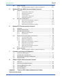
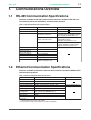
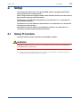


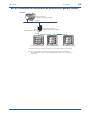
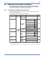

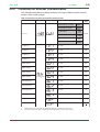

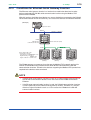


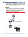
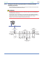


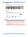
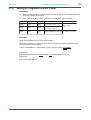
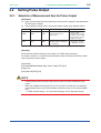


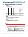

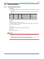
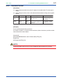
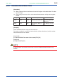


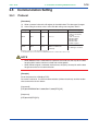
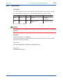
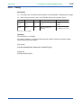

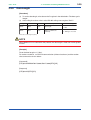


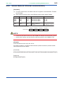
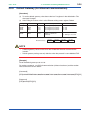

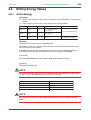
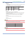
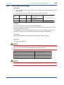


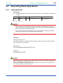

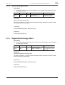
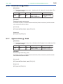

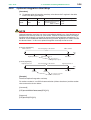
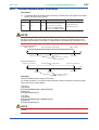
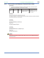

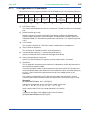
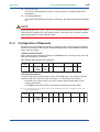

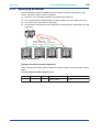
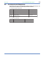
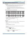
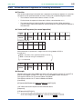

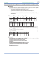


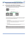
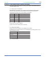


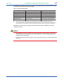


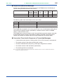


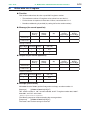
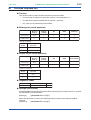


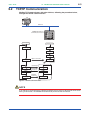
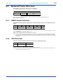


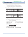
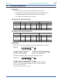


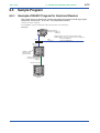
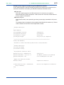
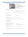
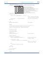


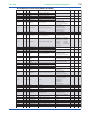


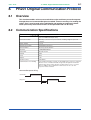


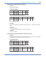
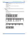
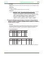


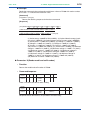


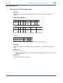
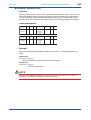
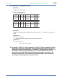


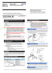
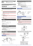


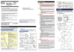
![UPM100, UPM101 小形電力モニタ 通信機能説明書 [6版]](http://vs1.manualzilla.com/store/data/006649598_3-604f1ea4ba68a16d98343de23851f812-150x150.png)