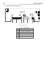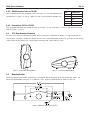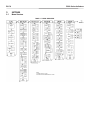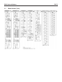
1
5000 Series Indicators Instruction Manual T51P Indicator T51XW Indicator Modification Sheet to this manual p/n 80251400 Section 2.2.1 3.4.1 3.4.4 3.4.5 3.4.9 3.4.10 3.5.2 3.9.1 3.10 5.2 Explanation For connecting bases with a connector to a T51XW (which does not have the external connector), a Load Cell Cable Adapter Kit p/n 80500736 is available as an accessory. This kit connects to the terminal block inside the T51XW and has an external connector on the other end. Reset the Setup menu to the factory defaults (except Range, Capacity and Graduation) Note: Range 2 graduation is retained even under half capacity until the scale returns to zero Note: Units oz, lb:oz and C (custom) will not be valid as Power On units when Range is set to Dual. The next available unit will be displayed instead. When Legal for Trade is on, the following Menu settings are effected: Range, Graduation, Power On unit, Auto-Tare, Retain Zero, Gross Indication, and Print Output settings are locked; Zero Range is locked at 2%; Stable Range is locked at 1d; AZT is set to 0.5d; Capacity is read-only; Continuous Print is disabled; Lock Unit and Lock Mode are turned on; Calibration functions except for Cal Test are hidden; IP and CP RS232 commands are disabled. Beeper volume settings are Off, Low (default), High Stable Range settings are: 0.5d, 1d, 2d, 3d, 5d Note: If LFT is on, the following Print menu settings are not reset: Stable Handshake default setting is “none” Output Format: Field: Length: Weight 9 Space* 1 Unit 5 Space* 1 Stability 1 Space* 1 G/N N Space* 1 Term. Char(s) * *Each field is followed by a single delimiting space (ASCII: 32) Definitions: Weight – up to 9 characters, right justified, “-“ at immediate left of most significant character (if negative). Unit – up to 5 characters Stability – “?” character is printed if not stable. If weight is stable, neither “?” nor following space is printed. G/N – “NET” printed if weight is net weight, “G”, “B”, or nothing (depending on GROSS menu setting – Sec. 3.5.7) printed if weight is a gross weight. *Terminating Character(s) – terminating character(s) printed depending on FEED menu setting (CR,LF / 4xCR,LF / ASCII:12, refer also to Sec. 3.9.5). 6.3 8.2 D51Pxxx scales utilize a load cell cable that is plugged onto the indicator. For EC and OIML type approved applications, the plugged connection must be sealed using the Load Cell Sealing Collar p/n 80500737. Table 8-3: Interface Cable/PC 9-pin, T51P 80500525 Interface Cable/PC 25-pin, T51P 80500524 Interface Cable/Printer SF-42, T51P 80500571 Interface Cable/PC 9-pin, T51XW 80500552 Interface Cable/PC 25-pin, T51XW 80500553 Interface Cable/Printer SF-42, T51XW 80500574 Load Cell Cable Adapter Kit 80500736 Load Cell Cable Sealing Collar 80500737 Note: The next revision of this manual will be updated with these modifications. 5000 Series Indicators EN- TABLE OF CONTENTS 1. 1.1 1.2 1.3 INTRODUCTION...........................................................................................................................................EN-5 Safety Precautions......................................................................................................................................EN-5 1.1.1 Relay Option Safety Precautions.........................................................................................................EN-5 Overview of Parts and Controls . ..................................................................................................................EN-6 Control Functions......................................................................................................................................EN-10 2. 2.1 2.2 2.3 2.4 2.5 INSTALLATION..........................................................................................................................................EN-11 Unpacking...............................................................................................................................................EN-11 External Connections.................................................................................................................................EN-11 2.2.1 Scale Base with Connector to T51P .................................................................................................EN-11 2.2.2 RS232 Interface Cable to T51P........................................................................................................EN-11 2.2.3 AC Power to T51P .........................................................................................................................EN-11 2.2.4 AC Power to T51XW........................................................................................................................EN-11 2.2.5 Battery Power to T51P.....................................................................................................................EN-11 2.2.6 Mounting Bracket............................................................................................................................EN-12 Internal Connections..................................................................................................................................EN-12 2.3.1 Opening the Housing........................................................................................................................EN-12 2.3.2 Scale Base Without Connector to T51P or T51XW .............................................................................EN-12 2.3.3 RS232 Interface Cable to T51XW.......................................................................................................EN-13 2.3.4 Footswitch to T51P or T51XW...........................................................................................................EN-13 T51P Rear Housing Orientation..................................................................................................................EN-13 Mounting Bracket......................................................................................................................................EN-13 3. SETTINGS.................................................................................................................................................EN-14 3.1 Menu Structure.........................................................................................................................................EN-14 3.2 Menu Navigation......................................................................................................................................EN-16 3.3 Calibration Menu......................................................................................................................................EN-16 3.3.1 Zero Calibration.............................................................................................................................EN-17 3.3.2 Span Calibration............................................................................................................................EN-17 3.3.3 Linearity Calibration.......................................................................................................................EN-18 3.3.4 Calibration Test.............................................................................................................................EN-19 3.3.5 Geographical Adjustment Factor......................................................................................................EN-19 3.3.6 End Calibration..............................................................................................................................EN-19 3.4 Setup Menu..............................................................................................................................................EN-21 3.4.1 Reset............................................................................................................................................EN-21 3.4.2 Range..........................................................................................................................................EN-21 3.4.3 Capacity.......................................................................................................................................EN-21 3.4.4 Graduation....................................................................................................................................EN-22 3.4.5 Power On Unit...............................................................................................................................EN-22 3.4.6 Zero Range...................................................................................................................................EN-22 3.4.7 Auto-Tare......................................................................................................................................EN-23 3.4.8 Retain Weight Data........................................................................................................................EN-23 3.4.9 Legal for Trade..............................................................................................................................EN-23 3.4.10Beeper Volume..............................................................................................................................EN-24 EN- 5000 Series Indicators TABLE OF CONTENTS (Cont.) 3.4.11 Beeper Signal................................................................................................................................EN-24 3.4.12Button Beeper................................................................................................................................EN-24 3.4.13 End Setup.....................................................................................................................................EN-24 3.5 Readout Menu..........................................................................................................................................EN-24 3.5.1 Reset............................................................................................................................................EN-25 3.5.2 Stabile Range................................................................................................................................EN-25 3.5.3 Filter.............................................................................................................................................EN-25 3.5.4 Auto-Zero Tracking.........................................................................................................................EN-25 3.5.5 Backlight......................................................................................................................................EN-26 3.5.6 Auto Off Timer...............................................................................................................................EN-26 3.5.7 Gross Indicator...............................................................................................................................EN-26 3.5.8 End Readout..................................................................................................................................EN-26 3.6 Mode Menu..............................................................................................................................................EN-26 3.6.1 Reset............................................................................................................................................EN-27 3.6.2 Weighing Mode.............................................................................................................................EN-27 3.6.3 Parts Counting Mode......................................................................................................................EN-27 3.6.4 Parts Counting Optimize.................................................................................................................EN-27 3.6.5 Percent Weighing Mode..................................................................................................................EN-27 3.6.6 Dynamic Weighing Mode...............................................................................................................EN-27 3.6.7 Check Weighing Mode...................................................................................................................EN-28 3.6.8 End Mode.....................................................................................................................................EN-28 3.7 Unit Menu................................................................................................................................................EN-28 3.7.1 Reset............................................................................................................................................EN-28 3.7.2 Kilogram Unit................................................................................................................................EN-28 3.7.3 Gram Unit.....................................................................................................................................EN-28 3.7.4 Pound Unit....................................................................................................................................EN-29 3.7.5 Ounce Unit....................................................................................................................................EN-29 3.7.6 Pound Ounce Unit..........................................................................................................................EN-29 3.7.7 Tonnes Unit...................................................................................................................................EN-29 3.7.8 Custom Unit..................................................................................................................................EN-29 3.7.9 End Unit.......................................................................................................................................EN-30 3.8 GMP Menu...............................................................................................................................................EN-30 3.8.1 Reset............................................................................................................................................EN-30 3.8.2 Date Type.....................................................................................................................................EN-30 3.8.3 Date Set........................................................................................................................................EN-31 3.8.4 Time Type.....................................................................................................................................EN-31 3.8.5 Time Set.......................................................................................................................................EN-31 3.8.6 User ID.........................................................................................................................................EN-32 3.8.7 Project ID......................................................................................................................................EN-32 3.8.8 Scale ID........................................................................................................................................EN-32 3.8.7 End GMP......................................................................................................................................EN-32 3.9 Print 1, Print 2 Menus...............................................................................................................................EN-33 3.9.1 Reset............................................................................................................................................EN-33 3.9.2 Print Stable data Only.....................................................................................................................EN-33 3.9.3 Auto Print......................................................................................................................................EN-33 3.9.4 Print Content Sub-menu..................................................................................................................EN-34 5000 Series Indicators EN- TABLE OF CONTENTS (Cont.) 3.9.5 Layout Sub-menu..........................................................................................................................EN-36 3.9.6 List Menu Settings..........................................................................................................................EN-36 3.9.7 End Print......................................................................................................................................EN-36 3.10 COM 1, COM 2 Menus..............................................................................................................................EN-36 3.10.1Reset............................................................................................................................................EN-36 3.10.2Baud............................................................................................................................................EN-37 3.10.3Parity...........................................................................................................................................EN-37 3.10.4 Stop Bit.........................................................................................................................................EN-37 3.10.5 Handshake...................................................................................................................................EN-37 3.10.6Address........................................................................................................................................EN-37 3.10.7Alternate Command Sub-menu........................................................................................................EN-38 3.10.8 End COM 1 or End COM 2..............................................................................................................EN-38 3.11 I/O Menu.................................................................................................................................................EN-38 3.11.1Reset............................................................................................................................................EN-38 3.11.2External Input................................................................................................................................EN-39 3.11.3Input Beep....................................................................................................................................EN-39 3.11.4Relay Output.................................................................................................................................EN-39 3.11.5End..............................................................................................................................................EN-40 3.12 Menu Lock Menu ....................................................................................................................................EN-40 3.12.1Reset............................................................................................................................................EN-40 3.12.2Lock Calibration............................................................................................................................EN-40 3.12.3 Lock Setup....................................................................................................................................EN-41 3.12.4Lock Readout................................................................................................................................EN-41 3.12.5Lock Mode....................................................................................................................................EN-41 3.12.6Lock Unit......................................................................................................................................EN-41 3.12.7Lock Print 1..................................................................................................................................EN-41 3.12.8Lock Print 2..................................................................................................................................EN-41 3.12.9Lock Com 1..................................................................................................................................EN-41 3.12.10 Lock Com 2................................................................................................................................EN-41 3.12.11 Lock GMP...................................................................................................................................EN-42 3.12.12 Lock I/O......................................................................................................................................EN-42 3.12.13 End Lock....................................................................................................................................EN-42 3.13 Key Lock Menu........................................................................................................................................EN-42 3.13.1Reset............................................................................................................................................EN-42 3.13.2Lock All Buttons.............................................................................................................................EN-42 3.13.3Lock Off Button..............................................................................................................................EN-42 3.13.4Lock Zero Button............................................................................................................................EN-42 3.13.5Lock Print Button...........................................................................................................................EN-43 3.13.6Lock Unit Button............................................................................................................................EN-43 3.13.7Lock Function Button......................................................................................................................EN-43 3.13.8Lock Mode Button..........................................................................................................................EN-43 3.13.9Lock Tare Button............................................................................................................................EN-43 3.13.10 Lock Menu Button........................................................................................................................EN-43 3.13.11 End Lock....................................................................................................................................EN-43 3.14 Security Switch.................................................................................................................................EN-43 EN- 5000 Series Indicators TABLE OF CONTENTS (Cont.) 4. 4.1 4.2 4.3 4.4 4.5 4.6 4.7 4.8 OPERATION..............................................................................................................................................EN-44 Turning Indicator On/Off.............................................................................................................................EN-44 Zero Operation..........................................................................................................................................EN-44 Manual Tare.............................................................................................................................................EN-44 Pre-Set Tare.............................................................................................................................................EN-44 Auto-Tare.................................................................................................................................................EN-44 Changing Units of Measure........................................................................................................................EN-45 Printing Data............................................................................................................................................EN-45 Application Modes....................................................................................................................................EN-45 4.8.1 Weighing......................................................................................................................................EN-45 4.8.2 Parts Counting..............................................................................................................................EN-45 4.8.3 Percent Weighing..........................................................................................................................EN-46 4.8.4 Check Weighing............................................................................................................................EN-47 4.8.5 Dynamic Weighing........................................................................................................................EN-48 5. 5.1 5.2 5.3 SERIAL COMMUNICATION...........................................................................................................................EN-49 Interface Commands.................................................................................................................................EN-49 Output Format..........................................................................................................................................EN-50 Printouts..................................................................................................................................................EN-50 6. 6.1 6.2 6.3 LEGAL FOR TRADE....................................................................................................................................EN-52 Settings...................................................................................................................................................EN-52 Verification...............................................................................................................................................EN-52 Sealing....................................................................................................................................................EN-52 7. 7.1 7.2 7.3 7.4 MAINTENANCE..........................................................................................................................................EN-53 Model T51P Cleaning................................................................................................................................EN-53 Model T51XW Cleaning.............................................................................................................................EN-53 Troubleshootting.......................................................................................................................................EN-53 Service Information...................................................................................................................................EN-54 8. 8.1 8.2 8.3 8.4 TECHNICAL DATA......................................................................................................................................EN-55 Specifications...........................................................................................................................................EN-55 Accessories and Options............................................................................................................................EN-56 Drawings and Dimensions.........................................................................................................................EN-57 Compliance.............................................................................................................................................EN-58 5000 Series Indicators 1. EN- INTRODUCTION This manual contains installation, operation and maintenance instructions for the T51P and T51XW Indicators. Please read this manual completely before installation and operation. 1.1 Safety Precautions For safe and dependable operation of this equipment, please comply with the following safety precautions: •Verify that the input voltage range printed on the data label matches the local AC power to be used. •Make sure that the power cord does not pose a potential obstacle or tripping hazard. •Use only approved accessories and peripherals. •Operate the equipment only under ambient conditions specified in these instructions. •Disconnect the equipment from the power supply when cleaning. •Do not operate the equipment in hazardous or unstable environments. •Do not immerse the equipment in water or other liquids. •Service should only be performed by authorized personnel. •The T51XW is supplied with a grounded power cable. Use only with a compatible grounded power outlet. 1.1.1 Relay Option Safety Precautions This equipment may have an optional AC or DC Relay Option board installed. This option allows external devices to be controlled by the Indicator. CAUTION: ELECTRICAL SHOCK HAZARD. REMOVE ALL POWER CONNECTIONS TO THE INDICATOR BEFORE SERVICING OR MAKING INTERNAL CONNECTIONS. THE HOUSING SHOULD ONLY BE OPENED BY AUTHORIZED AND QUALIFIED PERSONNEL, SUCH AS AN ELECTRICAL TECHNICIAN. Before making connections to the Relay terminals, remove power from the system. If the system contains an optional rechargeable battery system, be sure that the ON/ZERO Off button is used to fully turn off the system after removing the AC power plug. More detailed installation instructions are included with the Relay Option Kit when purchased. EN- 5000 Series Indicators 1.2 Overview of Parts and Controls 2 3 4 1 5 6 7 8 9 10 11 12 13 14 15 Figure 1-1. T51P Indicator. 16 TABLE 1-1. T51P PARTS. Item Description 1 Data Label 2 Front Housing 3 Control Panel 4 Adjusting Knob (2) 5 Mounting Bracket 6 Security Screw 7 Data Label 8 Rear Housing 9 Battery Cover 10 Screw (4) 11 Power Receptacle 12 Hole plug for option 13 Strain relief for alternate load cell connection 14 Load Cell Connector 15 Hole plug for option 16 RS232 Connector 5000 Series Indicators EN- 1.2 Overview of Parts and Controls (Cont.) 1 2 3 4 5 6 7 8 9 10 11 12 13 Figure 1-2. T51XW Indicator. 14 TABLE 1-2. T51XW PARTS. Item Description 1 Data Label 2 Front Housing 3 Control Panel 4 Adjusting Knob (2) 5 Mounting Bracket 6 Screw (4) 7 Rear housing 8 Data Label 9 Strain relief for option 10 Strain relief for RS232 11 Strain relief for option 12 Strain relief for option 13 Strain relief for Load Cell Cable 14 Power cord EN- 5000 Series Indicators 1.2 Overview of Parts and Controls (Cont.) 1 2 3 4 7 Figure 1-3. Main PC Board. Item TABLE 1-3. MAIN PC BOARD. Description 1 Sense Jumper W1 2 Alternate Load Cell Terminal Block J4 3 Sense Jumper W2 4 Security Switch SW2 5 External input Terminal Block J9 6 RS232 Terminal Block J7 (T51XW only) 7 Load Cell Connector 5 6 5000 Series Indicators EN- 1.2 Overview of Parts and Controls (Cont.) 1 27 26 25 24 23 22 21 20 4 3 2 56 78 9 19 18 17 16 15 14 13 12 11 10 Figure 1-4. Controls and Indicators. TABLE 1-4. CONTROL PANEL. No. Designation No. Designation 1 UNDER LED 15 TARE Menu-Cal button 2 ACCEPT LED 16 Pieces symbol 3 OVER LED 17 FUNCTION Mode button 4 Capacity Label Window 18 PRINT Units button 5 Brackets (not used) 19 ON/ZERO Off button 6 Kilogram, gram symbols 20 7 Scale symbol (not used) Pointer symbols (not used) 8 Range symbol 21 Brutto, Gross symbols 9 Percent symbol 22 10 Pound, Ounce, Pound: ounce symbols Preset Tare, Tare symbols 23 Stable weight Indicator 11 Tonne symbol 24 Negative symbol 12 Battery charge symbol 25 Center of Zero Indicator 13 Custom unit symbol 26 NET symbol 14 Dynamic symbol 27 7-segment Display EN-10 5000 Series Indicators 1.3 Control Functions TABLE 1-5. CONTROL FUNCTIONS. Button Primary Function (Short Press) Secondary Function (Long Press) PRINT ON/ZERO Turns the Indicator Sends the current value on. to the selected COM ports if AUTOPRINT is If Indicator is On, sets set to Off. zero. FUNCTION Initiates an application mode. Off Turns the Indicator off. Mode Allows changing the application mode. Units Changes the weighing Unit. TARE Performs a tare operation. Temporarily displays the active mode’s reference data. Menu-Cal Enter the User menu. Press and hold allows scrolling through modes. Menu Function (Short Press) Yes Accepts the current setting on the display. No Advances to the next menu or menu item. Rejects the current setting on the display and advances to the next available setting. Increments the value. Back Moves Back to previous menu item. Decrements the value. Exit Exits the User menu. Aborts the calibration in progress. 5000 Series Indicators EN-11 2. INSTALLATION 2.1 Unpacking Unpack the following items: •T51P or T51XW Indicator •AC Power Cord (T51P only) •Mounting Bracket •Knobs (2) •Capacity Label Sheet •LFT Sealing kit •Instruction Manual CD •Warranty Card 2.2 External Connections 2.2.1 Scale Base with Connector to T51P Ohaus bases with a connector can be attached to the external load cell connector (Figure 1-1, item 14). Refer to section 2.3.2 for bases without a connector. 2.2.2 RS232 interface Cable to T51P Connect the optional RS232 cable to the RS232 connector (Figure 1-1, item 16). Pin Connection 1 N/C 2 TXD 3 RXD 4 N/C 5 GND 6 N/C 7 CTS 8 RTS 9 N/C 4 5 9 2 3 8 7 1 6 Figure 2-1. RS232 Pins. 2.2.3 AC Power to T51P Connect the AC power cord (supplied) to the power receptacle (Figure 1-1, item 11), then connect the AC plug to an electrical outlet. 2.2.4 AC Power to T51XW Connect the AC plug to a properly grounded electrical outlet. 2.2.5 Battery Power to T51P The indicator can be operated on alkaline batteries (not supplied) when AC power is not available. It will automatically switch to battery operation if there is power failure or the power cord is removed. The indicator can operate for up to 80 hours on battery power. Remove the battery cover (Figure 1-1, item 9) and install 6 C-type (LR14) alkaline batteries in the orientation specified. Re-install the battery cover. During battery operation, the battery charge symbol indicates the battery status. The indicator will automatically turn-off when the batteries are fully discharged. EN-12 5000 Series Indicators 2.2.6 Mounting Bracket Align the wall bracket over the threaded holes in the side of the indicator and install the knobs. Adjust the indicator to the desired angle and tighten the knobs. 2.3 Internal Connections Some connections require the housing to be opened. 2.3.1 Opening the Housing CAUTION: ELECTRICAL SHOCK HAZARD. REMOVE ALL POWER CONNECTIONS TO THE INDICATOR BEFORE SERVICING OR MAKING INTERNAL CONNECTIONS. The housing should only be opened by authorized and qualified personnel, such as an Electrical Technician. T51P Remove the four Phillips head screws from the rear housing. Remove the front housing being careful not to disturb the internal connections. Once all connections are made, reattach the front housing. T51XW Remove the four hex head screws from the rear housing. Open the housing by carefully pulling the front housing forward. Once all connections are made, reattach the front housing. The screws should be tightened fully to maintain a water tight seal. 2.3.2 Scale Base Without Connector to T51P or T51XW Pin Connection Bases without a connector must be attached to the internal load cell connector on the main PC board. Pass the load cell cable through the strain relief (Figure 1-1, item 13 or Figure 1-2, item 13) and attach it to terminal block J4 (Figure 1-3, item 2). Tighten the strain relief to maintain a watertight seal. J4-1 +EXE J4-2 +SEN J4-3 +SIG J4-4 GND J4-5 -SIG J4-6 -SEN J4-7 -EXE Jumper Connections For a 4-wire load cell with no sense wires: Jumpers W1 and W2 must be left in place shorting the two pins. For a 6-wire load cell that includes sense wires, Jumpers W1 and W2 must be removed. For load cells with an extra ground shield wire: Connect the shield to the center position (GND) of J4. Figure 2-2. Jumper Connections. After wiring is completed and jumpers are in place, replace the indicator housing screws. Make sure the liquid-tight connector is properly tightened. 5000 Series Indicators EN-13 2.3.3 RS232 Interface Cable to T51XW Pass the optional RS232 cable through the strain relief (Figure 1-2, item 10) and attach it to terminal block J7 (Figure 1-3, item 6). Tighten the strain relief to maintain a watertight seal. 2.3.4 Footswitch to T51P or T51XW Pin Connection J7-1 RTS J7-2 TXD J7-3 RXD J7-4 CTS J7-5 GND Pass the optional footswitch cable through the strain relief (Figure 1-1, item 15 or Figure 1-2, item 11) and attach it to terminal block J9 (Figure 1-3, item 5). 2.4 T51P Rear Housing Orientation The T51P is delivered in the wall mount orientation with the connections exiting below the display. The rear housing may be reversed so the connections exit above the display when the T51P is placed horizontally on a bench. To reverse the rear housing, remove the four Phillips head screws, carefully rotate the housing 180°, and reinstall the screws. Figure 2-3. Wall Mount Configuration. Figure 2-4. Bench Top Configuration. 2.5 Mounting Bracket Attach the bracket to a wall or table using fasteners (not supplied) that are appropriate for the type of mounting surface. The bracket will accommodate up to 6 mm (1/4”) diameter screws. Locate the mounting holes as shown in Figure 2-4. Figure 2-5 Mounting Bracket Dimensions. EN-14 5000 Series Indicators 3 SETTINGS 3.1 Menu Structure TABLE 3-1. MENU STRUCTURE. 5000 Series Indicators EN-15 3.1 Menu Structure (Cont.) TABLE 3-1. MENU STRUCTURE (Cont.). EN-16 5000 Series Indicators 3.2 Menu Navigation Enter the menu by pressing the Menu-Cal button until MENU is displayed. The first menu is displayed. Press the No or Back button to move to a different menu. Press the Yes button to enter the menu. Once in the menu, press the Yes button to view the menu item setting or press the No or Back button to move to the next menu item. When viewing the setting, press the Yes button to accept the setting, or press the No or Back button to change the setting. Once all settings have been made, press the Exit button to return to the current application mode. For menu items with alphanumeric settings such as Capacity, the current setting is displayed with all digits flashing. Press the No button to begin editing. The first digit is displayed flashing. Press the No button to increment the digit or press the Yes button to accept the digit and move to the next digit. Repeat this process for all digits. Press the Yes button when the last digit has been set. The new setting is displayed with all digits flashing. Press the Yes button to accept the setting or press the No button to resume editing. This method also applies to setting Checkweigh under and over targets. For End menu items, pressing the Yes button advances to the next menu, while pressing the No button returns to the top of the current menu. 3.3 Calibration Menu When CAL is displayed, press the Yes button to accept the Calibration menu selection. Press the No button to advance to the desired calibration menu item. Zero Three calibration processes are available: Zero Calibration, Span Calibration and Span Linearity Calibration. Linearity NOTES: Cal Test 1. Make sure that appropriate calibration masses are available before Geographic beginning calibration. Adjustment 2. Make sure that the scale base is level and stable during the entire End Calibration calibration process. 3. Calibration is unavailable with LFT set to On. 4. Allow the Indicator to warm up for approximately 5 minutes after stabilizing to room temperature. 5. To abort calibration, press the Exit button anytime during the calibration process. 6. When any selection within the GMP menu is enabled, calibration results are automatically printed. Perform Perform Perform Perform Set 00…Set 12…Set 31 Exit CALIBRATE menu 5000 Series Indicators EN-17 3.3.1 Zero Calibration Zero calibration uses one calibration point. The zero calibration point is established with no weight on the scale. Use this calibration method to adjust for a different pre-load without affecting the span or linearity calibration. When ZErO is displayed, press the Yes button to initiate Zero Calibration. The display flashes 0 and the calibration unit. Press the Yes button to establish the zero point. The display shows --C-- while the zero point is established. When zero calibration is completed, the display shows dONE. Then the scale exits to the active weighing mode and displays the actual weight value. 3.3.2 Span Calibration Span Calibration uses two points to adjust the scale. The span calibration point is established with a calibration mass placed on the scale. The zero calibration point is established with no weight on the scale. When SPAN is displayed, press the Yes button to initiate Span Calibration. The display flashes the span calibration point. Place the specified weight on the scale and press the Yes button. To choose a different span point or calibration unit, edit the setting as explained in Section 3.2 Menu Navigation. When the desired setting is displayed, place the specified weight on the scale and press the Yes button. The display shows --C-- while the span point is established. The display flashes 0. With no weight on the scale, press the Yes button to establish the zero point. The display shows --C-- while the zero point is established. When span calibration is completed, the display shows dONE. Then the scale exits to the active weighing mode and displays the actual weight value. EN-18 5000 Series Indicators 3.3.3 Linearity Calibration Linearity calibration uses 3 calibration points. The full calibration point is established with a weight on the scale. The mid calibration point is established with a weight equal to half of the full calibration weight on the scale. The zero calibration point is established with no weight on the scale. The mid calibration points cannot be altered by the user during the calibration procedure. When LINEAr is displayed, press the Yes button to initiate Linearity Calibration. The display flashes the full calibration point and calibration unit. Place the specified weight on the scale and press the Yes button. To choose a different full point or calibration unit (kg or lb), edit the setting as explained in Section 3.2 Menu Navigation. When the desired setting is displayed, place the specified weight on the scale and press the Yes button. The display shows --C-- while the full point is established. The display flashes the mid calibration point. Place the specified weight on the scale and press the Yes button. The display shows --C-- while the mid point is established. The display flashes 0. With no weight on the scale, press the Yes button to establish the zero point. The display shows --C-- while the zero point is established. When linearity calibration is completed, the display shows dONE. Then the scale exits to the active weighing mode and displays the actual weight value. 5000 Series Indicators EN-19 3.3.4 Calibration Test Calibration test is used to compare a known calibration weight against the stored span calibration data. NOTE: Calibration Test is always available (even when LFT is set to ON). When tESt is displayed, press the Yes button to initiate Calibration Test. The display flashes 0. With no weight on the scale, press the Yes button to record the current zero point. The display shows --t-- while the zero point is recorded. The display flashes the span calibration weight using the value from the last calibration. The example shows test weight of 30 kg. Place the specified test weight on the scale and press the Yes button. The display shows --t-- while the data is processed. The display flashes the actual difference between the calibration data and the test weight. The example shows a 0.010 kg difference. The result of the Calibration Test is printed. After 5 seconds, Calibration Test ends, the scale returns to the active weighing mode and displays the current weight. 3.3.5 Geographical Adjustment Factor Refer to table 3-3 and set the GEO factor that corresponds to your location. 00 to 31 • • • 3.3.6 End Calibration Advance to the next menu. EN-20 5000 Series Indicators TABLE 3-2. GEOGRAPHICAL ADJUSTMENT VALUES latitude Geographical away from the equator, (North or South) in and minutes. degrees 0°00’ - 5°46’ 5°46’ - 9°52’ 9°52’ - 12°44’ 12°44’ - 15°06’ 15°06’ - 17°10’ 17°10’ - 19°02’ 19°02’ - 20°45’ 20°45’ - 22°22’ 22°22’ - 23°54’ 23°54’ - 25°21’ 25°21’ - 26°45’ 26°45’ - 28°06’ 28°06’ - 29°25’ 29°25’ - 30°41’ 30°41’ - 31°56’ 31°56’ - 33°09’ 33°09’ - 34°21’ 34°21’ - 35°31’ 35°31’ - 36°41’ 36°41’ - 37°50’ 37°50’ - 38°58’ 38°58’ - 40°05’ 40°05’ - 41°12’ 41°12’ - 42°19’ 42°19’ - 43°26’ 43°26’ - 44°32’ 44°32’ - 45°38’ 45°38’ - 46°45’ 46°45’ - 47°51’ 47°51’ - 48°58’ 48°58’ - 50°06’ 50°06’ - 51°13’ 51°13’ - 52°22’ 52°22’ - 53°31’ 53°31’ - 54°41’ 54°41’ - 55°52’ 55°52’ - 57°04’ 57°04’ - 58°17’ 58°17’ - 59°32’ 59°32’ - 60°49’ 60°49’ - 62°09’ 62°90’ - 63°30’ 63°30’ - 64°55’ 64°55’ - 66°24’ 66°24’ - 67°57’ 67°57’ - 69°35’ 69°35’ - 71°21’ 71°21’ - 73°16’ 73°16’ - 75°24’ 75°24’ - 77°52’ 77°52’ - 80°56’ 80°56’ - 85°45’ 85°45’ - 90°00’ Elevation above sea level in meters 0 325 650 975 325 650 975 1300 Elevation above sea level in feet 0 1060 2130 3200 1060 2130 3200 4260 5 4 4 3 5 5 4 4 6 5 5 4 6 6 5 5 7 6 6 5 7 7 6 6 8 7 7 6 8 8 7 7 9 8 8 7 9 9 8 8 10 9 9 8 10 10 9 9 11 10 10 9 11 11 10 10 12 11 11 10 12 12 11 11 13 12 12 11 13 13 12 12 14 13 13 12 14 14 13 13 15 14 14 13 15 15 14 14 16 15 15 14 16 16 15 15 17 16 16 15 17 17 16 16 18 17 17 16 18 18 17 17 19 18 18 17 19 19 18 18 20 19 19 18 20 20 19 19 21 20 20 19 21 21 20 20 22 21 21 20 22 22 21 21 23 22 22 21 23 23 22 22 24 23 23 22 24 24 23 23 25 24 24 23 25 25 24 24 26 25 25 24 26 26 25 25 27 26 26 25 27 27 26 26 28 27 27 26 28 28 27 27 29 28 28 27 29 29 28 28 30 29 29 28 30 30 29 29 31 30 30 29 1300 1625 1950 2275 2600 2925 3250 1625 1950 2275 2600 2925 3250 3575 4260 5330 3 3 4 4 5 5 6 6 7 7 8 8 9 9 10 10 11 11 12 12 13 13 14 14 15 15 16 16 17 17 18 18 19 19 20 20 21 21 22 22 23 23 24 24 25 25 26 26 27 27 28 28 29 5330 6400 2 3 3 4 4 5 5 6 6 7 7 8 8 9 9 10 10 11 11 12 12 13 13 14 14 15 15 16 16 17 17 18 18 19 19 20 20 21 21 22 22 23 23 24 24 25 25 26 26 27 27 28 28 6400 7460 8530 9600 10660 7460 8530 9600 10660 11730 2 1 1 0 0 2 2 1 1 0 3 2 2 1 1 3 3 2 2 1 4 3 3 2 2 4 4 3 3 2 5 4 4 3 3 5 5 4 4 3 6 5 5 4 4 6 6 5 5 4 7 6 6 5 5 7 7 6 6 5 8 7 7 6 6 8 8 7 7 6 9 8 8 7 7 9 9 8 8 7 10 9 9 8 8 10 10 9 9 8 11 10 10 9 9 11 11 10 10 9 12 11 11 10 10 12 12 11 11 10 13 12 12 11 11 13 13 12 12 11 14 13 13 12 12 14 14 13 13 12 15 14 14 13 13 15 15 14 14 13 16 15 15 14 14 16 16 15 15 14 17 16 16 15 15 17 17 16 16 15 18 17 17 16 16 18 18 17 17 16 19 18 18 17 17 19 19 18 18 17 20 19 19 18 18 20 20 19 19 18 21 20 20 19 19 21 21 20 20 19 22 21 21 20 20 22 22 21 21 20 23 22 22 21 21 23 23 22 22 21 24 23 23 22 22 24 24 23 23 22 25 24 24 23 23 25 25 24 24 23 26 25 25 24 24 26 26 25 25 24 27 26 26 25 25 27 27 26 26 25 28 27 27 26 26 5000 Series Indicators EN-21 3.4 Setup Menu When the Indicator is used for the first time, enter this menu to set the Range, Capacity and Graduation. Reset Range Full Scale Capacity Graduation Power On unit Zero Range Auto-Tare Retain Weight Data Legal for Trade Beeper Volume Beeper Signal Button Beep End Setup No, Yes Single, Dual 1…999950 0.00001…1000 Auto, kg, g, lb, oz, lb:oz 2%, 100% Off, On, Accept Off, On Off, On Off, Lo, Hi Off, Accept, Under, Over, Under-Over Off, On Exit SETUP menu 3.4.1 Reset Reset the Setup menu to the factory defaults. No = not reset. Yes = reset. NOTE: If the Legal for Trade menu item is set to ON, the Range, Capacity, Graduation, Zero Range, Auto Tare, Retain Weight Data and Legal For Trade settings are not reset. 3.4.2 Range Set the number of weighing ranges. SINGLE = one weighing range from zero to Capacity. DUAL = two weighing ranges, Range 1 is from zero to half Capacity and Range 2 is from half Capacity to Capacity. 3.4.3 Capacity Set the scale capacity as explained in Section 3.2 Menu Navigation. NOTE: If dUAL was selected in the rANGE menu item, the Capacity setting defines the Range 2 capacity. The Range 1 capacity is automatically defined as half of the Capacity setting. For example, if Capacity is set to 15, the Range 1 capacity becomes 7.5. After the capacity is set, select the Primary Unit. kg = the primary unit is kilograms lb. = the primary unit is pounds EN-22 5000 Series Indicators 3.4.4 Graduation Set the scale readability. 0.00001, 0.00002, 0.00005, 0.0001, 0.0002, 0.0005, 0.001, 0.002, 0.005, 0.01, 0.02, 0.05, 0.1, 0.2, 0.5, 1, 2, 5, 10, 20, 50, 100, 200, 500, 1000. NOTE: Graduation settings are limited to values from Capacity divided by 1000 to Capacity divided by 30000. Therefore, not all settings are available for each capacity. NOTE: If dUAL was selected in the rANGE menu item, the Graduation setting defines the Range 1 graduation. The Range 2 graduation is automatically defined as one step greater than the Graduation setting. For example, if Graduation is set to 0.001, the Range 2 graduation becomes 0.002. 3.4.5 Power On Unit Set the unit of measures displayed at startup Auto = last unit in use when turned off PWr.UN kg = kilograms PWr.UN g = grams PWr.UN lb = pounds PWr.UN oz = ounces PWr.UN lb:oz= pound ounces PWr.UN t = tonnes PWr.UN C = custom unit 3.4.6 Zero Range Set the percentage of scale capacity that may be zeroed. 2% = zero up to 2 percent of capacity 100% = zero up to full capacity • • • 5000 Series Indicators 3.4.7 Auto-Tare Set the Automatic Tare functionality. OFF = Automatic Tare is disabled. ON = the first stable gross weight will be tared. ACCEPt = when the application mode is CHECK, stable gross weight that is within the Checkweigh accept limits will be tared. When Accept is selected, set the current delay time is displayed. Settings: OFF = automatic tare takes affect immediately 0.5, 2 or 5 = automatic tare takes affect after the selected delay period (in seconds). 3.4.8 Retain Weight Data Set the Retain Weight Data functionality. OFF = Disabled. ON = When power is turned on, the displayed weight is based on the last stored zero (Zero button or “Z” command). 3.4.9 Legal for Trade Set the legal for trade status. OFF = standard operation ON = operation complies with weights and measures regulations EN-23 EN-24 5000 Series Indicators 3.4.10 Beeper Volume Set the beeper volume. Low = soft. Medium = medium. High = loud. 3.4.11Beeper Signal Set how the beeper responds in the Checkweigh mode. Off = the beeper is disabled. Accept = the beeper will sound when the weight is within the Accept range. Under = the beeper will sound when the weight is below the Under setting. Over = the beeper will sound when the weight is above the Over setting. Under- Over = the beeper will sound when the weight is below the Under setting or above the Over setting. 3.4.12Button Beeper Set how the beeper sounds when a button is pressed. OFF = no sound ON = sound 3.4.13End Setup Advance to the next menu. 3.5 Readout Menu Enter this menu to customize display functionality. Reset: No, Yes Stable Range 0.5d, 1d, 2d, 5d Filter Level Lo, Med, Hi Auto Zero Tracking Backlight Auto Shut Off Gross Indicator End Readout Off, 0.5d, 1d, 3d Off, On, Auto (->Set 1, Set 2, Set 5) Off, Set 1, Set 2, Set 5 Off, Gross, Brutto Exit READOUT menu 5000 Series Indicators 3.5.1 Reset Set the Readout menu to factory default settings. No = not reset Yes = reset If the Legal for Trade menu item is set to ON, the Stable Range, Averaging Level, Auto Zero Tracking, Auto Off and Gross settings are not reset. 3.5.2 Stable Range Set the amount the reading can vary before the stability symbol turns off. 0.5d = 0.5 scale division 1d = 1 scale division 2d = 2 scale divisions 5d = 5 scale divisions NOTE: When LFT is set to ON, the setting is forced to 1 d. The setting is locked when the hardware lock switch is set to the ON position. 3.5.3 Filter Set the amount of signal filtering. LO = less stability, faster stabilization time (<1 sec.) MEd = normal stability, stabilization time (<2 sec.) HI = greater stability, slower stabilization time (<3 sec.) 3.5.4 Auto-Zero Tracking Set the automatic zero tracking functionality. OFF = disabled. 0.5 d = the display will maintain zero until a drift of 0.5 divisions per second has been exceeded. 1 d = the display will maintain zero until a drift of 1 division per second has been exceeded. 3 d = the display will maintain zero until a drift of 3 divisions per second has been exceeded. NOTE: When the LFT menu item is set to ON, the selections are limited to 0.5d and 3d. The setting is locked when the hardware lock switch is set to the ON position. EN-25 EN-26 5000 Series Indicators 3.5.5 Backlight Set the display backlight functionality. OFF = always off. ON = always on. AUtO = turns on when a button is pressed or the displayed weight changes. When Auto is selected, set Backlight shut off time. Settings: SEt 1 = backlight turns off after 1 minute of no activity. SEt 2 = backlight turns off after 2 minute of no activity. SEt 5 = backlight turns off after 5 minute of no activity. 3.5.6 Auto Off Timer Set the automatic shut off functionality. OFF = disabled SEt 1 = powers off after 1 minute of no activity. SEt 2 = powers off after 2 minutes of no activity. SEt 5 = powers off after 5 minutes of no activity. 3.5.7 Gross Indicator Set the type of gross indicator. OFF = disabled G GrOSS = the G icon is lit when gross weights are displayed. B brutto = the B icon is lit when gross weights are displayed. 3.5.8 End Readout Advance to the next menu. 3.6 Mode Menu Enter this menu to activate the desired application modes. Reset: No, Yes Weigh: Count: Percent: Dynamic: Checkweigh: End Mode Off, On Off, On (-> Piece weight optimization (-> On, Off)) Off, On Off, Manual (-> Set 0 … Set 60), Semi-automatic (-> Set 0 … Set 60), Automatic (-> Set 0 … Set 60) Off, On Exit MODE menu 5000 Series Indicators 3.6.1 Reset Set the Mode menu to the factory defaults. No = not reset. Yes = reset. NOTE: If the Legal for trade menu item is set ON, the settings are not reset. 3.6.2 Weighing Mode Set the status. OFF = Disabled ON = Enabled 3.6.3 Parts Counting Mode Set the status. OFF = Disabled ON = Enabled 3.6.4 Parts Counting Optimize Set the status. OFF = Disabled ON = Enabled 3.6.5 Percent Weighing Mode Set the status. OFF = Disabled ON = Enabled 3.6.6 Dynamic Weighing Mode Set the status. OFF = Disabled MAN = averaging and resetting are initiated manually by pressing the FUNCTION button. SEMI = averaging is automatically initiated when the display is stable; resetting is initiated by pressing the FUNCTION button. AUtO = averaging is automatically initiated when the display is stable; resetting is automatically initiated when the weight on the display is < 5 divisions. If MAN, SEMI or AUtO is selected, the current level setting is displayed. Set the averaging time. SEt 0 = the first stable weight will be held on the display until it is reset (display hold). SEt 1 = the weight readings will be averaged for 1 second. The average will be held on the display until it is reset. SEt 60 = the weight readings will be averaged for 60 seconds. The average will be held on the display until it is reset. EN-27 EN-28 5000 Series Indicators 3.6.7 Check Weighing Mode Set the status. OFF = Disabled ON = Enabled 3.6.8 End Mode Advance to the next menu. 3.7 Unit Menu Enter this menu to activate the desired units. Default settings are bold. Note: Due to national laws, the indicator may not include some of the units of measure listed. 3.7.1 Reset Set the Unit menu to the factory defaults. Settings: NO = not reset. YES =reset If the Legal for Trade menu item is set ON, the settings are not reset. 3.7.2 Kilogram Unit Set the status. OFF = Disabled ON = Enabled 3.7.3 Gram Unit Set the status. OFF = Disabled ON = Enabled Reset: Kilograms: Pounds: Grams: Ounces: Pounds:Ounces Tonnes: Custom: End Unit No, Yes Off, On Off, On Off, On Off, On Off, On Off, On Off, On (-> Factor, Exponent, LSD) Exit UNIT menu 5000 Series Indicators EN-29 3.7.4 Pound Unit Set the status. OFF = Disabled ON = Enabled 3.7.5 Ounce Unit Set the status. OFF = Disabled ON = Enabled NOTE: Ounce Unit is not available when Range is set to Dual. 3.7.6 Pound Ounce Unit Set the status. OFF = Disabled ON = Enabled NOTE: Pound Ounce Unit is not available when Range is set to Dual. 3.7.7 Tonnes Unit Set the status. OFF = Disabled ON = Enabled 3.7.8 Custom Unit Use Custom Unit to define an alternate unit of measure, where Custom unit = Factor x Exponent x grams. For example: 1 troy ounce = 373.2417216 grams, so Factor = 3.73242, Exponent = 2. Set the status. OFF = Disabled ON = Enabled NOTE: Custom Unit is not available when Range is set to Dual. Factor Set the conversion factor. 0.00001 to 9.99999 Refer to Section 3.2 Menu Navigation to enter settings. Exponent Set the factor multiplier. 0 = Factor x 1 1 = Factor x 10 2 = Factor x 100 3 = Factor x 1000 -2 = Factor ÷ 100 -1 = Factor ÷ 10 • • • EN-30 5000 Series Indicators Least Significant Digit Set the custom unit readability. 0.00001, 0.00002, 0.00005, 0.0001, 0.0002, 0.0005, 0.001, 0.002, 0.005, 0.01, 0.02, 0.05, 0.1, 0.2, 0.5, 1, 2, 5, 10, 20, 50, 100, 200, 500, 1000 NOTE: LSD settings are limited to values that result in a displayed resolution of 1000 to 30000 divisions. • • • 3.7.9 End Unit Advance to the next menu. 3.8 GMP Menu Enter this menu to set the data for Good Manufacturing Practice. Reset No, Yes Date Time User ID Project ID Scale ID End GMP 3.8.1 Reset Set the GMP menu to factory defaults. NO =not reset. YES = reset. 3.8.2 Date Type Set the date format. MDY = Month.Day.Year DMY = Day.Month.Year YMD = Year.Month.Day Type (->MDY, DMY, YMD) Set 00.00.00 … 99.99.99 Type (-> 24 hr, 12 hr) Set HH:MM or HH:MM A/P 000000 … 999999 000000 … 999999 000000 … 999999 Exit GMP menu 5000 Series Indicators EN-31 3.8.3 Date Set Set the date. 00 to 99 = year position 01 to 12 =month position 01 to 31 = day position Refer to Section 3.2 Menu Navigation to enter settings. 3.8.4 Time Type Set the time format. 24 hr = 24 hour format. 12 hr = 12 hour format. 3.8.5 Time Set Set the time. 24 hour format 00 to 24 =hour position 00 to 59 = minute position (current time blinking) (Set hours 00 to 23) (Set minutes 00 to 59) 12 hour format 12 hr = 12 AM to 12 PM hour position = 00 to 59 minute position Refer to Section 3.2 Menu Navigation to enter settings. (current time blinking) (Set hours 01 to 12 A or P) (Set minutes 00 to 59) EN-32 3.8.6 User ID Set the user identification. 000000 to 999999 Refer to Section 3.2 Menu Navigation to enter settings. 3.8.7 Project ID Set the Project identification. 000000 to 999999 Refer to Section 3.2 Menu Navigation to enter settings. 3.8.8 Scale ID Set the Scale identification. 000000 to 999999 Refer to Section 3.2 Menu Navigation to enter settings. 3.8.9 End GMP Advance to the next menu. 5000 Series Indicators 5000 Series Indicators EN-33 3.9 Print 1 and Print 2 Menus The table shows the items in the Print menu. Default settings are bold. Enter this menu to define printing parameters. NOTE: The Print 2 menu is only displayed if a second interface (RS232 or RS422/RS485) is installed. 3.9.1 RESET Set the Print menu to factory defaults. NO = not reset. YES = reset. NOTE: If the Legal for Trade menu item is set to ON, the following settings are not reset: Stable, Auto Print Reset Stable Only Auto Print Print Content Layout feed) List End Print1 (End Print2) No, Yes Off, On Off, On Stable (-> Load, Load and Zero), Interval (-> 0…3600), Continuous, On Accept Result (-> Off, On, Numeric only), Gross (-> Off, On), Net (-> Off, On), Tare (-> Off, On), Header ( ->Off, On), User ID (-> Off, On), Project ID (-> Off, On), Scale ID (-> Off, On), Difference (-> Off, On), Date and Time (-> Off, On), Information (-> Off, On), Application Mode ( Off, On), Name (-> Off, On), Format (-> Multiple, Single), Feed (-> Line feed, 4 Line feed, Form No, Yes Exit PRINT1 menu Exit PRINT2 menu 3.9.2 Print Stable Data Only Set the print critera. OFF = values are printed immediately. ON = values are only printed when the stability criteria are met. 3.9.3 Auto Print Set the automatic printing functionality. OFF = disabled. ON.StAb = printing occurs each time the stability criteria are met. INtEr = printing occurs at the defined interval. CONt = printing occurs continuosly. ACCEPt = printing occurs each time the display is within the Checkweigh accept range and stability criteria are met. EN-34 When INtEr is selected, set the Print Interval. 1 to 3600 (seconds) 3.9.4 Print Content Sub-menu This sub-menu is used to define the content of the printed data. Result Set the status. OFF = Disabled ON = the displayed reading is printed. NUM = only the numeric portion of the displayed reading is printed. Gross Set the status. OFF = Disabled. ON = the Gross weight is printed. Net Set the status. OFF = Disabled. ON = the Net weight is printed. Tare Set the status. OFF = Disabled. ON = the Tare weight is printed. Header Set the status. OFF = Disabled. ON = the Header is printed. User ID Set the status. OFF = Disabled. ON = the User ID is printed. 5000 Series Indicators 5000 Series Indicators Project ID Set the status. OFF = Disabled. ON = the Project ID is printed. Scale ID Set the status. OFF = Disabled. ON = the Scale ID is printed. Time Set the status. OFF = Disabled. ON = the Date and Time is printed. Difference Set the status. OFF = Disabled. ON = the Calibration Test difference is printed. Reference Information Set the status. OFF = Disabled. ON = the Reference Information is printed. NOTE: Mode Set the status. OFF = Disabled. ON = the Mode is printed. Name Set the status. OFF = Disabled. ON = the Name line is printed. EN-35 EN-36 5000 Series Indicators 3.9.5 Layout Sub-menu This sub-menu is used to define format of data output to a printer or computer. Format Set the printing format. MULtI = a multi-line (single column style) printout is generated. A CRLF is added after each item. SINGLE = a single line printout is generated. (A TAB space is added between each item and a CLRF is used only after the very last item.) Line Feed Set the paper feed. Settings: LINE = move paper up one line after printing 4.LINE = move paper up four lines after printing FOrM = a form feed is appended to the printout 3.9.6 List Menu Settings Print the menu settings. NO = do not print. YES = print. 3.9.7 End Print Advance to the next menu. 3.10 COM 1 and COM 2 Menus The table shows the items in the communication menus. Default settings are bold. Enter the menu to define communication parameters. NOTE: The COM2 menu is only displayed if a second interface (RS232 or RS422/RS485) is installed. 3.10.1Reset Set the COM1 and COM2 menu to factory defaults. NO = not reset. YES = reset. Reset: Baud Rate: Parity: Handshake: Address: Alt Command: Zero End Com1 (End Com2) No, Yes 300, 600, 1200, 2400, 4800, 9600, 19200 7 Even, 7 Odd, 7 None, 8 None Off, XON/XOFF, Hardware Off, 01,…, 99 Print (-> Off, A … P … Z), Tare (-> Off, A … T … Z), (-> Off, A … Z) Exit COM1 menu Exit COM2 menu 5000 Series Indicators EN-37 3.10.2Baud Set the Baud rate. 300 600 1200 2400 4800 9600 19200 = 300 bps = 600 bps =1200 bps = 2400 bps = 4800 bps = 9600 bps = 19200 bps 3.10.3Parity Set the data bits and parity. 7 EVEN = 7 data bits, even parity. 7 Odd = 7 data bits, odd parity. 7 NONE = 7 data bits, no parity. 8 NONE = 8 data bits, no parity. 3.10.4 Stop Bit Set the number of stop bits. 1 = 1 stop bit. 2 = 2 stop bits. 3.10.5Handshake Set the flow control method. NONE = no handshaking. ON-OFF = XON/XOFF software handshaking. HArd = hardware handshaking. 3.10.6Address Set the communication address. NOTE: Address is only displayed in the COM2 menu if the RS422/RS485 option is installed. OFF = no address. 01 to 99 = address 01 to 99 • • • EN-38 5000 Series Indicators 3.10.7Alternate Command Sub-menu Enter this sub-menu to set a different command character for the P (Print), T (Tare) and Z (Zero) commands. Alternate Print Command set the alternate command character for Print. A to Z. Alternate Tare Set the alternate command character for Tare. A to Z. Alternate Zero Set the alternate command character for Zero. A to Z. 3.10.8 End COM1 or End COM2 Advance to the next menu. 3.11 I/O Menu Enter this menu to set the optional input and output device parameters. Default settings are bold. Reset No, Yes External Input Input Beep Relay Output End.I-O 3.11.1 Reset Set the I/O menu to factory defaults NO = not reset. YES = reset. Off, Tare, Zero, Print, Function, Start-Stop, Tare-Start-Stop Off, On Type (-> Open, Closed), Sequence (-> Normal, Hold), Contact (-> Simultaneous, Break- Before-Make, Make-Before-Break) When Stable (-> Off, On) Exit I-O menu 5000 Series Indicators 3.11.2 External Input set the function to be controlled by an optional external input device such as a foot switch. OFF = disabled. tAre = Tare function. ZErO = Zero function. PrINt = Print function. FUNCt = action specific to the current application mode. Start-Stop = the first external input changes the state of the relay. The second external input (S-S) returns the relay to the original state. Tare-Start-Stop = the first external input initiates a Tare function, the second external input (t-S-S) changes the state of the relay. The third external input returns the relay to its original state. 3.11.4 Input Beep Set the beeper response to an external input. OFF = Disabled. ON = Enabled. 3.11.4 Relay Output Set the relay output parameters. NOTE: If the Relay option is not installed the OUTPUT menu and associated menu items are not available. Type Set the initial state of the relay. OPEN = the relay output is normally open. CLOSEd = the relay output is normally closed. CAUTION: The normally closed relay condition is only active while the Indicator is powered on. When powered off or when power is removed, the relay condition returns to a normally open condition. Restoring power to the Indicator will restore the closed condition of the relays. Output Sequence Set how the relay outputs react as the weight reading changes from under / accept / over. NOrM = the previously enabled relay will be disabled as the next relay is enabled. HOLd = the previously enabled relay will hold the same state as the next relay is enabled. EN-39 EN-40 5000 Series Indicators Contact Set the timing of the relay contacts. NOTE: A 100 ms delay or over-lap is used for the bbM and Mbb timing. SIM = relays open or close at the same time. b-b-M = relay opens before the next relay closes. M-b-b = relay closes before the next relay opens. Stable Set how the relay outputs react during instability. OFF = relay changes are immediate. ON = delays relay changes until weight reading is stable. 3.11.5 End Advance to the next menu. 3.12 Menu Lock Menu Enter this menu. Default settings are bold. 3.12.1Reset Set the menu Lock menu to factory defaults. NO = not reset. YES = reset. NOTE: Settings for LFT controlled menu items are not reset. 3.12.2Lock Calibration Set the status. OFF = Calibration menu is not locked. ON = Calibration menu settings is locked. Reset: Lock Calibration Menu Lock Setup Menu Lock Readout Menu Lock Mode Menu Lock Unit Menu Lock Print-1 Menu Lock Print-2 Menu Lock Com-1 Menu Lock Com-2 Menu Lock GMP Menu Lock I/O Menu End Lock Menu No, Yes Off, On Off, On Off, On Off, On Off, On Off, On Off, On Off, On Off, On Off, On Off, On 5000 Series Indicators 3.12.3Lock Setup Set the status. OFF = Setup menu is not locked. ON = Setup menu is locked. 3.12.4Lock Readout Set the status. OFF = Readout menu is not locked. ON = Readout menu is locked. 3.12.5 Lock Mode Set the status. OFF = Mode menu is not locked. ON = Mode menu is locked.. 3.12.6Lock Unit Set the status. OFF = Unit menu is not locked. ON = Unit menu is locked. 3.12.7Lock Print 1 Set the status. OFF = Print 1 menu is not locked. ON = Print 1 menu is locked. 3.12.8Lock Print 2 Set the status. OFF = Print 2 menu is not locked. ON = Print 2 menu is locked. 3.12.9Lock Com 1 Set the status. OFF = COM1 menu is not locked. ON = COM1 menu is locked. 3.12.10 Lock Com 2 Set the status. OFF = COM2 menu is not locked. ON = COM2 menu is locked. EN-41 EN-42 5000 Series Indicators 3.12.11 Lock GMP Set the status. OFF = GMP menu is not locked. ON = GMP menu is locked. 3.12.12Lock I-O Set the status. OFF = I-O menu is not locked. ON = I-O menu is locked. 3.12.13End Lock Advance to the next menu. 3.13 Key Lock Menu Enter this menu to lock buttons. Default settings are bold. 3.13.1Reset Set the Key lock menu to factory defaults. NO = not reset. YES = reset. 3.13.2Lock all Buttons Set the status. OFF = all buttons unlocked. ON = all buttons are locked. 3.13.3 Lock Off Button Set the status. OFF = Off button is unlocked. ON = Off button is locked. 3.13.4Lock Zero Button Set the status. OFF = Zero button is unlocked. ON = Zero button is locked. Reset Lock All Buttons Lock Off Button Lock Zero Button Lock Print Button Lock Unit Button Lock Function Button Lock Mode Button Lock Tare Button Lock Menu Button End Lock Button No, Yes Off, On Off, On Off, On Off, On Off, On Off, On Off, On Off, On Off, On 5000 Series Indicators EN-43 3.13.5Lock Print Button Set the status. OFF = Print button is unlocked. ON = Print button is locked. 3.13.6 Lock Unit Button Set the status. OFF = Unit button is unlocked. ON = Unit button is locked. 3.13.7Lock Function Button Set the status. OFF = Function button is unlocked. ON = Function button is locked. 3.13.8Lock Mode Button Set the status. OFF = Mode button is unlocked. ON = Mode button is locked. 3.13.9Lock Tare Button Set the status. OFF = Tare button is unlocked. ON = Tare button is locked. 3.13.10 Lock Menu Button Set the status. OFF = Menu button is unlocked. ON = Menu button is locked. NOTE: When the Menu button is locked, the user may unlock this button by holding the Menu button for 10 seconds until UNLOCK is displayed. The hardware Lock Switch must be in the unlocked position. 3.13.11 End Lock Advance to the next menu. 3.14 Security Switch A slide switch is located on the Main PCB board. When the switch is set to the on position, user menu settings that were locked in the Menu Lock and Key Lock menus can be viewed but not changed. Open the housing as explained in Section 2.3.1. Set the position of security switch SW2 to ON as shown in Figure 1-3. EN-44 5000 Series Indicators 4 OPERATION 4.1 Turning Indicator On/Off To turn the Indicator on, press the ON/ZERO Off button. The Indicator performs a display test followed by a series of informational displays, and then enters the active weighing mode. To turn the Indicator off, press and hold the ON/ZERO Off button until OFF is displayed. 4.2 Zero Operation Zero can be set under the following conditions: •Automatically at Power On (initial zero). •Semi-automatically (manually) by pressing the ON/ZERO Off button. •Semi-automatically by sending the Zero command (Z or alternate zero command). Press the ON/ZERO Off button to zero the weight display. The scale must be stable to accept zero operation. 4.3 Manual Tare When weighing an item that must be held in a container, taring stores the container weight in memory. Place the empty container on the scale (example 0.5 kg) and press the TARE button. The display will show the net weight. To clear the Tare value, empty the scale and press the TARE button. The display will show the gross weight. 4.4 Pre-Set Tare A Pre-set Tare (PT) is a known tare value entered using the xT command (example 1.234 kg). The display will show the Pre-set Tare as a negative value, with the PT Indicator on. NOTES: 1.The PT value will supersede any other Tare or PT value in memory. 2.When using Pre-Set Tare, make sure that Auto-Tare function is set off in the Setup menu. 3.If the Tare entry includes digits beyond the readability of the Indicator, the tare value is rounded off to the readability of the Indicator. To clear a Pre-set Tare value, empty the scale then press the TARE button. The display will show the Gross weight. 4.5 Auto-Tare Auto-Tare automatically tares the initial weight (such as a container) placed on the empty scale, without having to press the TARE button. The tare value is cleared automatically when the weight on the scale is fully removed. During Checkweighing operation, if the On Accept setting is selected in the Setup menu, weight values that are within the accept range will be tared automatically. NOTE: Auto-Tare supersedes any pre-set (PT) value in memory. 5000 Series Indicators EN-45 4.6 Changing Units of Measure Press and hold the PRINT Units button until the desired measuring unit appears. Only measuring units enabled in the Unit Menu will be displayed (refer to Section 3.7). 4.7 Printing Data Printing the displayed data to a printer or sending the data to a computer requires that the communication parameters in the Print and Communication Menu are set (refer to Sections 3.9 and 3.10). Press the PRINT Units button to send the displayed data to the communication port (the Auto-Print Mode in Section 3.9 function must be Off). 4.8 Application Modes Press and hold the FUNCTION button until the desired application mode appears. Only modes enabled in the mode menu will be displayed (refer to Section 3-8). 4.8.1Weighing Place the item to be weighed on the scale. The illustration indicates a sample of 1.5 kg, Gross weight. NOTE: Press the FUNCTION button to temporarily display the weight in 10x expanded resolution. 4.8.2 Parts Counting Use this mode to count parts of uniform weight. The Indicator determines the quantity based on the average weight of a single part. All parts must be uniform in weight for accurate measurements. Average Piece Weight (APW) When the Mode button is released, CLr.PW Pcs is displayed. Clearing a Stored APW Press the Yes button to clear the stored APW. Recalling a Stored APW Press the No button to recall the existing APW. NOTE: Press the FUNCTION button to temporarily display the APW value. EN-46 5000 Series Indicators Establishing the Average Piece Weight (APW) (Cont.) The display shows the sample size Put10Pcs. Establishing a New APW Press the No button to increment the sample size. Choices are 5, 10, 20, 50 and 100. To establish the APW, place the specified quantity of samples on the scale and press the FUNCTION button to capture the weight. APW is displayed shortly followed by the APW value with the current unit of measure. Begin Counting Place the parts on the scale and read the count. If a container is used, be sure to tare the empty container first. 4.8.3 Percent Weighing Use this mode to measure the weight of a sample as a percentage of a reference weight. Reference Weight (Ref Wt) When the Mode button is released, CLr.rEF% is displayed. Clearing a Stored Reference Weight Press the Yes button to clear the stored reference weight. Recalling a Stored Reference Weight Press the No button to recall the existing reference weight. NOTE: Press the FUNCTION button to temporarily display the reference weight. Establishing a New Reference Weight The display shows Put.rEF %. To establish the Ref Wt, place the sample on the scale and press the FUNCTION button to capture the weight. rEF.Wt is displayed shortly followed by the REF Wt value with the current unit of measure. Begin Percent Weighing Place the sample on the scale, and read the percent value. If a container is used, be sure to tare the empty container first. 5000 Series Indicators EN-47 4.8.4 Check Weighing Use this mode to determine if the weight of a sample is within prescribed limits. Checkweighing Limits When the Mode button is released, CLr.rEF is displayed. Clearing Stored Check Weighing Limits Press the Yes button to clear the stored limits. Recalling Stored Check Weighing Limits Press the No button to recall the stored limits. NOTE: Press the FUNCTION button to temporarily display the Under and Over Limit values. Editing the Under Setting The display shows SEt LO. Press the Yes button to edit setting.. Settings: -999950 to 999950 Refer to Menu Navigation Section 3.2 to enter settings. to NOTE: The minus sign is used together with the first digit to show a negative value. Editing the Over Setting The display shows Set.HI. Press the Yes button to edit the Over setting. Settings: -999950 to 999950 Refer to Menu Navigation Section 3.2 to enter settings. Begin Check Weighing The appropriate Under, Accept or Over LED lights to indicate Check Weigh status. Place a sample on the scale and read the weight. For loads less than the Under Limit, the yellow Under LED is lit. For loads greater than the Under Limit and less than the Over limit, the green Accept LED is lit. For loads greater than the Over Limit, the red Over LED is lit. EN-48 5000 Series Indicators 4.8.5 Dynamic Weighing Use this mode to weigh moving or oversized objects. The weight is held on the display until reset. Manual, semi-automatic and automatic start/stop methods are available (refer to Section 3.6.6). Begin Dynamic Weighing The display alternates between the current weight and rEAdY. Place the object on the scale. If the manual mode is in use, press the FUNCTION button to start measurement. If the semi-automatic or automatic mode is in use, measurement is started automatically. • • • NOTE: When using manual mode, it is not necessary for the display to be at zero gross or net. When using semi-automatic or automatic mode, the display must be at zero gross or net before placing the object on the scale. The example is for a setting of 5 seconds. During the averaging period, the countdown timer decreases in one second increments. NOTE: If SEt 0 was selected in the Dynamic menu item, the countdown timer is not displayed. When the countdown has completed, the readings are averaged and held on the display. The averaged weight is displayed until reset. If the manual or semi-automatic mode is in use, reset the countdown timer by pressing the FUNCTION button. The display alternates between the current weight and rEAdY. If the automatic mode is in use, the held reading is shown on the display for 10 seconds after the object is removed. The display alternates between zero and rEAdY. The scale is now ready to accept a new object. 5000 Series Indicators EN-49 5 SERIAL COMMUNICATION The T51P and T51XW Indicators include an RS232 serial communication interface. The setup of RS232 operating parameters are more fully explained in Section 3.10. The physical hardware connection is explained in in Section 2.6. The interface enables display and GMP data to be sent to a computer or printer. A computer can be used to control some functions of the indicator using the commands listed in Table 5-1. 5.1 Interface Commands Communicate to the indicator using the command characters listed in Table 5-1. TABLE 5-1. SERIAL INTERFACE COMMAND TABLE. Command Character 1) Function IP Immediate Print of displayed weight (stable or unstable). P 2) Print displayed weight (stable or unstable). CP Continuous Print. SP Print on Stability. xP Interval Print x = Print Interval (1-3600 sec) Z 2) Same as pressing Zero button T 2) Same as pressing Tare button xT Download Tare value in grams (positive values only). Sending 0T clears tare (if allowed) PU Print current unit: g, kg, lb, oz, lb:oz, t, C (custom) xU Set scale to unit x: 1=g, 2=kg, 3=lb, 4=oz, 5=lb:oz, 6=t, 7=C PV Version: print name, software revision and LFT ON (if LFT is set ON). H x “text” Enter Header line , where x = line number 1 to 5, “text” = header text up to 24 alphanumeric characters Esc R Global reset to reset all menu settings to the original factory defaults NOTES: 1) Commands sent to the Indicator must be terminated with a carriage return (CR) or carriage return-line feed (CRLF). 2) Alternate command characters may be defined by the user (see Alternate Commands in Section 3.10). 3) Data output by the Indicator is always terminated with a carriage return-line feed (CRLF). EN-50 5000 Series Indicators 5.2 Output Format The default serial output format is shown below. Field: Polarity Space Weight Space Units Stability CR LF Length: 1 1 7 1 5 1 1 1 Definitions: Polarity, “-” sign if negative, blank if positive. Weight, up to 6 numbers and 1 decimal, right justified, leading zero blanking. Units, up to 5 characters. Stability, “?” character is printed if not stable, blank if stable. NOTE: If the Print Content-Numeric Only is set to On, the Units and Stability fields are omitted. 5.3 Printouts The following sample print outs are generated by the Print button, “P” Command or alternate print command. The content of the printout is defined in the Print Content menu item. A maximum of 24 characters can be printed on each line. NOTE: Shaded areas = if set on in GMP menu. Unshaded = typical Weigh Mode Printout OHAUS CORPORATION MODEL T51P Indicator S/N 1234567890 -----------------------01/31/07 12:30 PM SCALE ID 123456 USER ID 234567 PROJ ID 345678 NAME _____________ 12.34 KG 12.34 KG G 11.11 KG NET 1.22 KG T MODE: WEIGH Count Mode Printout OHAUS CORPORATION MODEL T51P Indicator S/N 1234567890 -----------------------01/31/07 12:30 PM SCALE ID 123456 USER ID 234567 PROJ ID 345678 NAME _____________ 12.34 KG 12.34 KG G 11.11 KG NET 1.22 KG T APW 0.012 kg MODE: COUNT Percent Mode Printout OHAUS CORPORATION MODEL T51P Indicator S/N 1234567890 -----------------------01/31/07 12:30 PM SCALE ID 123456 USER ID 234567 PROJ ID 345678 NAME _____________ 12.34 KG 12.34 KG G 11.11 KG NET 1.22 KG T REF WT. 0.012 kg MODE: PERCENT 5000 Series Indicators Check Weighing Mode Printout OHAUS CORPORATION MODEL T51P Indicator S/N 1234567890 -----------------------01/31/07 12:30 PM SCALE ID 123456 USER ID 234567 PROJ ID 345678 NAME _____________ 12.34 kg 12.34 kg G 11.11 kg NET 1.22 KG T UNDER TARGET 1.00 KG OVER TARGET 2.00 KG MODE: CHECKWEIGH EN-51 Dynamic Mode Printout OHAUS CORPORATION MODEL T51P Indicator S/N 1234567890 01/31/07 12:30 PM SCALE ID 123456 USER ID 234567 PROJ ID 345678 NAME _____________ 12.34 kg 12.34 kg G 11.11 kg NET 1.22 kg T LEVEL 10 MODE: DYNAMIC Linearity Calibration Printout OHAUS CORPORATION MODEL T51P Indicator S/N 1234567890 --------LIN CAL-------01/31/07 12:30 PM SCALE ID 123456 USER ID 234567 PROJ ID 345678 NAME ________________ _____ New Cal:50.00 kg Old Cal: 49.99 kg Diff: 0.01g Wt. ID______________ ___ ----------END---------- Span Calibration Printout --------SPAN CAL------New Cal:50.00 kg Old Cal: 49.99 kg Diff: 0.01g Wt. Ref________________ 01/31/07 12:30 PM SCALE ID 123456 PROJ ID 345678 USER ID 234567 NAME ______________ ____ ----------END---------- EN-5 . 5000 Series Indicators LEGAL FOR TRADE .1 Settings Enter the menu to verfy the settngs and perform a calbraton as explanedn Secton 3. Set the LFT menu to ON.Ext the setup menu and power off thendcator. Open the housng as explanedn Secton 2.3.1. Set the poston of the securty swtch SW2 to LFT ON as shownn Fgure 1-3,tem 4. Close the housng. NOTE: When LFTs set to ON and the securty swtchs set to ON, the followng menu settngs cannot be changed:Zero Calbraton, Span Calbraton, Lnearty Calbraton, GEO, LFT, Range, Capacty, Graduaton, Zero Range, Stable Range, AZT, Modes, Unts. . Verification Before ths product can be usedn commercal trade,t must benspectedn accordance wth local weghts and measures regulatons.It It s the responsblty of the purchaser to ensure that all pertnent legal requrements are met.Please contact your It local weghts and measures offce for further detals. . Sealing The weghts and measures offcal can apply a wre or paper securty seal as shown below. Fgure 6-1. T51P Wre SealFgure 6-2. T51P Paper Seal SEAL SEAL Fgure 6-3. T51XW Wre SealFgure 6-4. T51XW Paper Seal 5000 Series Indicators EN-53 7 MAINTENANCE CAUTION: DISCONNECT THE UNIT FROM THE POWER SUPPLY BEFORE CLEANING. 7.1 Model T51P Cleaning •The housing may be cleaned with a cloth dampened with a mild detergent if necessary. •Do not use solvents, chemicals, alcohol, ammonia or abrasives to clean the housing or control panel. 7.2 Model T51XW Cleaning • Use approved cleaning solutions for the stainless-steel Indicator housing and rinse with water. Dry thoroughly. •Do not use solvents, chemicals, alcohol, ammonia or abrasives to clean the control panel. 7.3 Troubleshooting TABLE 7-1. TROUBLESHOOTING. SYMPTOM PROBABLE CAUSE(s) REMEDY Power cord not plugged in or properly connected. Check power cord connections. Make sure power cord is plugged in properly into the power outlet. Power outlet not supplying electricity. Check power source. Battery discharged (T51P). Replace batteries (T51P). Other failure. Service required. Load on Scale exceeds allowable limits. Remove load on Scale. Load on Scale is not stable. Wait for load to become stable. Load Cell damage. Service required. Lock Calibration Menu set to On. Set Lock Calibration Menu to Off. Refer to Section 3.12 Menu Lock. LFT menu set to On. Set LFT menu to Off. Incorrect value for calibration mass. Use correct calibration mass. Cannot display weight in desired weighing unit. Unit not set to On. Enable unit in the Units Menu. Refer to Section 3.7 in the Unit Menu. Cannot change menu settings. Menu has been locked. Set selected menu to Off in the Lock Menu. Lockout Switch on the circuit board may need to be set to the Off position. Error 8.1 Weight reading exceeds Power On Zero limit. Remove load from scale. Recalibrate scale. Error 8.2 Weight reading below Power On Zero limit. Add load to scale. Recalibrate scale. Error 8.3 Weight reading exceeds Overload limit. Reduce load on scale. Error 8.4 Weight reading below Underload limit. Add load to scale. Recalibrate scale. Error 8.6 Weight exceeds six digits. Display overflow. Reduce load on scale. Unit will not turn on. Cannot zero the Scale, or will not zero when turned on. Unable to calibrate. EN-54 5000 Series Indicators TABLE 7-1. TROUBLESHOOTING (Cont.). SYMPTOM PROBABLE CAUSE(s) REMEDY Error 9.5 Calibration data not present. Calibrate scale. Battery symbol flashing Batteries are discharged. Replace batteries (T51P). CAL E Calibration value outside allowable limits Calibration Error LOW REF WT Average Piece Weight too small. (Warning) Use correct calibration weight. REF WT Err Reference Weight too small. The weight on the platform is too small to define a valid reference weight. Use a greater weight for sample. 7.4 Service Information If the troubleshooting section does not resolve your problem, contact an authorized Ohaus Service Agent. For Service assistance in the United States, call toll-free 1-800-526-0659 between 8:00 AM and 5:00 PM Eastern Standard Time. An Ohaus Product Service Specialist will be available to assist you. Outside the USA, please visit our website www.ohaus.com to locate the Ohaus office nearest you. 5000 Series Indicators EN-55 8. TECHNICAL DATA 8.1 Specifications Materials T51XW Housing: stainless-steel T51P Housing: ABS plastic Display window: polycarbonate Keypad: polyester Feet: Rubber Ambient conditions The technical data is valid under the following ambient conditions: Ambient temperature: -10°C to 40°C / 14°F to104°F Relative humidity: Maximum relative humidity 80% for temperatures up to 31°C decreasing linearly to 50% relative humidity at 40°C. Height above sea level: up to 2000m Operability is assured at ambient temperatures between -10°C. and 40°C. TABLE 8-1. SPECIFICATIONS Indicator T51P T51XW Maximum Displayed Resolution 1:30,000 Maximum Approved Resolution 1:10,000 Maximum Counting Resolution 1:300,000 Weighing Units Functions Display kg, lb, g, oz, lb:oz, tonnes, custom Static Weighing, Dynamic Weighing, Counting, Checkweighing, Percent Weighing 25 mm / 1 in High 6-digit, 7-segment LCD Over/Accept/Under Indicators Red, Green, Yellow LED Backlight White LED Keypad Ingress Protection 4-button membrane switch --- IP66 Load Cell Excitation Voltage 5V DC Load Cell Drive up to 3 mV/V Load Cell Input Sensitivity Up to 8 x 350 ohm Load Cells Stabilization Time Within 2 Seconds Auto-zero Tracking Off, 0.5, 1 or 3 Divisions Zeroing Range 2% or 100% of Capacity Span Calibration Overall Dimensions (W x D x H) (mm/in) Net Weight (kg/lb) Shipping Weight (kg/lb) Operating Temperature Range Power Interface 1 kg or 1 lb to 100% Capacity 260 x 71 X 166 / 10.2 x 2.7 x 6.5 262 x 76 x 149 / 10.3 x 3.0 x 5.8 1.5 / 3.3 3.5 / 7.7 2.3 / 5 4.3 / 9.5 -10°C to 40°C/14°F to 104°F 100-240 VAC / 50-60 Hz Internal Universal Power Supply, 6 C-type batteries (T51P) Built-in RS232 and External Input EN-56 5000 Series Indicators 8.2 Accessories and Options TABLE 8-2. OPTIONS. DESCRIPTION PART NUMBER AC Relay Kit 80500720 Base Mount Kit, T51P 80500722 Column Mount Kit, 35 cm painted steel 80500724 Column Mount Kit, 68 cm painted steel 80500723 Column Mount Kit, 35 cm stainless steel 80500725 Column Mount Kit, 68 cm stainless steel 80500726 DC Relay Kit 80500727 Rechargeable Battery Kit 80500729 RS422/485 Interface Kit 80500731 RS232 Interface kit 80500733 TABLE 8-3. ACCESSORIES. DESCRIPTION PART NUMBER Foot Switch 71173378 Interface Cable/PC 25-pin 80500524 Interface Cable/PC 9-pin 80500525 Interface Cable/PC 9-pin 80500552 Interface Cable/PC 25-pin 80500553 Interface Cable/Printer SF42 80500571 Interface Cable/Printer SF42 80500574 SF42 Printer SF42 The Rechargeable Battery Kit, RS232 Kit, RS422/485 Kit, AC Relay Kit, DC Relay kit and Foot switch must be installed by a qualified technician. 5000 Series Indicators EN-57 8.3 Drawings and Dimensions Figure 8-1. T51P Indicator Overall Dimensions with Mounting Bracket. Figure 8-2. T51XW Indicator Overall Dimensions with Mounting Bracket. EN-58 8.4 5000 Series Indicators Compliance Compliance to the following standards is indicated by the corresponding marking on the product. Marking Standard This product conforms to the EMC Directive 2004/108/EC, the Low Voltage Directive 2006/95/EC and the Non-automatic Weighing Instruments Directive 90/384/EEC. The complete Declaration of Conformity is available from Ohaus Corporation UL60950-1 : 2003 AS/NZS4251.1, AS/NZS4252.1 FCC Note This equipment has been tested and found to comply with the limits for a Class A digital device, pursuant to Part 15 of the FCC Rules. These limits are designed to provide reasonable protection against harmful interference when the equipment is operated in a commercial environment. This equipment generates, uses, and can radiate radio frequency energy and, if not installed and used in accordance with the instruction manual, may cause harmful interference to radio communications. Operation of this equipment in a residential area is likely to cause harmful interference in which case the user will be required to correct the interference at his own expense. Industry Canada Note This Class A digital apparatus complies with Canadian ICES-003. Cet appareil numérique de la classe A est conforme à la norme NMB-003 du Canada. ISO 9001 Registration In 1994, Ohaus Corporation, USA, was awarded a certificate of registration to ISO 9001 by Bureau Veritus Quality International (BVQI), confirming that the Ohaus quality management system is compliant with the ISO 9001 standard’s requirements. On May 15, 2003, Ohaus Corporation, USA, was re-registered to the ISO 9001:2000 standard. 5000 Series Indicators EN-59 Important Notice for verified weighing instruments Weighing Instruments verified at the place of manufacture bear one of the preceding marks on the packing label and the green ‘M’ (metrology) sticker on the descriptive plate. They may be put into service immediately. Weighing Instruments to be verified in two stages have no green ‘M’ (metrology) on the descriptive plate and bear one of the preceding identification mark on the packing label. The second stage of the initial verification must be carried out by the approved service organization of the authorized representative within the EC or by the national weights & measures (W+M) authorities. The first stage of the initial verification has been carried out at the manufacturer’s work. It comprises all tests according to the adopted European standard EN 45501:1992, paragraph 8.2.2. If national regulations limit the validity period of the verification, the user of the weighing instrument must strictly observe the re-verification period and inform the respective W+M authorities. Disposal In conformance with the European Directive 2002/96/EC on Waste Electrical and Electronic Equipment (WEEE) this device may not be disposed of in domestic waste. This also applies to countries outside the EU, per their specific requirements. Please dispose of this product in accordance with local regulations at the collecting point specified for electrical and electronic equipment. If you have any questions, please contact the responsible authority or the distributor from which you purchased this device. Should this device be passed on to other parties (for private or professional use), the content of this regulation must also be related. Thank you for your contribution to environmental protection. LIMITED WARRANTY Ohaus products are warranted against defects in materials and workmanship from the date of delivery through the duration of the warranty period. During the warranty period Ohaus will repair, or, at its option, replace any component(s) that proves to be defective at No charge, provided that the product is returned, freight prepaid, to Ohaus. This warranty does Not apply if the product has been damaged by accident or misuse, exposed to radioactive or corrosive materials, has foreign material penetrating to the inside of the product, or as a result of service or modification by other than Ohaus. In lieu of a properly returned warranty registration card, the warranty period shall begin on the date of shipment to the authorized dealer. No other express or implied warranty is given by Ohaus Corporation. Ohaus Corporation shall Not be liable for any consequential damages. As warranty legislation differs from state to state and country to country, please contact Ohaus or your local Ohaus dealer for further details. Ohaus Corporation 19A Chapin Road P.O. Box 2033 Pine Brook, NJ 07058, USA Tel: (973) 377-9000 Fax: (973) 593-0359 www.ohaus.com *80251400* P/N 80251400 © 2007 Ohaus Corporation, all rights reserved. Printed in China Defender™ Series Base Instruction Manual Compliance This product conforms to the EMC directive 2004/108/EC and the Low Voltage Directive 2006/95/EC. The complete declaration of Conformity is available from Ohaus Corporation Disposal In conformance with the European Directive 2002/96 EC on Waste Electrical and Electronic Equipment (WEEE) this device may not be disposed of in domestic waste. This also applies to countries outside the EU, per their specific requirements. Please dispose of this product in accordance with local regulations at the collecting point specified for electrical and electronic equipment. If you have any questions, please contact the responsible authority or the distributor from which you purchased this device. Should this device be passed on to other parties (for private or professional use), the content of this regulation must also be related. Thank you for your contribution to environmental protection. ISO 9001 Registration In 1994, Ohaus Corporation, USA, was awarded a certificate of registration to ISO 9001 by Bureau Veritus Quality International (BVQI), confirming that the Ohaus quality management system is compliant with the ISO 9001 standard’s requirements. On May 15, 2003, Ohaus Corporation, USA, was re-registered to the ISO 9001:2000 standard. EN-1 Defender Series Base INTRODUCTION This manual covers installation, and maintenance instructions for the Ohaus Defender TM Series Base. Please read this manual completely before installation and operation. SAFETY PRECAUTIONS For safe and dependable operation of this product, please comply with the following precautions: • Operate the base only under ambient conditions specified in these instructions • Ensure that the load cell cable does not pose an obstruction or tripping hazard • Do not operate the base in hazardous environments or unstable locations • Do not drop loads on the base • Do not lift the base by the top frame; always lift from the bottom frame when moving the base • Service should only be performed by authorized personnel INSTALLATION Unpacking Unpack and inspect the product to make sure that all components have been included. The package includes the following: • Defender TM Series Base • Weighing Pan • Warranty Card • Instruction Manual When purchased as a complete Defender Series Scale, the package will also include: • Indicator • Column Assembly (optional) Assembly Weighing Pan Place the weighing pan securely over the rubber load pads on the top frame of the base. Wiring Connections DxxxHx and DxxxQx Bases When connecting the DxxxHx or DxxxQx base to an Ohaus indicator equipped with the matching circular connector, push the base connector onto the indicator connector and turn the locking ring clockwise to lock it in place. When connecting the DxxxHx or DxxxQx base to an indicator that does not have the matching connector, install the optional load cell cable adapter (P/N 80500736 sold separately) to the indicator using the wiring codes in Table 1. Then attach the load cell cable to the cable adapter. Note: As an alternate wiring method, cut off the connector, strip the wires and attach them to the indicator using the wiring codes in Table 1. DxxxWx Bases Install the load cell cable to an indicator using the wiring codes in Table 1. Note: When purchased as a Defender Series Scale, the DxxxWx base is already pre-wired to the indicator. TABLE 1. LOAD CELL CONNECTION FUNCTION WIRE COLOR + Excitation Green - Excitation Black + Signal Red - Signal White + Sense Blue - Sense Brown Shield Yellow EN-2 Defender Series Base Selecting the Location To ensure accuracy, proper performance and safety, locate and operate the base on a stable, level surface. Avoid locations with rapid temperature changes or excessive dust, air currents, vibrations, electromagnetic fields or heat. Level the base by adjusting the four leveling feet until the bubble in the level indicator (located at the rear of the base) is centered. A wrench may be needed to loosen the locking nut above each leveling foot. When the base is level, retighten the locking nuts up against the base to lock each foot into place. Note: Ensure that the base is level each time its location is changed. CORRECT INCORRECT MAINTENANCE Cleaning The base components should be kept clean and free of excessive material build up. • Damp cloth with water and a mild detergent may be used to wipe clean the external surfaces—do not use acids, alkalis, strong solvents or abrasive materials and chemicals Troubleshooting Aside from installing components and leveling adjustments, the Defender Series Base does not require any other adjustments as shipped from the factory. Operational difficulties that may be encountered can often be traced to simple causes such as: • Loose or incorrect wiring connections • Obstructions to the base frame • Unstable environments • Incorrect calibration or setup of the indicator If the troubleshooting section does not resolve or describe your problem, contact your authorized Ohaus service agent. For service assistance or technical support in the United States call toll-free 1-800-526-0659 between 8:00 AM and 5:00 PM EST. An Ohaus product service specialist will be available to provide assistance. Outside the USA, please visit our web site, www.ohaus.com to locate the Ohaus office nearest you. EN-3 Defender Series Base TECHNICAL DATA Technical Specifications The technical data is valid under the following ambient conditions: Ambient temperature: -10ºC to +40 ºC Relative humidity: 10% to 90% relative humidity, non-condensing Height above sea level: Up to 4,000m Operability is assured at ambient temperature -10ºC to +40 ºC TABLE 2.1 SPECIFICATIONS MODEL D15HR Capacity 15 kg / 30 lb Approved Resolution D60HR 30 kg / 60 lb 60 kg / 150 lb OIML: 3000e, NTEP: 3000e Safe Overload Capacity 150% of capacity Pan Dimensions 305 x 355 mm / 12 x 14 in Base Construction Stainless Steel platform with painted steel frame and rubber leveling feet Repeatability (std. deviation) 1d Linearity Load Cell Capacity D30HR ±1d 30 kg 50 kg 100 kg Load Cell Cable 2 m L x 6-wire Load Cell Type 350 Ohm, aluminum, single point Load Cell Excitation 5-15V DC/AC Load Cell Rated Output 2mV/V Load Cell Protection IP67 Net Weight 9 kg / 19.8 lb Shipping Weight 10.9 kg / 24 lb TABLE 2.2. SPECIFICATIONS MODEL D60HL D100HL D150HX Capacity 60 kg / 100 lb 100 kg / 250 lb 150 kg / 300 lb Approved Resolution OIML: 3000e, NTEP: 3000e OIML: 3000e, NTEP: 2500e Safe Overload Capacity Pan Dimensions 400 x 500 mm / 15.7 x 19.7 in 420 x 550 mm / 16.5 x 21.6 in Stainless Steel platform with painted steel frame and rubber leveling feet Repeatability (std. deviation) 1d Linearity ±1d 100 kg 150 kg 300 kg Load Cell Cable 2 m L x 6-wire Load Cell Type 350 Ohm, aluminum, single point Load Cell Excitation 2mV/V Load Cell Protection Shipping Weight 500 kg 5-15V DC/AC Load Cell Rated Output Net Weight 300 kg / 600 lb OIML: 3000e, NTEP: 3000e 150% of capacity Base Construction Load Cell Capacity D300HX IP67 19.1 kg / 42.1 lb 24.5 kg 22 kg / 48.5 lb 27.1 kg / 59.7 lb EN-4 Defender Series Base TABLE 2.3 SPECIFICATIONS MODEL D10QR D15QR D25QR D30QR D50QL Capacity 10 kg / 25 lb 15 kg / 30 lb 25 kg / 50 lb 30 kg / 60 lb 50 kg / 100 lb Approved Resolution NTEP: 5000e OIML: 3000e NTEP: 5000e OIML: 3000e NTEP: 5000e Safe Overload Capacity 150% of capacity Pan Dimensions 305 x 305 mm / 12 x 12 in Base Construction 457 x 457 mm / 18 x 18 in Stainless Steel platform with painted steel frame and rubber leveling feet Repeatability (std. deviation) 1d Linearity Load Cell Capacity ±1d 30 kg 30 kg 50 kg 50 kg Load Cell Cable 2.5 m L x 6-wire Load Cell Type 350 Ohm, aluminum, single point Load Cell Excitation 100 kg 5-15V DC/AC Load Cell Rated Output 2mV/V Load Cell Protection IP67 Net Weight 12.2 kg / 26.9 lb 27.2 kg / 60 lb Shipping Weight 14.2 kg / 31.3 lb 29 kg / 64 lb TABLE 2.4 SPECIFICATIONS MODEL D60QL D100QL D150QL D250QX D300QX Capacity 60 kg / 150 lb 100 kg / 250 lb 150 kg / 300 lb 250 kg / 500 lb 300 kg / 600 lb OIML: 3000e NTEP: 5000e OIML: 3000e NTEP: 5000e OIML: 3000e Approved Resolution Safe Overload Capacity 150% of capacity Pan Dimensions 457 x 457 mm / 18 x 18 in Base Construction Stainless Steel platform with painted steel frame and rubber leveling feet Repeatability (std. deviation) 1d Linearity Load Cell Capacity 610 x 610 mm / 24 x 24 in ±1d 100 kg 150 kg 200 kg Load Cell Cable 2.5 m L x 6-wire Load Cell Type 350 Ohm, aluminum, single point Load Cell Excitation 2mV/V Load Cell Protection Shipping Weight 500 kg 5-15V DC/AC Load Cell Rated Output Net Weight 500 kg IP67 27.2 kg / 60 lb 35 kg / 77 lb 29 kg / 64 lb 41 kg / 90 lb EN-5 Defender Series Base TABLE 2.5 SPECIFICATIONS MODEL D10WR D15WR D25WR D30WR D50WL Capacity 10 kg / 25 lb 15 kg / 30 lb 25 kg / 50 lb 30 kg / 60 lb 50 kg / 100 lb Approved Resolution NTEP: 5000e OIML: 3000e NTEP: 5000e OIML: 3000e NTEP: 5000e Safe Overload Capacity 150% of capacity Pan Dimensions 305 x 305 mm / 12 x 12 in Base Construction 457 x 457 mm / 18 x 18 in Stainless Steel platform with stainless steel frame and rubber leveling feet Repeatability (std. deviation) 1d Linearity Load Cell Capacity ±1d 30 kg 30 kg 50 kg 50 kg Load Cell Cable 2.5 m L x 6-wire Load Cell Type 350 Ohm, stainless steel, single point Load Cell Excitation 100 kg 5-15V DC/AC Load Cell Rated Output 2mV/V Load Cell Protection IP67 Net Weight 12.2 kg / 26.9 lb 27.2 kg / 60 lb Shipping Weight 14.2 kg / 31.3 lb 29 kg / 64 lb TABLE 2.6 SPECIFICATIONS MODEL D60WL D100WL D150WL D250WX D300WX Capacity 60 kg / 150 lb 100 kg / 250 lb 150 kg / 300 lb 250 kg / 500 lb 300 kg / 600 lb OIML: 3000e NTEP: 5000e OIML: 3000e NTEP: 5000e OIML: 3000e Approved Resolution Safe Overload Capacity 150% of capacity Pan Dimensions 457 x 457 mm / 18 x 18 in Base Construction Stainless Steel platform with stainless steel frame and rubber leveling feet Repeatability (std. deviation) 1d Linearity Load Cell Capacity 610 x 610 mm / 24 x 24 in ±1d 100 kg 200 kg 200 kg Load Cell Cable 2.5 m L x 6-wire Load Cell Type 350 Ohm, stainless steel, single point Load Cell Excitation 2mV/V Load Cell Protection Shipping Weight 500 kg 5-15V DC/AC Load Cell Rated Output Net Weight 500 kg IP67 27.2 kg / 60 lb 35 kg / 77 lb 29 kg / 64 lb 41 kg / 90 lb EN-6 Defender Series Base Drawings Figure 1. Defender Base Dimension Drawing. A TABLE 3. DIMENSIONS. B C Height of Pan to Pan Width Surface of Table* 305 mm 95 mm 50 mm E Depth Including Level Indicator 385 mm 105 mm 60 mm 530 mm 420 mm 125 mm 70 mm 580 mm 305 mm 305 mm 95 mm 52 mm 335 mm 457 mm 457 mm 115 mm 70 mm 487 mm DxxxQX, DxxxWX 610 mm 610 mm 137 mm *For leveling purposes, the feet may be extended up to an additional 15 mm. 90 mm 640 mm Base Pan Depth DxxxHR 355 mm DxxxHL 500 mm 400 mm DxxxHX 550 mm DxxQR, DxxxWR DxxxQL, DxxxWL Accessories TABLE 4. ACCESSORIES. Description Part Number Base Mount Kit, painted steel 80500722 Column Kit, 35 cm painted steel 80500723 Column Kit, 68 cm painted steel 80500724 Column Kit, 35 cm stainless steel 80500725 Column Kit, 68 cm stainless steel 80500726 Load Cell Cable Adapter Kit 80500736 D Height of Pan EN-7 Defender Series Base LIMITED WARRANTY Ohaus products are warranted against defects in materials and workmanship from the date of delivery through the duration of the warranty period. During the warranty period Ohaus will repair, or, at its option, replace any component(s) that proves to be defective at no charge, provided that the product is returned, freight prepaid, to Ohaus. This warranty does not apply if the product has been damaged by accident or misuse, exposed to radioactive or corrosive materials, has foreign material penetrating to the inside of the product, or as a result of service or modification by other than Ohaus. In lieu of a properly returned warranty registration card, the warranty period shall begin on the date of shipment to the authorized dealer. No other express or implied warranty is given by Ohaus Corporation. Ohaus Corporation shall not be liable for any consequential damages. As warranty legislation differs from state to state and country to country, please contact Ohaus or your local Ohaus dealer for further details. Ohaus Corporation 19A Chapin Road P.O. Box 2033 Pine Brook, NJ 07058-2033, USA Tel: (973) 377-9000 Fax: (973) 944-7177 With offices worldwide. www.ohaus.com *80251421* P/N 80251421 © Ohaus Corporation 2007, all rights reserved. Printed in China