1
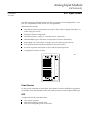
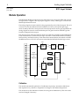
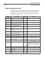
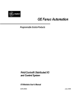
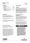
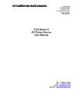
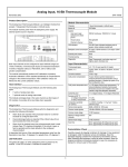
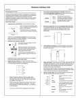
This Datasheet for the
IC670ALG620
RTD 4 Channel Isolated 3 or 4 Wire Input
http://www.qualitrol.com/shop/p-14496-ic670alg620.aspx
Provides the wiring diagrams and installation guidelines for this GE Field Control
module.
For further information, please contact Qualitrol Technical Support at
1-800-784-9385
[email protected]
10
Analog Input Module
IC670ALG620
GFK-1206D
June 1997
RTD Input Module
RTD Input Module (IC670ALG620)
datasheet GFK-1206D
The RTD Analog Input Module (IC670ALG620) accepts inputs from 4 independent 3-wire
and/or 4-wire platinum, nickel, nickel/iron, or copper RTDs.
Module features include:
H
Selectable resistance measurements in tenths of ohms, tenths of degrees Fahrenheit, or
tenths of degrees Celsius
H
H
H
H
H
H
H
Individual channel configuration
Selectable resistance ranges: 0 – 500 ohms and 0 – 3000 ohms
Selectable RTD input as resistance or temperature (Celsius or Fahrenheit)
Reportshigh/low, underrange/overrange, open wire and input short alarms.
Uses optional discrete inputs and outputs for status and control.
Two data acquisition rates based on 50 Hz and 60 Hz line frequencies
Configurable channel activation
46722
SLOT
4
3
2
1
Power Sources
No loop power is required for this module. The excitation current for the RTDs is provided by
the module, which automatically matches the excitation current to each configured RTD type.
LED
A single indicator shows module status:
H
H
H
ON: normal operation
Intermittent flashing: module fault
OFF: loss of backplane power or fatal fault
Analog Input Module
2
GFK-1206D
June 1997
RTD Input Module
Module Operation
The RTD Input Module accepts four inputs from three-wire or four-wire RTDs and converts
the input level to a digital value. Input spans support a variety of RTD types, as listed in the
Module Specifications section.
The analog/digital converter reads the voltage generated by each of the four inputs. The A/D
converter converts the differential measurement into a binary value (15 bits plus sign),
which is read by the block’s microprocessor. The microprocessor sets the gain required in the
analog/digital converter for each individual input. The gain is based on the RTD type that
has been configured for that input.
The microprocessor selects the input by means of a solid state, optically-coupled multiplexer.
Three measurements are made for each input: Excitation current, RTD resistance including
field wire drop, and field wire drop. From these three measurements, the module calculates
the RTD resistance. A DC/DC converter circuit isolates the field side from the logic circuits.
2.5V
Excitation
Current
Signal
+5 V
5V
DC/DC
Regulator
6.5V
–5 V
FLASH
Conditioning
and
Logic
Multiplexer
Opto
Micro–
processor
Serial Bus
A/D
2.5V
Reference
46723
Calibration
The module automatically performs A/D calibration at powerup. Automatic calibration is
then repeated every minute to compensate for changes in the ambient temperature.
The module stores the calibration constants for each gain in RAM memory. This data can be
read and changed if necessary.
Analog Input Module
3
GFK-1206D
June 1997
RTD Input Module
Host Interface
The RTD Input module has the following data types:
H
H
H
H
4 analog inputs (4 words)
32 bits of discrete input data for module and channel status (use of this data is optional)
8 bits of discrete output data for fault clearing to the module (also optional)
Analog output data defaults to a length of 0, and should NOT be used for most
applications.
A starting reference and length in the Bus Interface Unit (BIU) data tables for each data type
is selected during module configuration. Depending on the configuration that has been set
up for each RTD, the input data can be reported as tenths of ohms, tenths of degrees
Fahrenheit, or tenths of degrees Celsius.
This module exchanges data with a BIU in the same manner as other types of I/O
modules—it provides all its input data and status bits when requested by the BIU, and
receives fault-clearing commands from the BIU via its assigned output bits. Note that the
BIU can be configured not to send status data over the network.
The module can also be configured for “Group” data transfer with the BIU or with other
intelligent devices in the same Field Control station. Group data transfer, and the steps for
configuring it, are described in the Bus Interface Unit User’s Manual.
UnitsSelected
IntegerRanges
EngineeringUnits
Ranges
Tenths of Degrees
–32767 to +32767
–3276.7 to +3276.7
Tenths of Ohms
0 to 65535
0 Ohms to 6553.5 Ohms
Compatibility
This module must be used with a Bus Interface Unit revision 2.0 or later.
Analog Input Module
4
GFK-1206D
June 1997
RTD Input Module
Module Configuration Overview
Like other Field Control modules, the RTD Input module is usually configured from the Bus
Interface Unit, using a compatible hand-held programmer. The module will also accept
configuration data from the bus when used in a system that supports such configuration.
The table below summarizes configuration choices and defaults. The module will power up
with the default configuration settings. For configuration instructions, refer to the Bus
Interface Unit User’s Manual.
Description
Default
Choices
Analog Input
Data Length
Word length of the module’s analog input
data in the BIU’s analog input (AI) data table.
4
0–4
Analog Input
Data Reference
Starting offset for the module’s analog input
data in the BIU’s analog input (AI) table.
Discrete Input
Data Length
Bit length for the module’s optional status
data in the BIU’s discrete input (I) table.
Discrete Input
Data Reference
Starting offset for the module’s status data
in the BIU’s discrete input (I) table.
Discrete
Output Data
Length
Bit length for the module’s optional
fault-clearing bits in the BIU’s discrete
output (Q) table.
Discete Output
Data Reference
Starting offset for the module’s optional
fault-clearing bits in the BIU’s discete
output table.
Analog Output
Data Length
Word length for analog output data in the
BIU’s analog output (AQ) table. Should not
be used for most applications.
Analog Output
Data Reference
Starting offset for the module’s analog
output data in the BIU’s AQ table.
Line Frequency
Specifies the line frequency.
60 Hz
50 Hz, 60 Hz
Channel Active
Specifies if the channel should return data
and alarms. If a channel is “inactive” space
is still allocated for it.
Active
Inactive (off), Active (on)
Units
The conversion type for each RTD.
Deg C
tenths of ohms, tenths of degrees C, or
tenths of degrees F
RTD Type
The type of RTD used for each channel.
100 PT
385
10 PT, 25 PT, 25.5 PT 392, 100 PT 385, 100 PT
3902, 100 PT 392, 100 PT 3923, 100 PT 3916,
1K PT 375, 10 CU, 10 CU 427, 50 CU 427, 100
CU 427, 100 NI, 100 NI 618, 120 NI 672 604
NI/FE 518, 1K NI/FE 527, 500 Ohm, 3000
Ohm
Wire Type
The type of field wiring for each RTD.
3 Wire
3 Wire, 4 Wire
Alarm Low
The low alarm limit for the channel, in
engineering units.
–200
–32,768 to +32,767
Alarm High
The high alarm limit for the channel, in
engineering units.
800
–32,768 to +32,767
Resistance
An optional resistance adjustment, in tenths
of ohms.
0
0 to 3276.7
Module
Parameter
user selectable
32
0–32
user selectable
8
0–8
user selectable
0
0–4
user selectable
Analog Input Module
5
GFK-1206D
June 1997
RTD Input Module
Module Features
Channel Active
Each channel can be configured as either active or inactive.
If a channel is inactive, it is not scanned and a value of 0 is returned to the BIU.
If a channel is active, and the configured analog input data length is not long enough to
accommodate the data for a particular channel, the data for that channel is still processed,
since the response to a group command may be used to transmit that channel’s data to the
BIU.
Low Alarm Limit and High Alarm Limit
Each input channel can have a low alarm limit and a high alarm limit. If an input reaches
one of its limits, the module reports the actual value and sends the appropriate diagnostic bit
in the discrete input table of the BIU. Alarms do not stop the process or change the value of
the input.
Alarm limits can be set anywhere over the dynamic range of the signal. The range for each is
– 32,768 to +32,767. The high alarm limit must be greater than the low alarm limit. If alarm
reporting is not wanted, alarm limits can be set beyond the dynamic range of the signal so they
will never be activated.
Input Selection to Include RTD Type
Each input channel can have a different RTD type, selectable from a list of many different
RTDs.
If the actual RTD resistance does not match the defined type, an adjustment factor can be
configured in tenths of ohms.
Selection
Comments
Selection
Comments
Selection
Comments
10 PT
10 Ohm Platinum (PT)
100 PT 3916
100 Ohm Platinum,
α=.003916
100 NI 618
100 Ohm Nickel At 0C,
DIN43760, α=.00618
25 PT
25 Ohm Platinum IPTS-68
1K PT 375
1 KOhm Platinum,
α=.00375
120 NI 672
120 Ohm Nickel, at 0C,
α=.00672
25.5 PT 392
25.5 Ohm Platinum,
α=.00392 at 0C Lab Std
10 CU
10 Ohm Copper, at 25C,
IPTS-68
604NI/FE518
604 Ohm Nickel/Iron,at
0C, α=.00518
100 PT 385
100 Ohm Platinum,
DIN43760, α=.00385
9.035 CU 427
9.035 Ohm Copper, at
25C, α=.00427
IKNI/FE527
1 KOhm Nickel/Iron, at 70F,
α=.00527
100 PT 3902
100 Ohm Platinum,
α=.003902
50 CU 427
50 Ohm Copper,
α=.00427
500 OHM
Select UNITS of 1/10 Ohms
100 PT 392
100 Ohm Platinum,
α=.00392 IPTS-6 8
100 CU 427
100 Ohm Copper,
α=.00427
3000 OHM
Select UNITS of 1/10 Ohms
100 PT 3923
98.13 Ohm Platinum,
α=.003923
100 NI
100 Ohm Nickel, IPTS-68
Analog Input Module
6
GFK-1206D
June 1997
RTD Input Module
RTD Limits
The table below lists the ohms and temperature limits for different RTD types.
RTD Type
Low Ω
Limit
High Ω
Limit
Low
Temp. C
High
Temp. C
10 Ohm Copper @ 25C
6.13600
14.8200
–75.00
150.00
10 Ohm Platinum @ 25C
7.02000
37.2599
–70.00
1000.00
25 Ohm Platinum
4.14500
74.3089
–201.1111
537.77
100 Ohm Nickel
80.88890
147.7700
–40.00
140.00
1 KOhm Platinum, α=.00375
199.4880
2754.620
–200.00
500.00
100 Ohm Platinum α=.00385
27.01
389.936
–180.0
850.0
100 Ohm Platinum, α=.003902
93.5400
135.000
–17.7777
99.9999
100 Ohm Platinum IPTS68 (PA)
26.5
327.744
–200.0
630.0
100 Ohm Platinum SAMA-RC21-4 (PC)
26.5
311.874
–200.0
600.0
100 Ohm Platinum JISC-1604-’81
26.5
323.780
–200.0
620.0
25.5 Ohm Platinum Lab Std (PJ)
4.50
83.575
–200.0
630.0
9.035 Ohm Copper (CA)
6.05
16.400
–100.0
260.0
50 Ohm Copper (CB/2)
28.379
105.787
–100.0
260.0
100 Ohm Copper (CB)
56.757
211.574
–100.0
260.0
100 Ohm Nickel (NB)
69.520
223.221
–60.0
180.0
120 Ohm Nickel (NA)
66.600
380.310
–80.0
260.0
604 Ohm Nickel/Iron(FA)
372.789
1318.722
–100.0
204.0
1 KOhm Nickel/Iron(FB)
566.576
1985.891
–100.0
204.0
Analog Input Module
7
GFK-1206D
June 1997
RTD Input Module
Module Specifications
Module Characteristics
Number of Channels
Four 3-wire and/or 4-wire RTDs
Scan time
60 Hz: approximately 210 milliseconds per point
50 Hz: approximately 230 milliseconds per point,
Fault detection
Open RTD, input short, underrange, overrange, and high/low alarm
Normal mode rejection
60dB, at 50/60 Hz, 100% span
Common mode rejection
120 dB at 50/60Hz, 100 ohm imbalance
Common mode voltage
250 Vrms (350 VDC or peak AC)
Normal mode voltage
100% overrange DC or peak AC operational
28 VDC or peak AC maximum
Isolation:
User input to logic, user input to frame
ground.
1500 VAC for 1 minute, 250 VAC continuous.
Channel to Channel
250 VAC continuous.
Current drawn from BIU power supply
190 mA maximum
DigitalResolution
15 bits plus sign
Operating temperature range
0 to 55 Degrees C ambient
Channel Characteristics
RTD types
10, 25, 100, and 1000 ohm platinum
10 and 100 ohm copper
100, 50, and 120 ohm nickel
604 ohms and 1000 ohms nickel/iron
Resistanceranges
0 to 500 ohms
0 to 3000 ohms
Accuracy, at 25 C
RTD: +/–0.15% of reading, +/–0.3 to 0.5 degree Celsius, depending
on type
Temperature sensitivity (0 to 60C)
+/–0.004% of reading, +/–1.5µV per C referred to input
Maximum lead resistance
5 ohms per lead
Keying Locations
Optional keying locations for the RTD Module are:
KeyingLocations
A
n
B
C
D
n
E
F
G
H
n
J
n
K
Analog Input Module
8
GFK-1206D
June 1997
RTD Input Module
Field Wiring
The following illustration shows connections for 3-wire and 4-wire RTDs.
Required for
Calibration if no
RTD is Installed
4-Wire RTD
3-Wire RTD
Corresponding
Terminals
Source
Source
Source
7 8 15 16
In (+)
In (+)
In (+)
5 6 13 14
In (–)
In (–)
In (–)
3 4 11 12
Return
Return
Return
1 2 9 10
46724
No loop power is required for this module. The excitation current for the RTDs is provided
by the module, which automatically matches the excitation current to each configured RTD
type.
I/O Terminal Block Terminal Assignments
The Terminal Block with box terminals (IC670CHS002) has 25 terminals for each module. Each
accommodates one AWG #14 (avg 2.1mm2 cross section) to AWG #22 (avg 0.36mm2 cross
section) wire, or two wires up to AWG #18 (avg. 0.86mm2 cross section). When an external
jumper is used, wire capacity is reduced from AWG #14 (2.10mm2) to AWG #16 (1.32mm2).
The I/O Terminal Block with barrier terminals (IC670CHS001) has 18 terminals per module.
Each terminal can accommodate one or two wires up to AWG #14 (avg 2.1mm2 cross section).
The I/O Terminal Block with Connectors (IC670CHS003) has one 20-pin male connector per
module.
I/O Terminal Block with
Box Terminals
(IC670CHS002 and 102)
Source 4
In (+) 4
not used
In (–) 4
Return 4
not used
Source 2
In (+) 2
not used
In (–) 2
Return 2
not used
not used
not used
16
14
E8
12
10
E6
8
6
E4
4
2
E2
B2
B1
15
13
11
9
Source 3
In (+) 3
In (–) 3
Return 3
7
5
Source 1
In (+) 1
3
1
E1
A2
A1
In (–) 1
Return 1
not used
not used
not used
I/O Terminal Block with
Barrier Terminals
(IC670CHS001 and 101)
Source 4
16
In (+) 4
14
In (–) 4
12
Return 4
10
Source 2
8
In (+) 2
In (–) 2
6
Return 2
2
not used
B
4
15
11
Source 3
In (+) 3
In (–) 3
9
Return 3
7
Source 1
5
In (+) 1
3
In (–) 1
Return 1
not used
13
1
A
I/O Terminal Block with Wire
to Board Connectors
(IC670CHS003 and 103)
In (–) 3
In (–) 4
In (+) 3
In (+) 4
Source 3
Source 4
not used
not used
not used
not used
11 10
12 9
13 8
14 7
15 6
16 5
A2 4
A1 3
B2 2
B1 1
Return 4
Return 3
Source 2
Source 1
In (+) 2
In (+) 1
In (–) 2
In (–) 1
Return 2
Return 1
Ter minals E1, E2, E4, E6, and E8 are
electrically connected together, A1 and A2
ar e electrically connected together, B1
andB2 are electrically connected together.
46725
Analog Input Module
9
GFK-1206D
June 1997
RTD Input Module
Diagnostics
The RTD module performs diagnostics and provides the diagnostic data to the BIU using its
configured discrete input (I) references, starting at the configured reference offset.
The RTD sets the appropriate bit when a diagnostic condition is detected. The bit remains set
until cleared.
Circuit Diagnostics Bits (byte 0)
7 6 5 4 3 2 1 0
Circuit Diagnostics Bits (byte 2)
7 6 5 4 3 2 1 0
Low alarm for RTD 1
High alarm for RTD 1
Low alarm for RTD 2
High alarm for RTD 2
Low alarm for RTD 3
High alarm for RTD 3
Low alarm for RTD 4
High alarm for RTD 4
Open Wire, RTD 1
Open Wire, RTD 2
Open Wire, RTD 3
Open Wire, RTD 4
Shorted input, RTD 1
Shorted input, RTD 2
Shorted input, RTD 3
Shorted input, RTD 4
Circuit Diagnostics Bits (byte 3)
7 6 5 4 3 2 1 0
Circuit Diagnostics Bits (byte 1)
7 6 5 4 3 2 1 0
Input underrange, RTD 1
Input overrange, RTD 1
Input underrange, RTD 2
Input overrange, RTD 2
Input underrange, RTD 3
Input overrange, RTD 3
Input underrange, RTD 4
Input overrange, RTD 4
Wiring error, RTD 1
Wiring error, RTD 2
Wiring error, RTD 3
Wiring error, RTD 4
spare
spare
spare
spare
Clearing Faults and Alarms
Four optional discrete output bits in the BIU’s discrete output (Q) table can be used to clear
module faults and alarms.
Setting the discrete output bit for an RTD clears all diagnostic bits for that RTD that may be
set.
Output Command Bits to Clear Diagnostics
7 6 5 4 3 2 1 0
Clear All Faults on RTD 1
Clear All Faults on RTD 2
Clear All Faults on RTD 3
Clear All Faults on RTD 4
not used
not used
not used
not used