1
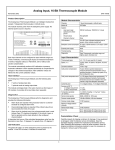
This Datasheet for the
IC670ALG320
Analog Output Current/Voltage 4 Pt. Grouped
http://www.cimtecautomation.com/parts/p-14494-ic670alg320.aspx
Provides the wiring diagrams and installation guidelines for this GE Field Control
module.
For further information, please contact Cimtec Technical Support at
1-866-599-6507
[email protected]
3
Analog Output Module
IC670ALG320
Current/Voltage Source Analog Output Module
GFK-0892H
June 1997
Current/Voltage Source Analog Output Module (IC670ALG320)
datasheet GFK-0892H
The Analog Output Module (IC670ALG320) provides a group of four current/voltageanalog
outputs. Each output channel provides a span of 4–20mA and 0–10V, which can be changed
to 0–20mA and 0–12.5 volts by adding jumper on the I/O Terminal Block. Default scaling is
0 to 20,000. Scaling can be changed in configuration to match the output used or to
engineering units.
46429
24 VDC 20.5mA MAX
SLOT
CURRENT SOURCE
ANALOG OUTPUT
4
3
2
1
PWR
24 VDC 20.5mA MAX
CURRENT SOURCE
ANALOG OUTPUT
Power Sources
The same 24 volt power supply used for the Bus Interface Unit can provide loop power to
the outputs in most cases. If module to module (or Bus Interface Unit) isolation is required,
separate power supply(s) must be used.
The most common application would have the loop supply local at the module, driving
multiple isolated transducers, isolated analog inputs, or differential analog inputs.
LED
An LED, visible through the transparent portion of the module top, indicates whether field
and backplane power are present.
t
Field Control Distributed I/O and Control System I/O Modules User’s Manual
GFK-0826G
3-1
Analog Output Module
2
GFK-0892H
June 1997
Current/Voltage Source Analog Output Module
Host Interface
The Current Source Analog Output Module has 4 words (8 bytes) of analog output data. A
Bus Interface Unit is required to provide this output data to the host and/or local
processor.
The module converts analog values from the host or local processor into output current.
Scaling for the module is performed by the Bus Interface Unit. Software Range Selection of 0
to 20mA and 4 to 20mA is available on a per-channel basis. Using the 0 to 20 mA range
requires the installation of an external wire jumper between JMP and RET.
The default scaling for this module is:
Eng Lo
Eng Hi
Int Lo
Int Hi
=
0
= 20,000
=
0
= 20,000
The default range is 0 to 20mA. The module is shipped with no wire jumper present. The
jumper must be installed to correspond to the module’s default range and scaling.
The 4–20mA range provides a fixed 4 milliamp offset (0mA = 4mA signal), with a 16mA
signal span. The 4mA offset remains as long as analog loop power is applied, even if the logic
power is off. Note that default outputs for loss of host communications require both
backplane power and analog field power.
A second output on each channel provides an uncalibrated voltage output. The 4 to 20mA
range corresponds to 0 to 10 volts. The 0 to 20 mA range corresponds to 0 to 12.5 volts. A
wire jumper is required for the 0 to 20mA range. Both voltage ranges have restricted load
current drive capability above 10 volts. Voltage can be used alone, or simultaneously with
current to drive meters or voltage input devices.
An OPEN WIRE diagnostic available per channel operates only on the current outputs. If
you are using only the voltage output of a channel, you should either disable the fault or
connect a dummy load of 250 to 800 ohms across the current terminals of the channel. An
OPEN WIRE fault will not affect the operation of the voltage output.
Output register values outside the capability of the module will drive the output to the
appropriate minimum or maximum level but will not generate a diagnostic fault.
Keying Locations
Optional keying locations for the Current Source Analog Output Module are:
KeyingLocations
A
n
3-2
t
B
C
n
D
E
F
G
H
Field Control Distributed I/O and Control System I/O Modules User’s Manual
GFK-0826G
J
K
n n
Analog Output Module
3
Current/Voltage Source Analog Output Module
GFK-0892H
June 1997
Scaling
The “Int” units on the HHM configuration screen correspond to actual desired output
current values, in microamps, provided the base terminal jumper corresponds to the module
range configuration. The Int unit values set in the configuration must be within the limits of
the range used. The module will operate with a range–jumper mismatch, but Int units
scaling will be invalid. The “Eng” units are the values supplied by the host.
Field Recalibration Using Scaling
Field recalibration can be accomplished by forcing the outputs to the “Eng Hi” and/or “Eng
Lo” calibration point values in the module configuration, reading the actual output
produced, and updating the configured values to the actual values. Usually, recalibrating the
high point only is sufficient. If the low point is done, it should be changed from the default
value of 0 volts or 4000 microAmps to get better accuracy. The following example shows a
two-point calibration for 0 to 10 volts:
1.
Set the analog output scaling for 0 to 10 volts output:
Eng lo
Eng hi
Internal lo
Internal hi
100
10,000
4,160
20,000
(mV)
(mV)
(corresponds to 100 mV)
(corresponds to 100 mV)
2.
Force the output to the low point value: 100 (= 0.100 volt)
3.
Read the output using an accurate meter on the output. For example, you might get a
value of 0.107 volts, instead of 100.
4.
Force the output to the high point value: 10000 (=10.000 volts)
5.
Read the output using an accurate meter on the output. For example, you might get a
value of 9.985 volts, instead of 10.000 volts.
6.
Change the scaling to the new calibrated values:
Eng lo
Eng hi
Internal lo
Internal hi
7.
107
9985
4160
20000
(reading in mv from step 3)
(reading in mv from step 5)
(microamps to yield voltage in step 2)
(microamps to yield voltage in step 4)
The voltage output is now calibrated to your meter, within the approximately 3-millivolt
resolution of the output.
Use the new Eng Hi and Eng Lo values as calibration points when repeating, or go back to
step 1 and begin again. The scaling affects both the voltage and current forms of the output
point, so only one can be recalibrated.
t
Field Control Distributed I/O and Control System I/O Modules User’s Manual
GFK-0826G
3-3
Analog Output Module
4
GFK-0892H
June 1997
Current/Voltage Source Analog Output Module
Module Operation
Four D/A converters provide simultaneous current and voltage outputs from each output
channel. Current output spans are 0–20 or 4–20 mA; voltage spans are 0–10 or 0–12.5
volts. All outputs are isolated from ground and logic, but are grouped on a common power
supply. Outputs can be isolated as a group from the rest of the system if a separate isolated
loop supply is used.
46430
To Other Circuits
A
36V
Terminals
I
.001mF
TB
24 V
D to A
Converter
EMI Filter
EMI Filter
MOV
30V
B
V
JMP
RET
10 Ohms
.001mF
Base
GND
To Other Circuits
Chassis
Each circuit provides simultaneous voltage and current outputs from the digital to analog
converter. All circuits share a common loop supply and return.
The current driver is a sourcing type. The low side of a load can be connected to RET, the
negative side of a 24 V loop supply, or a more negative point that can be up to 36 volts
negative with respect to the module 24 volt supply positive terminal.
Voltage output is relative to RET terminal, which is common to all circuits. The module’s 10
ohm resistor helps reduce ground loop circulating currents.
The operating range for an output can be changed to 0–20 mA, 0–12.5 volt by connecting
the JMP terminal to the RET terminal for that output, as illustrated above and on page
NO TAG of this datasheet.
The module contains MOV transient voltage suppressors, and RF bypass capacitors to the
module chassis. The chassis point is connected to the module case and the chassis ground
terminal on the module base. This should be grounded for best noise immunity.
Outputs default to minimum value upon initial powerup or loss of backplane power.
3-4
t
Field Control Distributed I/O and Control System I/O Modules User’s Manual
GFK-0826G
Analog Output Module
5
Current/Voltage Source Analog Output Module
GFK-0892H
June 1997
Module Specifications
Module Characteristics
Linearity, all ranges & outputs
Power supply range
24V Power input current
Standby (no output)
Operating
Module power dissipation
Temperaturecoefficient
1 LSB resolution value
20 to 29 volts, DC. 5% maximum ripple
Isolation to ground and logic
Input or channel to channel common mode
Current Drawn from BIU Power Supply
1500 VAC for 1 minute, 250 VAC continuous
None; single ended grouped out
51 mA maximum
80 mA typical
180 mA (including loop current),maximum
1.5 Watts, minimum, 4.3 Wattsmaximum
+/–.002% of value per degree C, typical,
+/–.005% of value per degree C, maximum
Output Characteristics
DigitalResolution
Current
Analog Resolution, LSB current
4 – 20 range
0 – 20 range
Output current range
JMP open
JMP to RET
Current load impedance
Open wire (current only)
Over–range
Output error, current (note 5)
Voltage
Analog Resolution, LSB voltage
0–10
0–12.5
Output voltage range
JMP open
JMP to RET
Voltage load impedance
Output error, voltage (note 5)
12 bits, typical
4.0microAmps,typical
5.0microAmps,typical
4 mA, minimum, 20mA maximum
.05 mA minimum, 20mA maximum (note 1)
0 Ohms minimum, 600 Ohms maximum (note 2)
800 load Ohms minimum (note 3)
20.000 mA minimum, 20.500 mA maximum
Ç 20µA Ç 0.1% of value, maximum
2.5 mV typical
3.125mVtypical
.02 Volts minimum, 10 Volts maximum (note 1)
.02 Volts minimum, 12.5 Voltsmaximum
2K Ohms minimum for 10V output, 5 K for 12.5V output
Ç 10mVÇ 0.25% of value, maximum
note 1: May limit or become non–linear below minimum values given, due to saturation of output drivers.
note 2: Minimum load should be 250 ohms if ambient exceeds 50 C. Valid over rated 18– 30 supply voltage.
Maximum load can be increased to 800 ohms if min. supply voltage is greater than 23.0 volts, including ripple.
note 3: Open wire occurs when there is insufficient compliance voltage to drive output to commanded value.
Therefore occurrence of open wire depends on combination of output load and current. The open wire warning
may occur continuously on a disconnected output, such as not used, or voltage used instead.
note 4: In the presence of severe RF interference (IEC 801–3, 10V/m), accuracy may be degraded to 1mA or
0.5V.
t
Field Control Distributed I/O and Control System I/O Modules User’s Manual
GFK-0826G
3-5
Analog Output Module
6
GFK-0892H
June 1997
Current/Voltage Source Analog Output Module
Field Wiring
The following illustration shows typical connections for this module.
Ret
Jmp
I
V
Isolated Current
Load 4–20mA
Twisted Pair
Ret
Jmp
I
V
Isolated Current
Load 0–20mA
Twisted Pair
Isolated Voltage
Load 0–10 Volts
Ret
Jmp
I
V
V
Twisted Pair
Differential Voltage com
Load 0–10 Volts
Local Loop
Power Supply
Ret
Jmp
I
V
V
Triad
Optional
Power
Supply
Ground
–
+
Common (“E”)
Terminals or
Auxiliary
Terminal Block
4” max.
Local Panel Gnd
B
A
46431
Instrumentation grade shielded twisted pair or 3 wire twisted (triad) wire should be used for
best noise immunity. The shield should be terminated at a local panel ground near the module.
The module local loop supply may be either floating or grounded, and may be shared with
other similar functions. All loads have a common return bus (RET) available at the module
for the negative side of the loads. This is internally connected through a 10-Ohm buffer
resistor to the supply negative side B terminal. Normally, only ungrounded loads are
recommended.
If a grounded load must be driven, a circulating ground loop current may be set up between
the load and ungrounded module supply. (This may reduce accuracy). The internal
resistance lessens the effect for small ground voltage differences.
CAUTION
The module may be damaged if high ground voltage differences occur due to
miswiring or high power surges.
Ordinarily no additional wiring to the RET bus is needed. However, if a low-impedance
ground is required to all devices, the proper way is to jumper any RET terminal to the power
B terminal at the module and ground the Loop supply externally.
3-6
t
Field Control Distributed I/O and Control System I/O Modules User’s Manual
GFK-0826G
Analog Output Module
7
GFK-0892H
June 1997
Current/Voltage Source Analog Output Module
If the module is installed on an I/O Terminal Block with Box Terminals or Barrier Terminals, an
Auxiliary Terminal Block may be used to provide additional wiring terminals. For the I/O
Terminal Block with Wire to Board Connectors, external connection points are usually preferred,
although an Auxiliary Terminal Block can be used.
Auxiliary Terminal Blocks have all terminals connected together internally. The Auxiliary
Terminal Block with box terminals has 13 terminals, each of which accommodates one AWG
# 14 (avg 2.1mm2 cross section) to AWG #22 (avg 0.36mm2 cross section) wire, or two wires up
to AWG #18 (avg. 0.86mm2 cross section). The Auxiliary Terminal Block with barrier terminals
has nine terminals, each of which can accommodate one or two wires up to AWG #14 (avg
2.1mm2 cross section).
The Panel Ground Shield from the Auxiliary Terminal Block to the panel should be AWG #14
wire, not longer than 4 inches (10cm).
I/O Terminal Block with
Box Terminals
(IC670CHS002 or 102)
RET 4
JMP 4
Common
RET 3
JMP 3
Common
RET 2
JMP 2
Common
RET 1
JMP 1
Common
DC–
DC–
16
14
E8
12
10
E6
8
6
E4
4
2
E2
B2
B1
15
13
11
9
7
5
3
1
E1
A2
A1
I4
V4
I3
V3
I2
V2
I1
V1
Common
DC+
DC+
I/O Terminal Block with
Barrier Terminals
(IC670CHS001 or 101)
RET 4
16
JMP 4
14
RET 3
JMP 3
12
10
RET 2
8
JMP 2
6
RET 1
4
JMP 1
2
DC–
B
15
I4
13
V4
11
I3
V3
I2
9
7
3
V2
I1
1
V1
5
A
DC+
Ter minals E1, E2, E4, E6, and E8 are
electrically connected togethe, A1 and A2
ar e electrically connected together, B1 and
B2 are electrically connected together.
t
Field Control Distributed I/O and Control System I/O Modules User’s Manual
GFK-0826G
I/O Terminal Block with Wire to
Board Connectors
(IC670CHS003 or 103)
I3
RET 3
V4
JMP 4
I4
RET 4
DC+
DC+
DC–
DC–
11 10
13 8
JMP 3
V3
RET 2
14 7
I2
15 6
A2 4
JMP 2
V2
RET 1
A1 3
I1
B2 2
JMP 1
V1
12 9
16 5
B1 1
46527
3-7