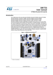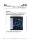
1
UM1904
User manual
Getting started with the X-CUBE-SUBG1 for Point-to-Point
communications based on Sub-1 GHz RF STM32 expansion board
Introduction
X-CUBE-SUBG1 is a demo application for the STM32 to build applications using the
Sub-1 GHz RF SPIRIT1 device. It is easily ported across different MCU families thanks to
STM32Cube.
This manual describes how to get started with the X-CUBE-SUBG1 software for Point-toPoint (P2P) applications, which represent the most straightforward protocol for bidirectional
wireless transmission of data packets from a transmitter to a receiver.
The software provides implementation examples for STM32 Nucleo platforms equipped with
the X-NUCLEO-IDS01A4 expansion board based on the SPSGRF-868 module or the
X-NUCLEO-IDS01A5 expansion board based on the SPSGRF-915 module.
The following demo examples are available for testing with the evaluation board:
•
WM-Bus wireless metering bus demo
•
Point-to-Point communication protocol demo
This document explains the Point-to-Point communication demo.
The software is based on STM32Cube technology and expands the STM32Cube-based
range of solutions.
June 2015
DocID027927 Rev 1
1/23
www.st.com
23
Contents
UM1904
Contents
1
2
3
STM32Cube . . . . . . . . . . . . . . . . . . . . . . . . . . . . . . . . . . . . . . . . . . . . . . . . 4
1.1
STM32Cube overview . . . . . . . . . . . . . . . . . . . . . . . . . . . . . . . . . . . . . . . . 4
1.2
STM32Cube architecture . . . . . . . . . . . . . . . . . . . . . . . . . . . . . . . . . . . . . . 4
X-CUBE-SUBG1 software expansion for STM32Cube . . . . . . . . . . . . . . 6
2.1
Overview . . . . . . . . . . . . . . . . . . . . . . . . . . . . . . . . . . . . . . . . . . . . . . . . . . 6
2.2
Architecture . . . . . . . . . . . . . . . . . . . . . . . . . . . . . . . . . . . . . . . . . . . . . . . . 6
2.3
Folders structure . . . . . . . . . . . . . . . . . . . . . . . . . . . . . . . . . . . . . . . . . . . . 7
2.4
APIs . . . . . . . . . . . . . . . . . . . . . . . . . . . . . . . . . . . . . . . . . . . . . . . . . . . . . . 8
Point-to-Point (P2P) demo firmware description . . . . . . . . . . . . . . . . . . 9
3.1
P2P application details . . . . . . . . . . . . . . . . . . . . . . . . . . . . . . . . . . . . . . . . 9
3.2
Application state diagram . . . . . . . . . . . . . . . . . . . . . . . . . . . . . . . . . . . . . . 9
3.3
SPIRIT1 packet handler overview . . . . . . . . . . . . . . . . . . . . . . . . . . . . . . .11
3.4
Transmit and receive packet structure . . . . . . . . . . . . . . . . . . . . . . . . . . . 12
3.4.1
3.5
3.6
4
2/23
Packet fields and their meaning . . . . . . . . . . . . . . . . . . . . . . . . . . . . . . . 13
User configuration . . . . . . . . . . . . . . . . . . . . . . . . . . . . . . . . . . . . . . . . . . 13
3.5.1
Selecting the SPIRIT1 expansion board platform . . . . . . . . . . . . . . . . . 13
3.5.2
Selecting packet handler . . . . . . . . . . . . . . . . . . . . . . . . . . . . . . . . . . . . 14
3.5.3
Setting low power mode . . . . . . . . . . . . . . . . . . . . . . . . . . . . . . . . . . . . 14
3.5.4
Setting radio configuration parameters . . . . . . . . . . . . . . . . . . . . . . . . . 15
3.5.5
Setting packet configuration parameters . . . . . . . . . . . . . . . . . . . . . . . . 15
3.5.6
Setting address of the nodes . . . . . . . . . . . . . . . . . . . . . . . . . . . . . . . . . 16
3.5.7
User defined commands and macros . . . . . . . . . . . . . . . . . . . . . . . . . . 16
Hardware description . . . . . . . . . . . . . . . . . . . . . . . . . . . . . . . . . . . . . . . . 16
3.6.1
STM32 Nucleo platform . . . . . . . . . . . . . . . . . . . . . . . . . . . . . . . . . . . . . 17
3.6.2
X-NUCLEO-IDS01Ax expansion board . . . . . . . . . . . . . . . . . . . . . . . . . 17
3.7
Software description . . . . . . . . . . . . . . . . . . . . . . . . . . . . . . . . . . . . . . . . . 18
3.8
Hardware setup . . . . . . . . . . . . . . . . . . . . . . . . . . . . . . . . . . . . . . . . . . . . 18
3.8.1
Hardware setup . . . . . . . . . . . . . . . . . . . . . . . . . . . . . . . . . . . . . . . . . . . 18
3.8.2
Setting up the board . . . . . . . . . . . . . . . . . . . . . . . . . . . . . . . . . . . . . . . 19
Acronyms and abbreviations . . . . . . . . . . . . . . . . . . . . . . . . . . . . . . . . . 20
DocID027927 Rev 1
UM1904
5
Contents
Reference . . . . . . . . . . . . . . . . . . . . . . . . . . . . . . . . . . . . . . . . . . . . . . . . . 21
5.1
6
Document conventions . . . . . . . . . . . . . . . . . . . . . . . . . . . . . . . . . . . . . . . 21
Revision history . . . . . . . . . . . . . . . . . . . . . . . . . . . . . . . . . . . . . . . . . . . 22
DocID027927 Rev 1
3/23
23
STM32Cube
UM1904
1
STM32Cube
1.1
STM32Cube overview
The STMCube™ initiative was designed by STMicroelectronics to help developers reduce
development effort, time and cost. STM32Cube covers the entire STM32 portfolio. Version
1.x includes:
•
STM32CubeMX, a GUI for generating C initialization code
•
a comprehensive embedded software platform for each series (e.g., STM32CubeF4 for
the STM32F4 series):
–
the STM32Cube HAL: STM32 abstraction layer embedded software for maximum
portability across the STM32 portfolio
–
a consistent set of middleware components such as RTOS, USB, TCP/IP and
graphics
–
all embedded software utilities with a full set of examples
Detailed information regarding STM32Cube is available on st.com at
http://www.st.com/stm32cube.
1.2
STM32Cube architecture
The STM32Cube firmware is built around three independent levels that can easily interact
with each other, as shown in the figure below.
Figure 1. Firmware architecture
4/23
DocID027927 Rev 1
UM1904
STM32Cube
Level 0 is divided into three sub-layers:
•
Board support package (BSP): offers a set of APIs for the hardware components on
the hardware boards (audio codec, IO expander, touchscreen, SRAM driver, LCD
drivers, etc.) and consists of two parts:
–
component: the driver relative to the external device on the board and not related
to the STM32, the component driver provides specific APIs to the BSP driver
external components and may be ported to any other board
–
BSP driver: links the component driver to a specific board and provides a set of
user-friendly APIs named BSP_FUNCT_Action() (e.g., BSP_LED_Init(),
BSP_LED_On(), etc.)
It is based on modular architecture, which is easily ported to any hardware by simply
implementing the low level routines.
•
•
Hardware Abstraction Layer (HAL): this layer provides the low level drivers and the
hardware interfacing methods to interact with the upper layers (application, libraries
and stacks).
It provides generic, multi-instance and function-oriented APIs which render user
applications unnecessary by providing ready to use processes. For example, for the
communication peripherals (I²S, UART, et.), it provides APIs to initialize and configure
the peripheral, manage data transfer based on polling, interrupts or DMA processes
and manage any communication errors that may raise.
The HAL Drivers APIs are split into two categories:
–
generic APIs with common and generic functions for the entire STM32 series
–
extension APIs with special functions for a specific family or part number
Basic peripheral usage examples: this layer covers the examples for the STM32
peripheral using the HAL and BSP resources.
Level 1 is divided into two sub-layers:
•
Middleware components: set of libraries covering USB Host and Device libraries,
STemWin, FreeRTOS, FatFS, LwIP and PolarSSL. Horizontal interaction between the
components on this layer is performed directly by calling the feature APIs, while the
vertical interaction with the low-level drivers is managed through specific callbacks and
static macros implemented in the library system call interface.
For example, the FatFs implements the disk I/O driver to access the microSD drive or
the USB Mass Storage Class.
•
Examples based on the middleware components: each middleware component
comes with one or more examples (or ‘applications’) demonstrating how it is used.
Integration examples that use several middleware components are also provided.
Level 2 provides comprehensive, real-time and graphical demonstrations of the middleware
service layer, the low-level abstraction layer and basic peripheral usage applications for
board-based functions.
DocID027927 Rev 1
5/23
23
X-CUBE-SUBG1 software expansion for STM32Cube
UM1904
2
X-CUBE-SUBG1 software expansion for STM32Cube
2.1
Overview
X-CUBE-SUBG1 is a software package that expands the functionality of STM32Cube.
The key features of the package are:
•
demo P2P communication example to transfer data from one node to another
•
middleware to build applications for WM-Bus (wireless metering bus)
•
easy portability across different MCU families thanks to STM32Cube
•
free user-friendly license terms
•
examples implementations available on board the X-NUCLEO-IDS01A4 (868 MHz) or
X-NUCLEO-IDS01A5 (915 MHz) connected onto a NUCLEO-L053R8 or NUCLEOF401RE
The following further be developments are possible by manipulating the software described
in this document:
•
automatic meter reading
•
home and building automation
•
WSN (wireless sensors network)
•
industrial monitoring and control
•
wireless fire and security alarm systems
The firmware partitioning between the STM32 on Nucleo boards and the SPIRIT1 device is
explained below:
STM32 MCU:
•
P2P application implementation
•
low power mode handling
•
interrupt services
SPIRIT1 role:
2.2
•
basic/STack modes
•
header, sync and trailer fields
•
encoding/decoding
•
sync detection
•
TX and RX FIFO
Architecture
This software is fully compliant with and expands on STM32Cube (see Section 1:
STM32Cube) to enable development of applications using X-NUCLEO-IDS01Ax (XNUCLEO-IDS01A4 or X-NUCLEO-IDS01A5) boards hosting the SPIRIT1 device module.
The software is based on STM32CubeHAL, the hardware abstraction layer for the STM32
microcontroller. The package extends STM32Cube by providing a board support package
(BSP) for the SPIRIT1 expansion board and some example firmware for P2P
communication.
6/23
DocID027927 Rev 1
UM1904
X-CUBE-SUBG1 software expansion for STM32Cube
The software layers used by the application software to access and use the SPIRIT1
expansion board are:
•
STM32Cube HAL layer: provides a generic, multi-instance set of APIs to interact with
the upper layers (the application, libraries and stacks). It consists of generic and
extension APIs based on a common architecture which allows other layers like the
middleware layer to function without specific Microcontroller Unit (MCU) hardware
configurations.
This structure improves library code reusability and guarantees easy device portability.
•
Board support package (BSP) Layer: includes the software to support the peripherals
on the STM32 Nucleo board (apart from the MCU). It is a set of APIs which provides a
programming interface for certain board-specific peripherals (LED, user button etc.).
The BSP firmware layer of the X-NUCLEO-IDS01Ax boards contains APIs for the
hardware components and consists of two parts:
a)
Component: this is the driver related to the external device on the board and not
related to the STM32 (see Section 1: STM32Cube). The SPIRIT1 BSP driver is
known as the firmware component.
The SPIRIT1 component driver provides specific APIs and can be ported to and
used on any board.
b)
BSP driver: enables the component driver to be linked to a specific board and
provides a set of user-friendly APIs.
•
Middleware: includes the WM-Bus, USB, touch sensing etc. libraries. There is no
middleware component For Point-to-Point applications as the demo/application layer
interacts with the SPIRIT1 link layer directly
•
Application layer: provides a Point-to-Point communication example which involves
sending a buffer from one node to another and acknowledgments using the features in
the SPIRIT1 link layer.
The figure below outlines the software architecture of the package.
Figure 2. X-CUBE-SUBG1 software architecture
2.3
Folders structure
This section provides an overview of the package folders structure. The next figure outlines
the architecture of the package.
DocID027927 Rev 1
7/23
23
X-CUBE-SUBG1 software expansion for STM32Cube
UM1904
Figure 3. X-CUBE-SUBG1 package folders structure
The following folders are included in the software package:
2.4
•
‘Documentation’: contains a compiled HTML file generated from the source code and
detailed documentation of the software components and APIs
•
‘Drivers’: contains the HAL drivers and the board-specific drivers for supported board
and hardware platforms, including those for the on-board components and the CMSIS
vendor-independent hardware abstraction layer for the Cortex-M processor series
•
‘Middlewares’: contains libraries for WM-Bus
•
‘Projects’: contains a sample application used for WM-Bus and P2P firmware examples
for the NUCLEO-L053R8 and NUCLEO-F401RE platforms with three development
environments (IAR Embedded Workbench for ARM, RealView Microcontroller
Development Kit (MDK-ARM), System Workbench for STM32 (SW4STM32)
•
‘Utilities’: this folder contains a ‘PC_software’ subfolder with a Windows PC utility for
WM-Bus usage and testing. Refer to the relevant documentation.
APIs
Detailed descritions of all the functions and parameters of the user APIs user can be found
in a compiled HTML file located inside the ‘Documentation’ folder.
8/23
DocID027927 Rev 1
UM1904
3
Point-to-Point (P2P) demo firmware description
Point-to-Point (P2P) demo firmware description
The following section explains how the demo firmware is implemented, the user settings
and configurations available and how to modify the firmware for other applications.
3.1
P2P application details
This P2P application is designed to operate thus:
1.
on each node (STM32 Nucleo board + SPIRIT1 expansion board), the user button on
the Nucleo board can be used to transmit a buffer to the other node.
2.
on receiving the signal, the receiver node LED lights up and an acknowledgment (ACK)
signal is returned the transmitter node
3.
on reception of the ACK signal, the transmitter node LED flashes four times and
switches off after a delay period
Figure 4. P2P application example
3.2
Application state diagram
This section explains how to run the demo example with the STM32 Nucleo boards.
The following figure shows the events and communication flow described above.
The SPIRIT1 remains by default in receive mode but changes to transmit mode when the
switch is pressed. Once transmission has terminated, the SPIRIT1 transceiver returns to its
default receive mode. On successful completion of the two-way communication (Command/
Ack), the MCU enters low-power mode.
To limit low-power mode current consumption, the LED is switched OFF by default. The LED
only glows for a short time.
The nodes in P2P have the same functionality and the address of each node is set in the
firmware via the user definitions.
DocID027927 Rev 1
9/23
23
Point-to-Point (P2P) demo firmware description
UM1904
Figure 5. Application state diagram when user presses Node1 button
If the user decides to press the switch on the other node, the functionality remains the same.
The Node will wake-up from low power mode, prepare the command for transmission and
send the data packet. Then it will wait for acknowledgment.
Figure 6. Application state diagram when user presses Node2 button
10/23
DocID027927 Rev 1
UM1904
Point-to-Point (P2P) demo firmware description
The following diagram shows both the transmit and receive states for data communication in
the firmware under low power modes.
Figure 7. Application state diagram
3.3
SPIRIT1 packet handler overview
This section explains the SPIRIT1 packet handler. Before on-air transmission, raw data is
arranged in a packet structure. The SPIRIT1 offers a highly flexible and fully programmable
packet: the structure of the packet, the number, the type, and the dimension of the fields
inside the packet depend on one of the possible configuration settings.
Through a suitable register, the user can choose from one of the formats shown in the
following tables:
Table 1. STack
Destination
Preamble Sync Length
address
Source
address
Control
Seq. no.
No ACK Payload CRC
Table 2. WM-Bus
Preamble
Sync
Payload
Postamble
Table 3. Basic
Preamble
Sync
Lenght
Destination
address
Control
Payload
CRC
A detailed description of the SPIRIT1 embedded packet handler is given in the SPIRIT1
datasheet.
Since the P2P communication requires the destination address of the receiving node, the
P2P demo is based on stack and basic packet handlers. The WM-Bus packet format is not
used and is beyond the scope of this example demonstration.
DocID027927 Rev 1
11/23
23
Point-to-Point (P2P) demo firmware description
UM1904
A basic comparison of the different packet handlers is given below.
Table 4. Packet handler feature comparison
Features
STack
WM-Bus
Basic
Destination address
filtering
Yes
No
Yes
Broadcast and
multicast
addressing
Yes
No
Yes
Source address filtering
Yes
No
No
Custom filtering
Yes
No
Yes
CRC filtering
Yes
No
Yes
Yes
No
No
Yes
No
No
Yes
No
No
(1)
LLP: automatic
acknowledgment
(1)LLP:
automatic
acknowledgment with
piggybacking
(1)LLP:
automatic
retransmission
1. Link layer protocol
3.4
Transmit and receive packet structure
This section explains the command and response packet structure.
Command packet features:
•
command with data
•
SPIRIT1 is able to handle 65535 bytes of data
•
avoid sending the command and data separately
•
user defines own command structure
•
user defines maximum data packet size
Figure 8. Command data structure packet information
Response packet features:
• data buffer is replied from the node
• tag contains the number associated with the command so the receiver can associate the
response with the specific command
12/23
DocID027927 Rev 1
UM1904
Point-to-Point (P2P) demo firmware description
Figure 9. Response packet structure
3.4.1
Packet fields and their meaning
Cmd Length: the basic command can be 1 byte long, however the user can have multiple
command bytes
Cmd Tag: a unique tag number is attached to each command issued from node and the
response must replicate this same number
Cmd Type: flag for identifying application level or network command
Commands: the actual command set sent from the source to destination, may include
parameters
Data Length: the size of the data packet length
Data buffer: the actual data associated with the command
3.5
User configuration
This section explains the configuration file (spirit1_appli.h) that can be modified by the user
according to the application.
Figure 10. User configuration
The different sections of the user configurable file are described below with the default
settings.
3.5.1
Selecting the SPIRIT1 expansion board platform
The user can select the desired SPIRIT1 expansion board platform by uncommenting the
macros shown below. Once the SPIRIT1 expansion board platform is selected, the
operating frequency is handled by firmware itself.
DocID027927 Rev 1
13/23
23
Point-to-Point (P2P) demo firmware description
UM1904
For example, if X-NUCLEO-IDS01A4 is selected as the SPIRIT1 expansion board, the
operating frequency selected by the firmware is 868 MHz.
Figure 11. Selecting SPIRIT1 expansion board platform in the firmware
3.5.2
Selecting packet handler
The user can select the desired features by uncommenting the relevant macros below. By
default, the SPIRIT1 works with BASIC packet handler.
SPIRIT1 will only use the STack packet handler if link layer features like auto ack,
piggybacking and auto retransmission are defined.
Figure 12. Selecting packet handler in the firmware
3.5.3
Setting low power mode
The P2P application supports low power mode, which is enabled by default. It is
implemented in such a way as to allow the MCU to either enter STOP mode or SLEEP
mode.
SPIRIT1 can be set to STANDBY mode to lower power consumption further.
14/23
DocID027927 Rev 1
UM1904
Point-to-Point (P2P) demo firmware description
Figure 13. Setting low power mode in the firmware
3.5.4
Setting radio configuration parameters
The user can set the radio parameter in the following section of the configuration file, even
though changing these settings is not recommended.
Figure 14. Setting setting radio configuration parameters in the firmware
3.5.5
Setting packet configuration parameters
The user can set the packet configuration in following part of code, even though changing
these settings is not recommended.
DocID027927 Rev 1
15/23
23
Point-to-Point (P2P) demo firmware description
UM1904
Figure 15. Setting packet configuration parameters in the firmware
3.5.6
Setting address of the nodes
Addresses can be set in following section of the system setup guide.
Figure 16. Address setting for nodes
3.5.7
User defined commands and macros
Below are the user defined commands and macros.
Figure 17. Setting user defined commands and macros in the firmware
3.6
Hardware description
This section describes the hardware components required for SPIRIT1-based applications.
For further details, refer to document UM1872: Getting started with the Sub-1 GHz
expansion board based on the SPSGRF-868 and SPSGRF-915 modules for STM32.
16/23
DocID027927 Rev 1
UM1904
3.6.1
Point-to-Point (P2P) demo firmware description
STM32 Nucleo platform
The STM32 Nucleo boards provide an affordable and flexible way for users to try out new
ideas and build prototypes with any STM32 microcontroller lines. The Arduino™
connectivity support and ST Morpho headers make it easy to expand the functionality of the
STM32 Nucleo open development platform with a wide choice of specialized expansion
boards. The STM32 Nucleo board does not require any separate probes as it integrates the
ST-LINK/V2-1 debugger/programmer. The STM32 Nucleo board comes with the STM32
comprehensive software HAL library together with various packaged software examples.
Information regarding STM32 Nucleo boards is available on st.com at
http://www.st.com/stm32nucleo.
Figure 18. STM32 Nucleo board
3.6.2
X-NUCLEO-IDS01Ax expansion board
The X-NUCLEO-IDS01Ax is a demonstration kit for evaluating the features and capabilities
of SPSGRF module based on the SPIRIT1 low data rate, low power sub-1 GHz transceiver
device.
The expansion board includes on board SPI EEPROM for saving parameters and user
interface LED.
Figure 19. X-NUCLEO-IDS1Ax expansion board
DocID027927 Rev 1
17/23
23
Point-to-Point (P2P) demo firmware description
UM1904
Information regarding the X-NUCLEO-IDS01A4 and X-NUCLEO-IDS01A5 STM32
expansion boards is available on st.com at http://www.st.com/x-nucleo.
Figure 20. X-NUCLEO-IDS1Ax expansion board plugged to STM32 Nucleo board
3.7
Software description
The following software components establish the development environment for creating
applications using the STM32 Nucleo equipped with a SPIRIT1 expansion board:
3.8
•
X-CUBE-SUBG1: an STM32Cube expansion for SPIRIT1 application development.
The X-CUBE-SUBG1 firmware and relative documentation is available on st.com.
•
development tool-chain and compiler: the STM32Cube expansion software supports
the following environments:
–
IAR Embedded Workbench for ARM® (EWARM) toolchain + ST-Link
–
RealView Microcontroller Development Kit (MDK-ARM) toolchain + ST-LINK
–
System Workbench for STM32 (SW4STM32) + ST-LINK
Hardware setup
This section describes the hardware and software setup procedures and the corresponding
system setup.
3.8.1
Hardware setup
The following hardware components are needed per node:
18/23
1.
a STM32 Nucleo Development platform (suggested order code: either NUCLEOF401RE or NUCLEO-L053R8)
2.
a SPIRIT1 expansion board (order code: X-NUCLEO-IDS01A4 (868 MHz) or XNUCLEO-IDS01A5 (915 MHz))
3.
a USB type A to Mini-B USB cable to connect the STM32 Nucleo to the PC
DocID027927 Rev 1
UM1904
Point-to-Point (P2P) demo firmware description
Two nodes are needed to replicate the P2P demo.
3.8.2
Setting up the board
Follow these steps to set up the board:
1.
check that a jumper is present on the J1 connector. This jumper provides the required
voltage to the devices on the board
2.
connect the X-NUCLEO-IDS01Ax to the Nucleo board from the top as shown in
Figure 20
3.
power the Nucleo board using the Mini-B USB cable
4.
program the firmware in the STM32 on the Nucleo board using the firmware example
provided
5.
press the reset button on the Nucleo board
6.
the demonstration kit is ready to be used
DocID027927 Rev 1
19/23
23
Acronyms and abbreviations
4
UM1904
Acronyms and abbreviations
Table 5. Acronyms and abbreviations
Acronym
AMR
Automatic meter reading
BSP
Board support package. Generally referred to the hardware interface layer.
EEPROM
Electrically erasable programmable read only memory
GHz
Giga Hertz
GUI
Graphical user interface
HAL
Hardware abstraction layer
LED
Light emitting diode
MCU
Microcontroller unit
P2P
Point-to-Point communication
RF
Radio frequency communication
SPI
Serial peripheral interface
USB
Universal serial bus
WM-Bus
WSN
20/23
Description
Wireless metering bus
Wireless sensors network
DocID027927 Rev 1
UM1904
5
5.1
Reference
Reference
1.
SPIRIT1 device datasheet
2.
SPSGRF module datasheet
3.
STM32 and Nucleo board datasheets
4.
UM1872: Getting started with the Sub-1 GHz expansion board based on the SPSGRF868 and SPSGRF-915 modules for STM32
Document conventions
1.
X-NUCLEO-IDS01Ax: refers to the SPIRIT1 module SPSGRF expansion board (XNUCLEO-IDS01A4/ X-NUCLEO-IDS01A5)
2.
SPIRIT1 module expansion boards: refers to X-NUCLEO-IDS01Ax (x = 4, 5) as
explained above
3.
STM32 Nucleo board: refers to NUCLEO-L053R8 or NUCLEO-F401RE unless
otherwise specified
4.
the firmware described in this document is developed and tested using the NUCLEOL053R8 or NUCLEO-F401RE and X-NUCLEO-IDS01Ax (x = 4, 5) boards; the demo
firmware is easily ported to other NUCLEO or SPIRIT1 boards by making changes to
the BSP layer
5.
Node: refers to the combination of the STM32 Nucleo board and X-NUCLEO-IDS01Ax
expansion board in a connected network
DocID027927 Rev 1
21/23
23
Revision history
6
UM1904
Revision history
Table 6. Document revision history
22/23
Date
Revision
10-Jun-2015
1
Changes
Initial release.
DocID027927 Rev 1
UM1904
IMPORTANT NOTICE – PLEASE READ CAREFULLY
STMicroelectronics NV and its subsidiaries (“ST”) reserve the right to make changes, corrections, enhancements, modifications, and
improvements to ST products and/or to this document at any time without notice. Purchasers should obtain the latest relevant information on
ST products before placing orders. ST products are sold pursuant to ST’s terms and conditions of sale in place at the time of order
acknowledgement.
Purchasers are solely responsible for the choice, selection, and use of ST products and ST assumes no liability for application assistance or
the design of Purchasers’ products.
No license, express or implied, to any intellectual property right is granted by ST herein.
Resale of ST products with provisions different from the information set forth herein shall void any warranty granted by ST for such product.
ST and the ST logo are trademarks of ST. All other product or service names are the property of their respective owners.
Information in this document supersedes and replaces information previously supplied in any prior versions of this document.
© 2015 STMicroelectronics – All rights reserved
DocID027927 Rev 1
23/23
23