1
P321-E122-04EN
PRIMEPOWER
PRIMEPOWER200
PRIMEPOWER400
PRIMEPOWER600
Preface
This manual explains the features, functions, installation and additions to the PRIMEPOWER200,
PRIMEPOWER400 and PRIMEPOWER600 servers and is intended for experienced users with a basic knowledge
of UNIX and UNIX servers.
This preface describes the following items:
SAFE OPERATION
Introduction to Chapters
Related Manuals
Warning Message Conventions
Operating Environment
Prohibited Uses
FCC Class A Notice
Trademarks
Copyright
SAFE OPERATION
Using This Manual
This manual contains important information regarding the use and handling of this product. Read
this manual thoroughly. Pay special attention to the section "Important Warnings". Use the product
according to the instructions and information available in this manual.
FUJITSU makes every efforts to prevent users and bystanders from being injured or from suffering
damage to their property. Use the product according to this manual.
i
Introduction to Chapters
The structure of this manual is as follows:
CHAPTER 1 Features of the PRIMEPOWER Servers
Chapter 1 gives an overview of the features of the PRIMEPOWER of servers.
CHAPTER 2 PRIMEPOWER200 Pedestal Server
Chapter 2 gives an overview of the PRIMEPOWER200 Pedestal Server, names and functions of
parts, preparations for use, and expansion.
CHAPTER 3 PRIMEPOWER200 Rackmount (4U) Server
Chapter 3 gives an overview of the PRIMEPOWER200 Rackmount (4U) Server, names and
functions of parts, preparations for use, and expansion.
CHAPTER 4 PRIMEPOWER400 Pedestal Server
Chapter 4 gives an overview of the PRIMEPOWER400 Pedestal Server, names and functions of
parts, preparations for use, and expansion.
CHAPTER 5 PRIMEPOWER400 Rackmount (4U) Server
Chapter 5 gives an overview of the PRIMEPOWER400 Rackmount (4U) Server, names and
functions of parts, preparations for use, and expansion.
CHAPTER 6 PRIMEPOWER400 Rackmount (10U) Server
Chapter 6 gives an overview of the PRIMEPOWER400 Rackmount (10U) Server, names and
functions of parts, preparations for use, and expansion.
CHAPTER 7 PRIMEPOWER600 Pedestal Server
Chapter 7 gives an overview of the PRIMEPOWER600 Pedestal Server, names and functions of
parts, preparations for use, and expansion.
CHAPTER 8 PRIMEPOWER600 Rackmount (10U) Server
Chapter 8 gives an overview of the PRIMEPOWER600 Rackmount (10U) Server, names and
functions of parts, preparations for use, and expansion.
CHAPTER 9 Expansion Disk Cabinet
Chapter 9 gives an overview of the Expansion Disk Cabinet, names and functions of parts,
installation, configuration of the disk drive bay, and hot-swapping of redundant components.
CHAPTER 10 Expansion File Unit Type-2
Chapter 10 gives an overview of the Expansion File Unit Type-2, names and functions of parts,
installation, configuration of the disk drive bay, and hot-swapping of redundant components.
CHAPTER 11 Internal I/O Units
Chapter 11 gives an overview of how to use the various internal I/O devices.
CHAPTER 12 RCI Commands
Chapter 12 gives an overview of the RCI commands.
CHAPTER 13 Troubleshooting
Chapter 13 helps the user isolate the causes of system failures, and suggests possible solutions.
CHAPTER 14 Glossary
Chapter 14 explains the meaning of the various specialized terms used in this manual.
ii
Related Manuals
The following manuals contain related material:
"Enhanced Support Facility User’s Guide"
"Enhanced Support Facility Installation Guide"
"Enhanced Support Facility Machine Administration Instructions"
Warning Message Conventions
A warning message consists of a label and statements. The following warning message types are displayed to
prevent users and bystanders from being injured or from suffering property damage.
WARNING
This indicates a hazardous situation that could result in death or serious injury if the user does not
perform the procedure correctly.
CAUTION
This indicates a hazardous situation that could result in minor or moderate personal injury if the user
does not perform the procedure correctly. It also indicates that damage to the product or other
property may occur of the user does not perform the procedure correctly.
IMPORTANT
This indicates information that could help the user use the product more efficiently.
How warning messages are displayed in the manual
Each warning message is accompanied by an indicator of the warning type, followed by a more detailed
explanation.
(Example)
Electric shock/fire
WARNING
If you detect an abnormality such as heat build-up, smoke or foul
odor, immediately turn the AC main line switch OFF, or disconnect
the power cable, and contact a service engineer. Failure to do so
might cause electric shock or fire.
Important warning messages are summarized under "Important Warnings".
iii
Operating Environment
This product has been designed and produced to be used safely by general users in a general office environment.
When using this product, observe the installation and handling precautions described in this manual.
Prohibited Uses
This Product is designed, developed and manufactured as contemplated for general use, including without
limitation, general office use, personal use and household use, but is not designed, developed and manufactured as
contemplated for use accompanying fatal risks or dangers that, unless extremely high safety is secured, could lead
directly to death, personal injury, severe physical damage or other loss (hereinafter "High Safety Required Use"),
including without limitation, nuclear power core control, airplane control, air traffic control, mass transport
operation control, life support, weapon launching control. You shall not use this Product without securing the
sufficient safety required for the High Safety Required Use. Hence, if these products are used in such hazardous
environments, FUJITSU LIMITED and SUN MICROSYSTEMS, INC. Do not warrant them at all. If you wish to
use this Product for High Safety Required Use, please consult with our sale person in charge before such use.
Documents produced by FUJITSU may contain technology controlled under the Foreign Exchange and Foreign
Trade Control Law of Japan. Those documents containing such technology should not be exported from Japan or
transferred to anyone other than residents of Japan without first obtaining license from the Ministry of
International Trade and Industry of Japan in accordance with the above law.
FCC Class A Notice
CAUTION
This equipment has been tested and found to comply with the limits for a Class digital
device, pursuant to Part 15 of the FCC Rules. These limits are designed to provide
reasonable protection against harmful interference when the equipment is operated in
a commercial environment. This equipment generates, uses, and can radiate radio
frequency energy, and if not installed and used in accordance with the instruction
manual, may cause harmful interference to radio communications. Operation of this
equipment in a residential area is likely to cause harmful interference in which case
the user will be required to correct the interference at his own expense.
This product is compliant with harmonics guidelines.
Trademarks
Solaris is a trademark of Sun Microsystems Inc.
SPARC64 is a registered trademark or trademark of SPARC International, Inc. in the United States and other
countries, under license by Fujitsu Ltd.
iv
Copyright
All rights reserved. This product and related documentation are protected by copyright and distributed under
licenses already restricting its use, copying, distribution, and recompilation. No part of this product or related
documentation may be reproduced in any form by any means without prior written authorization of Fujitsu
Limited and its licensors, if any.
The contents of this manual may be revised without prior notice.
All Rights Reserved, Copyright (c) FUJITSU LIMITED 2001
v
Safety Cautions
Important Warnings
The following types of warnings are found in this manual:
WARNING
This indicates a hazardous situation could result in death or serious injury if the
user does not perform the procedure correctly.
Normal Operation Warnings
task
Warning
Electric shock/fire Do not deform, damage or strip the power cable.
Doing so might cause electric shock or fire.
Electric shock/fire If you detect an abnormality such as heat build-up,
smoke or foul odor, immediately turn the main line
switch OFF, or disconnect the power cable, and
contact a service engineer. Failure to do so might
cause electric shock or fire.
vi
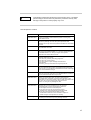
CAUTION
This indicates a hazardous situation that could result in minor or moderate
personal injury if the user does not perform the procedure correctly. Also,
damage to the product or other property may occur.
Normal Operation Cautions
Task
Caution
Data destruction:
Pressing the RESET switch while the system is running may
cause data to be lost.
Data destruction:
Install "Enhanced Support Facility" before operating the system.
Without this package, incorrect front panel operations and
hardware errors may cause the system to shutdown or cause data
to be lost.
Data destruction:
Pressing the REQUEST switch while the system is running
may cause data to be lost.
Data destruction:
Do not turn the console (unit connected to serial port) on
after turning the PRIMEPOWER on, or turn the console off while
the PRIMEPOWER is on. Doing so might cause system
malfunction and cause data to be lost.
Data destruction:
Before turning the power off, check the following points.
Otherwise, data may be lost.
Are there any currently executing programs?
Are there any current users?
Are floppy disks or tape cartridges still inserted in
their drives?
If necessary, back up files before turning the power off.
Data destruction:
If improper commands are used at the ok prompt, data may be
lost. If you need to use any other commands except those given
in this manual, you should fully understand the function and usage
of the command before using it.
Data destruction:
Except in any emergency, never turn the AC main line switch or
disconnect the power cable while the PRIMEPOWER is turned on.
If you do, data in the disk drive may be lost.
Data destruction:
Before you eject a floppy disk, be sure to either execute
the Solaris eject command, or perform eject operation in the
application you are using. Failure to do so might cause data to be
lost. Also, do not eject a floppy disk while the access
LED is on. Doing so may damage the disk.
Unit damage/
Data destruction:
Pay attention to the following points when handling the
hard disk units. If these precautions are not observed,
the magnetic disk unit may be damaged or data lost.
Do not subject the unit to exceeds impact.
Do not bring the unit near to equipment (motors,
speakers, etc.) that generate strong magnetic fields.
Do not store the unit at locations likely to cause
condensation inside the unit or at locations subject to
sudden changes in temperature or humidity.
Unit damage:
Do not connect I/O units to the maintenance port.
Connecting I/Os to the SCF port may damage this unit.
vii
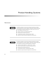
Product Handling Cautions
Maintenance
WARNING
The following operations on this product and options provided by FUJITSU
should be performed by a service engineer, and should not be performed by the
user. Otherwise, the user may create the risk of electric shock, injury or fire.
New installation and moving of units
Removal of the front, rear and side panel covers
Mounting/removal of built-in option units
Connection/disconnection of external interface cables
Maintenance (repair and periodic diagnosis and maintenance)
CAUTION
The following operations on this product and options provided by FUJITSU
should be performed by a service engineer, and should not be performed by the
user. Otherwise, the user may cause the products to malfunction.
Unpacking of option adapter, etc. delivered to the customer
Removal of the front panel, rear panel and side panel covers
Mounting/removal of built-in option units
Connection/disconnection of external interface cables
Maintenance (repair and periodic diagnosis and maintenance)
viii
Remodeling and Recycling of This Product
If this product is remodeled with secondhand parts,overhauled, or recycled as is, users and bystanders may be
injured and property damaged unexpectedly.
ix
CONTENTS
CHAPTER 1
Features of the PRIMEPOWER Servers
1
CHAPTER 2
PRIMEPOWER200 Pedestal Server
3
2.1
Overview
4
2.2
Names and Functions of Parts
: : : : : : : : : : : : : : : : : : : : : : : : : : : : : : : : : : : : : :
: : : : : : : : : : : : : : : : : : : : : : : : : : : :
5
: : : : : : : : : : : : : : : : : : : : : : : : : : : : : : : : : : :
5
2.2.1
Front side
2.2.2
Control panel
2.2.3
Rear side
2.3
: : : : : : : : : : : : : : : : : : : : : : : : : : : : : : : : :
6
: : : : : : : : : : : : : : : : : : : : : : : : : : : : : : : : : : :
8
Preparations for Use
: : : : : : : : : : : : : : : : : : : : : : : : : : : : : : : : :
2.3.1
Installation notes
2.3.2
Installation specifications
2.3.3
Connecting the console
2.3.4
: : : : : : : : : : : : : : : : : : : : : : : : : : : : : : :
10
10
: : : : : : : : : : : : : : : : : : : : : : : : : : :
12
: : : : : : : : : : : : : : : : : : : : : : : : : : : :
14
Turning the power on
: : : : : : : : : : : : : : : : : : : : : : : : : : : : :
14
2.3.5
Turning the power off
: : : : : : : : : : : : : : : : : : : : : : : : : : : : :
16
2.3.6
Installing the Enhanced Support Facility package
2.3.7
How to enable/disable the break signal
2.3.8
LAN expansion note
: : : : : : : : : : : : : : :
17
: : : : : : : : : : : : : : : : : : : :
18
: : : : : : : : : : : : : : : : : : : : : : : : : : : : :
19
i
2.4
CHAPTER 3
: : : : : : : : : : : : : : : : : : : : : : : : : : : : : :
2.4.1
Adding CPU modules
2.4.2
Adding memory modules
2.4.3
Adding hard disk drives
2.4.4
Adding PCI cards
: : : : : : : : : : : : : : : : : : : : : : : : : : : : :
20
21
: : : : : : : : : : : : : : : : : : : : : : : : : : :
21
: : : : : : : : : : : : : : : : : : : : : : : : : : : :
22
: : : : : : : : : : : : : : : : : : : : : : : : : : : : : : :
24
PRIMEPOWER200 Rackmount (4U) Server
25
3.1
Overview
26
3.2
Names and Functions of Parts
: : : : : : : : : : : : : : : : : : : : : : : : : : : : : : : : : : : : : :
: : : : : : : : : : : : : : : : : : : : : : : : : : : :
27
: : : : : : : : : : : : : : : : : : : : : : : : : : : : : : : : : : :
27
3.2.1
Front side
3.2.2
Control panel
3.2.3
Rear side
3.3
: : : : : : : : : : : : : : : : : : : : : : : : : : : : : : : : :
27
: : : : : : : : : : : : : : : : : : : : : : : : : : : : : : : : : : :
30
Preparations for Use
: : : : : : : : : : : : : : : : : : : : : : : : : : : : : : : : :
3.3.1
Installation notes
3.3.2
Installation specifications
3.3.3
Connecting the console
3.3.4
: : : : : : : : : : : : : : : : : : : : : : : : : : : : : : :
31
31
: : : : : : : : : : : : : : : : : : : : : : : : : : :
33
: : : : : : : : : : : : : : : : : : : : : : : : : : : :
34
Turning the power on
: : : : : : : : : : : : : : : : : : : : : : : : : : : : :
35
3.3.5
Turning the power off
: : : : : : : : : : : : : : : : : : : : : : : : : : : : :
37
3.3.6
Installing the Enhanced Support Facility package
3.3.7
How to enable/disable the break signal
3.3.8
LAN expansion note
3.4
ii
Expanding the Server Unit
Expanding the Server Unit
: : : : : : : : : : : : : : :
38
: : : : : : : : : : : : : : : : : : : :
39
: : : : : : : : : : : : : : : : : : : : : : : : : : : : :
40
: : : : : : : : : : : : : : : : : : : : : : : : : : : : : :
41
3.4.1
Adding power supply units
3.4.2
Adding CPU modules
3.4.3
Adding memory modules
3.4.4
Adding hard disk drives
3.4.5
Adding PCI cards
: : : : : : : : : : : : : : : : : : : : : : : : : :
42
: : : : : : : : : : : : : : : : : : : : : : : : : : : : :
42
: : : : : : : : : : : : : : : : : : : : : : : : : : :
43
: : : : : : : : : : : : : : : : : : : : : : : : : : : :
43
: : : : : : : : : : : : : : : : : : : : : : : : : : : : : : :
44
CONTENTS
CHAPTER 4
PRIMEPOWER400 Pedestal Server
45
4.1
Overview
46
4.2
Names and Functions of Parts
: : : : : : : : : : : : : : : : : : : : : : : : : : : :
47
: : : : : : : : : : : : : : : : : : : : : : : : : : : : : : : : : : :
47
4.2.1
Front side
4.2.2
Control panel
4.2.3
Rear side
4.3
: : : : : : : : : : : : : : : : : : : : : : : : : : : : : : : : :
48
: : : : : : : : : : : : : : : : : : : : : : : : : : : : : : : : : : :
51
Preparations for Use
: : : : : : : : : : : : : : : : : : : : : : : : : : : : : : : : :
4.3.1
Installation notes
4.3.2
Installation specifications
4.3.3
Connecting the console
4.3.4
: : : : : : : : : : : : : : : : : : : : : : : : : : : : : : :
52
52
: : : : : : : : : : : : : : : : : : : : : : : : : : :
53
: : : : : : : : : : : : : : : : : : : : : : : : : : : :
55
Turning the power on
: : : : : : : : : : : : : : : : : : : : : : : : : : : : :
55
4.3.5
Turning the power off
: : : : : : : : : : : : : : : : : : : : : : : : : : : : :
57
4.3.6
Installing the Enhanced Support Facility package
4.3.7
How to enable/disable the break signal
4.3.8
LAN expansion note
4.4
CHAPTER 5
: : : : : : : : : : : : : : : : : : : : : : : : : : : : : : : : : : : : : :
Expanding the Server Unit
: : : : : : : : : : : : : : :
58
: : : : : : : : : : : : : : : : : : : :
59
: : : : : : : : : : : : : : : : : : : : : : : : : : : : :
60
: : : : : : : : : : : : : : : : : : : : : : : : : : : : : :
61
4.4.1
Adding power supply units
4.4.2
Adding CPU modules
4.4.3
Adding memory modules
4.4.4
Adding hard disk drives
4.4.5
Adding PCI cards
: : : : : : : : : : : : : : : : : : : : : : : : : :
62
: : : : : : : : : : : : : : : : : : : : : : : : : : : : :
63
: : : : : : : : : : : : : : : : : : : : : : : : : : :
63
: : : : : : : : : : : : : : : : : : : : : : : : : : : :
64
: : : : : : : : : : : : : : : : : : : : : : : : : : : : : : :
65
PRIMEPOWER400 Rackmount (4U) Server
67
5.1
Overview
68
5.2
Names and Functions of Parts
: : : : : : : : : : : : : : : : : : : : : : : : : : : : : : : : : : : : : :
: : : : : : : : : : : : : : : : : : : : : : : : : : : :
68
: : : : : : : : : : : : : : : : : : : : : : : : : : : : : : : : : : :
69
5.2.1
Front side
5.2.2
Control panel
5.2.3
Rear side
: : : : : : : : : : : : : : : : : : : : : : : : : : : : : : : : :
69
: : : : : : : : : : : : : : : : : : : : : : : : : : : : : : : : : : :
72
iii
5.3
Installation notes
5.3.2
Installation specifications
5.3.3
Connecting the console
5.3.4
: : : : : : : : : : : : : : : : : : : : : : : : : : : : : : :
73
73
: : : : : : : : : : : : : : : : : : : : : : : : : : :
75
: : : : : : : : : : : : : : : : : : : : : : : : : : : :
76
Turning the power on
: : : : : : : : : : : : : : : : : : : : : : : : : : : : :
77
5.3.5
Turning the power off
: : : : : : : : : : : : : : : : : : : : : : : : : : : : :
78
5.3.6
Installing the Enhanced Support Facility package
5.3.7
How to enable/disable the break signal
5.3.8
LAN expansion note
Expanding the Server Unit
: : : : : : : : : : : : : : :
80
: : : : : : : : : : : : : : : : : : : :
80
: : : : : : : : : : : : : : : : : : : : : : : : : : : : :
81
: : : : : : : : : : : : : : : : : : : : : : : : : : : : : :
82
5.4.1
Adding power supply units
5.4.2
Adding CPU modules
5.4.3
Adding memory modules
5.4.4
Adding hard disk drives
5.4.5
Adding PCI cards
: : : : : : : : : : : : : : : : : : : : : : : : : :
84
: : : : : : : : : : : : : : : : : : : : : : : : : : : : :
85
: : : : : : : : : : : : : : : : : : : : : : : : : : :
86
: : : : : : : : : : : : : : : : : : : : : : : : : : : :
86
: : : : : : : : : : : : : : : : : : : : : : : : : : : : : : :
87
PRIMEPOWER400 Rackmount (10U) Server
89
6.1
Overview
90
6.2
Names and Functions of Parts
: : : : : : : : : : : : : : : : : : : : : : : : : : : : : : : : : : : : : :
: : : : : : : : : : : : : : : : : : : : : : : : : : : :
91
: : : : : : : : : : : : : : : : : : : : : : : : : : : : : : : : : : :
91
6.2.1
Front side
6.2.2
Control panel
6.2.3
Rear side
6.3
iv
: : : : : : : : : : : : : : : : : : : : : : : : : : : : : : : : :
5.3.1
5.4
CHAPTER 6
Preparations for Use
: : : : : : : : : : : : : : : : : : : : : : : : : : : : : : : : :
92
: : : : : : : : : : : : : : : : : : : : : : : : : : : : : : : : : : :
94
Preparations for Use
: : : : : : : : : : : : : : : : : : : : : : : : : : : : : : : : :
6.3.1
Installation notes
6.3.2
Installation specifications
6.3.3
Connecting the console
6.3.4
6.3.5
: : : : : : : : : : : : : : : : : : : : : : : : : : : : : : :
96
96
: : : : : : : : : : : : : : : : : : : : : : : : : : :
99
: : : : : : : : : : : : : : : : : : : : : : : : : : : :
100
Turning the power on
: : : : : : : : : : : : : : : : : : : : : : : : : : : : :
101
Turning the power off
: : : : : : : : : : : : : : : : : : : : : : : : : : : : :
103
CONTENTS
6.3.6
Installing the Enhanced Support Facility package
6.3.7
How to enable/disable the break signal
6.3.8
LAN expansion note
6.4
CHAPTER 7
Expanding the Server Unit
: : : : : : : : : : : : : : :
104
: : : : : : : : : : : : : : : : : : : :
105
: : : : : : : : : : : : : : : : : : : : : : : : : : : : :
106
: : : : : : : : : : : : : : : : : : : : : : : : : : : : : :
107
6.4.1
Adding power supply units
6.4.2
Adding CPU modules
6.4.3
Adding memory modules
6.4.4
Adding hard disk drives
6.4.5
Adding PCI cards
: : : : : : : : : : : : : : : : : : : : : : : : : :
110
: : : : : : : : : : : : : : : : : : : : : : : : : : : : :
111
: : : : : : : : : : : : : : : : : : : : : : : : : : :
111
: : : : : : : : : : : : : : : : : : : : : : : : : : : :
112
: : : : : : : : : : : : : : : : : : : : : : : : : : : : : : :
113
PRIMEPOWER600 Pedestal Server
115
7.1
Overview
116
7.2
Names and Functions of Parts
: : : : : : : : : : : : : : : : : : : : : : : : : : : : : : : : : : : : : :
: : : : : : : : : : : : : : : : : : : : : : : : : : : :
117
: : : : : : : : : : : : : : : : : : : : : : : : : : : : : : : : : : :
117
7.2.1
Front side
7.2.2
Control panel
7.2.3
Rear side
7.3
: : : : : : : : : : : : : : : : : : : : : : : : : : : : : : : : :
118
: : : : : : : : : : : : : : : : : : : : : : : : : : : : : : : : : : :
121
Preparations for Use
: : : : : : : : : : : : : : : : : : : : : : : : : : : : : : : : :
7.3.1
Installation notes
7.3.2
Installation specifications
7.3.3
Connecting the console
7.3.4
: : : : : : : : : : : : : : : : : : : : : : : : : : : : : : :
122
122
: : : : : : : : : : : : : : : : : : : : : : : : : : :
124
: : : : : : : : : : : : : : : : : : : : : : : : : : : :
126
Turning the power on
: : : : : : : : : : : : : : : : : : : : : : : : : : : : :
126
7.3.5
Turning the power off
: : : : : : : : : : : : : : : : : : : : : : : : : : : : :
128
7.3.6
Installing the Enhanced Support Facility package
7.3.7
How to enable/disable the break signal
7.3.8
LAN expansion note
7.4
Expanding the Server Unit
: : : : : : : : : : : : : : :
129
: : : : : : : : : : : : : : : : : : : :
130
: : : : : : : : : : : : : : : : : : : : : : : : : : : : :
131
: : : : : : : : : : : : : : : : : : : : : : : : : : : : : :
132
7.4.1
Adding power supply units
7.4.2
Adding CPU modules
: : : : : : : : : : : : : : : : : : : : : : : : : :
134
: : : : : : : : : : : : : : : : : : : : : : : : : : : : :
135
v
CHAPTER 8
7.4.3
Adding memory modules
7.4.4
Adding hard disk drives
7.4.5
Adding PCI cards
: : : : : : : : : : : : : : : : : : : : : : : : : : : :
136
: : : : : : : : : : : : : : : : : : : : : : : : : : : : : : :
137
139
8.1
Overview
140
8.2
Names and Functions of Parts
: : : : : : : : : : : : : : : : : : : : : : : : : : : : : : : : : : : : : :
: : : : : : : : : : : : : : : : : : : : : : : : : : : :
141
: : : : : : : : : : : : : : : : : : : : : : : : : : : : : : : : : : :
141
8.2.1
Front side
8.2.2
Control panel
8.2.3
Rear side
: : : : : : : : : : : : : : : : : : : : : : : : : : : : : : : : :
142
: : : : : : : : : : : : : : : : : : : : : : : : : : : : : : : : : : :
144
Preparations for Use
: : : : : : : : : : : : : : : : : : : : : : : : : : : : : : : : :
8.3.1
Installation notes
8.3.2
Installation specifications
8.3.3
Connecting the console
8.3.4
: : : : : : : : : : : : : : : : : : : : : : : : : : : : : : :
146
146
: : : : : : : : : : : : : : : : : : : : : : : : : : :
148
: : : : : : : : : : : : : : : : : : : : : : : : : : : :
149
Turning the power on
: : : : : : : : : : : : : : : : : : : : : : : : : : : : :
150
8.3.5
Turning the power off
: : : : : : : : : : : : : : : : : : : : : : : : : : : : :
151
8.3.6
Installing the Enhanced Support Facility package
8.3.7
How to enable/disable the break signal
8.3.8
LAN expansion note
8.4
vi
135
PRIMEPOWER600 Rackmount (10U) Server
8.3
CHAPTER 9
: : : : : : : : : : : : : : : : : : : : : : : : : : :
Expanding the Server Unit
: : : : : : : : : : : : : : :
152
: : : : : : : : : : : : : : : : : : : :
153
: : : : : : : : : : : : : : : : : : : : : : : : : : : : :
154
: : : : : : : : : : : : : : : : : : : : : : : : : : : : : :
155
8.4.1
Adding power supply units
8.4.2
Adding CPU modules
8.4.3
Adding memory modules
8.4.4
Adding hard disk drives
8.4.5
Adding PCI cards
: : : : : : : : : : : : : : : : : : : : : : : : : :
158
: : : : : : : : : : : : : : : : : : : : : : : : : : : : :
158
: : : : : : : : : : : : : : : : : : : : : : : : : : :
160
: : : : : : : : : : : : : : : : : : : : : : : : : : : :
160
: : : : : : : : : : : : : : : : : : : : : : : : : : : : : : :
162
Expansion Disk Cabinet
165
9.1
166
Overview
: : : : : : : : : : : : : : : : : : : : : : : : : : : : : : : : : : : : : :
CONTENTS
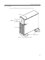
9.2
166
Front side
: : : : : : : : : : : : : : : : : : : : : : : : : : : : : : : : : : :
167
9.2.2
Rear side
: : : : : : : : : : : : : : : : : : : : : : : : : : : : : : : : : : :
169
Preparations for Use
: : : : : : : : : : : : : : : : : : : : : : : : : : : : : : : : :
9.3.1
Installation notes
9.3.2
Installation specifications
: : : : : : : : : : : : : : : : : : : : : : : : : : : : : : :
171
171
: : : : : : : : : : : : : : : : : : : : : : : : : : :
172
: : : : : : : : : : : : : : : : : : : : : : : : : : : : : : :
174
9.4
Disk Drive Configuration
9.5
Hot-swapping Redundant Components
: : : : : : : : : : : : : : : : : : : : : : : :
175
: : : : : : : : : : : : : : : : : : : : : : : : : : : : : :
175
: : : : : : : : : : : : : : : : : : : : : : : : : : : : : : :
176
9.5.1
Power supply units
9.5.2
Hard disk drives
Expansion File Unit Type-2
177
10.1
Overview
178
10.2
Names and Functions of Parts
: : : : : : : : : : : : : : : : : : : : : : : : : : : : : : : : : : : : : :
: : : : : : : : : : : : : : : : : : : : : : : : : : : :
178
10.2.1
Front side
: : : : : : : : : : : : : : : : : : : : : : : : : : : : : : : : : : :
178
10.2.2
Rear side
: : : : : : : : : : : : : : : : : : : : : : : : : : : : : : : : : : :
179
10.3
CHAPTER 11
: : : : : : : : : : : : : : : : : : : : : : : : : : : :
9.2.1
9.3
CHAPTER 10
Names and Functions of Parts
Preparations for Use
: : : : : : : : : : : : : : : : : : : : : : : : : : : : : : : : :
10.3.1
Installation notes
10.3.2
Installation specifications
: : : : : : : : : : : : : : : : : : : : : : : : : : : : : : :
180
180
: : : : : : : : : : : : : : : : : : : : : : : : : : :
182
: : : : : : : : : : : : : : : : : : : : : : : : : : : : : :
182
10.4
Disk Drive Configurations
10.5
Hot-swapping Redundant Components
: : : : : : : : : : : : : : : : : : : : : : : :
183
: : : : : : : : : : : : : : : : : : : : : : : : : : : : : :
183
: : : : : : : : : : : : : : : : : : : : : : : : : : : : : : :
184
10.5.1
Power supply units
10.5.2
Hard disk drives
Internal I/O Units
185
11.1
: : : : : : : : : : : : : : : : : : : : : : : : : : : : : : : : : :
186
: : : : : : : : : : : : : : : : : : : : : : : : : : : : : : : : : : :
186
Hard Disk Drives :
11.1.1
SCSI ID
11.1.2
Handling precautions
: : : : : : : : : : : : : : : : : : : : : : : : : : : : :
186
vii
11.1.3
Formatting hard disk drives
11.1.4
Backing up data
11.1.5
Hot-swapping hard disk drives
11.2
186
: : : : : : : : : : : : : : : : : : : : : : : : : : : : : : :
187
: : : : : : : : : : : : : : : : : : : : : : : :
187
: : : : : : : : : : : : : : : : : : : : : : : : : : : : : : : : : : :
188
11.2.1
Names and functions of parts
11.2.2
CD-ROM discs
11.2.3
CD-ROM disc handling precautions :
11.2.4
11.2.5
11.3
: : : : : : : : : : : : : : : : : : : : : : : : :
188
: : : : : : : : : : : : : : : : : : : : : : : : : : : : : : : :
189
: : : : : : : : : : : : : : : : : : : : :
189
Inserting a CD-ROM disc
: : : : : : : : : : : : : : : : : : : : : : : : : : :
190
Ejecting a CD-ROM disc
: : : : : : : : : : : : : : : : : : : : : : : : : : :
190
: : : : : : : : : : : : : : : : : : : : : : : : : : : : : : : : :
191
DAT Drive (DDS3) :
11.3.1
Names and functions of parts
11.3.2
SCSI ID
11.3.3
OS settings
11.3.4
Data cartridges
11.3.5
Data cartridge handling precautions
11.3.6
Write-protecting a data cartridge
11.3.7
: : : : : : : : : : : : : : : : : : : : : : : : :
191
: : : : : : : : : : : : : : : : : : : : : : : : : : : : : : : : : : :
192
: : : : : : : : : : : : : : : : : : : : : : : : : : : : : : : : : :
: : : : : : : : : : : : : : : : : : : : : : : : : : : : : : : :
193
194
: : : : : : : : : : : : : : : : : : : : : :
195
: : : : : : : : : : : : : : : : : : : : : : :
196
Loading a data cartridge
: : : : : : : : : : : : : : : : : : : : : : : : : : :
196
11.3.8
Ejecting a data cartridge
: : : : : : : : : : : : : : : : : : : : : : : : : : :
196
11.3.9
Cleaning the tape heads
: : : : : : : : : : : : : : : : : : : : : : : : : : : :
197
: : : : : : : : : : : : : : : : : : : : : : : : : : : : : : : : :
198
11.4
viii
CD-ROM Drive
: : : : : : : : : : : : : : : : : : : : : : : : : :
DAT Drive (DDS4) :
11.4.1
Names and functions of parts
11.4.2
SCSI ID
11.4.3
OS settings
11.4.3.1
PRIMEPOWER200 Non-Pedestal Servers
11.4.3.2
PRIMEPOWER200 Pedestal Servers
11.4.4
Data cartridges
11.4.5
Data cartridge handling precautions
11.4.6
Write-protecting a data cartridge
11.4.7
Loading a data cartridge
: : : : : : : : : : : : : : : : : : : : : : : : :
198
: : : : : : : : : : : : : : : : : : : : : : : : : : : : : : : : : : :
199
: : : : : : : : : : : : : : : : : : : : : : : : : : : : : : : : : :
200
: : : : : : : : : : : : : : : : : :
200
: : : : : : : : : : : : : : : : : : : : :
201
: : : : : : : : : : : : : : : : : : : : : : : : : : : : : : : :
203
: : : : : : : : : : : : : : : : : : : : : :
204
: : : : : : : : : : : : : : : : : : : : : : :
205
: : : : : : : : : : : : : : : : : : : : : : : : : : :
205
CONTENTS
11.4.8
Ejecting a data cartridge
11.4.9
Cleaning the tape heads
11.5
CHAPTER 13
205
: : : : : : : : : : : : : : : : : : : : : : : : : : : :
206
: : : : : : : : : : : : : : : : : : : : : : : : : : : : : : : : : : :
207
11.5.1
Names and function of parts
11.5.2
SCSI ID
11.5.3
OS settings
11.5.4
Data cartridges
11.5.5
Data cartridge handling precautions
11.5.6
Write-protecting a data cartridge
11.5.7
: : : : : : : : : : : : : : : : : : : : : : : : :
207
: : : : : : : : : : : : : : : : : : : : : : : : : : : : : : : : : : :
208
: : : : : : : : : : : : : : : : : : : : : : : : : : : : : : : : : :
: : : : : : : : : : : : : : : : : : : : : : : : : : : : : : : :
208
210
: : : : : : : : : : : : : : : : : : : : : :
210
: : : : : : : : : : : : : : : : : : : : : : :
211
Loading a data cartridge
: : : : : : : : : : : : : : : : : : : : : : : : : : :
211
11.5.8
Ejecting a data cartridge
: : : : : : : : : : : : : : : : : : : : : : : : : : :
212
11.5.9
Cleaning the tape heads
: : : : : : : : : : : : : : : : : : : : : : : : : : : :
212
: : : : : : : : : : : : : : : : : : : : : : : : : : : : : : : : : : :
215
11.6
CHAPTER 12
8mm Tape Drive
: : : : : : : : : : : : : : : : : : : : : : : : : : :
DLT Tape Drive
11.6.1
Names and functions of parts
11.6.2
SCSI ID
11.6.3
OS settings
11.6.4
Data cartridge
11.6.5
Data cartridge handling precautions
11.6.6
Write-protecting a data cartridge
11.6.7
: : : : : : : : : : : : : : : : : : : : : : : : :
215
: : : : : : : : : : : : : : : : : : : : : : : : : : : : : : : : : : :
217
: : : : : : : : : : : : : : : : : : : : : : : : : : : : : : : : : :
: : : : : : : : : : : : : : : : : : : : : : : : : : : : : : : :
218
219
: : : : : : : : : : : : : : : : : : : : : :
220
: : : : : : : : : : : : : : : : : : : : : : :
221
Loading a data cartridge
: : : : : : : : : : : : : : : : : : : : : : : : : : :
221
11.6.8
Ejecting a data cartridge
: : : : : : : : : : : : : : : : : : : : : : : : : : :
222
11.6.9
Cleaning the tape heads
: : : : : : : : : : : : : : : : : : : : : : : : : : : :
223
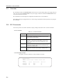
RCI Commands
227
12.1
Overview
228
12.2
RCI Commands
: : : : : : : : : : : : : : : : : : : : : : : : : : : : : : : : : : : : : :
: : : : : : : : : : : : : : : : : : : : : : : : : : : : : : : : : : :
Troubleshooting
228
231
ix
CHAPTER 14
13.1
Overview
13.2
Checking Errors from the ok Prompt
13.3
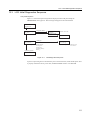
LCD Initial Diagnostics Sequence
13.4
13.5
232
: : : : : : : : : : : : : : : : : : : : : : : : :
232
: : : : : : : : : : : : : : : : : : : : : : : : : :
233
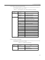
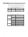
SCF Error Messages
: : : : : : : : : : : : : : : : : : : : : : : : : : : : : : : : :
234
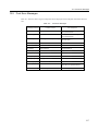
Post Error Messages
: : : : : : : : : : : : : : : : : : : : : : : : : : : : : : : : :
237
Glossary
14.1
x
: : : : : : : : : : : : : : : : : : : : : : : : : : : : : : : : : : : : : :
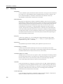
Glossary
239
: : : : : : : : : : : : : : : : : : : : : : : : : : : : : : : : : : : : : : :
240
ILLUSTRATIONS
Figure 2.1
PRIMEPOWER200 Pedestal Server
Figure 2.2
Front of PRIMEPOWER200 Pedestal Server
Figure 2.3
Control Panel
Figure 2.4
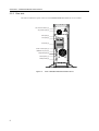
Rear of PRIMEPOWER200 Pedestal Server
Figure 2.5
: : : : : : : : : : : : : : : : : : : : : : : : : : :
4
: : : : : : : : : : : : : : : : : : : : : : :
5
: : : : : : : : : : : : : : : : : : : : : : : : : : : : : : : : : : : : : :
6
: : : : : : : : : : : : : : : : : : : : : : :
8
Turning the power on :
: : : : : : : : : : : : : : : : : : : : : : : : : : : : : : : : : :
15
Figure 2.6
Turning the power off
: : : : : : : : : : : : : : : : : : : : : : : : : : : : : : : : : :
17
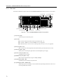
Figure 2.7
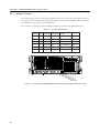
PRIMEPOWER200 Pedestal Server Systemboard
Figure 2.8
PRIMEPOWER200 Disk Drive Configuration
Figure 2.9
Rear of PRIMEPOWER200 Pedestal Server showing position of PCI slots
Figure 3.1
PRIMEPOWER200 Rackmount (4U) Server
Figure 3.2
Front of PRIMEPOWER200 Rackmount (4U) Server
Figure 3.3
Control Panel
Figure 3.4
Rear of PRIMEPOWER200 Rackmount (4U) Server
Figure 3.5
: : : : : : : : : : : : : : : : : : : :
20
: : : : : : : : : : : : : : : : : : : : : :
22
: : : : : : : :
24
: : : : : : : : : : : : : : : : : : : : : : :
26
: : : : : : : : : : : : : : : : : : :
27
: : : : : : : : : : : : : : : : : : : : : : : : : : : : : : : : : : : : : :
27
: : : : : : : : : : : : : : : : : : :
30
Turning the power on :
: : : : : : : : : : : : : : : : : : : : : : : : : : : : : : : : : :
36
Figure 3.6
Turning the power off
: : : : : : : : : : : : : : : : : : : : : : : : : : : : : : : : : :
38
Figure 3.7
PRIMEPOWER200 Rackmount (4U) Systemboard
Figure 3.8
Rear View of PRIMEPOWER200 Rackmount (4U) showing position of PCI slots
Figure 4.1
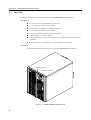
PRIMEPOWER400 Pedestal Server
Figure 4.2
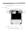
Front of PRIMEPOWER400 Pedestal Server
Figure 4.3
Control Panel
Figure 4.4
Rear of PRIMEPOWER400 Pedestal Server
Figure 4.5
Turning the power on :
: : : : : : : : : : : : : : : : : : : :
41
: : : :
44
: : : : : : : : : : : : : : : : : : : : : : : : : : :
46
: : : : : : : : : : : : : : : : : : : : : : :
47
: : : : : : : : : : : : : : : : : : : : : : : : : : : : : : : : : : : : : :
48
: : : : : : : : : : : : : : : : : : : : : : :
51
: : : : : : : : : : : : : : : : : : : : : : : : : : : : : : : : : :
56
xi
xii
Figure 4.6
Turning the power off
Figure 4.7
PRIMEPOWER400 Pedestal Server Systemboard
Figure 4.8
PRIMEPOWER400 Pedestal Server PCI boards
Figure 4.9
Rear of PRIMEPOWER400 Pedestal Server showing position of PCI slots
Figure 5.1
PRIMEPOWER400 Rackmount (4U) Server
Figure 5.2
Front of PRIMEPOWER400 Rackmount (4U) Server
Figure 5.3
Control Panel
Figure 5.4
Rear of PRIMEPOWER400 Rackmount (4U) Server
Figure 5.5
: : : : : : : : : : : : : : : : : : : : : : : : : : : : : : : : : :
58
: : : : : : : : : : : : : : : : : : : :
61
: : : : : : : : : : : : : : : : : : : : :
62
: : : : : : : :
66
: : : : : : : : : : : : : : : : : : : : : : :
68
: : : : : : : : : : : : : : : : : : :
69
: : : : : : : : : : : : : : : : : : : : : : : : : : : : : : : : : : : : : :
69
: : : : : : : : : : : : : : : : : : :
72
Turning the power on :
: : : : : : : : : : : : : : : : : : : : : : : : : : : : : : : : : :
78
Figure 5.6
Turning the power off
: : : : : : : : : : : : : : : : : : : : : : : : : : : : : : : : : :
79
Figure 5.7
PRIMEPOWER400 Rackmount (4U) Systemboard
Figure 5.8
Rear of PRIMEPOWER400 Rackmount (4U) showing position of PCI slots
Figure 6.1
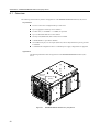
PRIMEPOWER400 Rackmount (10U) Server
Figure 6.2
Front of PRIMEPOWER400 Rackmount (10U) Server
Figure 6.3
Control Panel
Figure 6.4
Rear of PRIMEPOWER400 Rackmount (10U) Server
Figure 6.5
: : : : : : : : : : : : : : : : : : : :
83
: : : : : : :
87
: : : : : : : : : : : : : : : : : : : : : :
90
: : : : : : : : : : : : : : : : : :
91
: : : : : : : : : : : : : : : : : : : : : : : : : : : : : : : : : : : : : :
92
: : : : : : : : : : : : : : : : : :
94
Turning the power on :
: : : : : : : : : : : : : : : : : : : : : : : : : : : : : : : : : :
102
Figure 6.6
Turning the power off
: : : : : : : : : : : : : : : : : : : : : : : : : : : : : : : : : :
104
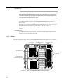
Figure 6.7
PRIMEPOWER400 Rackmount (10U) Systemboard
Figure 6.8
PRIMEPOWER400 Rackmount (10U) PCI boards
Figure 6.9
Rear of PRIMEPOWER400 Rackmount (10U) showing position of PCI slots
Figure 7.1
PRIMEPOWER600 Pedestal Server
Figure 7.2
Front of PRIMEPOWER600 Pedestal Server
Figure 7.3
Control Panel
Figure 7.4
Rear of PRIMEPOWER600 Pedestal Server
Figure 7.5
: : : : : : : : : : : : : : : : : : :
108
: : : : : : : : : : : : : : : : : : : :
109
: : : : : : :
113
: : : : : : : : : : : : : : : : : : : : : : : : : : :
116
: : : : : : : : : : : : : : : : : : : : : : :
117
: : : : : : : : : : : : : : : : : : : : : : : : : : : : : : : : : : : : : :
118
: : : : : : : : : : : : : : : : : : : : : : :
121
Turning the power on :
: : : : : : : : : : : : : : : : : : : : : : : : : : : : : : : : : :
127
Figure 7.6
Turning the power off
: : : : : : : : : : : : : : : : : : : : : : : : : : : : : : : : : :
129
Figure 7.7
PRIMEPOWER600 Pedestal Server Systemboard
Figure 7.8
PRIMEPOWER600 Pedestal Server Expansion Systemboard (Option)
Figure 7.9
Rear of PRIMEPOWER600 Pedestal Server showing position of PCI slots
Figure 8.1
PRIMEPOWER600 Rackmount (10U) Server
Figure 8.2
Front of PRIMEPOWER600 Rackmount (10U) Server
Figure 8.3
Control panel :
Figure 8.4
Rear of PRIMEPOWER600 Rackmount (10U) Server
Figure 8.5
Figure 8.6
: : : : : : : : : : : : : : : : : : : :
: : : : : : : : : :
133
134
: : : : : : : :
138
: : : : : : : : : : : : : : : : : : : : : :
140
: : : : : : : : : : : : : : : : : :
141
: : : : : : : : : : : : : : : : : : : : : : : : : : : : : : : : : : : : : :
142
: : : : : : : : : : : : : : : : : :
144
Turning the power on :
: : : : : : : : : : : : : : : : : : : : : : : : : : : : : : : : : :
150
Turning the power off
: : : : : : : : : : : : : : : : : : : : : : : : : : : : : : : : : :
152
ILLUSTRATIONS
Figure 8.7
PRIMEPOWER600 Rackmount (10U) Base Systemboard
Figure 8.8
PRIMEPOWER600 Rackmount (10U) Expansion Systemboard (Option)
Figure 8.9
Rear View of PRIMEPOWER600 Rackmount (10U) showing position of PCI slots
Figure 9.1
: : : : : : : : : : : : : : : :
: : : : : : : : :
156
157
: : : :
163
Front of Expansion Disk Cabinet
: : : : : : : : : : : : : : : : : : : : : : : : : : : : :
167
Figure 9.2
Rear of Expansion Disk Cabinet
: : : : : : : : : : : : : : : : : : : : : : : : : : : : :
169
Figure 9.3
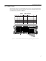
Full Disk Drive Configuration of Expansion Disk Cabinet
Figure 10.1
: : : : : : : : : : : : : : : :
174
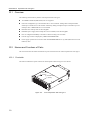
Front of Expansion File Unit Type-2
: : : : : : : : : : : : : : : : : : : : : : : : : : :
178
Figure 10.2
Rear of Expansion File Unit Type-2
: : : : : : : : : : : : : : : : : : : : : : : : : : :
179
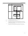
Figure 10.3
Full Disk Drive Configuration of Expansion File Unit Type-2
Figure 10.4
Disk Drive + Tape Drive Configuration of Expansion File Unit Type-2
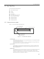
Figure 11.1
Front Panel CD-ROM Drive
Figure 11.2
CD-ROM Disc Mark
Figure 11.3
Front Panel of DDS3 DAT Drive
Figure 11.4
DAT Data Cartridge Write-protection Tab
Figure 11.5
Front Panel of DDS4 DAT Drive
Figure 11.6
DAT Data Cartridge Write-protection Tab
Figure 11.7
Front Panel of 8mm Tape Drive
Figure 11.8
8mm Tape Drive Data Cartridge Write-protection Tab
Figure 11.9
Appearance of Cleaning Cartridge
Figure 11.10
Front Panel of DLT Tape Drive
Figure 11.11
Data Cartridge Write-protection Tab
Figure 13.1
Initial Diagnostics Sequence
: : : : : : : : : : : : : : :
183
: : : : : : : : : :
183
: : : : : : : : : : : : : : : : : : : : : : : : : : : : : : :
188
: : : : : : : : : : : : : : : : : : : : : : : : : : : : : : : : : : :
189
: : : : : : : : : : : : : : : : : : : : : : : : : : : : :
191
: : : : : : : : : : : : : : : : : : : : : : : :
196
: : : : : : : : : : : : : : : : : : : : : : : : : : : : :
198
: : : : : : : : : : : : : : : : : : : : : : : :
205
: : : : : : : : : : : : : : : : : : : : : : : : : : : : :
207
: : : : : : : : : : : : : : : : : :
211
: : : : : : : : : : : : : : : : : : : : : : : : : : : :
214
: : : : : : : : : : : : : : : : : : : : : : : : : : : : : :
215
: : : : : : : : : : : : : : : : : : : : : : : : : : :
221
: : : : : : : : : : : : : : : : : : : : : : : : : : : : : : :
233
xiii
TABLES
xiv
Table 1.1
Data protection method :
: : : : : : : : : : : : : : : : : : : : : : : : : : : : : : : : :
2
Table 2.1
MODE Switch Settings :
: : : : : : : : : : : : : : : : : : : : : : : : : : : : : : : : :
6
Table 2.2
Installation Specifications of the PRIMEPOWER200 Pedestal Server (1/2)
: : : : : : : :
12
Table 2.3
Installation Specifications of the PRIMEPOWER200 Pedestal Server (2/2)
: : : : : : : :
13
Table 2.4
Allowed CPU Module Configurations
: : : : : : : : : : : : : : : : : : : : : : : : : :
21
Table 2.5
PCI Slot Specifications
: : : : : : : : : : : : : : : : : : : : : : : : : : : : : : : : : :
24
Table 3.1
MODE Switch Settings :
Table 3.2
Installation Specifications of the PRIMEPOWER200 Rackmount (4U) Server (1/2)
: : : :
33
Table 3.3
Installation Specifications of the PRIMEPOWER200 Rackmount (4U) Server (2/2)
: : : :
34
Table 3.4
Allowed CPU Module Configurations
: : : : : : : : : : : : : : : : : : : : : : : : : :
42
Table 3.5
PCI Slot Specifications
: : : : : : : : : : : : : : : : : : : : : : : : : : : : : : : : : :
44
Table 4.1
MODE Switch Settings :
Table 4.2
Installation Specifications of the PRIMEPOWER400 Pedestal Server (1/2)
: : : : : : : :
53
Table 4.3
Installation Specifications of the PRIMEPOWER400 Pedestal Server (2/2)
: : : : : : : :
54
Table 4.4
Allowed CPU Module Configurations
: : : : : : : : : : : : : : : : : : : : : : : : : :
63
Table 4.5
PCI Slot Specifications
: : : : : : : : : : : : : : : : : : : : : : : : : : : : : : : : : :
65
Table 5.1
MODE Switch Settings :
Table 5.2
Installation Specifications of the PRIMEPOWER400 Rackmount (4U) Server (1/2)
: : : :
75
Table 5.3
Installation Specifications of the PRIMEPOWER400 Rackmount (4U) Server (2/2)
: : : :
76
Table 5.4
Allowed CPU Module Configurations
: : : : : : : : : : : : : : : : : : : : : : : : : :
85
Table 5.5
PCI Slot Specifications
: : : : : : : : : : : : : : : : : : : : : : : : : : : : : : : : : :
87
: : : : : : : : : : : : : : : : : : : : : : : : : : : : : : : : :
: : : : : : : : : : : : : : : : : : : : : : : : : : : : : : : : :
: : : : : : : : : : : : : : : : : : : : : : : : : : : : : : : : :
28
49
70
TABLES
Table 6.1
MODE Switch Settings :
Table 6.2
Installation Specifications of the PRIMEPOWER400 Rackmount (10U) Server (1/2)
: : :
99
Table 6.3
Installation Specifications of the PRIMEPOWER400 Rackmount (10U) Server (2/2)
: : :
100
Table 6.4
Allowed CPU Module Configurations
: : : : : : : : : : : : : : : : : : : : : : : : : :
111
Table 6.5
PCI Slot Specifications
: : : : : : : : : : : : : : : : : : : : : : : : : : : : : : : : : :
113
Table 7.1
MODE Switch Settings :
Table 7.2
Installation Specifications of the PRIMEPOWER600 Pedestal Server (1/2)
: : : : : : : :
124
Table 7.3
Installation Specifications of the PRIMEPOWER600 Pedestal Server (2/2)
: : : : : : : :
125
Table 7.4
Allowed CPU Module Configurations
: : : : : : : : : : : : : : : : : : : : : : : : : :
135
Table 7.5
PCI Slot Specifications
: : : : : : : : : : : : : : : : : : : : : : : : : : : : : : : : : :
137
Table 8.1
MODE Switch Settings :
Table 8.2
Installation Specifications of the PRIMEPOWER600 Rackmount (10U) Server (1/2)
: : :
148
Table 8.3
Installation Specifications of the PRIMEPOWER600 Rackmount (10U) Server (2/2)
: : :
149
Table 8.4
Allowed CPU Module Configurations
: : : : : : : : : : : : : : : : : : : : : : : : : :
159
Table 8.5
PCI Slot Specifications
: : : : : : : : : : : : : : : : : : : : : : : : : : : : : : : : : :
162
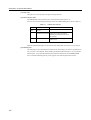
Table 9.1
CHECK LED Indicator
: : : : : : : : : : : : : : : : : : : : : : : : : : : : : : : : : :
168
Table 9.2
Installation Specifications of the Expansion Disk Cabinet (1/2)
: : : : : : : : : : : : : :
172
Table 9.3
Installation Specifications of the Expansion Disk Cabinet (2/2)
: : : : : : : : : : : : : :
173
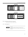
Table 10.1
CHECK LED
: : : : : : : : : : : : : : : : : : : : : : : : : : : : : : : : : : : : : :
179
Table 10.2
Installation Specification of Expansion File Unit Type-2
Table 11.1
DDS3 DAT Drive LED Indicators
Table 11.2
DDS3 DAT Data cartridges
Table 11.3
DAT Cleaning Cartridge
Table 11.4
DAT Drive LED Indicators
: : : : : : : : : : : : : : : : : : : : : : : : : : : : : : : :
199
Table 11.5
DDS4 DAT Data cartridges
: : : : : : : : : : : : : : : : : : : : : : : : : : : : : : : :
203
Table 11.6
DAT Cleaning Cartridge
: : : : : : : : : : : : : : : : : : : : : : : : : : : : : : : : :
206
Table 11.7
8mm Tape Unit LED States
Table 11.8
Supported Data Formats (8mm Tape Drive) :
Table 11.9
Density Codes When Specifying Data Formats
Table 11.10
8mm Data Cartridges
Table 11.11
8mm Cleaning Cartridge
Table 11.12
DLT Data Cartridges
Table 11.13
DLT Cleaning Cartridge
Table 12.1
List Of Commands
Table 13.1
show-post-results Command
: : : : : : : : : : : : : : : : : : : : : : : : : : : : : : : : :
: : : : : : : : : : : : : : : : : : : : : : : : : : : : : : : : :
: : : : : : : : : : : : : : : : : : : : : : : : : : : : : : : : :
93
119
143
: : : : : : : : : : : : : : : : :
182
: : : : : : : : : : : : : : : : : : : : : : : : : : : :
192
: : : : : : : : : : : : : : : : : : : : : : : : : : : : : : : :
194
: : : : : : : : : : : : : : : : : : : : : : : : : : : : : : : : :
197
: : : : : : : : : : : : : : : : : : : : : : : : : : : : : : :
: : : : : : : : : : : : : : : : : : : : : : :
208
209
: : : : : : : : : : : : : : : : : : : : : :
209
: : : : : : : : : : : : : : : : : : : : : : : : : : : : : : : : : : :
210
: : : : : : : : : : : : : : : : : : : : : : : : : : : : : : : : :
213
: : : : : : : : : : : : : : : : : : : : : : : : : : : : : : : : : : :
219
: : : : : : : : : : : : : : : : : : : : : : : : : : : : : : : : :
225
: : : : : : : : : : : : : : : : : : : : : : : : : : : : : : : : : : : :
228
: : : : : : : : : : : : : : : : : : : : : : : : : : : : : : :
232
xv
xvi
Table 13.2
Power Supply Unit Configuration Error Messages
Table 13.3
Power Supply Unit, Fans, and Environmental Error Messages
Table 13.4
CPU Monitor Error Massages
Table 13.5
Lithium Battery Error Messages
Table 13.6
Other Error Massages
Table 13.7
Post Error Messages
: : : : : : : : : : : : : : : : : : : :
234
: : : : : : : : : : : : : :
235
: : : : : : : : : : : : : : : : : : : : : : : : : : : : : :
235
: : : : : : : : : : : : : : : : : : : : : : : : : : : : :
236
: : : : : : : : : : : : : : : : : : : : : : : : : : : : : : : : : :
236
: : : : : : : : : : : : : : : : : : : : : : : : : : : : : : : : : : :
237
1
Features of the PRIMEPOWER Servers
The features of the PRIMEPOWER servers are as follows:
High-performance SPARC64 GP Processors
The SPARC64 GP is a high-performance processor with an out-of-order execution engine.
The SPARC64 GP features high-speed arithmetic operations with high-precision Branch
Prediction
The SPARC64 GP supports a large external cache and on-chip cache.
ECC (error correcting code) is used in both the on-chip and external caches.
High-performance Multi-Processor Platform
Symmetric Multiprocessing (SMP) architecture (maximum number of CPUs varies from model
to model).
Memory interleaving (maximum number of interleaves varies from model to model).
Implements a packet-based bus protocol, with a throughput of 1.3 to 1.6 GB/s per processor.
A high-speed crossbar switched multiprocessor interface is used. This enables simultaneous
operation of multiple processors, I/O and memory devices and faster data transfers.
High-speed I/O interface
The following high-speed I/O interfaces are provided as standard:
100Base-TX (100/10 Mbps auto-sensing)
64-bit PCI (Peripheral Component Interconnect) busses
1
CHAPTER 1 Features of the PRIMEPOWER Servers
High-performance, Large-capacity Storage Devices
Ultra SCSI disk drives (10,000rpm) can be added (maximum number of drives varies from
model to model).
A CD-ROM drive is provided as standard.
One DAT unit, 8mm tape drive or DLT tape drive can be added as an option (various tape
drives are available, compatibility will vary from model to model).
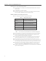
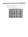
Reliability, Availability and Serviceability (RAS) Features
ECC or parity protects the data for components and interfaces.
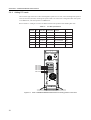
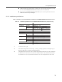
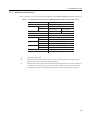
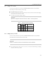
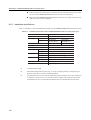
Table 1.1
Data protection method
Components and interfaces
Data protection method
Processor
(on-chip & external cache)
ECC (correct 1 bit and detect 2 bits)
Memory
ECC (correct 1 bit and detect 2 bits)
Data path
ECC (correct 1 bit and detect 2 bits)
Address path
Parity
I/O bus (PCI)
Parity
Processor operation
Monitoring by SCF service processor
Built-in basic SCSI, LAN
Parity, IP checksum
Note:
ECC or parity does not protect the RS-232C serial interface and floppy disk.
Power-on diagnostics are conducted on system components such as processors and memory.
Automatic System Reconfiguration (ASR) isolates faulty hardware components such as
processors and memory modules immediately after detection.
A SCF (System Control Facility), which has an integrated service processor, monitors the
operation of the SPARC64 GP processors, environmental temperatures, power and fans.
Status of LEDs and messages on the LCD panel indicate the status when an error occurs.
The RCI (Remote Cabinet Interface) allows control over power cycling of expansion I/O units,
such as the Expansion Disk Cabinet and Expansion File Unit Type-2, and monitors for errors.
Internal disk drives are hot-swappable. In addition, redundant power supplies and fans are
supported for high availability. (PRIMEPOWER200 Pedestal Server does not support it.)
Lockable cover panels to prevent unauthorized access to the internal I/O devices. (Rackmount
type server does not support it.)
2
2
PRIMEPOWER200 Pedestal Server
This chapter gives an overview of the PRIMEPOWER200 Pedestal Server, names and functions of parts,
preparations for use, and how to expand the server unit.
CONTENTS
2.1
2.2
2.3
2.4
Overview . . . . . . . . . . . . . . . . . . . . . . . . . . . . . . . . . . . . . . . . . . . . . . . . . . . . . . . . . . . . . . . . . . . . . . . . . . . . . . . . . . . . . . . 4
Names and Functions of Parts . . . . . . . . . . . . . . . . . . . . . . . . . . . . . . . . . . . . . . . . . . . . . . . . . . . . . . . . . . . . . . . . . . . . . 5
Preparations for Use . . . . . . . . . . . . . . . . . . . . . . . . . . . . . . . . . . . . . . . . . . . . . . . . . . . . . . . . . . . . . . . . . . . . . . . . . . .
10
Expanding the Server Unit . . . . . . . . . . . . . . . . . . . . . . . . . . . . . . . . . . . . . . . . . . . . . . . . . . . . . . . . . . . . . . . . . . . . .
20
3
CHAPTER 2 PRIMEPOWER200 Pedestal Server
2.1 Overview
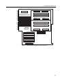
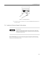
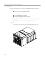
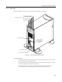
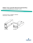
The following describes the key features and appearance of the PRIMEPOWER200 Pedestal Server.
Key Features
The server unit can be configured with up to two CPUs.
Up to 16 gigabytes of memory can be mounted.
Six PCI slots (2 x 33/66MHz + 4 x 33MHz) are provided.
Up to eight UltraSCSI disk drives can be built in.
One tape unit (DDS4 DAT, 8mm) can be installed.
A CD-ROM drive is provided as standard.
One 100Base-TX port, two serial ports (RS-232C) and one keyboard/mouse port are provided
as standard.
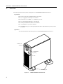
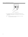
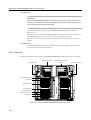
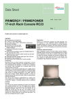
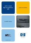
Appearance
The following illustration shows the appearance of the PRIMEPOWER200 Pedestal Server.
CHECK LED
(Amber)
POWER LED
(Green)
Lock
Stabilizing Feet
Figure 2.1
4
PRIMEPOWER200 Pedestal Server
2.2 Names and Functions of Parts
2.2 Names and Functions of Parts
This section describes the names and functions of parts on the front, control panel and rear of the
PRIMEPOWER200 Pedestal Server.
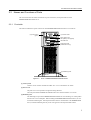
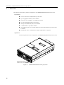
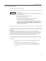
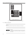
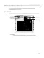
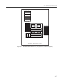
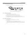
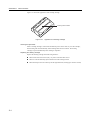
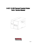
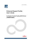
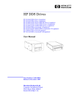
2.2.1 Front side
The names and functions of parts on the front of the PRIMEPOWER200 Pedestal Server are as follows.
(2) Panel Cover
(open)
(1) Control Panel
8mm Tape Unit or
DAT (DDS4) Unit (option)
CD-ROM Unit
Floppy Disk Unit
(maintenance only)
(3) Stabilizing Feet
Figure 2.2
Front of PRIMEPOWER200 Pedestal Server
(1) Control panel
Contains various switches and indicator LEDs. See "2.2.2 Control Panel" for details.
(2) Panel cover
The panel cover can be opened to its right after being unlocked.
The LCD panel and the POWER and CHECK LEDs can be checked with the cover closed.
(3) Stabilizing feet
The stabilizing feet prevent the PRIMEPOWER200 Pedestal Server from falling over when pushed
from the side or in an earthquake. When installing the PRIMEPOWER200 Pedestal Server, be sure
to attach the stabilizing feet. If the Expansion Disk Cabinet is installed next to the PRIMEPOWER
Server, install the stabilizing feet only on the side opposite to the Expansion Disk Cabinet.
5
CHAPTER 2 PRIMEPOWER200 Pedestal Server
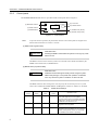
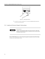
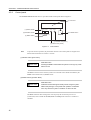
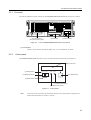
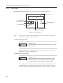
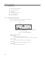
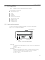
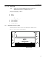
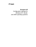
2.2.2
Control panel
The PRIMEPOWER200 Pedestal Server is provided with the control panel shown in Figure 2.3 .
REQUEST
(3) REQUEST Switch
POWER
(4) LCD Panel
(5) POWER Switch
RESET
(1) RESET Switch
CHECK
(2) MODE Switch
POWER
(7) POWER LED (Green)
AUTO
MANUAL
SECURE
(6) CHECK LED (Amber)
Figure 2.3
Note:
Control Panel
To prevent erroneous operation, all push-button switches on the control panel are designed not to
function unless held down for at least 0.3 seconds.
(1) RESET switch (push button)
Data Destruction
CAUTION
Pressing the RESET switch while the system is running may cause
data to be lost.
The RESET switch is used to reset the system to its initial state and is enabled or disabled by the
MODE switch described in "(2) MODE Switch".
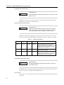
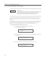
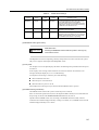
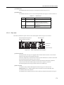
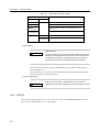
(2) MODE switch (3-position slider)
Data Destruction
CAUTION
Install the "Enhanced Support Facility" before using the system.
Without this package, a front panel-miss operation or hardware
error may cause the system to shutdown or data to be lost.
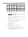
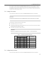
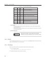
The MODE switch has three settings and is used to specify the run mode at power on or system
reboot, and to whether the POWER, RESET and REQUEST switches are "enabled" or "disabled".
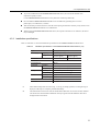
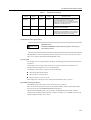
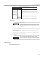
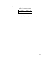
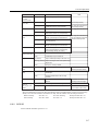
Table 2.1
MODE
switch
6
POWER
switch
RESET
switch
MODE Switch Settings
REQUEST
switch
Operation mode
MANUAL
Enabled
Enabled
Enabled
The bootup sequence stops at an ok prompt
after initial diagnostics are completed.
Use this mode to enter commands and make
settings from the ok prompt when performing
maintenance on the server unit.
AUTO
Enabled
Disabled
Disabled
The OS is automatically booted after initial
diagnostics are completed.
SECURE
Disabled
Disabled
Disabled
The OS is automatically booted after initial
diagnostics are completed. The TTY terminal
"break" and keyboard "STOP+A" commands
are disabled while Solaris is operating.
2.2 Names and Functions of Parts
(3) REQUEST switch (push button)
Data Destruction
CAUTION
Pressing the REQUEST switch while the system is running may
cause data to be lost.
The REQUEST switch is for outputting a memory dump when an error has occurred in the system.
Only service engineers should operate the REQUEST switch.
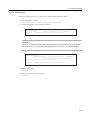
(4) LCD panel
The 16-digit x 2-row LCD panel displays the status of initial diagnostics performed when the power
is turned on.
It also displays error messages when a hardware error has been detected. For details on error
messages that may be displayed, see "13 Troubleshooting".
A LCD panel error message is cleared by one of the following:
When the problem has been fixed
When the power is next turned on
When the AC main line switch is turned off
Some displayed error messages may be cleared when the RESET switch is pressed.
(5) POWER switch (push button)
The POWER switch instructs the system to turn the power on and off.
Power on and off of expansion units (such as the Expansion Disk Cabinet) is interlocked with the
powering on and off of the PRIMEPOWER200 Pedestal Server.
Operation of the POWER switch varies according to the MODE switch and scftool (software
contained in the "Enhanced Support Facility") settings. For details, see "(2) MODE switch" and the
"Enhanced Support Facility User’s Guide."
(6) CHECK LED
IMPORTANT
When the PRIMEPOWER200 Pedestal Server detects an error in the power line or
abnormal temperatures, the CHECK LED blinks and the power is automatically turned off
to prevent unit damage and ensure safety.
The CHECK LED blinks or lights up when the PRIMEPOWER200 Pedestal Server detects an error.
When the power is turned on, the CHECK LED lights up and then goes out. This is not an error. If
the CHECK LED stays lit and does not go out at power on, this indicates an error.
When an error occurs, note down the details displayed on the LCD panel, and contact a service
engineer.
(7) POWER LED
The POWER LED indicates the power state of the system. This LED lights up when the power is
on, and goes out when the power is turned off.
7
CHAPTER 2 PRIMEPOWER200 Pedestal Server
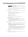
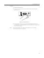
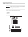
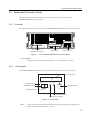
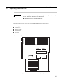
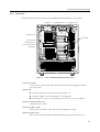
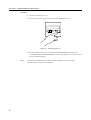
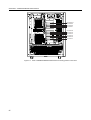
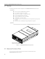
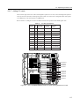
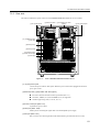
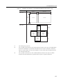
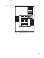
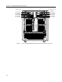
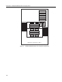
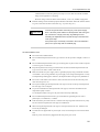
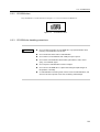
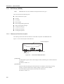
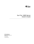
2.2.3 Rear side
The names and functions of parts on the rear of the PRIMEPOWER200 Pedestal Server are as follows.
AC main line switch (1)
AC power input (2)
UPS port (5)
RCI port (6)
PCI slots (3)
Power control port (4)
100Base-TX port (10)
Keyboard port (9)
Serial port A (7)
Serial port B (8)
Figure 2.4
8
Rear of PRIMEPOWER200 Pedestal Server
2.2 Names and Functions of Parts
(1) AC main line switch
The PRIMEPOWER200 Pedestal Server is turned on by the POWER switch on the front of the
server unit when this switch is set to the "|" position.
(2) AC power input
Connect the power cable to this point.
(3) PCI slots
PCI slots conform to the PCI local bus specification (Rev. 2.1).
64-bit bus, 33MHz (5.0 V) and 33/66MHz (3.3V) are supported.
Both short cards (17.46 cm, 6.87 in.) and long cards (31.19 cm, 12.3 in.) are supported.
(4) Power control port (label : PC)
8-pin DIN for power control
(5) UPS port (label : UPS)
Dsub-9 pin for connecting the signal cable of an uninterruptible power supply
(6) RCI port (label : RCI)
RJ11 connector for connecting the RCI cable and terminator (provided with server unit)
(7), (8) Serial ports (label : SERIAL A/B)
Dsub-25 pin ports for connecting a console terminal when performing maintenance on the server
unit using the RS-232C interface
(9) Keyboard port (label : KB)
8-pin DIN port for connecting the keyboard cable
(10) 100Base-TX port (label : LAN)
RJ45 connector automatically recognizes 10Mbps/100Mbps
9
CHAPTER 2 PRIMEPOWER200 Pedestal Server
2.3 Preparations for Use
This section describes the following:
Installation notes and specifications
Connecting the console
Turning power on and off
Installing the Enhanced Support Facility package
Enabling/disabling the break signal
LAN expansion note
2.3.1 Installation notes
CAUTION
Unit Damage
If the following notes are not observed the PRIMEPOWER200 Pedestal Server
may be damaged. Be sure to follow these notes.
Do not block the ventilation holes.
Do not install the PRIMEPOWER200 Pedestal Server where it will be exposed to sunlight or sources of heat.
Do not install the PRIMEPOWER200 Pedestal Server in dusty places or places where it will be exposed to
corrosive gases or sea breezes.
Keep the PRIMEPOWER200 Pedestal Server isolated from vibration. Install the PRIMEPOWER200 Pedestal
Server on a level surface so that it does not tilt.
Make sure that the AC power supply source is grounded properly using a maximum resistance of 100 Ohms.
Also, do not ground the AC power supply source using a shared ground. Use only an independent grounding
point. Otherwise, the PRIMEPOWER200 Pedestal Server may malfunction.
Do not run a cable under a unit or allow a cable to become taut. Do not disconnect the power cable when the
power is on.
Do not place anything on the PRIMEPOWER200 Pedestal Server. Do not use the top of the
PRIMEPOWER200 Pedestal Server as a workspace.
To prevent condensation in the PRIMEPOWER200 Pedestal Server, do not raise the ambient room
temperature rapidly in winter.
Use the PRIMEPOWER200 Pedestal Server only after it has warmed up sufficiently.
Do not install the PRIMEPOWER200 Pedestal Server near EM noise generating devices such as
photocopiers, air conditioners, or welders.
Take electrostatic prevention measures. Note that some carpets generate static electricity easily and can cause
the PRIMEPOWER200 Pedestal Server to malfunction.
When moving the PRIMEPOWER200 Pedestal Server, do not pull on the front cover. Otherwise, the Server
may be damaged.
10
2.3 Preparations for Use
CAUTION
Connect the ground before connecting any of the power supply lines. If all of the
power cables are connected to a single power strip, high leakage current
exceeding the stipulated value may leak through to the earth lead of the power
strip.
If the power strip is not directly connected to the main distribution panel, use a
power strip with an industrial plug.
11
CHAPTER 2 PRIMEPOWER200 Pedestal Server
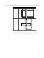
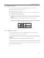
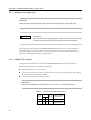
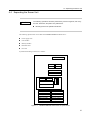
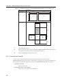
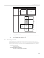
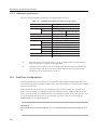
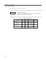
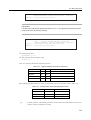
2.3.2 Installation specifications
The following table shows the installation specifications for the PRIMEPOWER200 Pedestal Server.
Table 2.2 Installation Specifications of the PRIMEPOWER200 Pedestal Server (1/2)
Item
Specification
Weight
Power Supply
48 kg (105.96 lb.) (max.)
Frequency
50/60 Hz (+2 ~ -4%)
Voltage
Single phase
Single phase
AC100 ~ 120V (±10%) AC200 ~ 240V (±10%)
Max. Current
Leak Current
² 3.5 mA
Frame Resistance
² 100Ω
2.5 A (240V)
Operating
5 ~ 35 ûC (+41 ~ +95 F) (*1)
Non-operating
0 ~ 50 ûC (+32 ~ +122 F)
Humidity
Operating
20 ~ 80% RH (non-condensing)
Non-operating
8 ~ 80% RH (non-condensing)
Vibration
Operating
0.2 G
Non-operating
0.4 G
Temperature
12
5.0 A (100V)
Noise
47 db(A) (*2)
Form Factor
Pedestal
*1:
If the ambient temperature exceeds 35 deg. C (95 deg. F) during operation, a warning message is
displayed. Take steps to rectify the problem immediately.
*2:
The indicated noise is the mean value of measurements obtained in a low-noise anechoic chamber.
The actual noise measured at the installation site may be greater than the indicated value due to
background noise and echoes.
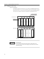
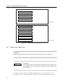
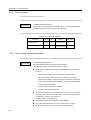
2.3 Preparations for Use
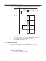
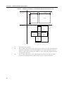
Table 2.3
Installation Specifications of the PRIMEPOWER200 Pedestal Server (2/2)
Item
Specification
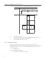
Unit Dimensions
(units : mm)
700 (H)
(28 in.)
Service Areas
(units : mm)
230 (W)
(9 in.)
644 (D)
(25 in.)
Unit Front
Unit Side
478 (*1)
(19 in.)
657 (*1)
(26 in.)
230
Rear ( 9 in. )
Service
Area
800 (*3)
(32 in.)
Side
Service
Area
Front
Service
Area
Unit
Top
800 (*2)
(32 in.)
800 (*3)
(32 in.)
Side
Service
Area
657
(26 in.)
800
(32 in.)
*1:
Including the Stabilizing Feet the width is 478 mm (19-inch) and the depth is 657mm (26-inch).
*2:
If it is possible to move the Server Unit so that 800 mm (32-inch) or more space is available behind
the unit when maintenance is performed, then 200mm (8-inch) of space is adequate is normal use.
However, if optical cables are used, at least 300mm (12-inch) of space will be needed between the
rear of the Unit and the wall.
*3:
If it is possible to move the Server Unit so that 800mm (32-inch) or more space is available beside
the Unit when maintenance is performed, then no space is required in normal use.
13
CHAPTER 2 PRIMEPOWER200 Pedestal Server
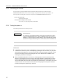
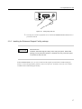
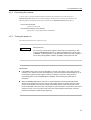
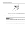
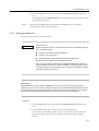
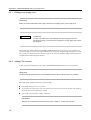
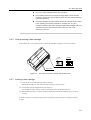
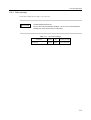
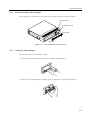
2.3.3 Connecting the console
A device such as a personal computer must be connected to the serial port to act as the console for a
PRIMEPOWER200 Pedestal Server to which a display or keyboard is not connected. Pay attention to the
following when connecting the console to the serial port on the PRIMEPOWER200 Pedestal Server.
Connect the serial cable:
Connect to serial A port.
Communication settings on the terminal:
Set to 8 bits, 1 stop bit, parity OFF, and 9600 baud.
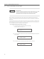
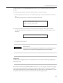
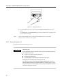
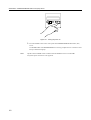
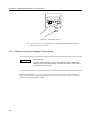
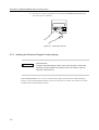
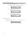
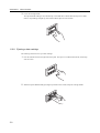
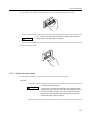
2.3.4 Turning the power on
The following describes how to turn the power on.
CAUTION
Data Destruction
Do not turn the console terminal (device connected to the serial port) on after
turning the PRIMEPOWER Server. When the MODE switch is set to AUTO or
MANUAL, the bootup sequence shifts to display of the ok prompt during Solaris
operation according to the break signal. For this reason, data is sometimes lost.
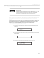
IMPORTANT
If the MODE switch is set to AUTO or SECURE on a server unit on which "auto power control by
software" is set, and the AC power is interrupted (by operating the main line switch, etc.) the power
will sometimes automatically turn on at the moment that the AC power supply is resumed. To keep
the power from being turned on automatically like this, set the MODE switch to MANUAL when
restoring AC power after an interruption.
When the PRIMEPOWER Server is turned on, a self-diagnostics routine automatically verifies
whether or not hardware errors are occurring. If this routine detects any hardware errors, system
power is automatically turned off and on again (if the MODE switch on the control panel is set to
AUTO or SECURE). This power off/on retry sequence is performed twice. In both retries, the routine
checks for errors. If an error occurs in both cases, the routine judges that the system cannot be
booted up and stops the system bootup sequence.
14
2.3 Preparations for Use
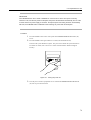
Procedure
1
2
Turn the AC main line power on.
Turn the power switches of the server unit (AC main line switch), console terminal and
peripheral devices on.
Figure 2.5 Turning the power on
3
Press the POWER switch on the control panel of the PRIMEPOWER200 Pedestal Server.
The POWER LEDs of the PRIMEPOWER Server and any peripheral devices connected via the
RCI port should now light up.
Note:
Operation of the POWER switch is disabled when the MODE switch is set to SECURE.
A keyboard power-on function is not supported.
15
CHAPTER 2 PRIMEPOWER200 Pedestal Server
2.3.5 Turning the power off
The following describes how to turn the power off.
CAUTION
Data Destruction
Before turning the power off, check the answer to each of the following points is
"No", or data may be lost:
Are there any currently executing programs?
Are there any current users?
Are floppy disks or tape cartridges still inserted in their drives?
Backup files as necessary before turning the power off.
Also, do not turn off the console while the PRIMEPOWER Server is turned on.
When the MODE switch is set to AUTO or MANUAL, a break signal may cause
the bootup sequence to shift to display of the ok prompt during Solaris operation
potentially causing data to be lost.
IMPORTANT
If the MODE switch is set to AUTO or SECURE on a server unit on which "auto power control by
software" is set, and the AC power is interrupted (by operating the main line switch, etc.) the power
will sometimes automatically turn on at the moment that the AC power supply is resumed. To keep
the power from being turned on automatically like this, set the MODE switch to MANUAL when
restoring AC power after an interruption.
Procedure
1
2
Press the POWER switch on the control panel of the PRIMEPOWER200 Pedestal Server.
Press the POWER switch again within five seconds (scftool default interval).
This starts the system shutdown sequence. The power turns off after the system shuts down.
For details on scftool, refer to the "User’s Guide" included with the "Enhanced Support
Facility."
16
2.3 Preparations for Use
Figure 2.6 Turning the power off
3
Turn the power switches of peripheral devices off after the PRIMEPOWER200 Pedestal Server
power has turned off.
2.3.6 Installing the Enhanced Support Facility package
CAUTION
Data Destruction
Install the "Enhanced Support Facility" before using the system. Without this
package, a front panel-miss operation or hardware error may cause the system
to shutdown or data to be lost.
With the PRIMEPOWER servers, be sure to install all of the programs provided with the "Enhanced Support
Facility" to ensure the high reliability functions of the service processor. For details, refer to the "User’s Guide"
included with the "Enhanced Support Facility."
17
CHAPTER 2 PRIMEPOWER200 Pedestal Server
2.3.7 How to enable/disable the break signal
CAUTION
Data Destruction
If improper commands are used at the ok prompt, data may be lost. If you need
to use any command except those shown in this manual, you should fully
understand the function and usage of the command before using it.
Data is sometimes lost as the bootup sequence shifts to display of the ok prompt during system operation in
response to a break signal from the console terminal connected to the serial port or the STOP+A command from
the keyboard.
To prevent this kind of response to a break signal arriving from the serial port or the STOP+A command from the
keyboard, make the following settings using the set-fw-options command shown below from the ok prompt, and
then set the MODE switch on the control panel to the SECURE mode.
How to disable the break signal and STOP+A command
1
Use the print-fw-options command to check the current setting.
The factory default is that nothing is set.
ok print-fw-options
fw-options =
2
Use the set-fw-options command to set the value (no-break) for disabling the break signal and
STOP command.
ok set-fw-options no-break
fw-options = no-break
3
Use the print-fw-options command to make sure that no-break is correctly set.
ok print-fw-options
fw-options = no-break
18
2.3 Preparations for Use
How to enable the break signal and STOP+A command
1
Use the print-fw-options command to check the current setting values. If the no-break shown
below is not displayed, the break signal and STOP+A command are already enabled.
ok print-fw-options
fw-options = no-break
2
Use the clear-fw-options command to cancel the no-break setting.
ok clear-fw-options no-break
fw-options =
3
Use the print-fw-options command to make sure that nothing is set.
ok print-fw-options
fw-options =
2.3.8 LAN expansion note
When LAN ports have seen added with PCI cards, and each LAN port given its own MAC address, these should
be enabled from the ok prompt, as follows:
ok setenv local-mac-address? true
19
CHAPTER 2 PRIMEPOWER200 Pedestal Server
2.4 Expanding the Server Unit
The following operations should be performed by a service engineer, and not by
the user. Otherwise, the product may malfunction.
CAUTION
Mounting/removal of optional internal units
The following optional items can be added to the PRIMEPOWER200 Pedestal Server:
CPU modules
Memory modules
Hard disk drives
PCI cards
Systemboard mounting locations are as follows:
NVRAM
SCF Board Only
PCI Slot #6
PCI Slot #5
PCI Slot #4
PCI Slot #3
PCI Slot #2
PCI Slot #1
PC
DDC#3
LAN
KB
DDC#1
CPU Slot #0
DDC#0
Serial-A
Memory Module Slots
Serial-B
#14
#12
#10
#08
#06
#04
#02
#00
Figure 2.7
20
CPU Slot #1
DDC#2
#15
#13
#11
#09
#07
#05
#03
#01
PRIMEPOWER200 Pedestal Server Systemboard
2.4 Expanding the Server Unit
2.4.1 Adding CPU modules
A total of two CPU module slots are provided on the PRIMEPOWER200 Pedestal Server Systemboard.
When adding CPU modules the following restrictions apply:
Only a SPARC64 GP processor can be used.
To ensure they all operate at the same clock speed, have the same cache size and use the same CPU stepping,
the model name must be identical for all CPUs.
CPU modules must be added according to Table 2.4 .
IMPORTANT
Operation for configurations other than those shown in Table 2.4 cannot be guaranteed.
Table 2.4
Allowed CPU Module Configurations
No. of CPU slot # No. of DDCs to be added
CPUs
DDCs
(incremental)
#0
#1
1
O
-
2
DDC #0, DDC #1
2
O
O
4
DDC #2, DDC #3
2.4.2 Adding memory modules
A total of 16 memory module slots are provided on the PRIMEPOWER200 Pedestal Server Systemboard.
When adding memory modules the following restrictions apply.
IMPORTANT
Operation for configuration other than those described below cannot be guaranteed.
Each sequential group of 4 memory slots (#0-3, #4-7, #8-11, #12-15) must be either left empty or completely
filled with 4 identical memory modules.
21
CHAPTER 2 PRIMEPOWER200 Pedestal Server
2.4.3 Adding hard disk drives
Disk drive configurations
Up to eight hot-swappable UltraSCSI disk drives can be added to the PRIMEPOWER200 Pedestal
Server. Removing the front cover can access the disk drives shown in the following figure. The base
SCSI unit (bays #0 to #3) is connected to the base UltraSCSI bus, and the optional Disk Expansion
Unit (bays #0 to #3) should be connected to an UltraSCSI bus card installed in a PCI slot.
ACTIVE LED (Green)
FAULT LED (Amber)
Disk Expansion Unit
POWER LED
#0
#1
#2
#3
#0
#1
#2
#3
Base SCSI Unit
Figure 2.8
CAUTION
PRIMEPOWER200 Disk Drive Configuration
Data Destruction
Set the UltraSCSI and PCI card buses correctly. If these buses are set
incorrectly, data may be lost as hot-swapping of these disk drives cannot be
performed correctly.
22
2.4 Expanding the Server Unit
To add a fifth disk drive to the PRIMEPOWER200 Pedestal Server, the optional Disk Expansion Unit must be
installed.
The following settings should be made after the Disk Expansion Unit has been installed:
1
From the ok prompt execute the show-scsi command to get the path name of the UltraSCSI card and its PCI
slot.
The following example shows an UltraSCSI card installed in PCI slot#6.
ok show-scsi
PCI#6 : /pci@16,4000/scsi@5,1
PCI#6 : /pci@16,4000/scsi@5
SCSI#0: /pci@17,4000/scsi@3
ok
2
From the ok prompt set led-control-1 to correspond to the PCI slot number with the setenv command.
The following example shows an UltraSCSI card connected to SCSI connector #1 of the UltraSCSI card in
PCI slot#6.
ok setenv led-control-1 /pci@17,4000/scsi@5
Hot-swapping hard disk drives
CAUTION
Data Destruction
Data may be lost if hot-swapping of hard disk drives is not performed correctly.
Contact the service engineer if a hard disk drive must be hot-swapped.
IMPORTANT
To utilize the hot-swapping functions of the hard disk drive, use the option software (SynfinityDISK) to
perform mirroring.
Hard disk drives installed on the PRIMEPOWER200 Pedestal Server are hot-swappable. To enable hot-swapping,
use the tools (machine administration) contained in the "Enhanced Support Facility" to perform hot-swapping
while monitoring the state of the ACTIVE and FAULT LEDs. For details on how to swap hard disk drives, refer to
the "Machine Administration Instructions" included with the "Enhanced Support Facility".
23
CHAPTER 2 PRIMEPOWER200 Pedestal Server
2.4.4 Adding PCI cards
There are three types of PCI card: a PCI card designed to operate in 3.3V slots, a PCI card designed to operate in
5V slots, and a PCI (universal) card design to operate in both 3.3V and 5V slots. Though most PCI cards operate
at a 33MHz clock, some cards operate at a 66MHz clock.
Refer to Table 2.5 and Figure 2.9 below for details of the PCI slot positions when installing PCI cards.
Table 2.5
PCI Slot Specifications
PCI Slot
number
PCI
Bus
Slot / Card
Width (bits)
PCI Clock
Rate (MHz)
Card Input
Voltage
long / short
6
D
64 / 32, 64
33
5V or Universal
long
5
D
64 / 32, 64
33
5V or Universal
long
4
D
64 / 32, 64
33
5V or Universal
long
3
C
64 / 32, 64
33
5V or Universal
long
2
B
64 / 32, 64
33 / 66
3.3V or Universal
long
1
A
64 / 32, 64
33 / 66
3.3V or Universal
long
PCI slot #6
PCI slot #5
PCI slot #4
PCI slot #3
PCI slot #2
PCI slot #1
Figure 2.9
24
Rear of PRIMEPOWER200 Pedestal Server showing position of PCI slots
3
PRIMEPOWER200 Rackmount (4U) Server
This chapter gives an overview of the PRIMEPOWER200 Rackmount (4U) Server, names and functions of parts,
preparations for use, and how to expand the server unit.
CONTENTS
3.1
3.2
3.3
3.4
Overview . . . . . . . . . . . . . . . . . . . . . . . . . . . . . . . . . . . . . . . . . . . . . . . . . . . . . . . . . . . . . . . . . . . . . . . . . . . . . . . . . . . .
Names and Functions of Parts . . . . . . . . . . . . . . . . . . . . . . . . . . . . . . . . . . . . . . . . . . . . . . . . . . . . . . . . . . . . . . . . . .
Preparations for Use . . . . . . . . . . . . . . . . . . . . . . . . . . . . . . . . . . . . . . . . . . . . . . . . . . . . . . . . . . . . . . . . . . . . . . . . . . .
Expanding the Server Unit . . . . . . . . . . . . . . . . . . . . . . . . . . . . . . . . . . . . . . . . . . . . . . . . . . . . . . . . . . . . . . . . . . . . .
26
27
31
41
25
CHAPTER 3 PRIMEPOWER200 Rackmount (4U) Server
3.1 Overview
The following describes the key features and appearance of the PRIMEPOWER200 Rackmount (4U) Server.
Key Features
The server unit can be configured with up to two CPUs.
Up to 16 gigabytes of memory can be mounted.
Six PCI slots (2 x 33/66MHz + 4 x 33MHz) are provided.
Up to two UltraSCSI disk drives can be built in.
One tape unit (DDS4 DAT, 8mm) can be installed.
A CD-ROM drive is provided as standard.
One 100Base-TX port, two serial ports (RS-232C) and one keyboard/mouse port are provided
as standard.
Redundant fan and N+1 redundant power supply configurations are supported.
Appearance
The following illustration shows the appearance of the PRIMEPOWER200 Rackmount (4U) Server.
CHECK LED (Amber)
POWER LED (Green)
Figure 3.1
26
PRIMEPOWER200 Rackmount (4U) Server
3.2 Names and Functions of Parts
3.2 Names and Functions of Parts
This section describes the names and functions of parts on the front, control panel and rear of the
PRIMEPOWER200 Rackmount (4U) Server.
3.2.1 Front side
The names and functions of parts on the front of the PRIMEPOWER200 Rackmount (4U) Server are as follows.
8mm Tape Unit or
DAT(DDS4) Unit (option)
Figure 3.2
CD-ROM Unit
(1) Control Panel
Front of PRIMEPOWER200 Rackmount (4U) Server
(1) Control panel
Contains various switches and indicator LEDs. See "3.2.2 Control Panel" for details.
3.2.2
Control panel
The PRIMEPOWER200 Rackmount (4U) Server is provided with the control panel shown in Figure 3.3 .
(4) LCD Panel
(1) RESET Switch
REQUEST RESET
CHECK
POWER
(3) REQUEST Switch
(5) POWER Switch
SECURE
MANUAL
(2) MODE Switch
AUTO
(7) POWER LED (Green)
(6) CHECK LED (Amber)
Figure 3.3
Note:
Control Panel
To prevent erroneous operation, all push-button switches on the control panel are designed not to
function unless held down for at least 0.3 seconds.
27
CHAPTER 3 PRIMEPOWER200 Rackmount (4U) Server
(1) RESET switch (push button)
Data Destruction
CAUTION
Pressing the RESET switch while the system is running may cause
data to be lost.
The RESET switch is used to reset the system to its initial state and is enabled or disabled by the
MODE switch, as described in "(2) MODE switch".
(2) MODE switch (3-position slider)
Data Destruction
CAUTION
Install the "Enhanced Support Facility" before using the system.
Without this package, a front panel-miss operation or hardware
error may cause the system to shutdown or data to be lost.
The MODE switch has three settings and is used to specify the run mode at power on or system
reboot, and to whether the POWER, RESET and REQUEST switches are "enabled" or "disabled".
Table 3.1
MODE
switch
POWER
switch
RESET
switch
MODE Switch Settings
REQUEST
switch
Operation mode
MANUAL
Enabled
Enabled
Enabled
The bootup sequence stops at an ok prompt
after initial diagnostics are completed.
Use this mode to enter commands and make
settings from the ok prompt when performing
maintenance on the server unit.
AUTO
Enabled
Disabled
Disabled
The OS is automatically booted after initial
diagnostics are completed.
SECURE
Disabled
Disabled
Disabled
The OS is automatically booted after initial
diagnostics are completed. The TTY terminal
"break" and keyboard "STOP+A" commands
are disabled while Solaris is operating.
(3) REQUEST switch (push button)
Data Destruction
CAUTION
Pressing the REQUEST switch while the system is running may
cause data to be lost.
The REQUEST switch is for outputting a memory dump when an error has occurred in the system.
Only service engineers should operate the REQUEST switch.
(4) LCD panel
The 16-digit x 2-row LCD panel displays the status of initial diagnostics performed when the power
is turned on.
28
3.2 Names and Functions of Parts
It also displays error messages when a hardware error has been detected. For details on error
messages that may be displayed, see "13 Troubleshooting".
A LCD panel error message is cleared by one of the following:
When the problem has been fixed
When the power is next turned on
When the main AC power is cut off.
Some displayed error messages may be cleared when the RESET switch is pressed.
(5) POWER switch (push button)
The POWER switch instructs the system to turn the power on and off.
Power on and off of expansion units (such as the Expansion File Unit Type-2) is interlocked with
the powering on and off of the PRIMEPOWER200 Rackmount (4U) Server.
Operation of the POWER switch varies according to the MODE switch and scftool (software
contained in the "Enhanced Support Facility") settings. For details, see "(2) MODE switch" and the
"Enhanced Support Facility User’s Guide."
(6) CHECK LED
IMPORTANT
When the PRIMEPOWER200 Rackmount (4U) Server detects an error in the power line or
abnormal temperatures, the CHECK LED blinks and the power is automatically turned off
to prevent unit damage and ensure safety.
The CHECK LED blinks or lights up when the PRIMEPOWER200 Rackmount (4U) Server detects
an error.
When the power is turned on, the CHECK LED lights up and then goes out. This is not an error. If
the CHECK LED stays lit and does not go out at power on, this indicates an error.
When an error occurs, note down the details displayed on the LCD panel, and contact a service
engineer.
(7) POWER LED
The POWER LED indicates the power state of the system. This LED lights up when the power is
on, and goes out when the power is turned off.
29
CHAPTER 3 PRIMEPOWER200 Rackmount (4U) Server
3.2.3 Rear side
The names and functions of parts on the rear of the PRIMEPOWER200 Rackmount (4U) Server are as follows.
(2) PCI slots
(4) UPS port
(5) Power control port
(7) Keyboard port
Figure 3.4
(8) Serial port B
(9) Serial port A
(1) AC power input
(6) 100Base-TX port
(3) RCI port
Rear of PRIMEPOWER200 Rackmount (4U) Server
(1) AC power input
Connect the power cable to this point.
(2) PCI slots
PCI slots conform to the PCI local bus specification (Rev. 2.1).
64-bit bus, 33MHz (5.0 V) and 33/66MHz (3.3V) are supported.
Both short cards (17.46 cm, 6.87 in.) and long cards (31.19 cm, 12.3 in.) are supported.
(3) RCI port (label : RCI)
RJ11 connector for connecting the RCI cable and terminator (provided with server unit)
(4) UPS port (label : UPS)
Dsub-9 pin for connecting the signal cable of an uninterruptible power supply
(5) Power control port (label : PC)
8-pin DIN for power control
(6) 100Base-TX port (label : LAN)
RJ45 connector automatically recognizes 10Mbps/100Mbps
(7) Keyboard port (label : KB)
8-pin DIN port for connecting the keyboard cable
(8), (9) Serial ports (label : SERIAL A/B)
Dsub-25 pin ports for connecting a console terminal when performing maintenance on the server
unit using the RS-232C interface
30
3.3 Preparations for Use
3.3 Preparations for Use
This section describes the following:
Installation notes and specifications
Connecting the console
Turning power on and off
Installing the Enhanced Support Facility package
Enabling/disabling the break signal
LAN expansion note
3.3.1 Installation notes
CAUTION
Unit Damage
If the following notes are not observed the PRIMEPOWER200 Rackmount (4U)
Server may be damaged. Be sure to follow these notes.
Rack installation notes
The following instructions are intended to provide product safety requirements to be addressed
when the end-use product manufacturer installs this product in their equipment.
As the PRIMEPOWER200 Rackmount (4U) Server is installed in a closed or multi-unit rack
assembly, the ambient operating temperature inside of the rack environment may be greater
than the room temperature. So, consideration should be given to installing the
PRIMEPOWER200 Rackmount (4U) Server in an environment compatible with the
manufacturer’s maximum rated ambient temperature.
– Consideration for adjustment of air conditions like air circulation should be given to
prevent the internal rack ambient temperature from exceeding the maximum operating
temperature of this unit.
– Maximum internal operating temperature of this unit: 35 deg. C (95 deg. F)
Installation of the PRIMEPOWER200 Rackmount (4U) Server should be such that the amount
of air flow required for safe operation of the PRIMEPOWER200 Rackmount (4U) Server is not
compromised.
– The PRIMEPOWER200 Rackmount (4U) Server has ventilation openings at the front and
rear faces of the unit.
– To prevent overheating, do not cover or close these ventilation openings.
Mounting of the PRIMEPOWER200 Rackmount (4U) Server in the rack should be such that a
hazardous condition does not result from uneven mechanical loading. To maintain the stability
of the entire rack, please fix the rack to the wall or floor by suitable means.
31
CHAPTER 3 PRIMEPOWER200 Rackmount (4U) Server
– Be careful of injuries during installation of the PRIMEPOWER200 Rackmount (4U)
Server into the rack.
– Do not install the PRIMEPOWER200 Rackmount (4U) Server into a rack if the server unit
may make the entire rack unstable.
– Maximum configured weight of this unit: 50 kg (110.38 lb.)
If the PRIMEPOWER200 Rackmount (4U) Server is supplied with power from a power strip or
service outlet of other units, it may overload the power supply cord or the power strip of other
units.
– Confirm that the current rating of the power strip or service outlet exceeds the combined
ratings of all equipment it is supplying.
– Electrical ratings of this unit: 100 to 240VAC, 6.1A to 2.6A, 50/60Hz, single-phase
Reliable earthing of rack-mounted equipment should be maintained. Particular attention should
be given to non-direct-to-mains connections (e.g. via power strips, etc.).
CAUTION
Connect the ground before connecting any of the power supply
lines. If all of the power cables are connected to a single power
strip, high leakage current exceeding the stipulated value may leak
through to the earth lead of the power strip.
If the power strip is not directly connected to the main distribution
panel, use a power strip with an industrial plug.
General installation notes
Do not block the ventilation holes.
Do not install the PRIMEPOWER200 Rackmount (4U) Server where it will be exposed to
sunlight or sources of heat.
Do not install the PRIMEPOWER200 Rackmount (4U) Server in dusty places or places where
it will be exposed to corrosive gases or sea breezes.
Keep the PRIMEPOWER200 Rackmount (4U) Server isolated from vibration. Install the
PRIMEPOWER200 Rackmount (4U) Server on a level surface so that it does not tilt.
Make sure that the AC power supply source is grounded properly using a maximum resistance
of 100 Ohms. Also, do not ground the AC power supply source using a shared ground. Use
only an independent grounding point. Otherwise, the PRIMEPOWER200 Rackmount (4U)
Server may malfunction.
Do not run a cable under a unit or allow a cable to become taut. Do not disconnect the power
cable when the power is on.
Do not place anything on the PRIMEPOWER200 Rackmount (4U) Server. Do not use the top
of the PRIMEPOWER200 Rackmount (4U) Server as a workspace.
To prevent condensation in the PRIMEPOWER200 Rackmount (4U) Server, do not raise the
ambient room temperature rapidly in winter.
Use the PRIMEPOWER200 Rackmount (4U) Server only after it has warmed up sufficiently.
Do not install the PRIMEPOWER200 Rackmount (4U) Server near EM noise generating
devices such as photocopiers, air conditioners, or welders.
32
3.3 Preparations for Use
Take electrostatic prevention measures. Note that some carpets generate static electricity easily
and can cause the PRIMEPOWER200 Rackmount (4U) Server to malfunction.
When moving the PRIMEPOWER200 Rackmount (4U) Server, do not pull on the front cover.
Otherwise, the Server may be damaged.
3.3.2 Installation specifications
Table 3.2 and Table 3.3 show the installation specifications for the PRIMEPOWER200 Rackmount (4U) Server.
Table 3.2
Installation Specifications of the PRIMEPOWER200 Rackmount (4U) Server (1/2)
Item
Specification
Weight
50 kg (110.38 lb.) (max.) (*1)
Power Supply
Frequency
50/60 Hz (+2 ~ -4%)
Voltage
Single phase
Single phase
AC100 ~ 120V (±10%) AC200 ~ 240V (±10%)
Max. Current
6.1 A (100V)
Leak Current
² 3.5 mA
² 100Ω
Frame Resistance
Temperature
Humidity
Vibration
2.6 A (240V)
Operating
5 ~ 35 ûC (+41 ~ +95 F) (*2)
Non-Operating
0 ~ 50 ûC (+32 ~ +122 F)
Operating
20 ~ 80% RH (non-condensing)
Non-Operating
8 ~ 80% RH (non-condensing)
Operating
0.2 G
Non-Operating
0.4 G
Noise
50 db(A) (*3)
Form Factor
Rackmount (4U)
*1:
Include Rack Rail weight.
*2:
If the ambient temperature exceeds 35 deg. C (95 deg. F) during operation, a warning message is
displayed. Take steps to rectify the problem immediately.
*3:
The indicated noise is the mean value of measurements obtained when the server unit is installed in
an 1800mm (71-inch) rack server in a low-noise anechoic chamber. The actual noise measured at
the installation site may be greater than the indicated value due to background noise and echoes.
33
CHAPTER 3 PRIMEPOWER200 Rackmount (4U) Server
Table 3.3
Installation Specifications of the PRIMEPOWER200 Rackmount (4U) Server (2/2)
Item
Specification
Unit Dimensions
(units : mm)
174 (H)
(7 in.)
445 (*1) (W)
(18 in.)
745 (*1) (D)
(29 in.)
Unit Front
Unit Side
Service Areas
(units : mm)
650 (*3)
(26 in.)
Rear
Service
Area
1000
(39 in.)
Unit
Top
800
(32 in.)
Side
Service
Area
Pull-Out
Area
(*2)
Front
Service
Area
905 (*3)
(36 in.)
800
(32 in.)
Side
Service
Area
800
(32 in.)
800
(32 in.)
*1:
Not including any projections.
*2:
Keep the pull-out area clear so that devices inside the PRIMEPOWER200 Rackmount (4U) Server
can be pulled out from the rack cabinet when performing maintenance.
*3:
When a GP7B7RK3x/RK4x rack cabinet is used
3.3.3 Connecting the console
A device such as a personal computer must be connected to the serial port to act as the console for a
PRIMEPOWER200 Rackmount (4U) Server to which a display or keyboard is not connected. Pay attention to the
following when connecting the console to the serial port on the PRIMEPOWER200 Rackmount (4U) Server.
Connect the serial cable:
Connect to serial A port.
Communication settings on the terminal:
Set to 8 bits, 1 stop bit, parity OFF, and 9600 baud.
34
3.3 Preparations for Use
3.3.4 Turning the power on
The following describes how to turn the power on.
CAUTION
Data Destruction
Do not turn the console terminal (device connected to the serial port) on after
turning the PRIMEPOWER Server on. When the MODE switch is set to AUTO
or MANUAL, a break signal may cause the bootup sequence to shift to display of
the ok prompt during Solaris operation, potentially causing data to be lost.
IMPORTANT
If the MODE switch is set to AUTO or SECURE on a server unit on which "auto power control by
software" is set, and the AC power is interrupted, the power will sometimes automatically turn on at
the moment that the AC power supply is resumed. To keep the power from being turned on
automatically like this, set the MODE switch to MANUAL when restoring AC power after an
interruption.
When the PRIMEPOWER Server is turned on, a self-diagnostics routine automatically verifies
whether or not hardware errors are occurring. If this routine detects any hardware errors, system
power is automatically turned off and on again (if the MODE switch on the control panel is set to
AUTO or SECURE). This power off/on retry sequence is performed twice. In both retries, the routine
checks for errors. If an error occurs in both cases, the routine judges that the system cannot be
booted up and stops the system bootup sequence.
Procedure
1
2
Turn the AC main line power on.
Turn the power switches of the console terminal and peripheral devices on.
35
CHAPTER 3 PRIMEPOWER200 Rackmount (4U) Server
Figure 3.5 Turning the power on
3
Press the POWER switch on the control panel of the PRIMEPOWER200 Rackmount (4U) Server.
The POWER LEDs of the PRIMEPOWER Server and any peripheral devices connected via the RCI port
should now light up.
Note:
Operation of the POWER switch is disabled when the MODE switch is set to SECURE.
A keyboard power-on function is not supported.
36
3.3 Preparations for Use
3.3.5 Turning the power off
The following describes how to turn the power off.
CAUTION
Data Destruction
Before turning the power off, check the answer to each of the following points is
"No", or data may be lost:
Are there any currently executing programs?
Are there any current users?
Are floppy disks or tape cartridges still inserted in their drives?
Backup files as necessary before turning the power off.
Also, do not turn off the console while the PRIMEPOWER Server is turned on.
When the MODE switch is set to AUTO or MANUAL, a break signal may cause
the bootup sequence to shift to display of the ok prompt during Solaris operation,
potentially causing data to be lost.
IMPORTANT
If the MODE switch is set to AUTO or SECURE on a server unit on which "auto power control by
software" is set, and the AC power is interrupted, the power will sometimes automatically turn on at the
moment that the AC power supply is resumed. To keep the power from being turned on automatically
like this, set the MODE switch to MANUAL when restoring AC power after an interruption.
Procedure
1
Press the POWER switch on the control panel of the PRIMEPOWER200 Rackmount (4U)
Server.
2
Press the POWER switch again within five seconds (scftool default interval).
This starts the system shutdown sequence. The power turns off after the system shuts down.
For details on scftool, refer to the "User’s Guide" included with the "Enhanced Support
Facility."
37
CHAPTER 3 PRIMEPOWER200 Rackmount (4U) Server
Figure 3.6 Turning the power off
3
Turn the power switches of peripheral devices off after the PRIMEPOWER200 Rackmount
(4U) Server power has turned off.
3.3.6 Installing the Enhanced Support Facility package
CAUTION
Data Destruction
Install the "Enhanced Support Facility" before using the system. Without this
package, a front panel-miss operation or hardware error may cause the system
to shutdown or data to be lost.
With the PRIMEPOWER servers, be sure to install each of the programs provided with the "Enhanced Support
Facility" to ensure the high reliability functions of the service processor. For details, refer to the "User’s Guide"
included with the "Enhanced Support Facility."
38
3.3 Preparations for Use
3.3.7 How to enable/disable the break signal
CAUTION
Data Destruction
If improper commands are used at the ok prompt, data may be lost. If you need
to use any command except those shown in this manual, you should fully
understand the function and usage of the command before using it.
Data is sometimes lost as the bootup sequence shifts to display of the ok prompt during system operation in
response to a break signal from the console terminal connected to the serial port or the STOP+A command from
the keyboard.
To prevent this kind of response to a break signal arriving from the serial port or the STOP+A command from the
keyboard, make the following settings using the set-fw-options command shown below from the ok prompt and
then set the MODE switch on the control panel to the SECURE mode.
How to disable the break signal and STOP+A command
1
Use the print-fw-options command to check the current setting values.
The factory default is that nothing is set.
ok print-fw-options
fw-options =
2
Use the set-fw-options command to set the value (no-break) for disabling the break signal and
STOP command.
ok set-fw-options no-break
fw-options = no-break
3
Use the print-fw-options command to make sure that no-break is correctly set.
ok print-fw-options
fw-options = no-break
39
CHAPTER 3 PRIMEPOWER200 Rackmount (4U) Server
How to enable the break signal and STOP+A command
1
Use the print-fw-options command to check the current setting values. If the no-break shown
below is not displayed, the break signal and STOP+A command are already enabled.
ok print-fw-options
fw-options = no-break
2
Use the clear-fw-options command to cancel the no-break setting.
ok clear-fw-options no-break
fw-options =
3
Use the print-fw-options command to make sure that nothing is set.
ok print-fw-options
fw-options =
3.3.8 LAN expansion note
When LAN ports have seen added with PCI cards, and each LAN port given its own MAC address, these should
be enabled from the ok prompt, as follows:
ok setenv local-mac-address? true
40
3.4 Expanding the Server Unit
3.4 Expanding the Server Unit
The following operations should be performed by a service engineer, and not by
the user. Otherwise, the product may malfunction.
CAUTION
Mounting/removal of optional internal units
The following optional items can be added to the PRIMEPOWER200 Rackmount (4U) Server.
Power supply units
CPU modules
Memory modules
Hard disk drives
PCI cards
Systemboard mounting locations are as follows:
UPS
PC
KB
#00
#02
#04
#06
#08
#10
#12
#14
#01
#03
#05
#07
#09
#11
#13
#15
Memory Module Slots
Serial-A
DDC#0
DDC#1
Serial-B
CPU Slot #0
RCI LAN
CPU Slot #1
NVRAM
DDC#2
DDC#3
PCI Slot #1
PCI Slot #2
PCI Slot #3
PCI Slot #4
PCI Slot #5
PCI Slot #6
SCF Board Only
Figure 3.7
PRIMEPOWER200 Rackmount (4U) Systemboard
41
CHAPTER 3 PRIMEPOWER200 Rackmount (4U) Server
3.4.1 Adding power supply units
IMPORTANT
Adding an optional redundant power supply unit allows hot-swapping of the power supply units.
CAUTION
Unit Damage
Data may be lost if hot-swapping of power supply units is not performed correctly.
Contact the service engineer if a power supply unit must be hot-swapped.
Power supply units (FEP) installed on the PRIMEPOWER200 Rackmount (4U) Server are hot-swappable. To
enable hot-swapping, use the tools (machine administration) contained in the "Enhanced Support Facility" to
perform hot-swapping. For details on how to swap power supply units, refer to the "Machine Administration
Instructions" included with the "Enhanced Support Facility".
3.4.2 Adding CPU modules
A total of two CPU module slots are provided on the PRIMEPOWER200 Rackmount (4U) Systemboard.
When adding CPU modules the following restrictions apply:
Only SPARC64 GP processors can be used.
To ensure they all operate at the same clock speed, have the same cache size and use the same CPU stepping,
the model name must be identical for all CPUs.
CPU modules must be added according to Table 3.4 .
IMPORTANT
Operation for configurations other than those shown in Table 3.4 cannot be guaranteed.
Table 3.4
Allowed CPU Module Configurations
No. of CPU slot # No. of DDCs to be added
CPUs
DDCs
(incremental)
#0
#1
42
1
O
-
2
DDC #0, DDC #1
2
O
O
4
DDC #2, DDC #3
3.4 Expanding the Server Unit
3.4.3 Adding memory modules
A total of 16 memory module slots are provided on the PRIMEPOWER200 Rackmount (4U) Systemboard.
When adding memory modules the following restrictions apply.
IMPORTANT
Operation for configuration other than those described below cannot be guaranteed.
Each sequential group of 4 memory slots (#0-3, #4-7, #8-11, #12-15) must be either left empty or completely
filled with 4 identical memory modules.
3.4.4 Adding hard disk drives
Disk drive configuration
Up to two hot-swappable UltraSCSI disk drives can be added to the PRIMEPOWER200 Rackmount
(4U) Server. Each of the disk drive bays is provided with an ACTIVE LED and a FAULT LED.
The ACTIVE LED lights up (green) when a hard disk drive is operating (reading or writing). The
FAULT LED lights up according to the swapping procedure when hot-swapping a hard disk drive.
Hot-swapping hard disk drives
Data Destruction
CAUTION
Data may be lost if hot-swapping of hard disk drives is not
performed correctly. Contact the service engineer if a hard disk
drive must be hot-swapped.
IMPORTANT
To utilize the hot-swapping functions of the hard disk drive, use the option software
(SynfinityDISK) to perform mirroring.
Hard disk drives installed on the PRIMEPOWER200 Rackmount (4U) Server are hot-swappable.
To enable hot-swapping, use the tools (machine administration) contained in the "Enhanced Support
Facility" to perform hot-swapping while monitoring the state of the ACTIVE and FAULT LEDs.
For details on how to swap hard disk drives, refer to the "Machine Administration Instructions"
included with the "Enhanced Support Facility".
43
CHAPTER 3 PRIMEPOWER200 Rackmount (4U) Server
3.4.5 Adding PCI cards
There are three types of PCI card: a PCI card designed to operate in 3.3V slots, a PCI card designed to operate in
5V slots, and a PCI (universal) card design to operate in both 3.3V and 5V slots. Though most PCI cards operate
at a 33MHz clock, some cards operate at a 66MHz clock.
Refer to Table 3.5 and Figure 3.8 below for details of the PCI slot positions when installing PCI cards.
Table 3.5
PCI Slot Specifications
PCI Slot
number
PCI
Bus
Slot / Card
Width (bits)
PCI Clock
Rate (MHz)
Card Input
Voltage
long / short
6
D
64 / 32, 64
33
5V or Universal
long
5
D
64 / 32, 64
33
5V or Universal
long
4
D
64 / 32, 64
33
5V or Universal
long
3
C
64 / 32, 64
33
5V or Universal
short
2
B
64 / 32, 64
33 / 66
3.3V or Universal
short
1
A
64 / 32, 64
33 / 66
3.3V or Universal
short
PCI slot #1
PCI slot #2
PCI slot #3
PCI slot #4
PCI slot #5
PCI slot #6
Figure 3.8
44
Rear View of PRIMEPOWER200 Rackmount (4U) showing position of PCI slots
4
PRIMEPOWER400 Pedestal Server
This chapter gives an overview of the PRIMEPOWER400 Pedestal Server, names and functions of parts,
preparations for use, and how to expand the server unit.
CONTENTS
4.1
4.2
4.3
4.4
Overview . . . . . . . . . . . . . . . . . . . . . . . . . . . . . . . . . . . . . . . . . . . . . . . . . . . . . . . . . . . . . . . . . . . . . . . . . . . . . . . . . . . .
Names and Functions of Parts . . . . . . . . . . . . . . . . . . . . . . . . . . . . . . . . . . . . . . . . . . . . . . . . . . . . . . . . . . . . . . . . . .
Preparations for Use . . . . . . . . . . . . . . . . . . . . . . . . . . . . . . . . . . . . . . . . . . . . . . . . . . . . . . . . . . . . . . . . . . . . . . . . . . .
Expanding the Server Unit . . . . . . . . . . . . . . . . . . . . . . . . . . . . . . . . . . . . . . . . . . . . . . . . . . . . . . . . . . . . . . . . . . . . .
46
47
52
61
45
CHAPTER 4 PRIMEPOWER400 Pedestal Server
4.1 Overview
The following describes the key features and appearance of the PRIMEPOWER400 Pedestal Server.
Key Features
The server unit can be configured with up to four CPUs.
Up to 16 gigabytes of memory can be mounted.
Ten PCI slots (3 x 33/66MHz + 7 x 33MHz) are provided.
Up to six UltraSCSI disk drives can be built in.
One tape unit (DDS4 DAT, 8mm or DLT) can be installed.
A CD-ROM drive is provided as standard.
One 100Base-TX port, two serial ports (RS-232C) and one keyboard/mouse port are provided
as standard.
Redundant fan and N+1 redundant power supply configurations are supported.
Appearance
The following illustrations show the appearance of the PRIMEPOWER400 Pedestal Server.
CHECK LED (Amber)
POWER LED (Green)
Figure 4.1
46
PRIMEPOWER400 Pedestal Server
4.2 Names and Functions of Parts
4.2 Names and Functions of Parts
This section describes the names and functions of parts on the front, control panel and rear of the
PRIMEPOWER400 Pedestal Server.
4.2.1 Front side
The names and functions of parts on the front of the PRIMEPOWER400 Pedestal Server are as follows.
CD-ROM Unit
(1) Control Panel
8mm Tape Unit or
DAT (DDS4) Unit or
DLT Unit (option)
Floppy Disk Unit
(maintenance only)
(2) Front Panel
(open)
Figure 4.2
Front of PRIMEPOWER400 Pedestal Server
(1) Control panel
Contains various switches and indicator LEDs. See "4.2.2 Control Panel" for details.
(2) Front cover
The panel cover can be opened to its right after being unlocked.
The LCD panel and the POWER and CHECK LEDs can be checked with the cover closed.
47
CHAPTER 4 PRIMEPOWER400 Pedestal Server
4.2.2
Control panel
The PRIMEPOWER400 Pedestal Server is provided with the control panel shown in Figure 4.3 .
(4) LCD Panel
REQUEST RESET
(1) RESET Switch
CHECK
POWER
(3) REQUEST Switch
(5) POWER Switch
SECURE
MANUAL
(2) MODE Switch
AUTO
(7) POWER LED (Green)
(6) CHECK LED (Amber )
Figure 4.3
Note:
Control Panel
To prevent erroneous operation, all push-button switches on the control panel are designed not to
function unless held down for at least 0.3 seconds.
(1) RESET switch (push button)
Data Destruction
CAUTION
Pressing the RESET switch while the system is running may cause
data to be lost.
The RESET switch is used to reset the system to its initial state and is enabled or disabled by the
MODE switch described in "(2) MODE switch".
(2) MODE switch (3-position slider)
Data Destruction
CAUTION
Install the "Enhanced Support Facility" before using the system.
Without this package, a front panel-miss operation or hardware
error may cause the system to shutdown or data to be lost.
The MODE switch has three settings and is used to specify the run mode at power on or a
system-reboot, and to whether the POWER, RESET and REQUEST switches are "enabled" or
"disabled".
48
4.2 Names and Functions of Parts
Table 4.1
MODE
switch
POWER
switch
RESET
switch
MODE Switch Settings
REQUEST
switch
Operation mode
MANUAL
Enabled
Enabled
Enabled
The bootup sequence stops at an ok prompt
after initial diagnostics are completed.
Use this mode to enter commands and make
settings from the ok prompt when performing
maintenance on the server unit.
AUTO
Enabled
Disabled
Disabled
The OS is automatically booted after initial
diagnostics are completed.
SECURE
Disabled
Disabled
Disabled
The OS is automatically booted after initial
diagnostics are completed. The TTY terminal
"break" and keyboard "STOP+A" commands
are disabled while Solaris is operating.
(3) REQUEST switch (push button)
Data Destruction
CAUTION
Pressing the REQUEST switch while the system is running may
cause data to be lost.
The REQUEST switch is for outputting a memory dump when an error has occurred in the system.
Only service engineers should operate the REQUEST switch.
(4) LCD panel
The 16-digit x 2-row LCD panel displays the status of initial diagnostics performed when the power
is turned on.
It also displays error messages when a hardware error has been detected. For details on error
messages that maybe displayed, see "13 Troubleshooting".
A LCD panel error message is cleared by one of the following:
When the problem has been fixed
When the power is next turned on
When the main AC power is cut off.
Some displayed error messages may be cleared when the RESET switch is pressed.
(5) POWER switch (push button)
The POWER switch instructs the system to return the power on and off.
Power on and off of expansion units (such as the Expansion Disk Cabinet) is interlocked with the
powering on and off of the PRIMEPOWER400 Pedestal Server.
Operation of the POWER switch varies according to the MODE switch and scftool (software
contained in the "Enhanced Support Facility") settings. For details, see "(2) MODE switch" and the
"Enhanced Support Facility User’s Guide."
49
CHAPTER 4 PRIMEPOWER400 Pedestal Server
(6) CHECK LED
IMPORTANT
When the PRIMEPOWER400 Pedestal Server detects an error in the power line or
abnormal temperatures, the CHECK LED blinks and the power is automatically turned off
to prevent unit damage and ensure safety.
The CHECK LED blinks or lights up when the PRIMEPOWER400 Pedestal Server detects an error.
When the power is turned on, the CHECK LED lights up and then goes out. This is not an error. If
the CHECK LED stays lit and does not go out at power on, this indicates an error.
When an error occurs, note down the details displayed on the LCD panel, and contact a service
engineer.
(7) POWER LED
The POWER LED indicates the power state of the system. This LED lights up when the power is
on, and goes out when the power is turned off.
50
4.2 Names and Functions of Parts
4.2.3 Rear side
The names and functions of parts on the rear of the PRIMEPOWER400 Pedestal Server are as follows.
(5) RCI port
(9) 100Base-TX port
(1) AC power inputs
(6) Serial port A
(2) PCI slots
(7) Serial port B
(8) Keyboard port
(3) Power control port
(4) UPS port
Figure 4.4
Rear of PRIMEPOWER400 Pedestal Server
(1) AC power inputs
Connect the power cables to these points. Both AC power cords must be plugged into the same
power grid / circuit.
(2) PCI slots
PCI slots conform to the PCI local bus specifications (Rev. 2.1).
64-bit bus, 33MHz (5.0 V) and 33/66MHz (3.3V) are supported.
Both short cards (17.46 cm, 6.87 in.) and long cards (31.19 cm, 12.3 in.) are supported.
(3) Power control port (label : PC)
8-pin DIN for power control
(4) UPS port (label : UPS)
Dsub-9 pin for connecting the signal cable of an uninterruptible power supply
(5) RCI port (label : RCI)
RJ11 connector for connecting the RCI cable and terminator (provided with the server unit)
51
CHAPTER 4 PRIMEPOWER400 Pedestal Server
(6), (7) Serial ports (label : SERIAL A/B)
Dsub-25 pin ports for connecting a console terminal when performing maintenance on the server
unit using the RS-232C interface
(8) Keyboard port (label : KB)
8-pin DIN port for connecting a keyboard cable
(9) 100Base-TX ports (label : LAN)
RJ45 connector automatically recognizes 10Mbps/100Mbps. (11) RJ45 connector is valid when
system expansion mechanisms are installed.
4.3 Preparations for Use
This section describes the following:
Installation notes and specifications
Connecting the console
Turning power on and off
Installing the Enhanced Support Facility package
Enabling/disabling the break signal
LAN expansion note
4.3.1 Installation notes
CAUTION
Unit Damage
If the following notes are not observed the PRIMEPOWER400 Pedestal Server
may be damaged. Be sure to follow these notes.
Do not block the ventilation holes.
Do not install the PRIMEPOWER400 Pedestal Server where it will be exposed to sunlight or sources of heat.
Do not install the PRIMEPOWER400 Pedestal Server in dusty places or places where it will be exposed to
corrosive gases or sea breezes.
Keep the PRIMEPOWER400 Pedestal Server isolated from vibration. Install the PRIMEPOWER400 Pedestal
Server on a level surface so that it does not tilt.
Make sure that the AC power supply source is grounded properly using a maximum resistance of 100 Ohms.
Also, do not ground the AC power supply source using a shared ground. Use only an independent grounding
point. Otherwise, the PRIMEPOWER400 Pedestal Server may malfunction.
Do not run a cable under a unit or allow a cable to become taut. Do not disconnect the power cable when the
power is on.
Do not place anything on the PRIMEPOWER400 Pedestal Server. Do not use the top of the
PRIMEPOWER400 Pedestal Server as a workspace.
52
4.3 Preparations for Use
To prevent condensation in the PRIMEPOWER400 Pedestal Server, do not raise the ambient room
temperature rapidly in winter.
Use the PRIMEPOWER400 Pedestal Server only after it has warmed up sufficiently.
Do not install the PRIMEPOWER400 Pedestal Server near EM noise generating devices such as
photocopiers, air conditioners, or welders.
Take electrostatic prevention measures. Note that some carpets generate static electricity easily and can cause
the PRIMEPOWER400 Pedestal Server to malfunction.
When moving the PRIMEPOWER400 Pedestal Server, do not pull on the front cover. Otherwise, the Server
may be damaged.
4.3.2 Installation specifications
Table 4.2 and Table 4.3 show the installation specifications for the PRIMEPOWER400 Pedestal Server.
Table 4.2
Installation Specifications of the PRIMEPOWER400 Pedestal Server (1/2)
Item
Specification
Weight
125 kg (275.94 lb.) (max.)
Frequency
50/60 Hz (+2 ~ -4%)
Voltage
Single phase
AC100V (±10%)
Single phase
AC200V (±10%)
Max. Current
12.0 A
6.0 A
Leak Current
² 3.5 mA
Frame Resistance
² 100Ω
Power Supply
Temperature
Humidity
Vibration
Operating
5 ~ 35 ûC (+41 ~ +95 F) (*1)
Non-operating
0 ~ 50 ûC (+32 ~ +122 F)
Operating
20 ~ 80% RH (non-condensing)
Non-operating
8 ~ 80% RH (non-condensing)
Operating
0.2 G
Non-operating
0.4 G
Noise
47 db(A) (*2)
Form Factor
Pedestal
*1:
If the ambient temperature exceeds 35 deg. C (95 deg. F) during operation, a warning message is
displayed. Take steps to rectify the problem immediately.
*2:
The indicated noise is the mean value of measurements obtained in a low-noise anechoic chamber.
The actual noise measured at the installation site may be greater than the indicated value due to
background noise and echoes.
53
CHAPTER 4 PRIMEPOWER400 Pedestal Server
Table 4.3
Installation Specifications of the PRIMEPOWER400 Pedestal Server (2/2)
Item
Specification
480 (W)
(19 in.)
Unit Dimensions
(units : mm)
650 (H)
(26 in.)
760 (*1) (D)
(30 in.)
Unit Side
Unit Front
Service Areas
(units : mm)
480
(19 in.)
Rear
Service
Area
800 (*3)
(32 in.)
800 (*3)
(32 in.)
Side
Service
Area
1000 (*2)
(39 in.)
Unit
Top
Front
Service
Area
Side
Service
Area
760
(30 in.)
800
(32 in.)
580 (23 in.)
54
*1:
Not including any projections.
*2:
If it is possible to move the Server Unit so that 800 mm (32-inch) or more space is available behind
the unit when maintenance is performed, then 200mm (8-inch) of space is adequate is normal use.
However, if optical cables are used, at least 300mm (12- inch) of space will be needed between the
rear of the Unit and the wall.
*3:
If it is possible to move the server unit so that the 800mm (32-inch) or more space is available
beside the Unit when maintenance is performed, then no space is required in normal use.
4.3 Preparations for Use
4.3.3 Connecting the console
A device such as a personal computer must be connected to the serial port to act as the console for a
PRIMEPOWER400 Pedestal Server to which a display or keyboard is not connected. Pay attention to the
following when connecting the console to the serial port on the PRIMEPOWER400 Pedestal Server.
Connect the serial cable:
Connect to serial A port.
Communication settings on the terminal:
Set to 8 bits, 1 stop bit, parity OFF, and 9600 baud.
4.3.4 Turning the power on
The following describes how to turn the power on.
CAUTION
Data Destruction
Do not turn the console terminal (device connected to the serial port) on after
turning the PRIMEPOWER Server on. When the MODE switch is set to AUTO
or MANUAL, a break signal may cause the bootup sequence to shift to display of
the ok prompt during Solaris operation, potentially causing data to be lost.
IMPORTANT
If the MODE switch is set to AUTO or SECURE on a server unit on which "auto power control by
software" is set, and the AC power is interrupted, the power will sometimes automatically turn on at
the moment that the AC power supply is resumed. To keep the power from being turned on
automatically like this, set the MODE switch to MANUAL when restoring AC power after an
interruption.
When the PRIMEPOWER Server is turned on, a self-diagnostics routine automatically verifies
whether or not hardware errors are occurring. If this routine detects any hardware errors, system
power is automatically turned off and on again (if the MODE switch on the control panel is set to
AUTO or SECURE). This power off/on retry sequence is performed twice. In both retries, the routine
checks for errors. If an error occurs in both cases, the routine judges that the system cannot be
booted up and stops the system bootup sequence.
55
CHAPTER 4 PRIMEPOWER400 Pedestal Server
Procedure
1
2
Turn the AC main line power on.
Turn the power switches of the console terminal and peripheral devices on.
Figure 4.5 Turning the power on
3
Press the POWER switch on the control panel of the PRIMEPOWER400 Pedestal Server.
The POWER LEDs of the PRIMEPOWER Server and any peripheral devices connected via the
RCI port should now light up.
Note:
Operation of the POWER switch is disabled when the MODE switch is set to SECURE.
A keyboard power-on function is not supported.
56
4.3 Preparations for Use
4.3.5 Turning the power off
The following describes how to turn the power off.
CAUTION
Data Destruction
Before turning the power off, check the answer to each of the following points is
"No", or data may be lost:
Are there any currently executing programs?
Are there any current users?
Are floppy disks or tape cartridges still inserted in their drives?
Backup files as necessary before turning the power off.
Also, do not turn off the console while the PRIMEPOWER Server is turned on.
When the MODE switch is set to AUTO or MANUAL, a break signal may cause
the bootup sequence to shift to display of the ok prompt during Solaris operation,
potentially causing data to be lost.
IMPORTANT
If the MODE switch is set to AUTO or SECURE on a server unit on which "auto power control by
software" is set, and the AC power is interrupted, the power will sometimes automatically turn on at the
moment that the AC power supply is resumed. To keep the power from being turned on automatically
like this, set the MODE switch to MANUAL when restoring AC power after an interruption.
Procedure
1
2
Press the POWER switch on the control panel of the PRIMEPOWER400 Pedestal Server.
Press the POWER switch again within five seconds (scftool default interval).
This starts the system shutdown sequence. The power turns off after the system shuts down.
For details on scftool, refer to the "User’s Guide" included with the "Enhanced Support
Facility."
57
CHAPTER 4 PRIMEPOWER400 Pedestal Server
Figure 4.6 Turning the power off
3
Turn the power switches of peripheral devices off after the PRIMEPOWER400 Pedestal Server
power has turned off.
4.3.6 Installing the Enhanced Support Facility package
CAUTION
Data Destruction
Install the "Enhanced Support Facility" before using the system. Without this
package, a front panel-miss operation or hardware error may cause the system
to shutdown or data to be lost.
With the PRIMEPOWER servers, be sure to install all of the programs provided with the "Enhanced Support
Facility" to ensure the high reliability functions or the service processor. For details, refer to the "User’s Guide"
included with the "Enhanced Support Facility."
58
4.3 Preparations for Use
4.3.7 How to enable/disable the break signal
CAUTION
Data Destruction
If improper commands are used at the ok prompt, data may be lost. If you need
to use any command except those shown in this manual, you should fully
understand the function and usage of the command before using it.
Data is sometimes lost as the bootup sequence shifts to display of the ok prompt during system operation in
response to a break signal from the console terminal connected to the serial port or the STOP+A command from
the keyboard.
To prevent this kind of response to a break signal arriving from the serial port or the STOP+A command from the
keyboard, make the following settings using the set-fw-options command shown below with the ok prompt
displayed on screen, and then set the MODE switch on the control panel to the SECURE mode.
How to disable the break signal and STOP+A command
1
Use the print-fw-options command to check the current setting.
The factory default is that nothing is set.
ok print-fw-options
fw-options =
2
Use the set-fw-options command to set the value (no-break) for disabling the break signal and
STOP command.
ok set-fw-options no-break
fw-options = no-break
3
Use the print-fw-options command to make sure that no-break is correctly set.
ok print-fw-options
fw-options = no-break
59
CHAPTER 4 PRIMEPOWER400 Pedestal Server
How to enable the break signal and STOP+A command
1
Use the print-fw-options command to check the current setting values. If the no-break shown
below is not displayed, the break signal and STOP+A command are already enabled.
ok print-fw-options
fw-options = no-break
2
Use the clear-fw-options command to cancel the no-break setting.
ok clear-fw-options no-break
fw-options =
3
Use the print-fw-options command to make sure that nothing is set.
ok print-fw-options
fw-options =
4.3.8 LAN expansion note
When LAN ports have seen added with PCI cards, and each LAN port given its own MAC address, these should
be enabled from the ok prompt, as follows:
ok setenv local-mac-address? true
60
4.4 Expanding the Server Unit
4.4 Expanding the Server Unit
The following operations should be performed by a service engineer, and not by
the user. Otherwise, the product may malfunction.
CAUTION
Mounting/removal of optional internal units
The following optional items can be added to the PRIMEPOWER400 Pedestal Server:
Power supply units
CPU modules
Memory modules
Hard disk drives
PCI cards
Systemboard mounting locations are as follows:
SCF Board Connector
DDC#2
DDC#0
DDC#3
DDC#1
CPU slot #0
CPU slot #1
CPU slot #2
DDC#4
DDC#6
DDC#5
DDC#7
CPU slot #3
Memory slot #14
Memory slot #12
Memory slot #10
Memory slot #08
Memory slot #06
Memory slot #04
Memory slot #02
Memory slot #00
Figure 4.7
Memory slot #15
Memory slot #13
Memory slot #11
Memory slot #09
Memory slot #07
Memory slot #05
Memory slot #03
Memory slot #01
PRIMEPOWER400 Pedestal Server Systemboard
61
CHAPTER 4 PRIMEPOWER400 Pedestal Server
PCI slot #10
PCI slot #9
PCI slot #8
PCI slot #7
PCI Board #1
PCI slot #6
PCI slot #5
PCI slot #4
PCI slot #3
PCI slot #2
PCI slot #1
PCI Board #2
Figure 4.8
PRIMEPOWER400 Pedestal Server PCI boards
4.4.1 Adding power supply units
IMPORTANT
Adding an optional redundant power supply unit allows hot-swapping of the power supply units.
CAUTION
Unit Damage
Power supply units may be damaged if hot-swapping of the power supply units is
not performed correctly. Contact the service engineer if a power supply unit must
be hot-swapped.
Power supply units (FEP) installed on the PRIMEPOWER400 Pedestal Server are hot-swappable. To enable
hot-swapping, use the tools (machine administration) contained in the "Enhanced Support Facility" to perform
62
4.4 Expanding the Server Unit
hot-swapping. For details on how to swap power supply units, refer to the "Machine Administration Instructions"
included with the "Enhanced Support Facility".
4.4.2 Adding CPU modules
A total of four CPU module slots are provided on the PRIMEPOWER400 Pedestal Server Systemboard.
When adding CPU modules the following restrictions apply:
Only SPARC64 GP processors can be used.
To ensure they all operate at the same clock speed, have the same cache size and use the same CPU stepping,
the model name must be identical for all CPUs.
CPU modules must be added according to Table 4.4 .
IMPORTANT
Operation for configurations other than those shown in Table 4.4 cannot be guaranteed.
Table 4.4
No. of
CPUs
Allowed CPU Module Configurations
CPU slot #
No. of DDCs to be added
DDCs
(incremental)
#0
#1
#2
#3
1
O
-
-
-
2
DDC #0, DDC #1
2
O
-
O
-
4
DDC #4, DDC #5
3
O
O
O
-
6
DDC #2, DDC #3
4
O
O
O
O
8
DDC #6, DDC #7
4.4.3 Adding memory modules
A total of 16 memory module slots are provided on the PRIMEPOWER400 Pedestal Server Systemboard.
When adding memory modules the following restrictions apply.
IMPORTANT
Operation for configuration other than those described below cannot be guaranteed.
Each sequential group of 4 memory slots (#0-3, #4-7, #8-11, #12-15) must be either left empty or completely
filled with 4 identical memory modules.
63
CHAPTER 4 PRIMEPOWER400 Pedestal Server
4.4.4 Adding hard disk drives
Disk drive configurations
Up to six hot-swappable UltraSCSI disk drives can be added to the PRIMEPOWER400 Pedestal
Server. Each of the disk drive bays is provided with an ACTIVE LED and a FAULT LED.
The ACTIVE LED lights up (green) when a hard disk drive is operating (reading or writing). The
FAULT LED lights up according to the swapping procedure when hot-swapping a hard disk drive.
Hot-swapping hard disk drives
Data Destruction
CAUTION
Data may be lost if hot-swapping of hard disk drives is not
performed correctly. Contact the service engineer if a hard disk
drive must be hot-swapped.
IMPORTANT
To utilize the hot-swapping functions of the hard disk drive, use the option software
(SynfinityDISK) to perform mirroring.
Hard disk drives installed on the PRIMEPOWER400 Pedestal Server are hot-swappable. To enable
hot-swapping, use the tools (machine administration) contained in the "Enhanced Support Facility"
to perform hot-swapping while monitoring the state of the ACTIVE and FAULT LEDs. For details
on how to swap hard disk drives, refer to the "Machine Administration Instructions" included with
the "Enhanced Support Facility".
64
4.4 Expanding the Server Unit
4.4.5 Adding PCI cards
There are three types of PCI card: a PCI card designed to operate in 3.3V slots, a PCI card designed to operate in
5V slots, and a PCI (universal) card design to operate in both 3.3V and 5V slots. Though most PCI cards operate
at a 33MHz clock, some cards operate at a 66MHz clock.
Refer to Table 4.5 and Figure 4.9 below for details of the PCI slot positions when installing PCI cards.
Table 4.5
PCI Slot Specifications
PCI Slot
number
PCI
Bus
Slot / Card
Width (bits)
PCI Clock
Rate (MHz)
Card Input
Voltage
long / short
10
F
64 / 32, 64
33
5V or Universal
long
9
E
64 / 32, 64
33
5V or Universal
long
8
E
64 / 32, 64
33
5V or Universal
long
7
E
64 / 32, 64
33
5V or Universal
long
6
D
64 / 32, 64
33 / 66
3.3V or Universal
long
5
C
64 / 32, 64
33 / 66
3.3V or Universal
long
4
B
64 / 32, 64
33 / 66
3.3V or Universal
long
3
A
64 / 32, 64
33
5V or Universal
long
2
A
64 / 32, 64
33
5V or Universal
long
1
A
64 / 32, 64
33
5V or Universal
long
65
CHAPTER 4 PRIMEPOWER400 Pedestal Server
PCI slot #10
PCI slot #9
PCI slot #8
PCI slot #7
PCI slot #6
PCI slot #5
PCI slot #4
PCI slot #3
PCI slot #2
PCI slot #1
Figure 4.9
66
Rear of PRIMEPOWER400 Pedestal Server showing position of PCI slots
5
PRIMEPOWER400 Rackmount (4U) Server
This chapter gives an overview of the PRIMEPOWER400 Rackmount (4U) Main Server Unit, names and
functions of parts, preparations for use, and how to expand the server unit.
CONTENTS
5.1
5.2
5.3
5.4
Overview . . . . . . . . . . . . . . . . . . . . . . . . . . . . . . . . . . . . . . . . . . . . . . . . . . . . . . . . . . . . . . . . . . . . . . . . . . . . . . . . . . . .
Names and Functions of Parts . . . . . . . . . . . . . . . . . . . . . . . . . . . . . . . . . . . . . . . . . . . . . . . . . . . . . . . . . . . . . . . . . .
Preparations for Use . . . . . . . . . . . . . . . . . . . . . . . . . . . . . . . . . . . . . . . . . . . . . . . . . . . . . . . . . . . . . . . . . . . . . . . . . . .
Expanding the Server Unit . . . . . . . . . . . . . . . . . . . . . . . . . . . . . . . . . . . . . . . . . . . . . . . . . . . . . . . . . . . . . . . . . . . . .
68
68
73
82
67
CHAPTER 5 PRIMEPOWER400 Rackmount (4U) Server
5.1 Overview
The following describes the key features and appearance of the PRIMEPOWER400 Rackmount (4U) Server.
Key Features
The server unit can be configured with up to four CPUs.
Up to 16 gigabytes of memory can be mounted.
Six PCI slots (2 x 33/66MHz + 4 x 33MHz) are provided.
Up to two UltraSCSI disk drives can be built in.
One tape unit (DDS4 DAT or 8mm) can be installed.
A CD-ROM drive is provided as standard.
One 100Base-TX port, two serial ports (RS-232C) and one keyboard/mouse port are provided
as standard.
Redundant fan and N+1 redundant power supply configurations are supported.
Appearance
The following illustrations show the appearance of the PRIMEPOWER400 Rackmount (4U) Server.
CHECK LED (Amber)
POWER LED (Green)
Figure 5.1
PRIMEPOWER400 Rackmount (4U) Server
5.2 Names and Functions of Parts
This section describes the names and functions of parts on the front, control panel and rear of the
PRIMEPOWER400 Rackmount (4U) Server.
68
5.2 Names and Functions of Parts
5.2.1 Front side
The names and functions of parts on the front of the PRIMEPOWER400 Rackmount (4U) Server are as follows.
8mm Tape Drive or
DAT (DDS4) Drive (option)
Figure 5.2
CD-ROM Unit
(1) Control Panel
Front of PRIMEPOWER400 Rackmount (4U) Server
(1) Control panel
Contains various switches and indicator LEDs. See "5.2.2 Control Panel" for details.
5.2.2
Control panel
The PRIMEPOWER400 Rackmount (4U) Server is provided with the control panel shown in Figure 5.3 .
(4) LCD Panel
(1) RESET Switch
REQUEST RESET
CHECK
POWER
(3) REQUEST Switch
(5) POWER Switch
SECURE
MANUAL
(2) MODE Switch
AUTO
(7) POWER LED (Green)
(6) CHECK LED (Amber)
Figure 5.3
Note:
Control Panel
To prevent erroneous operation, all push-button switches on the control panel are designed not to
function unless held down for at least 0.3 seconds.
69
CHAPTER 5 PRIMEPOWER400 Rackmount (4U) Server
(1) RESET switch (push button)
Data Destruction
CAUTION
Pressing the RESET switch while the system is running may cause
data to be lost.
The RESET switch is used to reset the system to its initial state and is enabled or disabled by the
MODE switch described in "(2) MODE switch".
(2) MODE switch (3-position slider)
Data Destruction
CAUTION
Install the "Enhanced Support Facility" before operating the
system. Without ether package, incorrect front panel operations
and hardware errors may cause the system to shutdown or data to
be lost.
The MODE switch has three settings and is used to specify the run mode at power on or system
reboot, and to whether the POWER, RESET and REQUEST switches are "enabled" or "disabled".
Table 5.1
MODE
switch
70
POWER
switch
RESET
switch
MODE Switch Settings
REQUEST
switch
Operation mode
MANUAL
Enabled
Enabled
Enabled
The bootup sequence stops at an ok prompt
after initial diagnostics are completed.
Use this mode to enter commands and make
settings from the ok prompt when performing
maintenance on the server unit.
AUTO
Enabled
Disabled
Disabled
The OS is automatically booted after initial
diagnostics are completed.
SECURE
Disabled
Disabled
Disabled
The OS is automatically booted after initial
diagnostics are completed. The TTY terminal
"break" and keyboard "STOP+A" commands
are disabled while Solaris is operating.
5.2 Names and Functions of Parts
(3) REQUEST switch (push button)
Data Destruction
CAUTION
Pressing the REQUEST switch while the system is running may
cause data to be lost.
The REQUEST switch is for outputting a memory dump when an error has occurred in the system.
Only service engineers should operate the REQUEST switch.
(4) LCD panel
The 16-digit x 2-row LCD panel displays the status of initial diagnostics performed when the power
is turned on.
It also displays error messages when a hardware error has been detected. For details on error
messages that maybe displayed, see "13 Troubleshooting".
A LCD panel error message is cleared by one of the following:
When the problem has been fixed
When the power is next turned on
When the main AC power is cut off.
Some displayed error messages may be cleared when the RESET switch is pressed.
(5) POWER switch (push button)
The POWER switch instructs the system to turn the power on and off.
Power on and off of expansion units (such as the Expansion Disk Cabinet) is interlocked with the
powering on and off of the PRIMEPOWER400 Rackmount (4U) Server.
Operation of the POWER switch varies according to the MODE switch and scftool (software
contained in the "Enhanced Support Facility") settings. For details, see "(2) MODE switch" and the
"Enhanced Support Facility User’s Guide."
(6) CHECK LED
IMPORTANT
When the PRIMEPOWER400 Rackmount (4U) Server detects an error in the power line or
abnormal temperatures, the CHECK LED blinks and the power is automatically turned off
to prevent unit damage and ensure safety.
The CHECK LED blinks or lights up when the PRIMEPOWER400 Rackmount (4U) Server detects
an error.
When the power is turned on, the CHECK LED lights up and then goes out. This is not an error. If
the CHECK LED stays lit and does not go out at power on, this indicates an error.
When an error occurs, note down the details displayed on the LCD panel, and contact a service
engineer.
(7) POWER LED
The POWER LED indicates the power state of the system. This LED lights up when the power is
on, and goes out when the power is turned off.
71
CHAPTER 5 PRIMEPOWER400 Rackmount (4U) Server
5.2.3 Rear side
The names and functions of parts on the rear of the PRIMEPOWER400 Rackmount (4U) Server are as follows.
(2) PCI slots
(4) UPS port
(5) Power control port
(7) Keyboard port
Figure 5.4
(8) Serial port B
(9) Serial port A
(1) AC power input
(6) 100Base-TX port
(3) RCI port
Rear of PRIMEPOWER400 Rackmount (4U) Server
(1) AC power input
Connect the power cable to this point.
(2) PCI slots
PCI slots conform to the PCI local bus specifications (Rev. 2.1).
64-bit bus, 33MHz (5.0 V) and 33/66MHz (3.3V) are supported.
Both short cards (17.46 cm, 6.87 in.) and long cards (31.19 cm, 12.3 in.) are supported.
(3) RCI port (label : RCI)
RJ11 connector for connecting the RCI cable and terminator (provided with the server unit)
(4) UPS port (label : UPS)
Dsub-9 pin for connecting the signal cable of an uninterruptible power supply
(5) Power control port (label : PC)
8-pin DIN for power control
(6) 100Base-TX ports (label : LAN)
RJ45 connector automatically recognizes 10Mbps/100Mbps
(7) Keyboard port (label : KB)
8-pin DIN port for connecting a keyboard cable
(8), (9) Serial port (label : SERIAL A/B)
Dsub-25 pin ports for connecting a console terminal when performing maintenance on the server
unit using the RS-232C interface
72
5.3 Preparations for Use
5.3 Preparations for Use
This section describes the following:
Installation notes and specifications
Connecting the console
Turning power on and off
Installing the Enhanced Support Facility package
Enabling/disabling the break signal
LAN expansion note
5.3.1 Installation notes
CAUTION
Unit Damage
If the following notes are not observed the PRIMEPOWER400 Rackmount (4U)
Server may be damaged. Be sure to follow these notes.
Rack installation notes
The following instructions are intended to provide product safety requirements to be addressed
when the end-use product manufacturer installs this product in their equipment.
As the PRIMEPOWER400 Rackmount (4U) Server is installed in a closed or multi-unit rack
assembly, the ambient operating temperature inside of the rack environment may be greater
than the room temperature. So, consideration should be given to installing the
PRIMEPOWER400 Rackmount (4U) Server in an environment compatible with the
manufacturer’s maximum rated ambient temperature.
– Consideration for adjustment of air conditions like air circulation should be given to
prevent the internal rack ambient temperature from exceeding the maximum operating
temperature of this unit.
– Maximum internal operating temperature of this unit: 35 deg. C (95 deg. F)
Installation of the PRIMEPOWER400 Rackmount (4U) Server should be such that the amount
of air flow required for safe operation of the PRIMEPOWER400 Rackmount (4U) Server is not
compromised.
– The PRIMEPOWER400 Rackmount (4U) Server has ventilation openings at the front and
rear faces of the unit.
– To prevent overheating, do not cover or close these ventilation openings.
Mounting of the PRIMEPOWER400 Rackmount (4U) Server in the rack should be such that a
hazardous condition does not result from uneven mechanical loading. To maintain the stability
of the entire rack, please fix the rack to the wall or floor by suitable means.
73
CHAPTER 5 PRIMEPOWER400 Rackmount (4U) Server
– Be careful of injuries during installation of the PRIMEPOWER400 Rackmount (4U)
Server into the rack.
– Do not install the PRIMEPOWER400 Rackmount (4U) Server into a rack if the server unit
may make the entire rack unstable.
– Maximum configured weight of this unit: 53 kg (116.99 lb.)
If the PRIMEPOWER400 Rackmount (4U) Server is supplied with power from a power strip or
service outlet of other units, it may overload the power supply cord or the power strip of other
units.
– Confirm that the current rating of the power strip or service outlet exceeds the combined
ratings of all equipment it is supplying.
– Electrical ratings of this unit: 100 to 240VAC, 8.9A to 3.7A, 50/60Hz, single-phase
Reliable earthing of rack-mounted equipment should be maintained. Particular attention should
be given to non-direct-to-mains connections (e.g. via power strips, etc.).
CAUTION
Connect the ground before connecting any of the power supply
lines. If all of the power cables are connected to a single power
strip, high leakage current exceeding the stipulated value may leak
through to the earth lead of the power strip.
If the power strip is not directly connected to the main distribution
panel, use a power strip with an industrial plug.
General installation notes
Do not block the ventilation holes.
Do not install the PRIMEPOWER400 Rackmount (4U) Server where it will be exposed to
sunlight or sources of heat.
Do not install the PRIMEPOWER400 Rackmount (4U) Server in dusty places or places where
it will be exposed to corrosive gases or sea breezes.
Keep the PRIMEPOWER400 Rackmount (4U) Server isolated from vibration. Install the
PRIMEPOWER400 Rackmount (4U) Server on a level surface so that it does not tilt.
Make sure that the AC power supply source is grounded properly using a maximum resistance
of 100 Ohms. Also, do not ground the AC power supply source using a shared ground. Use
only an independent grounding point. Otherwise, the PRIMEPOWER400 Rackmount (4U)
Server may malfunction.
Do not run a cable under a unit or allow a cable to become taut. Do not disconnect the power
cable when the power is on.
Do not place anything on the PRIMEPOWER400 Rackmount (4U) Server. Do not use the top
of the PRIMEPOWER400 Rackmount (4U) Server as a workspace.
To prevent condensation in the PRIMEPOWER400 Rackmount (4U) Server, do not raise the
ambient room temperature rapidly in winter.
Use the PRIMEPOWER400 Rackmount (4U) Server only after it has warmed up sufficiently.
Do not install the PRIMEPOWER400 Rackmount (4U) Server near EM noise generating
devices such as photocopiers, air conditioners, or welders.
74
5.3 Preparations for Use
Take electrostatic prevention measures. Note that some carpets generate static electricity easily
and can cause the PRIMEPOWER400 Rackmount (4U) Server to malfunction.
When moving the PRIMEPOWER400 Rackmount (4U) Server, do not pull on the front cover.
Otherwise, the Server may be damaged.
5.3.2 Installation specifications
Table 5.2 and Table 5.3 show the installation specifications for the PRIMEPOWER400 Rackmount (4U) Server.
Table 5.2
Installation Specifications of the PRIMEPOWER400 Rackmount (4U) Server (1/2)
Item
Specification
Weight
53 kg (116.99 lb.) (max.) (*1)
Power Supply
Frequency
50/60 Hz (+2 ~ -4%)
Voltage
Single phase
Single phase
AC100 ~ 120V (±10%) AC200 ~ 240V(±10%)
Max. Current
8.9 A (100V)
Leak Current
² 3.5 mA
3.7 A (240V)
² 100Ω
Frame Resistance
Temperature
Operating
5 ~ 35 ûC (+41 ~ +95 F) (*2)
Non-operating
0 ~ 50 ûC (+32 ~ +122 F)
Humidity
Operating
20 ~ 80% RH (non-condensing)
Non-operating
8 ~ 80% RH (non-condensing)
Operating
0.2 G
Non-operating
0.4 G
Vibration
Noise
50 db(A) (*3)
Form Factor
Rackmount (4U)
*1:
Include Rack Rail weight.
*2:
If the ambient temperature exceeds 35 deg. C (95 deg. F) during operation, a warning message is
displayed. Take steps to rectify the problem immediately.
*3:
The indicated noise is the mean value of measurements obtained when the server unit is installed in
an 1800mm (71-inch) rack server in a low-noise anechoic chamber. The actual noise measured at
the installation site may be greater than the indicated value due to background noise and echoes.
75
CHAPTER 5 PRIMEPOWER400 Rackmount (4U) Server
Table 5.3
Installation Specifications of the PRIMEPOWER400 Rackmount (4U) Server (2/2)
Item
Specification
Unit Dimensions
(units : mm)
174 (H)
(7 in.)
445 (*1) (W)
(18 in.)
745 (*1) (D)
(29 in.)
Unit Front
Unit Side
Service Areas
(units : mm)
650 (*3)
(26 in.)
Rear
Service
Area
1000
(39 in.)
Unit
Top
905 (*3)
(36 in.)
800
(32 in.)
Front
Service
Area
800
(32 in.)
Pull-Out
Area
(*2)
Front
Service
Area
Side
Service
Area
800
(32 in.)
800
(32 in.)
*1:
Not including any projections.
*2:
Keep the pull-out area clear so that devices inside the PRIMEPOWER400 Rackmount (4U) Server
can be pulled out from the rack cabinet to perform maintenance.
*3:
When a GP7B7RK3x/RK4x rack cabinet is used
5.3.3 Connecting the console
A device such as a personal computer must be connected to the serial port to act as the console for a
PRIMEPOWER400 Rackmount (4U) Server to which a display or keyboard is not connected. Pay attention to the
following when connecting the console to the serial port on the PRIMEPOWER400 Rackmount (4U) Server.
Connect the serial cable:
Connect to serial A port.
Communication settings on the terminal:
Set to 8 bits, 1 stop bit, parity OFF, and 9600 baud.
76
5.3 Preparations for Use
5.3.4 Turning the power on
The following describes how to turn the power on.
CAUTION
Data Destruction
Do not turn the console terminal (device connected to the serial port) on after
turning the PRIMEPOWER Server on. When the MODE switch is set to AUTO
or MANUAL, a break signal may cause the bootup sequence to shift to display of
the ok prompt during Solaris operation, potentially causing data to be lost.
IMPORTANT
If the MODE switch is set to AUTO or SECURE on a server unit on which "auto power control by
software" is set, and the AC power is interrupted, the power will sometimes automatically turn on at
the moment that the AC power supply is resumed. To keep the power from being turned on
automatically like this, set the MODE switch to MANUAL when restoring AC power after an
interruption.
When the PRIMEPOWER Server is turned on, a self-diagnostics routine automatically verifies
whether or not hardware errors are occurring. If this routine detects any hardware errors, system
power is automatically turned off and on again (if the MODE switch on the control panel is set to
AUTO or SECURE). This power off/on retry sequence is performed twice. In both retries, the routine
checks for errors. If an error occurs in both cases, the routine judges that the system cannot be
booted up and stops the system bootup sequence.
Procedure
1
2
Turn the AC main line power on.
Turn the power switches of the console terminal and peripheral devices on.
77
CHAPTER 5 PRIMEPOWER400 Rackmount (4U) Server
Figure 5.5 Turning the power on
3
Press the POWER switch on the control panel of the PRIMEPOWER400 Rackmount (4U)
Server.
The POWER LEDs of the PRIMEPOWER Server and any peripheral devices connected via the
RCI port should now light up.
Note:
Operation of the POWER switch is disabled when the MODE switch is set to SECURE.
A keyboard power-on function is not supported.
5.3.5 Turning the power off
The following describes how to turn the power off.
CAUTION
Data Destruction
Before turning the power off, check the answer to each of the following points is
"No", or data may be lost:
Are there any currently executing programs?
Are there any current users?
Are floppy disks or tape cartridges still inserted in their drives?
Backup files as necessary before turning the power off.
Also, do not turn off the console while the PRIMEPOWER Server is turned on.
When the MODE switch is set to AUTO or MANUAL, a break signal may cause
the bootup sequence to shift to display of the ok prompt during Solaris operation
potentially causing data to be lost.
78
5.3 Preparations for Use
IMPORTANT
If the MODE switch is set to AUTO or SECURE on a server unit on which "auto power control by
software" is set, and the AC power is interrupted, the power will sometimes automatically turn on at the
moment that the AC power supply is resumed. To keep the power from being turned on automatically
like this, set the MODE switch to MANUAL when restoring AC power after an interruption.
Procedure
1
Press the POWER switch on the control panel of the PRIMEPOWER400 Rackmount (4U)
Server.
2
Press the POWER switch again within five seconds (scftool default interval).
This starts the system shutdown sequence. The power turns off after the system shuts down.
For details on scftool, refer to the "User’s Guide" included with the "Enhanced Support
Facility."
Figure 5.6 Turning the power off
3
Turn the power switches of peripheral devices off after the PRIMEPOWER400 Rackmount
(4U) Server power has turned off.
79
CHAPTER 5 PRIMEPOWER400 Rackmount (4U) Server
5.3.6 Installing the Enhanced Support Facility package
CAUTION
Data Destruction
Install the "Enhanced Support Facility" before using the system. Without this
package, a front panel-miss operation or hardware error may cause the system
to shutdown or data to be lost.
With the PRIMEPOWER servers, be sure to install all of the programs provided with the "Enhanced Support
Facility" to ensure the high reliability functions or the service processor. For details, refer to the "User’s Guide"
included with the "Enhanced Support Facility."
5.3.7 How to enable/disable the break signal
CAUTION
Data Destruction
If improper commands are used at the ok prompt, data may be lost. If you need
to use any command except those shown in this manual, you should fully
understand the function and usage of the command before using it.
Data is sometimes lost as the bootup sequence shifts to display of the ok prompt during system operation in
response to a break signal from the console terminal connected to the serial port or the STOP+A command from
the keyboard.
To prevent this kind response to a break signal arriving from the serial port or the STOP+A command from the
keyboard, make the following settings using the set-fw-options command shown below with the ok prompt
displayed on screen, and then set the MODE switch on the control panel to the SECURE mode.
How to disable the break signal and STOP A command
1
Use the print-fw-options command to check the current setting.
The factory default is that nothing is set.
ok print-fw-options
fw-options =
80
5.3 Preparations for Use
2
Use the set-fw-options command to set the value (no-break) for disabling the break signal and
STOP command.
ok set-fw-options no-break
fw-options = no-break
3
Use the print-fw-options command to make sure that no-break is correctly set.
ok print-fw-options
fw-options = no-break
How to enable the break signal and STOP+A command
1
Use the print-fw-options command to check the current setting values. If the no-break shown
below is not displayed, the break signal and STOP+A command are already enabled.
ok print-fw-options
fw-options = no-break
2
Use the clear-fw-options command to cancel the no-break setting.
ok clear-fw-options no-break
fw-options =
3
Use the print-fw-options command to make sure that nothing is set.
ok print-fw-options
fw-options =
5.3.8 LAN expansion note
When LAN ports have seen added with PCI cards, and each LAN port given its own MAC address, these should
be enabled from the ok prompt, as follows:
ok setenv local-mac-address? true
81
CHAPTER 5 PRIMEPOWER400 Rackmount (4U) Server
5.4 Expanding the Server Unit
CAUTION
The following operations should be performed by a service engineer, and not by
the user. Otherwise, the product may malfunction.
Mounting/removal of optional internal units
The following optional items can be added to the PRIMEPOWER400 Rackmount (4U) Server:
Power supply units
CPU modules
Memory modules
Hard disk drives
PCI cards
Systemboard mounting locations are as follows:
82
5.4 Expanding the Server Unit
UPS
DDC#6
PC
Memory Module Slots
DDC#7
CPU Slot #3
#15
#14
#13
#12
#11
#10
#09
#08
#07
#06
#05
#04
#03
#02
#01
#00
KB
CPU Slot #2
Serial-A
DDC#4
DDC#5
Serial-B
CPU Slot #1
CPU Slot #0
RCI LAN
NVRAM
DDC#2
DDC#3
DDC#1
PCI Slot #1
DDC#0
PCI Slot #2
PCI Slot #3
PCI Slot #4
PCI Slot #5
PCI Slot #6
SCF Board Only
Figure 5.7 PRIMEPOWER400 Rackmount (4U) Systemboard
83
CHAPTER 5 PRIMEPOWER400 Rackmount (4U) Server
5.4.1 Adding power supply units
IMPORTANT
Adding an optional redundant power supply unit allows hot-swapping of the power supply units.
CAUTION
Unit Damage
Power supply units may be damaged if hot-swapping of the power supply units is
not performed correctly. Contact the service engineer if a power supply unit must
be hot-swapped.
Power supply units (FEP) installed on the PRIMEPOWER400 Rackmount (4U) Server are hot-swappable. To
enable hot-swapping, use the tools (machine administration) contained in the "Enhanced Support Facility" to
perform hot-swapping. For details on how to swap power supply units, refer to the "Machine Administration
Instructions" included with the "Enhanced Support Facility".
84
5.4 Expanding the Server Unit
5.4.2 Adding CPU modules
A total of four CPU module slots are provided on the PRIMEPOWER400 Rackmount (4U) Systemboard.
When adding CPU modules the following restrictions apply:
Only SPARC64 GP processors can be used.
To ensure they all operate at the same clock speed, have the same cache size and use the same CPU stepping,
the model name must be identical for all CPUs.
CPU modules must be added according to Table 5.4 .
IMPORTANT
Operation for configurations other than those shown in Table 5.4 cannot be guaranteed.
Table 5.4
No. of
CPUs
Allowed CPU Module Configurations
CPU slot #
No. of DDCs to be added
DDCs
(incremental)
#0
#1
#2
#3
1
O
-
-
-
2
DDC #0, DDC #1
2
O
-
O
-
4
DDC #4, DDC #5
3
O
O
O
-
6
DDC #2, DDC #3
4
O
O
O
O
8
DDC #6, DDC #7
85
CHAPTER 5 PRIMEPOWER400 Rackmount (4U) Server
5.4.3 Adding memory modules
A total of 16 memory module slots are provided on the PRIMEPOWER400 Rackmount (4U) Systemboard.
When adding memory modules the following restrictions apply.
IMPORTANT
Operation for configuration other than those described below cannot be guaranteed.
Each sequential group of 4 memory slots (#0-3, #4-7, #8-11, #12-15) must be either left empty or completely
filled with 4 identical memory modules.
5.4.4 Adding hard disk drives
Disk drive configuration
Up to two hot-swappable UltraSCSI disk drives can be added to the PRIMEPOWER400 Rackmount
(4U) Server. Each of the disk drive bays is provided with an ACTIVE LED and a FAULT LED.
The ACTIVE LED lights up (green) when a hard disk drive is operating (reading or writing). The
FAULT LED lights up according to the swapping procedure when hot-swapping a hard disk drive.
Hot-swapping hard disk drives
Data Destruction
CAUTION
Data may be lost if hot-swapping of hard disk drives is not
performed correctly. Contact the service engineer if a hard disk
drive must be hot-swapped.
IMPORTANT
To utilize the hot-swapping functions of the hard disk drive, use the option software
(SynfinityDISK) to perform mirroring.
Hard disk drives installed on the PRIMEPOWER400 Rackmount (4U) Server are hot-swappable.
To enable hot-swapping, use the tools (machine administration) contained in the "Enhanced Support
Facility" to perform hot-swapping while monitoring the state of the ACTIVE and FAULT LEDs.
For details on how to swap hard disk drives, refer to the "Machine Administration Instructions"
included with the "Enhanced Support Facility".
86
5.4 Expanding the Server Unit
5.4.5 Adding PCI cards
There are three types of PCI card: a PCI card designed to operate in 3.3V slots, a PCI card designed to operate in
5V slots, and a PCI (universal) card design to operate in both 3.3V and 5V slots. Though most PCI cards operate
at a 33MHz clock, some cards operate at a 66MHz clock.
Refer to Table 5.5 and Figure 5.8 below for details of the PCI slot positions when installing PCI cards.
Table 5.5
PCI Slot Specifications
PCI Slot
number
PCI
Bus
Slot / Card
Width (bits)
PCI Clock
Rate (MHz)
Card Input
Voltage
long / short
6
D
64 / 32, 64
33
5V or Universal
long
5
B
64 / 32, 64
33
5V or Universal
long
4
C
64 / 32, 64
33 / 66
3.3V or Universal
long
3
B
64 / 32, 64
33
5V or Universal
short
2
B
64 / 32, 64
33
5V or Universal
short
1
A
64 / 32, 64
33 / 66
3.3V or Universal
short
PCI slot #1
PCI slot #2
PCI slot #3
PCI slot #4
PCI slot #5
PCI slot #6
Figure 5.8
Rear of PRIMEPOWER400 Rackmount (4U) showing position of PCI slots
87
6
PRIMEPOWER400 Rackmount (10U) Server
This chapter gives an overview of the PRIMEPOWER400 Rackmount (10U) Server, names and functions of parts,
preparations for use, and how to expand the server unit.
CONTENTS
6.1
6.2
6.3
6.4
Overview . . . . . . . . . . . . . . . . . . . . . . . . . . . . . . . . . . . . . . . . . . . . . . . . . . . . . . . . . . . . . . . . . . . . . . . . . . . . . . . . . . . .
Names and Functions of Parts . . . . . . . . . . . . . . . . . . . . . . . . . . . . . . . . . . . . . . . . . . . . . . . . . . . . . . . . . . . . . . . . . .
Preparations for Use . . . . . . . . . . . . . . . . . . . . . . . . . . . . . . . . . . . . . . . . . . . . . . . . . . . . . . . . . . . . . . . . . . . . . . . . . . .
Expanding the Server Unit . . . . . . . . . . . . . . . . . . . . . . . . . . . . . . . . . . . . . . . . . . . . . . . . . . . . . . . . . . . . . . . . . . . . .
90
91
96
107
89
CHAPTER 6 PRIMEPOWER400 Rackmount (10U) Server
6.1 Overview
The following describes the key features and appearance of the PRIMEPOWER400 Rackmount (10U) Server.
Key Features
The server unit can be configured with up to four CPUs.
Up to 16 gigabytes of memory can be mounted.
Ten PCI slots (3 x 33/66MHz + 7 x 33MHz) are provided.
Up to six UltraSCSI disk drives can be built in.
One tape unit (DDS4 DAT, 8mm or DLT) can be installed.
A CD-ROM drive is provided as standard.
One 100Base-TX port, two serial ports (RS-232C) and one keyboard/mouse port are provided
as standard.
A redundant fan configuration and N+1 redundant power supply configuration are supported.
Appearance
The following illustration shows the appearance of the PRIMEPOWER400 Rackmount (10U)
Server.
CHECK LED
(Amber)
POWER LED
(Green)
Figure 6.1
90
PRIMEPOWER400 Rackmount (10U) Server
6.2 Names and Functions of Parts
6.2 Names and Functions of Parts
This section describes the names and functions of parts on the front, control panel and rear of the
PRIMEPOWER400 Rackmount (10U) Server.
6.2.1 Front side
The names and functions of parts on the front of the PRIMEPOWER400 Rackmount (10U) Server are as follows:
CD-ROM Unit
(1) Control Panel
8mm Tape Unit,
DAT (DDS4) Unit or
DLT Unit (option)
Figure 6.2
Floppy Disk Unit
(maintenance only)
Front of PRIMEPOWER400 Rackmount (10U) Server
(1) Control panel
Contains various switches and indicator LEDs. See "6.2.2 Control Panel" for details.
91
CHAPTER 6 PRIMEPOWER400 Rackmount (10U) Server
6.2.2
Control panel
The PRIMEPOWER400 Rackmount (10U) Server is provided with the control panel shown in Figure 6.3 .
(4) LCD Panel
REQUEST RESET
(1) RESET Switch
CHECK
POWER
(3) REQUEST Switch
(5) POWER Switch
SECURE
MANUAL
(2) MODE Switch
AUTO
(7) POWER LED (Green)
(6) CHECK LED (Amber)
Figure 6.3
Note:
Control Panel
To prevent erroneous operation, all push-button switches on the control panel are designed not to
function unless held down for at least 0.3 seconds.
(1) RESET switch (push button)
Data Destruction
CAUTION
Pressing the RESET switch while the system is running may cause
data to be lost.
The RESET switch is used to reset the system to its initial state and is enabled or disabled by the
MODE switch described in "(2) MODE switch".
(2) MODE switch (3-position slider)
Data Destruction
CAUTION
Install the "Enhanced Support Facility" before using the system.
Without this package, a front panel-miss operation or hardware
error may cause the system to shutdown or data to be lost.
The MODE switch has three settings and is used to specify the run mode at power on or system
reboot, and to whether the POWER, RESET and REQUEST switches are "enabled" or "disabled".
92
6.2 Names and Functions of Parts
Table 6.1
MODE
switch
POWER
switch
RESET
switch
MODE Switch Settings
REQUEST
switch
Operation mode
MANUAL
Enabled
Enabled
Enabled
The bootup sequence stops at an ok prompt
after initial diagnostics are completed.
Use this mode to enter commands and make
settings from the ok prompt when performing
maintenance on the server unit.
AUTO
Enabled
Disabled
Disabled
The OS is automatically booted after initial
diagnostics are completed.
SECURE
Disabled
Disabled
Disabled
The OS is automatically booted after initial
diagnostics are completed. The TTY terminal
"break" and keyboard "STOP+A" commands
are disabled while Solaris is operating.
(3) REQUEST switch (push button)
Data Destruction
CAUTION
Pressing the REQUEST switch while the system is running may
cause data to be lost.
The REQUEST switch is for outputting a memory dump when an error has occurred in the system.
Only service engineers should operate the REQUEST switch.
(4) LCD panel
The 16-digit x 2-row LCD panel displays the status of initial diagnostics performed when the power
is turned on.
It also displays error messages when a hardware error has been detected. For details on error
messages that maybe displayed, see "13 Troubleshooting".
A LCD panel error message is cleared by one of the following:
When the problem has been fixed
When the power is next turned on
When the main AC power is cut off.
Some displayed error messages may be cleared when the RESET switch is pressed.
(5) POWER switch (push button)
The POWER switch instructs the system to return the power on and off.
Power on and off of expansion units (such as the Expansion Disk Cabinet) is interlocked with the
powering on and off of the PRIMEPOWER400 Rackmount (10U) Server.
Operation of the POWER switch varies according to the MODE switch and scftool (software
contained in the "Enhanced Support Facility") settings. For details, see "(2) MODE switch" and the
"Enhanced Support Facility User’s Guide."
93
CHAPTER 6 PRIMEPOWER400 Rackmount (10U) Server
(6) CHECK LED
IMPORTANT
When the PRIMEPOWER400 Rackmount (10U) Server detects an error in the power line
or abnormal temperatures, the CHECK LED blinks and the power is automatically turned
off to prevent unit damage and ensure safety.
The CHECK LED blinks or lights up when the PRIMEPOWER400 Rackmount (10U) Server
detects an error.
When the power is turned on, the CHECK LED lights up and then goes out. This is not an error. If
the CHECK LED stays lit and does not go out at power on, this indicates an error.
When an error occurs, note down the details displayed on the LCD panel, and contact a service
engineer.
(7) POWER LED
The POWER LED indicates the power state of the system. This LED lights up when the power is
on, and goes out when the power is turned off.
6.2.3 Rear side
The names and functions of parts on the rear of the PRIMEPOWER400 Rackmount (10U) Server are as follows.
(5) RCI port
(9) 100Base-TX port
(1) AC power inputs
(6) Serial port A
(2) PCI slots
(7) Serial port B
(8) Keyboard port
(3) Power control port
(4) UPS port
Figure 6.4
94
Rear of PRIMEPOWER400 Rackmount (10U) Server
6.2 Names and Functions of Parts
(1) AC power inputs
Connect the power cables to these points. Both AC power cords must be plugged into the same
power grid / circuit.
(2) PCI slots (option)
PCI slots conform to PCI local bus specifications (Rev. 2.1).
64-bit bus, 33MHz (5.0 V) and 33/66MHz (3.3V) are supported.
Both short cards (17.46 cm, 6.87 in.) and long cards (31.19 cm, 12.3 in.) are supported.
(3) Power control switch (label : PC)
8-pin DIN for power control
(4) UPS port (label : UPS)
Dsub-9 pin for connecting the signal cable of an uninterruptible power supply
(5) RCI port (label : RCI)
RJ11 connector for connecting the RCI cable and terminator (provided with the server unit)
(6), (7) Serial ports (label : SERIAL A/B)
Dsub-25 pin port for connecting a console terminal when performing maintenance on the server unit
using the RS-232C interface
(8) Keyboard port (label : KB)
8-pin DIN port for connecting a keyboard cable
(9) 100Base-TX ports (label : LAN)
RJ45 connector automatically recognizes 10Mbps/100Mbps.RJ45 connector (10) is available when
the system expansion board is installed.
95
CHAPTER 6 PRIMEPOWER400 Rackmount (10U) Server
6.3 Preparations for Use
This section describes the following:
Installation notes and specifications
Connecting the console
Turning power on and off
Installing the Enhanced Support Facility package
Enabling/disabling the break signal
LAN expansion note
6.3.1 Installation notes
CAUTION
Unit Damage
If the following notes are not observed the PRIMEPOWER400 Rackmount (10U)
Server may be damaged. Be sure to follow these notes.
Rack installation notes
The following instructions are intended to provide product safety requirements to be addressed
when the end-use product manufacturer installs this product in their equipment.
As the PRIMEPOWER400 Rackmount (10U) Server is installed in a closed or multi-unit rack
assembly, the ambient operating temperature inside of the rack environment may be greater
than the room temperature. So, consideration should be given to installing the
PRIMEPOWER400 Rackmount (10U) Server in an environment compatible with the
manufacturer’s maximum rated ambient temperature.
– Consideration for adjustment of air conditions like air circulation should be given to
prevent the internal rack ambient temperature from exceeding the maximum operating
temperature of this unit.
– Maximum internal operating temperature of this unit: 35 deg. C (95 deg. F)
Installation of the PRIMEPOWER400 Rackmount (10U) Server should be such that the amount
of air flow required for safe operation of the PRIMEPOWER400 Rackmount (10U) Server is
not compromised.
– The PRIMEPOWER400 Rackmount (10U) Server has ventilation openings at the front and
rear faces of the unit.
– To prevent overheating, do not cover or close these ventilation openings.
Mounting of the PRIMEPOWER400 Rackmount (10U) Server in the rack should be such that a
hazardous condition does not result from uneven mechanical loading. To maintain the stability
of the entire rack, please fix the rack to the wall or floor by suitable means.
96
6.3 Preparations for Use
– Be careful of injuries during installation of the PRIMEPOWER400 Rackmount (10U)
Server into the rack.
– Do not install the PRIMEPOWER400 Rackmount (10U) Server into a rack if the server
unit may make the entire rack unstable.
– Maximum configured weight of this unit: 102 kg (225.17 lb.)
If the PRIMEPOWER400 Rackmount (10U) Server is supplied with power from a power strip
or service outlet of other units, it may overload the power supply cord or the power strip of
other units.
– Confirm that the current rating of the power strip or service outlet exceeds the combined
ratings of all equipment it is supplying.
– Electrical ratings of this unit: 100 to 240VAC, 12.0A to 6.0A, 50/60Hz, single-phase
Reliable earthing of rack-mounted equipment should be maintained. Particular attention should
be given to non-direct-to-mains connections (e.g. via power strips, etc.).
CAUTION
Connect the ground before connecting any of the power supply
lines. If all of the power cables from the Expansion File Unit Type-2
are connected to a single power strip, high leakage current
exceeding the stipulated value may leak through to the earth lead
of the power strip.
If the power strip is not directly connected to the main distribution
panel, use a power strip with an industrial plug.
General installation notes
Do not block the ventilation holes.
Do not install the PRIMEPOWER400 Rackmount (10U) Server where it will be exposed to
sunlight or sources of heat.
Do not install the PRIMEPOWER400 Rackmount (10U) Server in dusty places or places where
it will be exposed to corrosive gases or sea breezes.
Keep the PRIMEPOWER400 Rackmount (10U) Server isolated from vibration. Install the
PRIMEPOWER400 Rackmount (10U) Server on a level surface so that it does not tilt.
Make sure that the AC power supply source is grounded properly using a maximum resistance
of 100 Ohms. Also, do not ground the AC power supply source using a shared ground. Use
only an independent grounding point. Otherwise, the PRIMEPOWER400 Rackmount (10U)
Server may malfunction.
Do not run a cable under a unit or allow a cable to become taut. Do not disconnect the power
cable when the power is on.
Do not place anything on the PRIMEPOWER400 Rackmount (10U) Server. Do not use the top
of the PRIMEPOWER400 Rackmount (10U) Server as a workspace.
To prevent condensation in the PRIMEPOWER400 Rackmount (10U) Server, do not raise the
ambient room temperature rapidly in winter.
Use the PRIMEPOWER400 Rackmount (10U) Server only after it has warmed up sufficiently.
97
CHAPTER 6 PRIMEPOWER400 Rackmount (10U) Server
Do not install the PRIMEPOWER400 Rackmount (10U) Server near EM noise generating
devices such as photocopiers, air conditioners, or welders.
Take electrostatic prevention measures. Note that some carpets generate static electricity easily
and can cause the PRIMEPOWER400 Rackmount (10U) Server to malfunction.
When moving the PRIMEPOWER400 Rackmount (10U) Server, do not pull on the front cover.
Otherwise, the Server may be damaged.
98
6.3 Preparations for Use
6.3.2 Installation specifications
Table 6.2 and Table 6.3 show the installation specifications for the PRIMEPOWER400 Rackmount (10U) Server.
Table 6.2
Installation Specifications of the PRIMEPOWER400 Rackmount (10U) Server (1/2)
Item
Specification
Weight
102 kg (225.17 lb.) (max.) (*1)
Power Supply
Frequency
50/60 Hz (+2 ~ -4%)
Voltage
Single phase
AC100V (±10%)
Single phase
AC200V (±10%)
12.0 A
6.0 A
Max. Current
Leak Current
² 3.5 mA
Frame Resistance
² 100Ω
Temperature
Operating
5 ~ 35 ûC (+41 ~ +95 F) (*2)
Non-operating
0 ~ 50 ûC (+32 ~ +122 F)
Humidity
Operating
20 ~ 80% RH (non-condensing)
Non-operating
8 ~ 80% RH (non-condensing)
Vibration
Operating
0.2 G
Non-operating
0.4 G
Noise
50 db(A) (*3)
Form Factor
Rackmount (10U)
*1:
Include Rack Rail weight.
*2:
If the ambient temperature exceeds 35 deg. C (95 deg. F) during operation, a warning message is
displayed. Take steps to rectify the problem immediately.
*3:
The indicated noise is the mean value of measurements obtained when the server unit is installed in
an 1800mm (71-inch) rack server in a low-noise anechoic chamber. The actual noise measured at
the installation site may be greater than the indicated value due to background noise and echoes.
99
CHAPTER 6 PRIMEPOWER400 Rackmount (10U) Server
Table 6.3
Installation Specifications of the PRIMEPOWER400 Rackmount (10U) Server (2/2)
Item
Specification
Unit Dimensions
(units : mm)
440 (H)
(17 in.)
445 (W)
(17 in.)
720 (D)
(28 in.)
Unit Front
Unit Side
Service Areas
(units : mm)
650 (*2)
(25 in.)
Rear
Service
Area
600
(23 in.)
930 (*2)
(36 in.)
Unit
Top
800
(32 in.)
Front
Service
Area
Pull-Out
Area
(*1)
Front
Service
Area
800
(32 in.)
Side
Service
Area
800
(32 in.)
550
(21 in.)
*1:
Not including any projections.
*2:
Keep the pull-out area clear so that devices inside the PRIMEPOWER400 Rackmount (10U) Server
can be pulled out from the rack cabinet when performing maintenance.
*3:
When a GP7B7RK3x/RK4x rack cabinet is used
6.3.3 Connecting the console
A device such as a personal computer must be connected to the serial port to act as the console for
PRIMEPOWER400 Rackmount (10U) Server to which a display or keyboard is not connected. Pay attention to the
following when connecting the console to the serial port on the PRIMEPOWER400 Rackmount (10U) Server.
Connect the serial cable:
Connect to serial A port.
Communication settings on the terminal:
Set to 8 bits, 1 stop bit, parity OFF, and 9600 baud.
100
6.3 Preparations for Use
6.3.4 Turning the power on
The following describes how to turn the power on.
CAUTION
Data Destruction
Do not turn the console terminal (device connected to the serial port) on after
turning the PRIMEPOWER Server on. When the MODE switch is set to AUTO
or MANUAL, a break signal may cause the bootup sequence to shift to display of
the ok prompt during Solaris operation, potentially causing data to be lost.
IMPORTANT
If the MODE switch is set to AUTO or SECURE on a server unit on which "auto power control by
software" is set, and the AC power is interrupted, the power will sometimes automatically turn on at
the moment that the AC power supply is resumed. To keep the power from being turned on
automatically like this, set the MODE switch to MANUAL when restoring AC power after an
interruption.
When the PRIMEPOWER Server is turned on, a self-diagnostics routine automatically verifies
whether or not hardware errors are occurring. If this routine detects any hardware errors, system
power is automatically turned off and on again (if the MODE switch on the control panel is set to
AUTO or SECURE). This power off/on retry sequence is performed twice. In both retries, the routine
checks for errors. If an error occurs in both cases, the routine judges that the system cannot be
booted up and stops the system bootup sequence.
Procedure
1
2
Turn the AC main line power on.
Turn the power switches of the console terminal and peripheral devices on.
101
CHAPTER 6 PRIMEPOWER400 Rackmount (10U) Server
Figure 6.5 Turning the power on
3
Press the POWER switch on the control panel of the PRIMEPOWER400 Rackmount (10U)
Server.
The POWER LEDs of the PRIMEPOWER Server and any peripheral devices connected via the
RCI port should now light up.
Note:
Operation of the POWER switch is disabled when the MODE switch is set to SECURE.
A keyboard power-on function is not supported.
102
6.3 Preparations for Use
6.3.5 Turning the power off
The following describes how to turn the power off.
CAUTION
Data Destruction
Before turning the power off, check the answer to each of the following points is
"No", or data may be lost:
Are there any currently executing programs?
Are there any current users?
Are floppy disks or tape cartridges still inserted in their drives?
Backup files as necessary before turning the power off.
Also, do not turn off the console while the PRIMEPOWER Server is turned on.
When the MODE switch is set to AUTO or MANUAL, a break signal may cause
the bootup sequence to shift to display of the ok prompt during Solaris operation,
potentially causing data to be lost.
IMPORTANT
If the MODE switch is set to AUTO or SECURE on a server unit on which "auto power control by
software" is set, and the AC power is interrupted, the power will sometimes automatically turn on at the
moment that the AC power supply is resumed. To keep the power from being turned on automatically
like this, set the MODE switch to MANUAL when restoring AC power after an interruption.
Procedure
1
Press the POWER switch on the control panel of the PRIMEPOWER400 Rackmount (10U)
Server.
2
Press the POWER switch again within five seconds (scftool default interval).
This starts the system shutdown sequence. The power turns off after the system shuts down.
For details on scftool, refer to the "User’s Guide" included with the "Enhanced Support
Facility."
103
CHAPTER 6 PRIMEPOWER400 Rackmount (10U) Server
Figure 6.6 Turning the power off
3
Turn the power switches of peripheral devices off after the PRIMEPOWER400 Rackmount
(10U) Server power has turned off.
6.3.6 Installing the Enhanced Support Facility package
CAUTION
Data Destruction
Install the "Enhanced Support Facility" before using the system. Without this
package, a front panel-miss operation or hardware error may cause the system
to shutdown or data to be lost.
With the PRIMEPOWER servers, be sure to install all of the programs provided with the "Enhanced Support
Facility" to ensure the high-reliability functions of the service processor. For details, refer to the "User’s Guide"
included with the "Enhanced Support Facility."
104
6.3 Preparations for Use
6.3.7
How to enable/disable the break signal
CAUTION
Data Destruction
If improper commands are used at the ok prompt, data may be lost. If you need
to use any command except those shown in this manual, you should fully
understand the function and usage of the command before using it.
Data is sometimes lost as the bootup sequence shifts to display of the ok prompt during system operation in
response to a break signal from the console terminal connected to the serial port or the STOP+A command from
the keyboard.
To prevent this kind response to a break signal arriving from the serial port or the STOP+A command from the
keyboard, make the following settings using the set-fw-options command shown below with the ok prompt
displayed on screen, and then set the MODE switch on the control panel to the SECURE mode.
How to disable the break signal and STOP A command
1
Use the print-fw-options command to check the current setting.
The factory default is that nothing is set.
ok print-fw-options
fw-options =
2
Use the set-fw-options command to set the value (no-break) for disabling the break signal and
STOP command.
ok set-fw-options no-break
fw-options = no-break
3
Use the print-fw-options command to make sure that no-break is correctly set.
ok print-fw-options
fw-options = no-break
105
CHAPTER 6 PRIMEPOWER400 Rackmount (10U) Server
How to enable the break signal and STOP+A command
1
Use the print-fw-options command to check the current setting values. If the no-break shown
below is not displayed, the break signal and STOP+A command are already enabled.
ok print-fw-options
fw-options = no-break
2
Use the clear-fw-options command to cancel the no-break setting.
ok clear-fw-options no-break
fw-options =
3
Use the print-fw-options command to make sure that nothing is set.
ok print-fw-options
fw-options =
6.3.8 LAN expansion note
When LAN ports have seen added with PCI cards, and each LAN port given its own MAC address, these should
be enabled from the ok prompt, as follows:
ok setenv local-mac-address? true
106
6.4 Expanding the Server Unit
6.4 Expanding the Server Unit
CAUTION
The following operations should be performed by a service engineer, and not by
the user. Otherwise, the product may malfunction.
Mounting/removal of optional internal units
The following optional items can be added to the PRIMEPOWER400 Rackmount (10U) Server:
Power supply units
CPU modules
Memory modules
Hard disk drives
PCI cards
Systemboard mounting locations are as follows:
107
CHAPTER 6 PRIMEPOWER400 Rackmount (10U) Server
SCF Board Connector
DDC#2
DDC#0
DDC#3
DDC#1
CPU slot #0
CPU slot #1
CPU slot #2
DDC#4
DDC#6
DDC#5
DDC#7
CPU slot #3
Memory slot #14
Memory slot #12
Memory slot #10
Memory slot #08
Memory slot #06
Memory slot #04
Memory slot #02
Memory slot #00
Figure 6.7
108
Memory slot #15
Memory slot #13
Memory slot #11
Memory slot #09
Memory slot #07
Memory slot #05
Memory slot #03
Memory slot #01
PRIMEPOWER400 Rackmount (10U) Systemboard
6.4 Expanding the Server Unit
PCI slot #10
PCI slot #9
PCI slot #8
PCI slot #7
PCI Board #1
PCI slot #6
PCI slot #5
PCI slot #4
PCI slot #3
PCI slot #2
PCI slot #1
Figure 6.8
PCI Board #2
PRIMEPOWER400 Rackmount (10U) PCI boards
109
CHAPTER 6 PRIMEPOWER400 Rackmount (10U) Server
6.4.1 Adding power supply units
IMPORTANT
Adding an optional redundant power supply unit allows hot-swapping of the power supply units.
CAUTION
Data Destruction
Data may be lost if hot-swapping of the power supply units is not performed
correctly. Contact the service engineer if a power supply unit must be
hot-swapped.
Power supply units (FEP) installed on the PRIMEPOWER400 Rackmount (10U) Server are hot-swappable. To
enable hot-swapping, use the tools (machine administration) contained in the "Enhanced Support Facility" to
perform hot-swapping. For details on how to swap power supply units, refer to the "Machine Administration
Instructions" included with the "Enhanced Support Facility".
110
6.4 Expanding the Server Unit
6.4.2 Adding CPU modules
A total of four CPU module slots are provided on the PRIMEPOWER400 Rackmount (10U) Systemboard.
When adding CPU modules the following restrictions apply:
Only SPARC64 GP processors can be used.
To ensure they all operate at the same clock speed, have the same cache size and use the same CPU stepping,
the model name must be identical for all CPUs.
CPU modules must be added according to Table 6.4 .
IMPORTANT
Operation for configurations other than those shown in Table 6.4 cannot be guaranteed.
Table 6.4
No. of
CPUs
Allowed CPU Module Configurations
CPU slot #
No. of DDCs to be added
DDCs
(incremental)
#0
#1
#2
#3
1
O
-
-
-
2
DDC #0, DDC #1
2
O
-
O
-
4
DDC #4, DDC #5
3
O
O
O
-
6
DDC #2, DDC #3
4
O
O
O
O
8
DDC #6, DDC #7
6.4.3 Adding memory modules
A total of 16 memory module slots are provided on the PRIMEPOWER400 Rackmount (10U) Systemboard.
When adding memory modules the following restrictions apply.
IMPORTANT
Operation for configuration other than those described below cannot be guaranteed.
Each sequential group of 4 memory slots (#0-3, #4-7, #8-11, #12-15) must be either left empty or completely
filled with 4 identical memory modules.
111
CHAPTER 6 PRIMEPOWER400 Rackmount (10U) Server
6.4.4 Adding hard disk drives
Disk drive configuration
Up to six hot-swappable UltraSCSI disk drives can be added to the PRIMEPOWER400 Rackmount
(10U) Server. Each of the disk drive bays is provided with an ACTIVE LED and a FAULT LED.
The ACTIVE LED lights up (green) when a hard disk drive is operating (reading or writing). The
FAULT LED lights up according to the swapping procedure when hot-swapping a hard disk drive.
Hot-swapping hard disk drives
Data Destruction
CAUTION
Data may be lost if hot-swapping of hard disk drives is not
performed correctly. Contact the service engineer if a hard disk
drive must be hot-swapped.
IMPORTANT
To utilize the hot-swapping functions of the hard disk drive, use the option software
(SynfinityDISK) to perform mirroring.
Hard disk drives installed on the PRIMEPOWER400 Rackmount (10U) Server are hot-swappable.
To enable hot-swapping, use the tools (machine administration) contained in the "Enhanced Support
Facility" to perform hot-swapping while monitoring the state of the ACTIVE and FAULT LEDs.
For details on how to swap hard disk drives, refer to the "Machine Administration Instructions"
included with the "Enhanced Support Facility".
112
6.4 Expanding the Server Unit
6.4.5 Adding PCI cards
There are three types of PCI card: a PCI card designed to operate in 3.3V slots, a PCI card designed to operate in
5V slots, and a PCI (universal) card design to operate in both 3.3V and 5V slots. Though most PCI cards operate
at a 33MHz clock, some cards operate at a 66MHz clock.
Refer to Table 6.5 and Figure 6.9 below for details of the PCI slot positions when installing PCI cards.
Table 6.5
PCI Slot Specifications
PCI Slot
number
PCI
Bus
Slot / Card
Width (bits)
PCI Clock
Rate (MHz)
Card Input
Voltage
10
F
64 / 32, 64
33
5V or Universal
9
E
64 / 32, 64
33
5V or Universal
8
E
64 / 32, 64
33
5V or Universal
7
E
64 / 32, 64
33
5V or Universal
6
D
64 / 32, 64
33 / 66
3.3V or Universal
5
C
64 / 32, 64
33 / 66
3.3V or Universal
4
B
64 / 32, 64
33 / 66
3.3V or Universal
3
A
64 / 32, 64
33
5V or Universal
2
A
64 / 32, 64
33
5V or Universal
1
A
64 / 32, 64
33
5V or Universal
PCI slot #10
PCI slot #9
PCI slot #8
PCI slot #7
PCI slot #6
PCI slot #5
PCI slot #4
PCI slot #3
PCI slot #2
PCI slot #1
Figure 6.9
Rear of PRIMEPOWER400 Rackmount (10U) showing position of PCI slots
113
7
PRIMEPOWER600 Pedestal Server
This chapter gives an overview of the PRIMEPOWER600 Pedestal Server, names and functions of parts,
preparations for use, and how to expand the server unit.
CONTENTS
7.1
7.2
7.3
7.4
Overview . . . . . . . . . . . . . . . . . . . . . . . . . . . . . . . . . . . . . . . . . . . . . . . . . . . . . . . . . . . . . . . . . . . . . . . . . . . . . . . . . . . .
Names and Functions of Parts . . . . . . . . . . . . . . . . . . . . . . . . . . . . . . . . . . . . . . . . . . . . . . . . . . . . . . . . . . . . . . . . . .
Preparations for Use . . . . . . . . . . . . . . . . . . . . . . . . . . . . . . . . . . . . . . . . . . . . . . . . . . . . . . . . . . . . . . . . . . . . . . . . . . .
Expanding the Server Unit . . . . . . . . . . . . . . . . . . . . . . . . . . . . . . . . . . . . . . . . . . . . . . . . . . . . . . . . . . . . . . . . . . . . .
116
117
122
132
115
CHAPTER 7 PRIMEPOWER600 Pedestal Server
7.1 Overview
The following describes the key features and appearance of the PRIMEPOWER600 Pedestal Server.
Key Features
The server unit can be configured with up to eight CPUs.
Up to 32 gigabytes of memory can be mounted.
Up to twelve PCI slots (4 x 33/66MHz + 8 x 33MHz) are provided.
Up to six UltraSCSI disk drives can be built in.
One tape unit (DDS4 DAT, 8mm or DLT) can be installed.
A CD-ROM drive is provided as standard.
One 100Base-TX port, two serial ports (RS-232C) and one keyboard/mouse port are provided
as standard.
Redundant fan and N+1 redundant power supply configurations are supported.
Appearance
The following illustration shows the appearance of the PRIMEPOWER600 Pedestal Server.
CHECK LED (Amber)
POWER LED (Green)
Figure 7.1
116
PRIMEPOWER600 Pedestal Server
7.2 Names and Functions of Parts
7.2 Names and Functions of Parts
This section describes the names and functions of parts on the front, control panel and rear of the
PRIMEPOWER600 Pedestal Server.
7.2.1 Front side
The names and functions of parts on the front of the PRIMEPOWER600 Pedestal Server are as follows.
CD-ROM Unit
(1) Control Panel
8mm Tape Unit or
DAT (DDS4) Unit or
DLT Unit (option)
Floppy Disk Unit
(maintenance only)
(2) Front Panel
(open)
Figure 7.2
Front of PRIMEPOWER600 Pedestal Server
(1) Control panel
Contains various switches and indicator LEDs. See "7.2.2 Control Panel" for details.
(2) Front cover
The panel cover can be opened to its right after being unlocked.
The LCD panel and the POWER and CHECK LEDs can be checked with the cover closed.
117
CHAPTER 7 PRIMEPOWER600 Pedestal Server
7.2.2
Control panel
The PRIMEPOWER600 Pedestal Server is provided with the control panel shown in Figure 7.3 .
(4) LCD Panel
REQUEST RESET
(1) RESET Switch
CHECK
POWER
(3) REQUEST Switch
(5) POWER Switch
SECURE
MANUAL
(2) MODE Switch
AUTO
(7) POWER LED (Green)
(6) CHECK LED (Amber )
Figure 7.3
Note:
Control Panel
To prevent erroneous operation, all push-button switches on the control panel are designed not to
function unless held down for at least 0.3 seconds.
(1) RESET switch (push button)
Data Destruction
CAUTION
Pressing the RESET switch while the system is running may cause
data to be lost.
The RESET switch is used to reset the system to its initial state and is enabled or disabled by the
MODE switch described in "(2) MODE switch".
(2) MODE switch (3-position slider)
Data Destruction
CAUTION
Install the "Enhanced Support Facility" before using the system.
Without this package, a front panel-miss operation or hardware
error may cause the system to shutdown or data to be lost.
The MODE switch has three settings and is used to specify the run mode at power on or system
reboot, and to whether the POWER, RESET and REQUEST switches are "enabled" or "disabled".
118
7.2 Names and Functions of Parts
Table 7.1
MODE
switch
POWER
switch
RESET
switch
MODE Switch Settings
REQUEST
switch
Operation mode
MANUAL
Enabled
Enabled
Enabled
The bootup sequence stops at an ok prompt
after initial diagnostics are completed.
Use this mode to enter commands and make
settings from the ok prompt when performing
maintenance on the server unit.
AUTO
Enabled
Disabled
Disabled
The OS is automatically booted after initial
diagnostics are completed.
SECURE
Disabled
Disabled
Disabled
The OS is automatically booted after initial
diagnostics are completed. The TTY terminal
"break" and keyboard "STOP+A" commands
are disabled while Solaris is operating.
(3) REQUEST switch (push button)
Data Destruction
CAUTION
Pressing the REQUEST switch while the system is running may
cause data to be lost.
The REQUEST switch is for outputting a memory dump when an error has occurred in the system.
Only service engineers should operate the REQUEST switch.
(4) LCD panel
The 16-digit x 2-row LCD panel displays the status of initial diagnostics performed when the power
is turned on.
It also displays error messages when a hardware error has been detected. For details on error
messages that maybe displayed, see "13 Troubleshooting".
A LCD panel error message is cleared by one of the following:
When the problem has been fixed
When the power is next turned on
When the main AC power is cut off.
Some displayed error messages may be cleared when the RESET switch is pressed.
(5) POWER switch (push button)
The POWER switch instructs the system to return the power on and off.
Power on and off of expansion units (such as the Expansion Disk Cabinet) is interlocked with the
powering on and off of the PRIMEPOWER600 Pedestal Server.
Operation of the POWER switch varies according to the MODE switch and scftool (software
contained in the "Enhanced Support Facility") settings. For details, see "(2) MODE switch" and the
"Enhanced Support Facility User’s Guide."
119
CHAPTER 7 PRIMEPOWER600 Pedestal Server
(6) CHECK LED
IMPORTANT
When the PRIMEPOWER600 Pedestal Server detects an error in the power line or
abnormal temperatures, the CHECK LED blinks and the power is automatically turned off
to prevent unit damage and ensure safety.
The CHECK LED blinks or lights up when the PRIMEPOWER600 Pedestal Server detects an error.
When the power is turned on, the CHECK LED lights up and then goes out. This is not an error. If
the CHECK LED stays lit and does not go out at power on, this indicates an error.
When an error occurs, note down the details displayed on the LCD panel, and contact a service
engineer.
(7) POWER LED
The POWER LED indicates the power state of the system. This LED lights up when the power is
on, and goes out when the power is turned off.
120
7.2 Names and Functions of Parts
7.2.3 Rear side
The names and functions of parts on the rear of the PRIMEPOWER600 Pedestal Server are as follows.
(3) Base PCI slots
(1) AC power inputs
(4) Expansion PCI slots
(option)
(2) AC power inputs
(11) 100Base-TX port
(7) RCI port
(8) Serial port A
(9) Serial port B
(10) Keyboard port
(5) Power control port
(6) UPS port
Figure 7.4
Rear of PRIMEPOWER600 Pedestal Server
(1), (2) AC power inputs
Connect the power cables to these points. Both AC power cords must be plugged into the same
power grid / circuit.
(3) Base PCI slots, (4) Expansion PCI slots (option)
PCI slots conform to the PCI local bus specification (Rev. 2.1).
64-bit bus, 33MHz (5.0 V) and 33/66MHz (3.3V) are supported.
All RCI support long cards (31.19 cm, 12.3 in.).
(5) Power control port (label : PC)
8-pin DIN for power control
(6) UPS port (label : UPS)
Dsub-9 pin for connecting the signal cable of an uninterruptible power supply
(7) RCI port (label : RCI)
RJ11 connector for connecting the RCI cable and terminator (provided with the server unit)
121
CHAPTER 7 PRIMEPOWER600 Pedestal Server
(8), (9) Serial ports (label : SERIAL A/B)
Dsub-25 pin ports for connecting a console terminal when performing maintenance on the server
unit using the RS-232C interface
(10) Keyboard port (label : KB)
8-pin DIN port for connecting a keyboard cable
(11) 100Base-TX port (label : LAN)
RJ45 connector automatically recognizes at 10Mbps/100Mbps
7.3 Preparations for Use
This section describes the following:
Installation notes and specifications
Connecting the console
Turning power on and off
Installing the Enhanced Support Facility package
Enabling/disabling the break signal
LAN expansion note
7.3.1 Installation notes
CAUTION
Unit Damage
If the following notes are not observed the PRIMEPOWER600 Pedestal Server
may be damaged. Be sure to follow these notes.
Do not block the ventilation holes.
Do not install the PRIMEPOWER600 Pedestal Server where it will be exposed to sunlight or sources of heat.
Do not install the PRIMEPOWER600 Pedestal Server in dusty places or places where it will be exposed to
corrosive gases or sea breezes.
Keep the PRIMEPOWER600 Pedestal Server isolated from vibration. Install the PRIMEPOWER600 Pedestal
Server on a level surface so that it does not tilt.
Make sure that the AC power supply source is grounded properly using a maximum resistance of 100 Ohms.
Also, do not ground the AC power supply source using a shared ground. Use only an independent grounding
point. Otherwise, the PRIMEPOWER600 Pedestal Server may malfunction.
Do not run a cable under a unit or allow a cable to become taut. Do not disconnect the power cable when the
power is on.
Do not place anything on the PRIMEPOWER600 Pedestal Server. Do not use the top of the
PRIMEPOWER600 Pedestal Server as a workspace.
122
7.3 Preparations for Use
To prevent condensation in the PRIMEPOWER600 Pedestal Server, do not raise the ambient room
temperature rapidly in winter.
Use the PRIMEPOWER600 Pedestal Server only after it has warmed up sufficiently.
Do not install the PRIMEPOWER600 Pedestal Server near EM noise generating devices such as
photocopiers, air conditioners, or welders.
Take electrostatic prevention measures. Note that some carpets generate static electricity easily and can cause
the PRIMEPOWER600 Pedestal Server to malfunction.
When moving the PRIMEPOWER600 Pedestal Server, do not pull on the front cover. Otherwise, the Server
may be damaged.
CAUTION
Connect the ground before connecting any of the power supply lines. If all of the
power cables are connected to a single power strip, high leakage current
exceeding the stipulated value may leak through to the earth lead of the power
strip.
If the power strip is not directly connected to the main distribution panel, use a
power strip with an industrial plug.
123
CHAPTER 7 PRIMEPOWER600 Pedestal Server
7.3.2 Installation specifications
Table 7.2 and Table 7.3 show the installation specifications for the PRIMEPOWER600 Pedestal Server.
Table 7.2
Installation Specifications of the PRIMEPOWER600 Pedestal Server (1/2)
Item
Specification
Weight
Power Supply
130 kg (286.98 lb.) (max.)
Frequency
50/60 Hz (+2 ~ -4%)
Voltage
Single phase
AC100V (±10%)
Single phase
AC200V (±10%)
19.0 A
9.5 A
Max. Current
Leak Current
² 3.5 mA
Frame Resistance
² 100Ω
Temperature
Humidity
Vibration
124
Operating
5 ~ 35 ûC (+41 ~ +95 F) (*1)
Non-operating
0 ~ 50 ûC (+32 ~ +122 F)
Operating
20 ~ 80% RH (non-condensing)
Non-operating
8 ~ 80% RH (non-condensing)
Operating
0.2 G
Non-operating
0.4 G
Noise
50 db(A) (*2)
Form Factor
Pedestal
*1:
If the ambient temperature exceeds 35 deg. C (95 deg. F) during operation, a warning message is
displayed. Take steps to rectify the problem immediately.
*2:
The indicated noise is the mean value of measurements obtained in a low-noise anechoic chamber.
The actual noise measured at the installation site may be greater than the indicated value due to
background noise and echoes.
7.3 Preparations for Use
Table 7.3
Installation Specifications of the PRIMEPOWER600 Pedestal Server (2/2)
Item
Specification
Unit Dimensions
(units : mm)
650 (H)
(26 in.)
480 (W)
(19 in.)
819 (*1) (D)
(32 in.)
Unit Front
Unit Side
Service Areas
(units : mm)
480
(19 in.)
Rear
Service
Area
800 (*3)
(32 in.)
800 (*3)
(32 in.)
Side
Service
Area
1000 (*2)
(39 in.)
Unit
Top
Front
Service
Area
Side
Service
Area
819
(32 in.)
800
(32 in.)
580 (23 in.)
*1:
Not including any projections.
*2:
If it is possible to move the Server Unit so that 800 mm (32-inch) or more space is available behind
the unit when maintenance is performed, then 200mm (8-inch) of space is adequate is normal use.
However, if optical cables are used, at least 300mm (12- inch) of space will be needed between the
rear of the Unit and the wall.
*3:
If it is possible to move the server unit so that the 800mm (32-inch) or more space is available
beside the Unit when maintenance is performed, then no space is required in normal use.
125
CHAPTER 7 PRIMEPOWER600 Pedestal Server
7.3.3 Connecting the console
A device such as a personal computer must be connected to the serial port to act as the console for a
PRIMEPOWER600 Pedestal Server to which a display or keyboard is not connected. Pay attention to the
following when connecting the console to the serial port on the PRIMEPOWER600 Pedestal Server.
Connect the serial cable:
Connect to serial A port.
Communication settings on the terminal:
Set to 8 bits, 1 stop bit, parity OFF, and 9600 baud.
7.3.4 Turning the power on
The following describes how to turn the power on.
CAUTION
Data Destruction
Do not turn the console terminal (device connected to the serial port) on after
turning the PRIMEPOWER Server on. When the MODE switch is set to AUTO
or MANUAL, a break signal may cause the bootup sequence to shift to display of
the ok prompt during Solaris operation, potentially causing data to be lost.
IMPORTANT
If the MODE switch is set to AUTO or SECURE on a server unit on which "auto power control by
software" is set, and the AC power is interrupted, the power will sometimes automatically turn on at
the moment that the AC power supply is resumed. To keep the power from being turned on
automatically like this, set the MODE switch to MANUAL when restoring AC power after an
interruption.
When the PRIMEPOWER Server is turned on, a self-diagnostics routine automatically verifies
whether or not hardware errors are occurring. If this routine detects any hardware errors, system
power is automatically turned off and on again (if the MODE switch on the control panel is set to
AUTO or SECURE). This power off/on retry sequence is performed twice. In both retries, the routine
checks for errors. If an error occurs in both cases, the routine judges that the system cannot be
booted up and stops the system bootup sequence.
126
7.3 Preparations for Use
Procedure
1
2
Turn the AC main line power on.
Turn the power switches of the console terminal and peripheral devices on.
Figure 7.5 Turning the power on
3
Press the POWER switch on the control panel of the PRIMEPOWER600 Pedestal Server.
The POWER LEDs of the PRIMEPOWER Server and any peripheral devices connected via the
RCI port should now light up.
Note:
Operation of the POWER switch is disabled when the MODE switch is set to SECURE.
A keyboard power-on function is not supported.
127
CHAPTER 7 PRIMEPOWER600 Pedestal Server
7.3.5 Turning the power off
The following describes how to turn the power off.
CAUTION
Data Destruction
Before turning the power off, check the answer to each of the following points is
"No", or data may be lost:
Are there any currently executing programs?
Are there any current users?
Are floppy disks or tape cartridges still inserted in their drives?
Backup files as necessary before turning the power off.
Also, do not turn off the console while the PRIMEPOWER Server is turned on.
When the MODE switch is set to AUTO or MANUAL, a break signal may cause
the bootup sequence to shift to display of the ok prompt during Solaris operation,
potentially causing data to be lost.
IMPORTANT
If the MODE switch is set to AUTO or SECURE on a server unit on which "auto power control by
software" is set, and the AC power is interrupted, the power will sometimes automatically turn on at the
moment that the AC power supply is resumed. To keep the power from being turned on automatically
like this, set the MODE switch to MANUAL when restoring AC power after an interruption.
Procedure
1
2
Press the POWER switch on the control panel of the PRIMEPOWER600 Pedestal Server.
Press the POWER switch again within five seconds (scftool default interval).
This starts the system shutdown sequence. The power turns off after the system shuts down.
For details on scftool, refer to the "User’s Guide" included with the "Enhanced Support
Facility."
128
7.3 Preparations for Use
Figure 7.6 Turning the power off
3
Turn the power switches of peripheral devices off after the PRIMEPOWER600 Pedestal Server
power has turned off.
7.3.6 Installing the Enhanced Support Facility package
CAUTION
Data Destruction
Install the "Enhanced Support Facility" before using the system. Without this
package, a front panel-miss operation or hardware error may cause the system
to shutdown or data to be lost.
With the PRIMEPOWER servers, be sure to install all of the programs provided with the "Enhanced Support
Facility" to ensure the high reliability functions or the service processor. For details, refer to the "User’s Guide"
included with the "Enhanced Support Facility."
129
CHAPTER 7 PRIMEPOWER600 Pedestal Server
7.3.7 How to enable/disable the break signal
CAUTION
Data Destruction
If improper commands are used at the ok prompt, data may be lost. If you need
to use any command except those shown in this manual, you should fully
understand the function and usage of the command before using it.
Data is sometimes lost as the bootup sequence shifts to display of the ok prompt during system operation in
response to a break signal from the console terminal connected to the serial port or the STOP+A command from
the keyboard.
To prevent this kind of response to a break signal arriving from the serial port or the STOP+A command from the
keyboard, make the following settings using the set-fw-options command shown below with the ok prompt
displayed on screen, and then set the MODE switch on the control panel to the SECURE mode.
How to disable the break signal and STOP+A command
1
Use the print-fw-options command to check the current setting.
The factory default is that nothing is set.
ok print-fw-options
fw-options =
2
Use the set-fw-options command to set the value (no-break) for disabling the break signal and
STOP command.
ok set-fw-options no-break
fw-options = no-break
3
Use the print-fw-options command to make sure that no-break is correctly set.
ok print-fw-options
fw-options = no-break
130
7.3 Preparations for Use
How to enable the break signal and STOP+A command
1
Use the print-fw-options command to check the current setting values. If the no-break shown
below is not displayed, the break signal and STOP+A command are already enabled.
ok print-fw-options
fw-options = no-break
2
Use the clear-fw-options command to cancel the no-break setting.
ok clear-fw-options no-break
fw-options =
3
Use the print-fw-options command to make sure that nothing is set.
ok print-fw-options
fw-options =
7.3.8 LAN expansion note
When LAN ports have seen added with PCI cards, and each LAN port given its own MAC address, these should
be enabled from the ok prompt, as follows:
ok setenv local-mac-address? true
131
CHAPTER 7 PRIMEPOWER600 Pedestal Server
7.4 Expanding the Server Unit
CAUTION
The following operations should be performed by a service engineer, and not by
the user. Otherwise, the product may malfunction.
Mounting/removal of optional internal units
The following optional items can be added to the PRIMEPOWER600 Pedestal Server:
Power supply units
CPU modules
Memory modules
Hard disk drives
PCI cards
Systemboard mounting locations are as follows:
132
7.4 Expanding the Server Unit
PCI Slot #6
PCI Slot #5
PCI Slot #4
PCI Slot #3
PCI Slot #2
PCI Slot #1
Memory Slots
CPU Slot #0
CPU Slot #1
DDC#5
#01 05 09 13
#03 07 11 15
DDC#0
DDC#2
DDC#1
DDC#3
Memory Slots
DDC#4
CPU Slot #2
CPU Slot #3
DDC#7
DDC#6
#14 10 06 02
#12 08 04 00
( Board 00 - All Numbers : 00#n )
Figure 7.7
PRIMEPOWER600 Pedestal Server Systemboard
133
CHAPTER 7 PRIMEPOWER600 Pedestal Server
PCI SLOT #6
PCI SLOT #5
PCI SLOT #4
PCI SLOT #3
PCI SLOT #2
PCI SLOT #1
Memory Slots
DDC#1
DDC#0
DDC#3
DDC#2
Memory Slots
CPU Slot #0
CPU Slot #1
DDC#6
DDC#7
#00 04 08 12
#02 06 10 14
DDC#5
DDC#4
CPU Slot #2
CPU Slot #3
#15 11 07 03
#13 09 05 01
( Board 01 - All Numbers : 01#n )
Figure 7.8
PRIMEPOWER600 Pedestal Server Expansion Systemboard (Option)
7.4.1 Adding power supply units
IMPORTANT
Adding an optional redundant power supply unit allows hot-swapping of the power supply units.
CAUTION
134
Unit Damage
Power supply units may be damaged if hot-swapping of the power supply units is
not performed correctly. Contact the service engineer if a power supply unit must
be hot-swapped.
7.4 Expanding the Server Unit
Power supply units (FEP) installed on the PRIMEPOWER600 Pedestal Server are hot-swappable. To enable
hot-swapping, use the tools (machine administration) contained in the "Enhanced Support Facility" to perform
hot-swapping. For details on how to swap power supply units, refer to the "Machine Administration Instructions"
included with the "Enhanced Support Facility".
7.4.2 Adding CPU modules
A total of eight CPU module slots are provided on the PRIMEPOWER600 Pedestal Server Systemboard.
IMPORTANT
The Expansion Systemboard must be first installed before the fifth and further CPUs can be added.
When adding CPU modules the following restrictions apply:
Only SPARC64 GP processors can be used.
To ensure they all operate at the same clock speed, have the same cache size and use the same CPU stepping,
the model name must be identical for all CPUs.
CPU modules must be added according to Table 7.4 .
IMPORTANT
Operation for configurations other than those shown in Table 7.4 cannot be guaranteed.
Table 7.4
No. of
CPUs 00
#0
Allowed CPU Module Configurations
CPU slot #
00
#1
00
#2
00
#3
01
#0
01
#1
01
#2
01
#3
No. of
DDCs
DDCs to be added
(incremental)
1
O
-
-
-
-
-
-
-
2
DDC 00#0, DDC 00#1
2
O
-
O
-
-
-
-
-
4
DDC 00#4, DDC 00#5
3
O
O
O
-
-
-
-
-
6
DDC 00#2, DDC 00#3
4
O
O
O
O
-
-
-
-
8
DDC 00#6, DDC 00#7
5
O
O
O
O
O
-
-
-
10
DDC 01#0, DDC 01#1
6
O
O
O
O
O
-
O
-
12
DDC 01#4, DDC 01#5
7
O
O
O
O
O
O
O
-
14
DDC 01#2, DDC 01#3
8
O
O
O
O
O
O
O
O
16
DDC 01#6, DDC 01#7
7.4.3 Adding memory modules
A total of 32 memory module slots are provided on the PRIMEPOWER600 Pedestal Server Systemboard.
135
CHAPTER 7 PRIMEPOWER600 Pedestal Server
IMPORTANT
The Expansion Systemboard must be first installed before the seventeenth and further memory
modules can be added.
When adding memory modules the following restrictions apply.
IMPORTANT
Operation for configuration other than those described below cannot be guaranteed.
Each sequential group of 4 memory slots (#0-3, #4-7, #8-11, #12-15) must be either left empty or completely
filled with 4 identical memory modules.
7.4.4 Adding hard disk drives
Disk drive configurations
Up to six hot-swappable UltraSCSI disk drives can be added to the PRIMEPOWER600 Pedestal
Server. Each of the disk drive bays is provided with an ACTIVE LED and a FAULT LED.
The ACTIVE LED lights up (green) when a hard disk drive is operating (reading or writing). The
FAULT LED lights up according to the swapping procedure when hot-swapping a hard disk drive.
Hot-swapping hard disk drives
Data Destruction
CAUTION
Data may be lost if hot-swapping of hard disk drives is not
performed correctly. Contact the service engineer if a hard disk
drive must be hot-swapped.
IMPORTANT
To utilize the hot-swapping functions of the hard disk drive, use the option software
(SynfinityDISK) to perform mirroring.
Hard disk drives installed on the PRIMEPOWER600 Pedestal Server are hot-swappable. To enable
hot-swapping, use the tools (machine administration) contained in the "Enhanced Support Facility"
to perform hot-swapping while monitoring the state of the ACTIVE and FAULT LEDs. For details
on how to swap hard disk drives, refer to the "Machine Administration Instructions" included with
the "Enhanced Support Facility".
136
7.4 Expanding the Server Unit
7.4.5 Adding PCI cards
IMPORTANT
The Expansion Systemboard must be first installed before the seventh and further PCI slots can be
added.
There are three types of PCI card: a PCI card designed to operate in 3.3V slots, a PCI card designed to operate in
5V slots, and a PCI (universal) card design to operate in both 3.3V and 5V slots. Though most PCI cards operate
at a 33MHz clock, some cards operate at a 66MHz clock.
Refer to Table 7.5 and Figure 7.9 below for details of the PCI slot positions when installing PCI cards.
Expansion PCI Slots
Base PCI Slots
Table 7.5
PCI Slot Specifications
PCI Slot
number
PCI
Bus
Slot / Card
Width (bits)
PCI Clock
Rate (MHz)
Card Input
Voltage
long / short
00 # 6
D
64 / 32, 64
33
5V or Universal
long
00 # 5
C
64 / 32, 64
33
5V or Universal
long
00 # 4
C
64 / 32, 64
33
5V or Universal
long
00 # 3
C
64 / 32, 64
33
5V or Universal
long
00 # 2
B
64 / 32, 64
33 / 66
3.3V or Universal
long
00 # 1
A
64 / 32, 64
33 / 66
3.3V or Universal
long
01 # 6
H
64 / 32, 64
33
5V or Universal
long
01 # 5
G
64 / 32, 64
33
5V or Universal
long
01 # 4
G
64 / 32, 64
33
5V or Universal
long
01 # 3
G
64 / 32, 64
33
5V or Universal
long
01 # 2
F
64 / 32, 64
33 / 66
3.3V or Universal
long
01 # 1
E
64 / 32, 64
33 / 66
3.3V or Universal
long
137
CHAPTER 7 PRIMEPOWER600 Pedestal Server
Base PCI slots
PCI slot 00#6
PCI slot 00#5
PCI slot 00#4
PCI slot 00#3
PCI slot 00#2
PCI slot 00#1
Figure 7.9
138
Expansion PCI slots
(option)
PCI slot 01#6
PCI slot 01#5
PCI slot 01#4
PCI slot 01#3
PCI slot 01#2
PCI slot 01#1
Rear of PRIMEPOWER600 Pedestal Server showing position of PCI slots
8
PRIMEPOWER600 Rackmount (10U) Server
This chapter gives an overview of the PRIMEPOWER600 Rackmount (10U) Server, names and functions of parts,
preparations for use, and how to expand the server unit.
CONTENTS
8.1
8.2
8.3
8.4
Overview . . . . . . . . . . . . . . . . . . . . . . . . . . . . . . . . . . . . . . . . . . . . . . . . . . . . . . . . . . . . . . . . . . . . . . . . . . . . . . . . . . . .
Names and Functions of Parts . . . . . . . . . . . . . . . . . . . . . . . . . . . . . . . . . . . . . . . . . . . . . . . . . . . . . . . . . . . . . . . . . .
Preparations for Use . . . . . . . . . . . . . . . . . . . . . . . . . . . . . . . . . . . . . . . . . . . . . . . . . . . . . . . . . . . . . . . . . . . . . . . . . . .
Expanding the Server Unit . . . . . . . . . . . . . . . . . . . . . . . . . . . . . . . . . . . . . . . . . . . . . . . . . . . . . . . . . . . . . . . . . . . . .
140
141
146
155
139
CHAPTER 8 PRIMEPOWER600 Rackmount (10U) Server
8.1 Overview
The following describes the key features and appearance of the PRIMEPOWER600 Rackmount (10U) Server.
Key Features
The server unit can be configured with up to eight CPUs.
Up to 32 gigabytes of memory can be mounted.
Up to 12 PCI slots (4 x 33/66MHz + 8 x 33MHz) are provided.
Up to six UltraSCSI disk drives can be built in.
One tape unit (DDS4 DAT, 8mm or DLT) can be installed.
A CD-ROM drive is provided as standard.
One 100Base-TX port, two serial ports (RS-232C) and one keyboard/mouse port are provided
as standard.
Redundant fan and N+1 redundant power supply configurations are supported.
Appearance
The following illustration shows the appearance of the PRIMEPOWER600 Rackmount (10U)
Server.
CHECK LED
(Amber)
POWER LED
(Green)
Figure 8.1
140
PRIMEPOWER600 Rackmount (10U) Server
8.2 Names and Functions of Parts
8.2 Names and Functions of Parts
This section describes the names and functions of parts on the front, control panel and rear of the
PRIMEPOWER600 Rackmount (10U) Server.
8.2.1 Front side
The names and functions of parts on the front of the PRIMEPOWER600 Rackmount (10U) Server are as follows.
CD-ROM Unit
(1) Control Panel
8mm Tape Unit,
DAT (DDS4) Unit or
DLT Unit (option)
Floppy Disk Unit
(maintenance only)
Figure 8.2
Front of PRIMEPOWER600 Rackmount (10U) Server
(1) Control panel
Contains various switches and indicator LEDs. See "8.2.2 Control Panel" for details.
141
CHAPTER 8 PRIMEPOWER600 Rackmount (10U) Server
8.2.2
Control panel
The PRIMEPOWER600 Rackmount (10U) is provided with the control panel shown in Figure 8.3 .
(4) LCD Panel
REQUEST RESET
(1) RESET Switch
CHECK
POWER
(3) REQUEST Switch
(5) POWER Switch
SECURE
MANUAL
(2) MODE Switch
AUTO
(7) POWER LED (Green)
(6) CHECK LED (Amber)
Figure 8.3
Note:
Control panel
To prevent erroneous operation, all push-button switches on the control panel are designed not to
function unless held down for at least 0.3 seconds.
(1) RESET switch (push button)
Data Destruction
CAUTION
Pressing the RESET switch while the system is running may cause
data to be lost.
The RESET switch is used to reset the system to its initial state and is enabled or disabled by the
MODE switch described in "(2) MODE switch".
(2) MODE switch (3-position slider)
Data Destruction
CAUTION
Install the "Enhanced Support Facility" before using the system.
Without this package, a front panel-miss operation or hardware
error may cause the system to shutdown or data to be lost.
The MODE switch has three settings and is used to specify the run mode at power on or system
reboot, and to whether the POWER, RESET and REQUEST switches are "enabled" or "disabled".
142
8.2 Names and Functions of Parts
Table 8.1
MODE
switch
POWER
switch
RESET
switch
MODE Switch Settings
REQUEST
switch
Operation mode
MANUAL
Enabled
Enabled
Enabled
The bootup sequence stops at an ok prompt
after initial diagnostics are completed.
Use this mode to enter commands and make
settings from the ok prompt when performing
maintenance on the server unit.
AUTO
Enabled
Disabled
Disabled
The OS is automatically booted after initial
diagnostics are completed.
SECURE
Disabled
Disabled
Disabled
The OS is automatically booted after initial
diagnostics are completed. The TTY terminal
"break" and keyboard "STOP+A" commands
are disabled while Solaris is operating.
(3) REQUEST switch (push button)
Data Destruction
CAUTION
Pressing the REQUEST switch while the system is running may
cause data to be lost.
The REQUEST switch is for outputting a memory dump when an error has occurred in the system.
Only service engineers should operate the REQUEST switch.
(4) LCD panel
The 16-digit x 2-row LCD panel displays the status of initial diagnostics performed when the power
is turned on.
It also displays error messages when a hardware error has been detected. For details on error
messages that maybe displayed, see "13 Troubleshooting".
A LCD panel error message is cleared by one of the following:
When trouble has been fixed
When the power is next turned on
When the main AC power is cut off.
Some displayed error messages may be cleared when the RESET switch is pressed.
(5) POWER switch (push button)
The POWER switch instructs the system to return the power on and off.
Power on and off of expansion units (such as the Expansion Disk Cabinet) Unit is interlocked with
the powering on and off of the PRIMEPOWER600 Rackmount (10U) Server.
Operation of the POWER switch varies according to the MODE switch and scftool (software
contained in the "Enhanced Support Facility") settings. For details, see "(2) MODE switch" and the
"Enhanced Support Facility User’s Guide."
143
CHAPTER 8 PRIMEPOWER600 Rackmount (10U) Server
(6) CHECK LED
IMPORTANT
When the PRIMEPOWER600 Rackmount (10U) Server detects an error in the power line
or abnormal temperatures, the CHECK LED blinks and the power is automatically turned
off to prevent unit damage and ensure safety.
The CHECK LED blinks or lights up when the PRIMEPOWER600 Rack mount (10U) Server
detects an error.
When the power is turned on, the CHECK LED lights up and then goes out. This is not an error. If
the CHECK LED stays lit and does not go out at power on, this indicates an error.
When an error occurs, note down the details displayed on the LCD panel, and contact a service
engineer.
(7) POWER LED
The POWER LED indicates the power state of the system. This LED lights up when the power is
on, and goes out when the power is turned off.
8.2.3 Rear side
The names and functions of parts on the rear of the PRIMEPOWER600 Rackmount (10U) Server are as follows.
(3) Base PCI slots
(1) AC power input
(4) Expansion PCI slots
(option)
(11) 100Base-TX port
(7) RCI port
(8) Serial port A
(9) Serial port B
(10) Keyboard port
(5) Power control port
(6) UPS port
Figure 8.4
144
Rear of PRIMEPOWER600 Rackmount (10U) Server
(2) AC power input
8.2 Names and Functions of Parts
(1), (2) AC power inputs
Connect the power cables to these points. Both AC power cords must be plugged into the same
power grid / circuit.
(3) Base PCI slots, (4) Expansion PCI slots (option)
PCI slots conform to the PCI local bus specification (Rev. 2.1).
64-bit bus, 33MHz (5.0 V) and 33/66MHz (3.3V), are supported.
All RCI support long cards (31.19 cm, 12.3 in.).
(5) Power control port (label : PC)
8-pin DIN for power control
(6) UPS port (label : UPS)
Dsub-9 pin for connecting the signal cable of an uninterruptible power supply
(7) RCI port (label : RCI)
RJ11 connector for connecting the RCI cable and terminator (provided with the server unit)
(8), (9) Serial ports (label : SERIAL A/B)
Dsub-25 pin ports for connecting a console terminal when performing maintenance on the server
unit using the RS-232C interface
(10) Keyboard port (label : KB)
8-pin DIN port for connecting a keyboard cable
(11) 100Base-TX port (label : LAN)
RJ45 connector automatically recognizes at 10Mbps/100Mbps
145
CHAPTER 8 PRIMEPOWER600 Rackmount (10U) Server
8.3 Preparations for Use
This section describes the following:
Installation notes and specifications
Connecting the console
Turning power on and off
Installing the Enhanced Support Facility package
Enabling/disabling the break signal
LAN expansion note
8.3.1 Installation notes
CAUTION
Unit Damage
If the following notes are not observed the PRIMEPOWER600 Rackmount (10U)
Server may be damaged. Be sure to follow these notes.
Rack installation notes
The following instructions are intended to provide product safety requirements to be addressed
when the end-use product manufacturer installs this product in their equipment.
As the PRIMEPOWER600 Rackmount (10U) Server is installed in a closed or multi-unit rack
assembly, the ambient operating temperature inside of the rack environment may be greater
than the room temperature. So, consideration should be given to installing the
PRIMEPOWER600 Rackmount (10U) Server in an environment compatible with the
manufacturer’s maximum rated ambient temperature.
– Consideration for adjustment of air conditions like air circulation should be given to
prevent the internal rack ambient temperature from exceeding the maximum operating
temperature of this unit.
– Maximum internal operating temperature of this unit: 35 deg. C (95 deg. F)
Installation of the PRIMEPOWER600 Rackmount (10U) Server should be such that the amount
of air flow required for safe operation of the PRIMEPOWER600 Rackmount (10U) Server is
not compromised.
– The PRIMEPOWER600 Rackmount (10U) Server has ventilation openings at the front and
rear faces of the unit.
– To prevent overheating, do not cover or close these ventilation openings.
Mounting of the PRIMEPOWER600 Rackmount (10U) Server in the rack should be such that a
hazardous condition does not result from uneven mechanical loading. To maintain the stability
of the entire rack, please fix the rack to the wall or floor by suitable means.
146
8.3 Preparations for Use
– Be careful of injuries during installation of the PRIMEPOWER600 Rackmount (10U)
Server into the rack.
– Do not install the PRIMEPOWER600 Rackmount (10U) Server into a rack if the server
unit may make the entire rack unstable.
– Maximum configured weight of this unit: 108 kg (238.41 lb.)
If the PRIMEPOWER600 Rackmount (10U) Server is supplied with power from a power strip
or service outlet of other units, it may overload the power supply cord or the power strip of
other units.
– Confirm that the current rating of the power strip or service outlet exceeds the combined
ratings of all equipment it is supplying.
– Electrical ratings of this unit: 100 to 240VAC, 19.0 to 9.5A, 50/60Hz, single-phase
Reliable earthing of rack-mounted equipment should be maintained. Particular attention should
be given to non-direct-to-mains connections (e.g. via power strips, etc.).
CAUTION
Connect the ground before connecting any of the power supply
lines. If all of the power cables are connected to a single power
strip, high leakage current exceeding the stipulated value may leak
through to the earth lead of the power strip.
If the power strip is not directly connected to the main distribution
panel, use a power strip with an industrial plug.
General installation notes
Do not block the ventilation holes.
Do not install the PRIMEPOWER600 Rackmount (10U) Server where it will be exposed to
sunlight or sources of heat.
Do not install the PRIMEPOWER600 Rackmount (10U) Server in dusty places or places where
it will be exposed to corrosive gases or sea breezes.
Keep the PRIMEPOWER600 Rackmount (10U) Server isolated from vibration. Install the
PRIMEPOWER600 Rackmount (10U) Server on a level surface so that it does not tilt.
Make sure that the AC power supply source is grounded properly using a maximum resistance
of 100 Ohms. Also, do not ground the AC power supply source using a shared ground. Use
only an independent grounding point. Otherwise, the PRIMEPOWER600 Rackmount (10U)
Server may malfunction.
Do not run a cable under a unit or allow a cable to become taut. Do not disconnect the power
cable when the power is on.
Do not place anything on the PRIMEPOWER600 Rackmount (10U) Server. Do not use the top
of the PRIMEPOWER600 Rackmount (10U) Server as a workspace.
To prevent condensation on the PRIMEPOWER600 Rackmount (10U) Server, do not raise the
ambient room temperature rapidly in winter.
Use the PRIMEPOWER600 Rackmount (10U) Server only after it has warmed up sufficiently.
Do not install the PRIMEPOWER600 Rackmount (10U) Server near EM noise generating
devices such as photocopiers, air conditioners, or welders.
147
CHAPTER 8 PRIMEPOWER600 Rackmount (10U) Server
Take electrostatic prevention measures. Note that some carpets generate static electricity easily
and can cause the PRIMEPOWER600 Rackmount (10U) Server to malfunction.
When moving the PRIMEPOWER600 Rackmount (10U) Server, do not pull on the front cover.
Otherwise, the Server may be damaged.
8.3.2 Installation specifications
Table 8.2 and Table 8.3 show the installation specifications for the PRIMEPOWER600 Rackmount (10U) Server.
Table 8.2
Installation Specifications of the PRIMEPOWER600 Rackmount (10U) Server (1/2)
Item
Specification
Weight
108 kg (238.41 lb.) (max.) (*1)
Frequency
50/60 Hz (+2 ~ -4%)
Voltage
Single phase
AC100V (±10%)
Single phase
AC200V (±10%)
Max. Current
19.0 A
9.5 A
Leak Current
² 3.5 mA
Power Supply
² 100Ω
Frame Resistance
Temperature
Humidity
Vibration
148
Operating
5 ~ 35 ûC (+41 ~ +95 F) (*2)
Non-operating
0 ~ 50 ûC (+32 ~ +122 F)
Operating
20 ~ 80% RH (non-condensing)
Non-operating
8 ~ 80% RH (non-condensing)
Operating
0.2 G
Non-operating
0.4 G
Noise
55 db(A) (*3)
Form Factor
Rackmount (10U)
*1:
Include Rack Rail weight.
*2:
If the ambient temperature exceeds 35 deg. C (95 deg. F) during operation, a warning message is
displayed. Take steps to rectify the problem immediately.
*3:
The indicated noise is the mean value of measurements obtained when the server unit is installed in
an 1800mm (71-inch) rack server in a low-noise anechoic chamber. The actual noise measured at
the installation site may be greater than the indicated value due to background noise and echoes.
8.3 Preparations for Use
Table 8.3
Installation Specifications of the PRIMEPOWER600 Rackmount (10U) Server (2/2)
Item
Specification
Unit Dimensions
(units : mm)
440 (H)
(17 in.)
445 (*1) (W)
(18 in.)
778 (*1) (D)
(31 in.)
Unit Front
Unit Side
Service Areas
(units : mm)
650 (*2)
(25 in.)
Rear
Service
Area
600
(23 in.)
930 (*2)
(36 in.)
Unit
Top
800
(32 in.)
Front
Service
Area
Pull-Out
Area
(*1)
Front
Service
Area
800
(32 in.)
Side
Service
Area
800
(32 in.)
550
(21 in.)
*1:
Not including any projections.
*2:
Keep the pull-out area clear so that units inside the PRIMEPOWER600 Rackmount (10U) Server
can be pulled out from the rack cabinet when performing maintenance.
*3:
When a GP7B7RK3x/RK4x rack cabinet is used
8.3.3 Connecting the console
A device terminal such as a personal computer must be connected to the serial port to act as the console for
PRIMEPOWER600 Rackmount (10U) Servers to which a display or keyboard are not connected. Pay attention to
the following when connecting the console to the serial port on the PRIMEPOWER600 Rackmount (10U) Server.
Connecting the serial cable:
Connect to serial A port.
Communication settings on the terminal:
Set to 8 bits, 1 stop bit, parity OFF, and 9600 baud.
149
CHAPTER 8 PRIMEPOWER600 Rackmount (10U) Server
8.3.4 Turning the power on
The following describes how to turn the power on.
Data Destruction
CAUTION
Do not turn the console terminal (device connected to the serial port) on after
turning the PRIMEPOWER Server on. When the MODE switch is set to AUTO
or MANUAL, a break signal may cause the bootup sequence to shift to display of
the ok prompt during Solaris operation potentially causing data to be lost.
IMPORTANT
If the MODE switch is set to AUTO or SECURE on a server unit on which "auto power control by
software" is set, and the AC power is interrupted, the power will sometimes automatically turn on at
the moment that the AC power supply is resumed. To keep the power from being turned on
automatically like this, set the MODE switch to MANUAL when restoring AC power after an
interruption.
When the PRIMEPOWER Server is turned on, a self-diagnostics routine automatically verifies
whether or not hardware errors are occurring. If this routine detects any hardware errors, system
power is automatically turned off and on again (if the MODE switch on the control panel is set to
AUTO or SECURE). This power off/on retry sequence is performed twice. In both retries, the routine
checks for errors. If an error occurs in both cases, the routine judges that the system cannot be
booted up and stops the system bootup sequence.
Procedure
1
2
Turn the AC main line power on.
Turn the power switches of the console terminal and peripheral devices on.
Figure 8.5 Turning the power on
150
8.3 Preparations for Use
3
Press the POWER switch on the control panel of the PRIMEPOWER600 Rackmount (10U)
Server.
The POWER LEDs of the PRIMEPOWER Server and any peripheral devices connected via the
RCI port should now light up.
Note:
Operation of the POWER switch is disabled when the MODE switch is set to SECURE.
A keyboard power-on function is not supported.
8.3.5 Turning the power off
The following describes how to turn the power off.
CAUTION
Data Destruction
Before turning the power off, check the answer to each of the following points is
"No", or data may be lost:
Are there any currently executing programs?
Are there any current users?
Are floppy disks or tape cartridges still inserted in their drives?
Backup files as necessary before turning the power off.
Also, do not turn off the console while the PRIMEPOWER Server is turned on.
When the MODE switch is set to AUTO or MANUAL, a break signal may cause
the bootup sequence to shift to display of the ok prompt during Solaris operation
potentially causing data to be lost.
IMPORTANT
If the MODE switch is set to AUTO or SECURE on a server unit on which "auto power control by
software" is set, and the AC power is interrupted, the power will sometimes automatically turn on at the
moment that the AC power supply is resumed. To keep the power from being turned on automatically
like this, set the MODE switch to MANUAL when restoring AC power after an interruption.
Procedure
1
Press the POWER switch on the control panel of the PRIMEPOWER600 Rackmount (10U)
Server.
2
Press the POWER switch again within five seconds (scftool default interval).
This starts the system shutdown sequence. The power turns off after the system shuts down.
For details on scftool, refer to the "User’s Guide" included with the "Enhanced Support
Facility."
151
CHAPTER 8 PRIMEPOWER600 Rackmount (10U) Server
3
Turn the power switches of peripheral devices off after the PRIMEPOWER600 Rackmount
(10U) Server power is turned off.
Figure 8.6 Turning the power off
8.3.6 Installing the Enhanced Support Facility package
CAUTION
Data Destruction
Install the "Enhanced Support Facility" before using the system. Without this
package, front panel operation or hardware errors may cause the system to
shutdown or data to be lost.
With the PRIMEPOWER servers, be sure to install all of the programs provided with the "Enhanced Support
Facility" to ensure the high reliability functions of the service processors. For details, refer to the "User’s Guide"
included with the "Enhanced Support Facility."
152
8.3 Preparations for Use
8.3.7 How to enable/disable the break signal
CAUTION
Data Destruction
If improper commands are used at the ok prompt, data may be lost. If you need
to use any command except those shown in this manual, you should fully
understand the function and usage of the command before using it.
Data is sometimes lost as the bootup sequence shifts to display of the ok prompt during system operation in result
to a break signal from the console terminal connected to the serial port or the STOP+A command from the
keyboard.
To prevent this kind of response to a break signal arriving from the serial port or the STOP+A command from the
keyboard, make the following settings using the set-fw-options command shown below with the ok prompt
displayed on screen, and then set the MODE switch on the control panel to the SECURE mode.
How to disable the break signal and STOP+A command
1
Use the print-fw-options command to check the current setting. The factory default is that
nothing is set.
ok print-fw-options
fw-options =
2
Use the set-fw-options command to set the value (no-break) for disabling the break signal and
STOP command.
ok set-fw-options no-break
fw-options = no-break
3
Use the print-fw-options command to make sure that no-break is correctly set.
ok print-fw-options
fw-options = no-break
153
CHAPTER 8 PRIMEPOWER600 Rackmount (10U) Server
How to enable the break signal and STOP+A command
1
Use the print-fw-options command to check the current setting values. If the no-break shown
below is not lost, the break signal and STOP+A command are already enabled.
ok print-fw-options
fw-options = no-break
2
Use the clear-fw-options command to cancel the no-break setting.
ok clear-fw-options no-break
fw-options =
3
Use the print-fw-options command to make sure that nothing is set.
ok print-fw-options
fw-options =
8.3.8 LAN expansion note
When LAN ports have seen added with PCI cards, and each LAN port given its own MAC address, these should
be enabled from the ok prompt, as follows:
ok setenv local-mac-address? true
154
8.4 Expanding the Server Unit
8.4 Expanding the Server Unit
CAUTION
The following operations should be performed by a service engineer, and not by
the user. Otherwise, the product may malfunction.
Mounting/removal of optional internal units
The following optional items can be added to the PRIMEPOWER600 Rackmount (10U) Server.
Power supply units
CPU modules
Memory modules
Hard disk drives
PCI cards
Systemboard mounting locations are as follows:
155
CHAPTER 8 PRIMEPOWER600 Rackmount (10U) Server
PCI Slot #6
PCI Slot #5
PCI Slot #4
PCI Slot #3
PCI Slot #2
PCI Slot #1
Memory Slots
CPU Slot #0
CPU Slot #1
DDC#5
#01 05 09 13
#03 07 11 15
DDC#0
DDC#2
DDC#1
DDC#3
Memory Slots
DDC#4
CPU Slot #2
CPU Slot #3
DDC#7
DDC#6
#14 10 06 02
#12 08 04 00
( Board 00 - All Numbers : 00#n )
Figure 8.7
156
PRIMEPOWER600 Rackmount (10U) Base Systemboard
8.4 Expanding the Server Unit
PCI SLOT #6
PCI SLOT #5
PCI SLOT #4
PCI SLOT #3
PCI SLOT #2
PCI SLOT #1
Memory Slots
DDC#1
DDC#0
DDC#3
DDC#2
Memory Slots
CPU Slot #0
CPU Slot #1
DDC#6
DDC#7
#00 04 08 12
#02 06 10 14
DDC#5
DDC#4
CPU Slot #2
CPU Slot #3
#15 11 07 03
#13 09 05 01
( Board 01 - All Numbers : 01#n )
Figure 8.8
PRIMEPOWER600 Rackmount (10U) Expansion Systemboard (Option)
157
CHAPTER 8 PRIMEPOWER600 Rackmount (10U) Server
8.4.1 Adding power supply units
IMPORTANT
Adding an optional redundant power supply unit allows hot-swapping of the power supply units.
CAUTION
Unit Damage
The unit may malfunction if hot-swapping of the power supply units is not
performed correctly. Contact the service engineer if a power supply unit must be
hot-swapped.
Power supply units (FEP) installed on the PRIMEPOWER600 Rackmount (10U) Server are hot-swappable. To
enable hot-swapping, use the tools (machine administration) contained in "Enhanced Support Facility" to perform
hot-swapping. For details on how to swap power supply units, refer to the "Machine Administration Instructions"
included with the "Enhanced Support Facility".
8.4.2 Adding CPU modules
A total of eight CPU module slots are provided on the PRIMEPOWER600 Rackmount (10U) Systemboard.
IMPORTANT
The Expansion Systemboard must be first installed before the fifth and further CPUs can be added.
When adding CPU modules the following restrictions apply:
Only SPARC64 GP processors can be used.
To ensure they all operate at the same clock speed, have the same cache size and use the same CPU stepping,
the model name must be identical for all CPUs.
CPU modules must be added according to Table 8.4 .
IMPORTANT
Operation for configurations other than those shown in Table 8.4 cannot be guaranteed.
158
8.4 Expanding the Server Unit
Table 8.4
No. of
CPUs 00
#0
Allowed CPU Module Configurations
CPU slot #
00
#1
00
#2
00
#3
01
#0
01
#1
01
#2
01
#3
No. of
DDCs
DDCs to be added
(incremental)
1
O
-
-
-
-
-
-
-
2
DDC 00#0, DDC 00#1
2
O
-
O
-
-
-
-
-
4
DDC 00#4, DDC 00#5
3
O
O
O
-
-
-
-
-
6
DDC 00#2, DDC 00#3
4
O
O
O
O
-
-
-
-
8
DDC 00#6, DDC 00#7
5
O
O
O
O
O
-
-
-
10
DDC 01#0, DDC 01#1
6
O
O
O
O
O
-
O
-
12
DDC 01#4, DDC 01#5
7
O
O
O
O
O
O
O
-
14
DDC 01#2, DDC 01#3
8
O
O
O
O
O
O
O
O
16
DDC 01#6, DDC 01#7
159
CHAPTER 8 PRIMEPOWER600 Rackmount (10U) Server
8.4.3 Adding memory modules
A total of 32 memory module slots are provided on the PRIMEPOWER600 Rackmount (10U) Systemboard.
IMPORTANT
The Expansion Systemboard must be first installed before the seventeenth and further memory
modules can be added.
When adding memory modules the following restrictions apply.
IMPORTANT
Operation for configuration other than those described below cannot be guaranteed.
Each sequential group of 4 memory slots (#0-3, #4-7, #8-11, #12-15) must be either left empty or completely
filled with 4 identical memory modules.
8.4.4 Adding hard disk drives
Disk drive configuration
Up to six hot-swappable UltraSCSI disk drives can be added to the PRIMEPOWER600 Rackmount
(10U) Server. Each of the disk drive bays is provided with an ACTIVE LED and a FAULT LED.
The ACTIVE LED lights up (green) when a hard disk drive is operating (reading or writing). The
FAULT LED lights up according to the swapping procedure when hot-swapping a hard disk drive.
Hot-swapping hard disk drives
Hard disk drives installed on the PRIMEPOWER600 Rackmount (10U) Server are hot-swappable.
To enable hot-swapping, use the tools (machine administration) contained in the "Enhanced Support
Facility" to perform hot-swapping while monitoring the state of the ACTIVE and FAULT LEDs.
For details on how to swap hard disk drives, refer to the "Machine Administration Instructions"
included with the "Enhanced Support Facility".
CAUTION
Data Destruction
Data may be lost if hot-swapping of hard disk drives is not performed correctly.
Contact the service engineer if the hard disk drive must be hot-swapped.
160
8.4 Expanding the Server Unit
IMPORTANT
To utilize the hot-swapping functions of the hard disk drive, use the option software (SynfinityDISK) to
perform mirroring.
161
CHAPTER 8 PRIMEPOWER600 Rackmount (10U) Server
8.4.5 Adding PCI cards
IMPORTANT
The Expansion Systemboard must be first installed before the seventh and further PCI slots can be
added.
There are three types of PCI card: a PCI card designed to operate in 3.3V slots, a PCI card designed to operate in
5V slots, and a PCI (universal) card design to operate in both 3.3V and 5V slots. Though most PCI cards operate
at a 33MHz clock, some cards operate at a 66MHz clock.
Refer to Table 8.5 and Figure 8.9 below for details of the PCI slot positions when installing PCI cards.
Expansion PCI Slots
Base PCI Slots
Table 8.5
162
PCI Slot Specifications
PCI Slot
number
PCI
Bus
Slot / Card
Width (bits)
PCI Clock
Rate (MHz)
Card Input
Voltage
long / short
00 # 6
D
64 / 32, 64
33
5V or Universal
long
00 # 5
C
64 / 32, 64
33
5V or Universal
long
00 # 4
C
64 / 32, 64
33
5V or Universal
long
00 # 3
C
64 / 32, 64
33
5V or Universal
long
00 # 2
B
64 / 32, 64
33 / 66
3.3V or Universal
long
00 # 1
A
64 / 32, 64
33 / 66
3.3V or Universal
long
01 # 6
H
64 / 32, 64
33
5V or Universal
long
01 # 5
G
64 / 32, 64
33
5V or Universal
long
01 # 4
G
64 / 32, 64
33
5V or Universal
long
01 # 3
G
64 / 32, 64
33
5V or Universal
long
01 # 2
F
64 / 32, 64
33 / 66
3.3V or Universal
long
01 # 1
E
64 / 32, 64
33 / 66
3.3V or Universal
long
8.4 Expanding the Server Unit
Base PCI slots
Expansion PCI slots
(option)
PCI slot 00#6
PCI slot 00#5
PCI slot 00#4
PCI slot 00#3
PCI slot 00#2
PCI slot 00#1
PCI slot 01#6
PCI slot 01#5
PCI slot 01#4
PCI slot 01#3
PCI slot 01#2
PCI slot 01#1
Figure 8.9
Rear View of PRIMEPOWER600 Rackmount (10U) showing position of PCI slots
163
9
Expansion Disk Cabinet
This chapter gives an overview of the Expansion Disk Cabinet, names and functions of parts, installation, disk
drive configuration, and hot-swapping of redundant components.
CONTENTS
9.1
9.2
9.3
9.4
9.5
Overview . . . . . . . . . . . . . . . . . . . . . . . . . . . . . . . . . . . . . . . . . . . . . . . . . . . . . . . . . . . . . . . . . . . . . . . . . . . . . . . . . . . .
Names and Functions of Parts . . . . . . . . . . . . . . . . . . . . . . . . . . . . . . . . . . . . . . . . . . . . . . . . . . . . . . . . . . . . . . . . . .
Preparations for Use . . . . . . . . . . . . . . . . . . . . . . . . . . . . . . . . . . . . . . . . . . . . . . . . . . . . . . . . . . . . . . . . . . . . . . . . . . .
Disk Drive Configuration . . . . . . . . . . . . . . . . . . . . . . . . . . . . . . . . . . . . . . . . . . . . . . . . . . . . . . . . . . . . . . . . . . . . .
Hot-swapping Redundant Components . . . . . . . . . . . . . . . . . . . . . . . . . . . . . . . . . . . . . . . . . . . . . . . . . . . . . . . . .
166
166
171
174
175
165
CHAPTER 9 Expansion Disk Cabinet
9.1 Overview
Two 40MB/s UltraSCSI (Differential) buses are supported.
Up to five hard disk drives can be installed per UltraSCSI bus, for up to ten hard disk drives can be per
Expansion Disk Cabinet.
Hard disk drives are hot-swappable.
A redundant power supply unit can be installed and PSUs are hot-swappable when configured redundantly.
Fans are configured redundantly so the others to continue working even if one fails.
CHECK LED and POWER LED shows status of the Expansion Disk Cabinet.
Power supply operation can be slaved to that of the PRIMEPOWER Server by an RCI (Remote connection
Interface) cable.
The front panel has a lock to prevent unauthorized access to the internal units of the Expansion Disk Cabinet.
9.2 Names and Functions of Parts
This section describes the names and functions of parts on the front and rear of the Expansion Disk Cabinet.
166
9.2 Names and Functions of Parts
9.2.1 Front side
The names and functions of parts on the front of the Expansion Disk Cabinet are as follows.
(1) Panel Cover
(2) Status
Indicators
CHECK LED
(Amber)
POWER LED
(Green)
Lock
Front Bezel
(3) Stabilizing feet
Figure 9.1
Front of Expansion Disk Cabinet
167
CHAPTER 9 Expansion Disk Cabinet
(1) Panel cover
The panel cover can be opened to its right after being unlocked.
(2) Status Indicator LEDs
The POWER LED indicates that the power to the Expansion Disk Cabinet is on.
If an error occurs inside the Expansion Disk Cabinet, the CHECK LED lights as shown in Table 9.1 .
Table 9.1
Status
LED
CHECK LED Indicator
Description
Dark
Normal
Blinking
Response to
Blinks in response to server unit
maintenance command maintenance /repair procedures
(allowing confirmation or the unit to
be repaired).
Lit
Error detected
Lights when a power supply unit or fan
malfunctions.
When the CHECK LED lights, note down the lit state of this LED, and contact a service engineer.
(3) Stabilizing feet
The stabilizing feet prevent the Expansion Disk Cabinet from falling over when it is pushed from its
side or if there is an earthquake. When installing the Expansion Disk Cabinet, be sure to install the
stabilizing feet. Also, when the Expansion Disk Cabinet is installed next to the PRIMEPOWER
Server, install the stabilizing feet only on the opposite side of the Expansion Disk Cabinet.
168
9.2 Names and Functions of Parts
9.2.2 Rear side
The names and functions of parts on the rear of the Expansion Disk Cabinet are as follows.
SCSI OUT (Expansion)
SCSI IN (Expansion)
(1) SCSI connectors
SCSI OUT (Base)
SCSI IN (Base)
(2) RCI connector
Empty Bay for
a Redundant
Power Supply
(option)
(3) AC power input
(4) AC main line switch
Figure 9.2
Rear of Expansion Disk Cabinet
(1) SCSI connectors
The Expansion Disk Cabinet is equipped with two built-in SCSI connectors, one for the base SCSI
bus and the other for the expansion SCSI bus.
In the base configuration, connect the SCSI cable only to the SCSI IN (base) connector and connect
the terminator plug to the SCSI OUT (base) connector.
If the Disk Expansion Unit is installed, connect the SCSI cable to the SCSI IN (expansion)
connector and connect the terminator plug to the SCSI OUT (expansion) connector.
169
CHAPTER 9 Expansion Disk Cabinet
(2) RCI connector
Use the RCI cable provided with the Expansion Disk Cabinet to connect it to the PRIMEPOWER
Server. The RCI splitter/connector should be used to attach the RCI cable.
A terminator must also be connected.
The appropriate RCI commands must be issued to add/set-up an Expansion Disk Cabinet.
(3) AC power input
Connect the power cable to this point.
(4) AC main line switch
Data destruction
CAUTION
Never turn the AC main line switch or disconnect the power cable
while the Expansion Disk Cabinet is turned on. If you do so, data in
the disk drive may be lost.
This is the main power supply switch and should normally be left in the "|" position.
In this position the Expansion Disk Cabinet is slaved to the PRIMEPOWER Server’s power supply
and will be turned on and off by commands from the Server.
If set to the "O" position, the Expansion Disk Cabinet will not turn on when the PRIMEPOWER
Server is started up.
170
9.3 Preparations for Use
9.3 Preparations for Use
This section describes the following:
Installation notes
Installation specifications
9.3.1 Installation notes
CAUTION
Unit Damage
If the following notes are not observed the Expansion Disk Cabinet may be
damaged. Be sure to follow these notes.
Do not block the ventilation holes.
Do not install the Expansion Disk Cabinet where it will be exposed to sunlight or sources of heat.
Do not install the Expansion Disk Cabinet in dusty places or places where it will be exposed to corrosive
gases or sea breezes.
Keep the Expansion Disk Cabinet isolated from vibration. Install the Expansion Disk Cabinet on a level
surface so that it does not tilt.
Make sure that the AC power supply source is grounded properly using a maximum resistance of 100 Ohms.
Also, do not ground the AC power supply source using a shared ground. Use only an independent grounding
point. Otherwise, the Expansion Disk Cabinet may malfunction.
Do not run a cable under a unit or allow a cable to become taut. Do not disconnect the power cable when the
power is on.
Do not place anything on the Expansion Disk Cabinet. Do not use the top of the Expansion Disk Cabinet as a
workspace.
To prevent condensation in the Expansion Disk Cabinet, do not raise the ambient room temperature rapidly in
winter.
Use the Expansion Disk Cabinet only after it has warmed up sufficiently.
Do not install the Expansion Disk Cabinet near EM noise generating devices such as photocopiers, air
conditioners, or welders.
Take electrostatic prevention measures. Note that some carpets generate static electricity easily and can cause
the Expansion Disk Cabinet to malfunction.
When moving the Expansion Disk Cabinet, do not pull on the front cover. Otherwise, the server unit may be
damaged.
171
CHAPTER 9 Expansion Disk Cabinet
9.3.2 Installation specifications
Table 9.2 and Table 9.3 show the installation specifications for the Expansion Disk Cabinet.
Table 9.2
Installation Specifications of the Expansion Disk Cabinet (1/2)
Item
Specification
Weight
38 kg (83.78 lb.) (max.)
Power Supply
Frequency
50/60 Hz (+2 ~ -4%)
Voltage
Single phase
Single phase
AC100 ~ 120V (±10%) AC200 ~ 240V (±10%)
Max. Current
172
3.0 A (100V)
Leak Current
² 3.5 mA
Frame Resistance
² 100Ω
1.5 A (240V)
Temperature
Operating
5 ~ 35 ûC (+41 ~ +95 F) (*1)
Non-operating
0 ~ 50 ûC (+32 ~ +122 F)
Humidity
Operating
20 ~ 80% RH (non-condensing)
Non-operating
8 ~ 80% RH (non-condensing)
Vibration
Operating
0.2 G
Non-operating
0.4 G
Noise
47 db(A) (*2)
Form Factor
Pedestal
*1:
If the ambient temperature exceeds 35 deg. C (95 deg. F) during operation, a warning message is
displayed. Take steps to rectify the problem immediately.
*2:
The indicated noise is the mean value of the measurements obtained in an anechoic chamber with
less echoic influence. The actual noise measured at the installation site may be greater than the
indicated noise due to background noise and echoes.
9.3 Preparations for Use
Table 9.3
Installation Specifications of the Expansion Disk Cabinet (2/2)
Item
Specification
Unit Dimensions
(units : mm)
700 (H)
(28 in.)
Service Areas
(units : mm)
230 (W)
(9 in.)
630 (D)
(25 in.)
Unit Front
Unit Side
478 (*1) (19 in.)
677 (*2) (27 in.)
230
Rear ( 9 in. )
Service
Area
800 (*4)
(32 in.)
Side
Service
Area
Unit
Top
800 (*3)
(32 in.)
800 (*4)
(32 in.)
Side
Service
Area
Front
Service
Area
677
(27 in.)
800
(32 in.)
*1:
The unit width including the Stabilizing Feet is 478 mm (19-inch).
*2:
The unit depth including the skirt is 677 mm (27-inch).
*3:
If it is possible to move the Expansion Disk Cabinet so that 800 mm (32-inch) or more space is
available behind the unit when maintenance is performed, then 200mm (8-inch) of space is adequate
is normal use. However, if optical cables are used, at least 300mm (12-inch) of space will be needed
between the rear of the unit and the wall.
*4:
If it is possible to move the Expansion Disk Cabinet so that 800mm (32-inch) or more space is
available beside the unit when maintenance is performed, then no space is required in normal use.
173
CHAPTER 9 Expansion Disk Cabinet
9.4 Disk Drive Configuration
Up to ten hot-swappable UltraSCSI disk drives can be built into the Expansion Disk Cabinet. The disk drive cages
shown in Figure 9.3 can be accessed by removing the front bezel. The base disk cage (bays #1 to #5) and the
expansion disk cage (bays #1 to #5) are connected to the PRIMEPOWER Server by separate SCSI buses.
ACTIVE LED (Green)
FAULT LED (Amber)
Base SCSI Unit
Base
Interface Board
#1
POWER LED
(Green)
Expansion
Interface Board
(option)
Figure 9.3
174
#2
#3
#4
#5
#4
#5
Disk Expansion Unit (option)
#1
#2
#3
Full Disk Drive Configuration of Expansion Disk Cabinet
9.5 Hot-swapping Redundant Components
9.5 Hot-swapping Redundant Components
This section describes hot-swapping of redundant components.
9.5.1 Power supply units
CAUTION
Unit Damage
The unit may be damaged if hot-swapping of power supply units is not
performed correctly. Contact the service engineer if a power supply unit must be
hot-swapped.
IMPORTANT
Adding an optional redundant power supply unit allows hot-swapping of the power supply units.
Power supply units installed on the Expansion Disk Cabinet are hot-swappable. To enable hot-swapping, use the
tools (machine administration) contained in the "Enhanced Support Facility" to perform hot-swapping. For details
on how to swap power supply units, refer to the "Machine Administration Instructions" included with the
"Enhanced Support Facility".
175
CHAPTER 9 Expansion Disk Cabinet
9.5.2 Hard disk drives
CAUTION
Data Destruction
Data may be lost if hot-swapping of hard disk drives is not performed correctly.
Contact the service engineer if a hard disk drive must be hot-swapped.
IMPORTANT
To utilize the hot-swapping functions of the hard disk drive, use the option software (SynfinityDISK) to
perform mirroring.
Hard disk drives installed on the Expansion Disk Cabinet are hot-swappable. To enable hot-swapping, use the
tools (machine administration) contained in the "Enhanced Support Facility" to perform hot-swapping while
monitoring the state of the ACTIVE, FAULT and CHECK LEDs. For details on how to swap hard disk drives,
refer to the "Machine Administration Instructions" included with the "Enhanced Support Facility".
176
10
Expansion File Unit Type-2
This chapter gives an overview of the Expansion File Unit Type-2, names and functions of parts, installation,
configuration of the disk drives, and hot-swapping of redundant components.
CONTENTS
10.1
10.2
10.3
10.4
10.5
Overview . . . . . . . . . . . . . . . . . . . . . . . . . . . . . . . . . . . . . . . . . . . . . . . . . . . . . . . . . . . . . . . . . . . . . . . . . . . . . . . . . . . .
Names and Functions of Parts . . . . . . . . . . . . . . . . . . . . . . . . . . . . . . . . . . . . . . . . . . . . . . . . . . . . . . . . . . . . . . . . . .
Preparations for Use . . . . . . . . . . . . . . . . . . . . . . . . . . . . . . . . . . . . . . . . . . . . . . . . . . . . . . . . . . . . . . . . . . . . . . . . . . .
Disk Drive Configurations . . . . . . . . . . . . . . . . . . . . . . . . . . . . . . . . . . . . . . . . . . . . . . . . . . . . . . . . . . . . . . . . . . . . .
Hot-swapping Redundant Components . . . . . . . . . . . . . . . . . . . . . . . . . . . . . . . . . . . . . . . . . . . . . . . . . . . . . . . . .
178
178
180
182
183
177
CHAPTER 10 Expansion File Unit Type-2
10.1 Overview
The following describes the key features of the Expansion File Unit Type-2
Two 40MB/s UltraSCSI (Differential) buses are supported.
In the base configuration, up to five hard disk drives can be mounted. Adding a File Unit Expansion Kit
enables up to ten disk drives to be mounted. Alternately, adding an Expansion Tape Unit enables up to two
8mm tape units or DDS3 DAT drives to be mounted.
Hard disk drives and tape units are hot-swappable.
Redundant power supply units and tape units can be installed, and are hot-swappable.
Fans are configured redundantly so the others continue working even if one fails.
File Unit Type-2 status is displayed by CHECK and POWER LEDs.
Power supply operation can be slaved to that of the PRIMEPOWER Server by an RCI (Remote Server Unit
Interface) cable.
10.2 Names and Functions of Parts
This section describes the names and functions of parts on the front and rear of the Expansion File Unit Type-2.
10.2.1 Front side
The names and functions of parts on the front of the Expansion File Unit Type-2 are as follows.
(2) CHECK LED
(Amber)
(1) POWER LED
(Green)
Figure 10.1
178
Front of Expansion File Unit Type-2
10.2 Names and Functions of Parts
(1) POWER LED
The POWER LED indicates that power to the Expansion File Unit Type-2 is on.
(2) CHECK LED
The CHECK LED when an error occurs in the Expansion File Unit Type-2, as shown in Table 10.1 .
Table 10.1
Status
LED
CHECK LED
Description
Dark
Normal
Blinking
Response to
Blinks in response to server unit
maintenance command maintenance /repair procedures
(allowing confirmation or the unit to
be repaired).
Lit
Error detected
Lights when a power supply unit or fan
malfunctions.
10.2.2 Rear side
The names and functions of parts on the rear side of the Expansion File Unit Type-2 are as follows.
File Unit Expansion Kit (option) or
Expansion Tape Unit (option)
Base SCSI Unit
(1) SCSI OUT
(1) SCSI IN
(2) RCI Connector
Figure 10.2
Rear of Expansion File Unit Type-2
(1) SCSI connectors
The Expansion File Unit Type-2 is equipped with two built-in SCSI connectors, one for the base
SCSI bus and the other for the expansion SCSI bus.
In the base configuration, connect the SCSI cable only to the SCSI IN (base) connector and connect
the terminator plug to the SCSI OUT (base) connector.
If the File Unit Expansion Kit is installed, connect the SCSI cable to the SCSI IN (expansion)
connector and connect the terminator plug to the SCSI OUT (expansion) connector.
All of the Expansion File Unit Type-2 SCSI connectors are VHDCI type.
(2) RCI connector
Use the RCI cable provided with the Expansion File Unit Type-2 to connect it to the
PRIMEPOWER Server. The RCI splitter/connector should be used to attach the RCI cable.
A terminator must also be connected.
The appropriate RCI commands must be issued to add/set-up an Expansion Disk File Unit Type-2.
179
CHAPTER 10 Expansion File Unit Type-2
10.3 Preparations for Use
This section describes the following:
Installation notes
Installation specifications
10.3.1 Installation notes
CAUTION
Unit Damage
If the following notes are not observed the Expansion File Unit Type-2 may be
damaged. Be sure to follow these notes.
Rack installation notes
The following installation instructions are intended to provide product safety requirements to be
addressed when the end-use product manufacturer installs this product in their equipment.
As the Expansion File Unit Type-2 is installed in a closed or multi-unit rack assembly, the
operating ambient temperature inside of the rack environment may be greater than the room
temperature. So, consideration should be given to installing the Expansion File Unit Type-2 in
an environment compatible with the manufacturer’s maximum rated ambient temperature.
– Consideration for adjustment of air conditions like air circulation should be given to
prevent the internal rack ambient temperature from exceeding the maximum operating
temperature of this unit.
– Maximum internal operating temperature of this unit: 35 deg. C (95 deg. F)
Installation of the Expansion File Unit Type-2 should be such that the amount of air flow
required for safe operation of the Expansion File Unit Type-2 is not compromised.
– The Expansion File Unit Type-2 has ventilation openings at the front and rear faces of the
unit.
– To prevent overheating, do not cover or close these ventilation openings.
Mounting of the Expansion File Unit Type-2 in the rack should be such that a hazardous
condition does not result from uneven mechanical loading. To maintain the stability of the
entire rack, please fix the rack to the wall or floor by suitable means.
– Be careful of injuries during installation of the Expansion File Unit Type-2 into the rack.
– Do not install the Expansion File Unit Type-2 into a rack if the server unit may make the
entire rack unstable.
– Maximum configured weight of this unit: 30 kg (66.14 lb.)
If the Expansion File Unit Type-2 is supplied with power from a power strip or service outlet of
other units, it may overload the power supply cord or the power strip of other units.
180
10.3 Preparations for Use
– Confirm that the current rating of the power strip or service outlet exceeds the combined
ratings of all equipment it is supplying.
– Electrical ratings of this unit: Rated 100 to 240VAC, 3.0 to 1.5A, 50/60Hz, single-phase
Reliable earthing of rack-mounted equipment should be maintained. Particular attention should
be given to non-direct-to-mains connections (e.g. via power strips, etc.).
CAUTION
Connect the ground before connecting any of the power supply
lines. If all of the power cables from the Expansion File Unit Type-2
are connected to a single power strip, high leakage current
exceeding the stipulated value may leak through to the earth lead
of the power strip.
If the power strip is not directly connected to the main distribution
panel, use a power strip with an industrial plug.
General installation notes
Do not block the ventilation holes.
Do not install the Expansion File Unit Type-2 where it will be exposed to sunlight or sources of
heat.
Do not install the Expansion File Unit Type-2 in dusty places or places where it will be exposed
to corrosive gases or sea breezes.
Keep the Expansion File Unit Type-2 isolated from vibration. Install the Expansion File Unit
Type-2 on a level surface so that it does not tilt.
Make sure that the AC power supply source is grounded properly using a maximum resistance
of 100 Ohms. Also, do not ground the AC power supply source using a shared ground. Use only
an independent grounding point. Otherwise, the Expansion File Unit Type-2 may malfunction.
Do not run a cable under a unit or allow a cable to become taut. Do not disconnect the power
cable when the power is on.
Do not place anything on the Expansion File Unit Type-2. Do not use the top of the Expansion
File Unit Type-2 as a workspace.
To prevent condensation in the Expansion File Unit Type-2, do not raise the ambient room
temperature rapidly in winter.
Use the Expansion File Unit Type-2 only after it has warmed up sufficiently.
Do not install the Expansion File Unit Type-2 near EM noise generating devices such as
photocopiers, air conditioners, or welders.
Take electrostatic prevention measures. Note that some carpets generate static electricity easily
and can cause the Expansion File Unit Type-2 to malfunction.
When moving the Expansion File Unit Type-2, do not pull on the front cover. Otherwise, the
Server may be damaged.
The unit does not support dual AC power input / feed, even if both power cards come from the
unit.
Both AC power cords must be plugged into the same power grid / circuit.
181
CHAPTER 10 Expansion File Unit Type-2
10.3.2 Installation specifications
Table 10.2 shows the installation specifications of the Expansion File Unit Type-2.
Table 10.2
Installation Specification of Expansion File Unit Type-2
Item
Specification
Weight
Power Supply
30 kg (66.14 lb.) (max.)
Frequency
50/60 Hz (+2 ~ -4%)
Voltage
Single phase
Single phase
AC100 ~ 120V (±10%) AC200 ~240V (±10%)
Max. Current
3.0 A (100V)
Leak Current
² 3.5 mA
Frame Resistance
² 100Ω
1.5 A (240V)
Operating
5 ~ 35 ûC (+41 ~ +95 F) (*1)
Non-operating
0 ~ 50 ûC (+32 ~ +122 F)
Humidity
Operating
20 ~ 80% RH (non-condensing)
Non-operating
8 ~ 80% RH (non-condensing)
Vibration
Operating
0.2 G
Non-operating
0.4 G
Temperature
Noise
50 db(A) (*2)
Form Factor
Rackmount (4U)
*1:
If the ambient temperature exceeds 35 deg. C (95 deg. F) during operation, a warning message is
displayed. Take steps to rectify the problem immediately.
*2:
The indicated noise is the mean value of the measurements obtained in an anechoic chamber with
less echoic influence. The actual noise measured at the installation site may be greater than the
indicated noise due to background noise and echoes.
10.4 Disk Drive Configurations
In the base configuration, up to five disk drives can be mounted. Adding a File Unit Expansion Kit enables up to
ten disk drives to be mounted. Alternately, adding a Tape Unit Bay Kit enables up to two 8mm tape units or DDS3
DAT drives to be mounted.
Removing the front cover allows you to access the disk drive cages as shown in Figure 10.3 and Figure 10.4 .
Figure 10.3 shows the disk drive configuration when a File Unit Expansion Kit is added to the Base SCSI Unit.
Figure 10.4 shows the disk drive configuration when a Tape Unit Bay Kit is added. The base disk cage (bays #1 to
#5) and the expansion disk cage (bays #1 to #5) or tape drive cage (bays #1 and #2) are connected to the
PRIMEPOWER Server by separate SCSI buses.
IMPORTANT
Set the SCSI ID of the tape unit in tape bay #1 to "5" and the SCSI ID of the tape unit in tape bay #2 to
"3".
182
10.5 Hot-swapping Redundant Components
ACTIVE LED (Green)
FAULT LED (Amber)
Base SCSI Unit
#1
#2
#3
Figure 10.3
#4
#5
#1
File Unit Expansion Kit
#2
#3
#4
#5
Full Disk Drive Configuration of Expansion File Unit Type-2
ACTIVE LED (Green)
FAULT LED (Amber)
Base SCSI Unit
Expansion Tape Unit
#2
#1
#2
#3
#4
#5
#1
Figure 10.4
Disk Drive + Tape Drive Configuration of Expansion File Unit Type-2
10.5 Hot-swapping Redundant Components
This section describes hot-swapping of redundant components.
10.5.1 Power supply units
CAUTION
Unit Damage
The unit may be damaged if hot-swapping of power supply units is not
performed correctly. Contact the service engineer if a power supply unit must be
hot-swapped.
183
CHAPTER 10 Expansion File Unit Type-2
IMPORTANT
Adding an optional redundant power supply unit allows hot-swapping of the power supply units.
Power supply units installed on the Expansion File Unit Type-2 are hot-swappable. To enable hot-swapping, use
the tools (machine administration) contained in the "Enhanced Support Facility" to perform hot-swapping. For
details on how to swap power supply units, refer to the "Machine Administration Instructions" included with the
"Enhanced Support Facility".
10.5.2 Hard disk drives
CAUTION
Data Destruction
Data may be lost if hot-swapping of hard disk drives is not performed correctly.
Contact the service engineer if a hard disk drive must be hot-swapped.
IMPORTANT
To utilize the hot-swapping functions of the hard disk drive, use the option software (SynfinityDISK) to
perform mirroring.
Hard disk drives installed on the Expansion File Unit Type-2 are hot-swappable. To enable hot-swapping, use the
tools (machine administration) contained in the "Enhanced Support Facility" to perform hot-swapping while
monitoring the state of the ACTIVE, FAULT and CHECK LEDs. For details on how to swap hard disk drives,
refer to the "Machine Administration Instructions" included with the "Enhanced Support Facility".
184
11
Internal I/O Units
This chapter gives an overview of how to handle the various internal I/O units.
CONTENTS
11.1
11.2
11.3
11.4
11.5
11.6
Hard Disk Drives . . . . . . . . . . . . . . . . . . . . . . . . . . . . . . . . . . . . . . . . . . . . . . . . . . . . . . . . . . . . . . . . . . . . . . . . . . . . . .
CD-ROM Drive . . . . . . . . . . . . . . . . . . . . . . . . . . . . . . . . . . . . . . . . . . . . . . . . . . . . . . . . . . . . . . . . . . . . . . . . . . . . . .
DAT Drive (DDS3) . . . . . . . . . . . . . . . . . . . . . . . . . . . . . . . . . . . . . . . . . . . . . . . . . . . . . . . . . . . . . . . . . . . . . . . . . . .
DAT Drive (DDS4) . . . . . . . . . . . . . . . . . . . . . . . . . . . . . . . . . . . . . . . . . . . . . . . . . . . . . . . . . . . . . . . . . . . . . . . . . . .
8mm Tape Drive . . . . . . . . . . . . . . . . . . . . . . . . . . . . . . . . . . . . . . . . . . . . . . . . . . . . . . . . . . . . . . . . . . . . . . . . . . . . . .
DLT Tape Drive . . . . . . . . . . . . . . . . . . . . . . . . . . . . . . . . . . . . . . . . . . . . . . . . . . . . . . . . . . . . . . . . . . . . . . . . . . . . . .
186
188
191
198
207
215
185
CHAPTER 11 Internal I/O Units
11.1 Hard Disk Drives
This section describes the following items:
SCSI ID
Handling precautions
Formatting hard disk drives
Backup up data
Hot-swapping hard disk drives
11.1.1 SCSI ID
The SCSI ID of hard disk drives is automatically determined by where the disk is mounted in the disk drive
configuration.
11.1.2 Handling precautions
CAUTION
Unit Damage
Pay attention to the following points when handling the hard disk drive. If these
precautions are not observed the hard disk drive may be damaged or data lost.
Do not subject the unit to excessive impact.
Do not bring the unit near to equipment (motors, speakers, etc.) that
generate strong magnetic fields.
Do not store the unit in locations likely to cause condensation inside the unit
or in locations subject to sudden changes in temperature or humidity.
11.1.3 Formatting hard disk drives
IMPORTANT
When a disk is formatted, any data on the disk is lost. Take care when selecting which the drive to
format.
Back up data as necessary before formatting a disk drive.
The disk drives are pre-formatted at factory, so initial formatting by the user is not required.
If a new hard disk drive must be formatted later, use the Solaris format utility to format the disk. Select "Auto
configure" when using the format utility to format a disk drive.
186
11.1 Hard Disk Drives
11.1.4 Backing up data
The hard disk drives used in the PRIMEPOWER are highly reliable. Even so, accidents can still cause disk drives
to malfunction. If a disk drive malfunctions, the recorded data either will not be recoverable, or may take an
extremely long time to recover. As insurance against unexpected accidents, we recommend periodic backing up of
valuable data to a tape drive.
11.1.5 Hot-swapping hard disk drives
CAUTION
Data Destruction
Data may be lost if hot-swapping of hard disk drives is not performed correctly.
Contact the service engineer if a hard disk drive must be hot-swapped.
IMPORTANT
To utilize the hot-swapping functions of the hard disk drive, use the option software (SynfinityDISK) to
perform mirroring.
Hard disk drives installed on the PRIMEPOWER are hot-swappable. To enable hot-swapping, use the tools
(machine administration) contained in the "Enhanced Support Facility" to perform hot-swapping. For details on
how to swap hard disk drives, refer to the "Machine Administration Instructions" included with the "Enhanced
Support Facility".
187
CHAPTER 11 Internal I/O Units
11.2 CD-ROM Drive
This section describes the following items:
Names and functions of parts
CD-ROM discs
CD-ROM disc handling precautions
Inserting a CD-ROM disc
Ejecting a CD-ROM disc
11.2.1 Names and functions of parts
The following describes the names and functions of parts of the CD-ROM drive.
Figure 11.1 shows the front panel of the CD-ROM drive.
(1) Tray
(4) BUSY LED
(2) Headphone jack
Figure 11.1
(1) Tray
(5) Eject Button
(3) Volume control
Front Panel CD-ROM Drive
This holds the CD-ROM.
(2) Headphone jack
Connect the headphone’s mini-plug to this jack.
To play back an audio CD and listen to it on headphones, audio software will be required.
(3) Volume control
Use this dial to control the sound volume when using headphones.
(4) BUSY LED
This LED lights (green) when the CD-ROM is being accessed.
(5) Eject Button
Press this button to open and close the tray.
188
11.2 CD-ROM Drive
11.2.2 CD-ROM discs
Only CD-ROM discs with the mark shown in Figure 11.2 can be used in this CD-ROM drive.
Figure 11.2
CD-ROM Disc Mark
11.2.3 CD-ROM disc handling precautions
CAUTION
Do not scratch the surface of a CD-ROM disc. Pay special attention when
removing a CD-ROM disc from its case.
Do not widen the center hole of a CD-ROM disc.
Do not write on a CD-ROM disc with a ball-point pen or pencil.
Do not clean a CD-ROM disc with benzene, paint thinner, water, record
spray, or an antistatic agent.
Do not expose a CD-ROM disc to heat or sunlight.
Do not store a CD-ROM disc in a place that undergoes rapid changes in
temperature or humidity.
If a CD-ROM disc is not being used, remove it from the CD-ROM drive, and
store it in its case to protect it from dust, scratching and breakage.
189
CHAPTER 11 Internal I/O Units
11.2.4 Inserting a CD-ROM disc
1
With the PRIMEPOWER’s POWER LED lit, check that the BUSY LED on the front panel of the CD-ROM
drive is out.
2
3
4
Press the Eject button. The tray of the CD-ROM drive comes out.
Place the CD-ROM disc on the tray.
Repress the Eject button.
The tray goes in, and the CD-ROM disc is mounted in the drive.
11.2.5 Ejecting a CD-ROM disc
1
If the system is running, check that the disk is not in use by a user or a program. If the CD-ROM disc is in use,
the user process should be stopped to enable ejection of the CD-ROM disc.
2
Execute the Solaris eject command, or use the "Eject disk" function in the Volume Manager. The tray comes
out.
3
Remove the CD-ROM disc, then repress the Eject button.
The tray goes in.
190
11.3 DAT Drive (DDS3)
11.3 DAT Drive (DDS3)
Note:
DDS3 DAT drive can be installed in the Expansion File Unit Type-2.
This section describes the following items:
Names and functions of parts
SCSI ID
OS settings
Data cartridges
Data cartridge handling precautions
Write-protecting data cartridges
Loading data cartridges
Ejecting data cartridges
Cleaning the tape heads
11.3.1 Names and functions of parts
The following describes the names and functions of individual components of the DDS3 DAT drive.
Figure 11.3 shows the front panel of the DAT Drive.
(4) Data Cartridge slot
Tape
Clean
(2) Clean LED
Digital
Data
Storage
(3) Eject Button
(1) Tape LED
Figure 11.3
Front Panel of DDS3 DAT Drive
(1) Tape LED
This LED lights up (green) when a data cartridge is loaded, and blinks (green) when the DAT drive
is operating.
For details, see Table 11.1 .
(2) Clean LED
When this LED starts blinking, the head of the DAT drive should be cleaned using a cleaning
cartridge or the data cartridge or the cleaning cartridge is near the end of its useful life.
The Clean LED also lights up (amber) if the DAT drive malfunctions.
For details, see Table 11.1 .
191
CHAPTER 11 Internal I/O Units
Table 11.1
DDS3 DAT Drive LED Indicators
LED
Tape
Dark
DAT Drive Status
Clean
Dark
Data cartridge is not loaded.
Lit
Data cartridge is loaded.
Blinking
(1/2sec interval)
Tape is loading / unloading, or drive-diagnostics are
running.
Blinking
(1/4sec interval)
Accessing tape ( Read / Write )
Lit
(any)
Drive has malfunctioned.
Blinking
Tape head cleaning is required.
(1/2sec interval)
(3) Eject Button
Data Destruction
CAUTION
Do not press the Eject button during operation (when the tape LED
is blinking). If the Eject button is held down for about five seconds,
or pressed 3 times within a 5 minute interval, the forced ejection
function will execute, and any data being written may be lost.
Press the Eject button to remove the data cartridge. Before removing a data cartridge, make sure
that the tape LED is out.
If the DAT Software (or operating system) has disabled removal of a data cartridge, the cartridge
cannot be removed by pressing the Eject button.
(4) Data Cartridge Slot
Never insert your fingers or other foreign objects in the data
CAUTION
cartridge slot, as this may damage the unit or cause data to be lost.
11.3.2 SCSI ID
Set the SCSI ID of the DAT drive DAT drive to "5" if it is the 1st drive in the PRIMEPOWER or the Expansion
File Unit Type-2. Set the SCSI ID to "3" if it the 2nd drive.
192
11.3 DAT Drive (DDS3)
11.3.3 OS settings
Before using a DDS3 DAT drive, the /kernel/drv/st.conf file must be modified, as follows:
1
Copy the original st.conf file:
# cp /kernel/drv/st.conf /kernel/drv/st.conf.old
2
Add the following lines to the /kernel/drv/st.conf file:
tape-config-list =
"HP
C1537A", "HP DDS3 4mm DAT", "HP_data2";
HP_data2 = 1,0x34,1024,0xd639,4,0x00,0x13,0x24,0x3,3;
IMPORTANT
There must be exactly six spaces between HP and C1537A. If another tape-config-list has already
been defined, use a "," as a separator and add the new lines as shown in the following example.
Tape-config-list =
"EXABYTE EXB-8505", "Exabyte 8mm EXB-8505", "EXBT-8SC",
"HP
C1537A", "HP DDS3 4mm DAT", "HP_data2";
EXBT-8SC = 1,0x35,0,0xce39,2,0x15,0x8c,1;
HP_data2 = 1,0x34,1024,0xd639,4,0x00,0x13,0x24,0x3,3;
3
Shut the system down:
# shutdown -y i0
4
Then reboot the system, using the -r flag:
ok boot -r
193
CHAPTER 11 Internal I/O Units
11.3.4 Data cartridges
Use the data cartridges shown in Table 11.2 in this unit.
CAUTION
Unit Damage/Data Destruction
Use only the recommended data cartridges. Use of a non-recommended data
cartridge may cause the DAT drive to malfunction.
Table 11.2
Part Name
194
DDS3 DAT Data cartridges
Supplier
Qty.
Capacity (Format) Tape Length
DG4-125M
Fuji Film
5 tapes
12 GB (DDS-3)
(non-compressed)
125m
MS-4/120S(D)5P
Maxell
5 tapes
4 GB (DDS-2)
(non-compressed)
120m
MS-4/90S(D)5P
Maxell
5 tapes
2 GB (DDS-1)
(non-compressed)
90m
DG60P
Sony
5 tapes
1.3 GB (DDS-1)
(non-compressed)
60m
11.3 DAT Drive (DDS3)
11.3.5 Data cartridge handling precautions
CAUTION
Unit Damage/Data Destruction
Note the following points when handling data cartridges.
Otherwise, the unit may be damaged or data may be lost.
Avoid using or storing data cartridges in the following environments and
locations:
– Environments subject to extreme temperatures and humidity
– Dirty environments (cigarette smoke, dust, corrosive gases, etc.)
– Environments subject to sudden changes in temperature and humidity
– Locations that are likely to adversely affect the magnetic tape material
– Locations subject to sunlight
– Locations subject to impact or vibrations
– Locations near heating equipment
When a data cartridge is not to be used for a long time, remove it from the
DAT drive, and put it in its case. Store under the following conditions:
Temperature: 5-32 deg. C (41-89 deg. F)
Humidity: 20-60% (non-condensing)
Do not spill coffee or other liquids over a data cartridge.
Do not drop data cartridges on the floor or subject them to impact.
Do not open the tape cover or turn the tape reel unnecessarily.
Do not force data cartridges into the DAT drive.
If the ambient temperature or humidity changes rapidly, wait for the data
cartridge to adapt to the new conditions (at least one hour) before inserting it
in the DAT drive.
Each data cartridge has service life. This will vary according to the operating
environment (temperature, humidity, dust, etc.) and condition of the DAT
drive. Generally, replace data cartridges with new ones after they have been
used 75 times or after one year of use, whichever occurs first.
195
CHAPTER 11 Internal I/O Units
11.3.6 Write-protecting a data cartridge
Data cartridges have a write-protection tab to protect important data from being overwritten by mistake.
Write-protection Tab
Figure 11.4
Read Only
Write Enabled
DAT Data Cartridge Write-protection Tab
11.3.7 Loading a data cartridge
1
Check that the Tape LED and Clean LED are both out.
When the Tape LED is lit, this means that a data cartridge is already inserted.
2
Insert the data cartridge straight into the DAT drive.
Once the data cartridge is partially inserted, it will be automatically drawn into the DAT drive.
3
When loading of the tape is complete, the Tape LED lights to indicate that DAT drive is ready for accessing.
11.3.8 Ejecting a data cartridge
1
2
Check that the Tape LED is not blinking (the DAT drive is not operating).
Press the Eject button.
The tape is rewound and unloaded. The Tape LED will blink during this operation.
When the tape has finished being rewound the data cartridge is ejected.
It can take up to 120 seconds for a data cartridge to be ejected. After the tape is ejected, the Tape LED goes
out.
196
11.3 DAT Drive (DDS3)
11.3.9 Cleaning the tape heads
The following describes daily care, the cleaning cartridge and how to clean the tape heads.
Daily care
Unit Damage/Data Destruction
CAUTION
The DAT drive reads and writes data using a magnetic head. This
head becomes dirty due to dust, dirt and magnetic particles off the
tape inside data cartridges. If you do not periodically clean the
magnetic head using a cleaning cartridge, the unit may become
damaged or data may be lost.
The tape heads must be cleaned:
After the DAT drive has been used for more than 25 hours.
(Generally, we recommend periodic cleaning, e.g. "Monday morning every week.")
If one month has passed since the last head cleaning even if the DAT drive has not been used.
Before you insert a brand new data cartridge.
When the Clean LED starts blinking.
If a cleaning instruction message is output on the console.
After the magnetic head is automatically cleaned (a mechanical noise is audible) for several
seconds by the cleaning brush inside the DAT drive.
Note: This sound does not indicate mechanical trouble.
Cleaning cartridge
Use the following cleaning cartridge in this unit.
Table 11.3
DAT Cleaning Cartridge
Part Name
HS-4/CL(D)
Supplier
Maxell
Qty.
1 tape
Cleaning the tape heads
When a cleaning cartridge is inserted into the DAT drive in the same way as a data cartridge, head
cleaning will start automatically. Head cleaning takes about 40 seconds. The cleaning cartridge is
ejected automatically after cleaning is completed.
Replacing the cleaning cartridge
Replace the cleaning cartridge in the following instances:
When it has been used 50 times (may vary if also used with other devices
When all the tape has been wound up onto the right-hand reel (cleaning tape cannot be reused)
(In this case, the cleaning cartridge is ejected within 20 seconds.)
197
CHAPTER 11 Internal I/O Units
11.4 DAT Drive (DDS4)
Note:
DDS4 DAT drive can not be installed in the Expansion File Unit Type-2.
This section describes the following items:
Names and functions of parts
SCSI ID
OS settings
Data cartridges
Data cartridge handling precautions
Write-protecting data cartridges
Loading data cartridges
Ejecting data cartridges
Cleaning the tape heads
11.4.1 Names and functions of parts
The following describes the names and functions of individual components of the DDS4 DAT drive.
Figure 11.5 shows the front panel of the DAT Drive.
(4) Data Cartridge slot
(2) Clean LED
(1) Tape LED
Figure 11.5
(3) Eject Button
Front Panel of DDS4 DAT Drive
(1) Tape LED
This LED lights up (green) when a data cartridge is loaded, and blinks (green) when the DAT drive
is operating.
For details, see Table 11.4 .
(2) Clean LED
When this LED starts blinking, the head of the DAT drive should be cleaned using a cleaning
cartridge, or the data cartridge or the cleaning cartridge is near the end of its useful life.
The Clean LED also lights up (amber) if the DAT drive malfunctions.
For details, see Table 11.4 .
198
11.4 DAT Drive (DDS4)
Table 11.4
DAT Drive LED Indicators
LED
Tape
Dark
DAT Drive Status
Clean
Dark
Data cartridge is not loaded.
Lit
Data cartridge is loaded.
Blinking
(1/2sec interval)
Tape is loading / unloading, or drive-diagnostics are
running.
Blinking
(1/4sec interval)
Accessing tape ( Read / Write )
(any)
Lit
Drive has malfunctioned.
Blinking
Tape head cleaning is required, or needs replacing.
(1/2sec interval)
(3) Eject Button
Data Destruction
CAUTION
Do not press the Eject button during operation (when the tape LED
is blinking). If the Eject button is held down for about five seconds,
the forced ejection function will execute, and any data being written
may be lost.
Press the Eject button to remove the data cartridge. Before removing a data cartridge, make sure
that the tape LED is out.
If the DAT Software (or operating system) has disabled removal of a data cartridge, the cartridge
cannot be removed by pressing the Eject button.
(4) Data Cartridge Slot
CAUTION
Never insert your fingers or other foreign objects in the data
cartridge slot, as this may damage the unit or cause data to be lost.
11.4.2 SCSI ID
Set the SCSI ID of the DAT drive to "5".
199
CHAPTER 11 Internal I/O Units
11.4.3 OS settings
11.4.3.1 PRIMEPOWER200 Non-Pedestal Servers
Before using a DDS4 DAT drive, the /kernel/drv/st.conf file must be modified, as follows:
1
Copy the original st.conf file:
# cp /kernel/drv/st.conf /kernel/drv/st.conf.old
2
Add the following lines to the /kernel/drv/st.conf file:
tape-config-list =
"HP
C5683A", "HP DDS4 4mm DAT", "HP_data2";
HP_data2 = 1,0x34,1024,0xd639,4,0x00,0x13,0x24,0x3,3;
IMPORTANT
There must be exactly six spaces between HP and C5683A. If another tape-config-list has already
been defined, use a "," as a separator and add the new lines as shown in the following example.
Tape-config-list =
"EXABYTE EXB-8505", "Exabyte 8mm EXB-8505", "EXBT-8SC",
"HP
C5683A", "HP DDS4 4mm DAT", "HP_data2";
EXBT-8SC = 1,0x35,0,0xce39,2,0x15,0x8c,1;
HP_data2 = 1,0x34,1024,0xd639,4,0x00,0x13,0x24,0x3,3;
3
Shut the system down:
# shutdown -y i0
4
Then reboot the system, using the -r flag:
ok boot -r
200
11.4 DAT Drive (DDS4)
11.4.3.2 PRIMEPOWER200 Pedestal Servers
Before using a DDS4 DAT drive, the /kernel/drv/st.conf file must be modified, and a /kernel/drv/glm.conf file
created, as follows:
1
Copy the original st.conf file:
# cp /kernel/drv/st.conf /kernel/drv/st.conf.old
2
Add the following lines to the /kernel/drv/st.conf file:
tape-config-list =
"HP
C5683A", "HP DDS4 4mm DAT", "HP_data2";
HP_data2 = 1,0x34,1024,0xd639,4,0x00,0x13,0x24,0x3,3;
IMPORTANT
There must be exactly six spaces between HP and C5683A. If another tape-config-list has already
been defined, use a "," as a separator and add the new lines as shown in the following example.
Tape-config-list =
"EXABYTE EXB-8505", "Exabyte 8mm EXB-8505", "EXBT-8SC",
"HP
C5683A", "HP DDS4 4mm DAT", "HP_data2";
EXBT-8SC = 1,0x35,0,0xce39,2,0x15,0x8c,1;
HP_data2 = 1,0x34,1024,0xd639,4,0x00,0x13,0x24,0x3,3;
3
Create a /kernel/drv/glm.conf containing the following lines:
name = "glm" parent = "/pci@17,4000"
Unit-address = "3"
target5-scsi-options = 0x1df8;
4
Shut the system down:
# shutdown -y i0
5
Then reboot the system, using the -r flag:
ok boot -r
201
CHAPTER 11 Internal I/O Units
6
Confirm the transfer rate (checking the glm.conf settings)
Use the "prtconf -v" command to check the value of the "target5-sync-speed" setting.
In the following example this is: 0x4e20(KB/sec) = 20000(KB/sec) = 20(MB/sec), confirming that the DDS4
is working at fast20 (Ultra SCSI) speed.
(A lower value may indicate incorrect settings.)
#prtconf -v
System Configuration: Sun Microsystems sun4us
Memory size: 9216 Megabytes
System Peripherals (Software Nodes):
FJSV,GPUS
System properties:
name <relative-addressing> length <4>
value <0x00000001>.
...
name <target5-sync-speed> length <4>
value <0x00004e20>. ←Check this value!
...
202
11.4 DAT Drive (DDS4)
11.4.4 Data cartridges
Use the data cartridges shown in Table 11.5 in this unit.
CAUTION
Unit Damage/Data Destruction
Use only the recommended data cartridges. Use of a non-recommended data
cartridge may cause the DAT drive to malfunction.
Table 11.5
Part Name
DDS4 DAT Data cartridges
Supplier
Qty.
Capacity (Format) Tape Length
DG4-150M
Fuji Film
5 tapes
20 GB (DDS-4)
(non-compressed)
150m
DG3-125M
Fuji Film
5 tapes
12 GB (DDS-3)
(non-compressed)
125m
MS-4/120S(D)5P
Maxell
5 tapes
4 GB (DDS-2)
(non-compressed)
120m
MS-4/90S(D)5P (∗)
Maxell
5 tapes
2 GB (DDS-1)
(non-compressed)
90m
(∗): Read only for this drive
203
CHAPTER 11 Internal I/O Units
11.4.5 Data cartridge handling precautions
CAUTION
Unit Damage/Data Destruction
Note the following points when handling data cartridges.
Otherwise, the unit may be damaged or data may be lost.
Avoid using or storing data cartridges in the following environments and
locations:
– Environments subject to extreme temperatures and humidity
– Dirty environments (cigarette smoke, dust, corrosive gases, etc.)
– Environments subject to sudden changes in temperature and humidity
– Locations that are likely to adversely affect the magnetic tape material
– Locations subject to sunlight
– Locations subject to impact or vibrations
– Locations near heating equipment
When a data cartridge is not to be used for a long time, remove it from the
DAT drive, and put it in its case. Store under the following conditions:
Temperature: 5-32 deg. C (41-89 deg. F)
Humidity: 20-60% (non-condensing)
Do not spill coffee or other liquids over a data cartridge.
Do not drop data cartridges on the floor or subject them to impact.
Do not open the tape cover or turn the tape reel unnecessarily.
Do not force data cartridges into the DAT drive.
If the ambient temperature or humidity changes rapidly, wait for the data
cartridge to adapt to the new conditions (at least one hour) before inserting it
in the DAT drive.
Each data cartridge has long but limited service life. This will vary according
to the operating environment (temperature, humidity, dust, etc.) and
condition of the DAT drive. Generally, replace data cartridges with new ones
after they have been used 75 times or after one year of use, whichever
occurs first.
204
11.4 DAT Drive (DDS4)
11.4.6 Write-protecting a data cartridge
Data cartridges have a write-protection tab to protect important data from being overwritten by mistake.
Write-protection Tab
Figure 11.6
Read Only
Write Enabled
DAT Data Cartridge Write-protection Tab
11.4.7 Loading a data cartridge
1
Check that the Tape LED and Clean LED are both out.
When the Tape LED is lit, this means that a data cartridge is already inserted.
2
Placing it against the shutter, insert the data cartridge straight into the DAT drive.
Once the data cartridge is partially inserted, it will be automatically drawn into the DAT drive.
3
When loading of the tape is complete, the Tape LED lights to indicate that DAT drive is ready for accessing.
11.4.8 Ejecting a data cartridge
1
2
Check that the Tape LED is not blinking (the DAT drive is not operating).
Press the Eject button.
The tape is rewound and unloaded. The Tape LED will blink during this operation.
When the tape has finished being rewound, the shutter automatically opens, and the data cartridge is ejected.
It can take up to 120 seconds for a data cartridge to be ejected. After the tape is ejected, the Tape LED goes
out.
205
CHAPTER 11 Internal I/O Units
11.4.9 Cleaning the tape heads
The following describes daily care, the cleaning cartridge and how to clean the tape heads.
Daily care
Unit Damage/Data Destruction
CAUTION
The DAT drive reads and writes data using a magnetic head. This
head becomes dirty due to dust, dirt and magnetic particles off the
tape inside data cartridges. If you do not periodically clean the
magnetic head using a cleaning cartridge, the unit may become
damaged or data may be lost.
The tape heads must be cleaned:
After the DAT drive has been used for more than 24 hours.
(Generally, we recommend periodic cleaning, e.g. "Monday morning every week.")
If one month has passed since the last head cleaning even if the DAT drive has not been used.
Before you insert a brand new data cartridge.
When the Clean LED starts blinking.
If a cleaning instruction message is output on the console.
After the magnetic head is automatically cleaned (a mechanical noise is audible) for several
seconds by the cleaning brush inside the DAT drive.
Note: This sound does not indicate mechanical trouble.
Cleaning cartridge
Use the following cleaning cartridge in this unit.
Table 11.6
DAT Cleaning Cartridge
Part Name
HS-4/CL(D)
Supplier
Maxell
Qty.
1 tape
Cleaning the tape heads
When a cleaning cartridge is inserted into the DAT drive in the same way as a data cartridge, head
cleaning will start automatically. Head cleaning takes about 40 seconds. The cleaning cartridge is
ejected automatically after cleaning is completed.
Replacing the cleaning cartridge
Replace the cleaning cartridge in the following instances:
When it has been used 50 times (may vary if also used with other devices
When a it is not automatically ejected within one minute of being inserted
When the Clean LED does not stop blinking even after the cleaning cartridge has been used
When all the tape has been wound up onto the right-hand reel (cleaning tape cannot be reused)
206
11.5 8mm Tape Drive
11.5 8mm Tape Drive
This section describes the following items:
Names and function of parts
SCSI ID
OS settings
Data cartridges
Data cartridge handling precautions
Write-protecting data cartridges
Loading data cartridges
Ejecting data cartridges
Cleaning the tape heads
11.5.1 Names and function of parts
Figure 11.7 shows the front panel of the 8mm tape drive.
(1) Warning LED
(4) Eject Button
(5) Data Cartridge slot
(2) Access LED
(3) Ready LED
Figure 11.7
Front Panel of 8mm Tape Drive
(1) Warning LED
This LED blinks (amber) when an error occurs with the 8mm tape drive. The ready LED also blinks
when the tape head must be cleaned.
The Warning LED lights up when power is turned on or self-diagnostics are being executed on the
8mm tape drive after a reset. For details, see table Table 11.7 .
(2) Access LED
This LED lights up (or blinks) (green) when the 8mm tape drive is running. It also lights up when
power is turned on or self-diagnostics are being executed on the 8mm tape drive after a reset. For
details, see table Table 11.7 .
(3) Ready LED
This LED lights up (green) when a data cartridge is in the tape drive (and loading has finished). This
LED blinks when the 8mm tape drive is running, or when head cleaning is required or being
performed. It also lights up when power are turned on or self-diagnostics are being executed on the
8mm tape drive after a reset. For details, see Table 11.7 .
207
CHAPTER 11 Internal I/O Units
Table 11.7
8mm Tape Unit LED States
Warning
LED
Access
LED
Ready
LED
Tape Drive Status
Lit
Lit
Lit
Performing start-up diagnostics
Fast Blink
(any)
Dark
Diagnostic error has occurred
Dark
(any)
Dark
Data cartridge is not loaded
Dark
(any)
Lit
Data cartridge is loaded and idle
Dark
(any)
Slow Blink
Loading or running tape (normal speed)
Dark
(any)
Fast Blink
Loading/unloading or running tape (high speed)
Lit
Lit
Lit
SCSI bus is being reset
Slow Blink (any)
Dark
Drive has malfunctioned
Fast Blink
(any)
Fast Blink
Tape heads require cleaning
Dark
(any)
Slow Blink
Tape heads being cleaned
(4) Eject Button
Press the Eject button to remove the data cartridge. Before removing a data cartridge, make sure
that the Tape LED is out.
If the 8mm Tape software has disabled removal of a data cartridge, the cartridge cannot be removed
by pressing the Eject button.
(5) Data Cartridge Slot
CAUTION
Never insert your fingers or other foreign objects in the data
cartridge slot, as this may damage the unit or cause data to be lost.
11.5.2 SCSI ID
Set the SCSI ID of the 8mm tape drive to "5" if it is the 1st drive in the PRIMEPOWER or the Expansion File Unit
Type-2. Set the SCSI ID to "3" if it is the 2nd drive.
11.5.3 OS settings
Before using a 8mm tape drive, the /kernel/drv/st.conf file must be modified, as follows:
1
Copy as original st.conf file:
# cp /kernel/drv/st.conf /kernel/drv/st.conf.old
2
208
Add the following lines to the /kernetl/drv/st.conf file:
11.5 8mm Tape Drive
tape-config-list =
"EXABYTE EXB-8505", "Exabyte 8mm EXB-8505", "EXBT-8SC";
EXBT-8SC = 1,0x35,0,0xce39,2,0x15,0x8c,1;
IMPORTANT
If another tape-config-list has already been defined, use a "," as a separator and add the new lines
the file as shown in the following example.
Tape-config-list =
"HP
C1537A", "HP DDS3 4mm DAT", "HP_data2",
"EXABYTE EXB-8505", "Exabyte 8mm EXB-8505", "EXBT-8SC";
HP_data2 = 1,0x34,1024,0xd639,4,0x00,0x13,0x24,0x3,3;
EXBT-8SC = 1,0x35,0,0xce39,2,0x15,0x8c,1;
3
Shut the system down:
# shutdown -y i0
4
Then reboot the system, using the -r flag
ok boot -r
Table 11.8 shows the data formats supported by this unit.
Table 11.8
Data Format
Supported Data Formats (8mm Tape Drive)
Read
Write
EXB-8200
Yes
No
EXB-8500
Yes
Yes
EXB-8200c
No
No
EXB-8500c
Yes
Yes
Note
Write protect tab must be set ("read only")
When specifying the data format to be used by your 8mm tape unit, refer to the density codes in Table 11.9 :
Table 11.9
Density Codes When Specifying Data Formats
Data Format
(*):
Density Code
Special File ( * )
EXB-8200
0x14 (14h)
/dev/rmt/ x l[n]
EXB-8500
0x15 (15h)
/dev/rmt/ x m[n]
EXB-8500c
0x8c (8ch)
/dev/rmt/ x c[n]
A number, such as 0, will need to be specified at x in this column (the actual number will vary from
system to system). [n] stands for no rewind.
209
CHAPTER 11 Internal I/O Units
11.5.4 Data cartridges
Use the following data cartridges in this drive.
CAUTION
Unit Damage/Data Destruction
Use only the recommended data cartridges. Use of a non-recommended data
cartridge may cause the 8mm tape drive to malfunction.
Table 11.10
Part Name
Supplier
8mm Data Cartridges
Capacity
Qty.
Tape Length
Exabyte 160mXL
Exabyte
5 tapes
7GB
(non-compressed)
160m
HS-8/112(D)
Maxell
5 tapes
5GB
(non-compressed)
112m
11.5.5 Data cartridge handling precautions
CAUTION
Unit Damage/Data Destruction
Note the following points when handling data cartridges.
Otherwise, the unit may be damaged or data may be lost.
Avoid using or storing data cartridges in the following environments and
locations:
– Environments subject to extreme temperatures and humidity
– Dirty environments (cigarette smoke, dust, corrosive gases, etc.)
– Environments subject to sudden changes in temperature and humidity
– Locations that are likely to adversely affect the magnetic tape material
– Locations subject to sunlight
– Locations subject to impact or vibrations
– Locations near heating equipment
When a data cartridge is not to be used for a long time, remove it from the
8mm tape drive, and put it in its case. Store under the following conditions:
Temperature: 5-32 deg. C (41-89 deg. F)
Humidity: 20-60% (non-condensing)
Do not spill coffee or other liquids over a data cartridge.
Do not drop data cartridges on the floor or subject them to impact.
Do not open the tape cover or turn the tape reel unnecessarily.
210
11.5 8mm Tape Drive
Do not force data cartridges into the 8mm tape drive.
If the ambient temperature or humidity changes rapidly, wait for the data
cartridge to adapt to the new conditions (at least one hour) before inserting it
in the 8mm tape drive.
Each data cartridge has long but limited service life. This will vary according
to the operating environment (temperature, humidity, dust, etc.) and
condition of the 8mm tape drive. Generally, replace data cartridges with new
ones after they have been used 150 times or after one year of use,
whichever occurs first.
11.5.6 Write-protecting a data cartridge
Data cartridges have a write-protection tab to protect important data from being overwritten by mistake.
Open
Write Enabled
Closed
Read Only
Tape Labels
Figure 11.8
8mm Tape Drive Data Cartridge Write-protection Tab
11.5.7 Loading a data cartridge
1
Check that the Access LED and Ready LED are both out.
When the Ready LED is lit, this means that a data cartridge is already inserted.
2
Insert the data cartridge straight into the 8mm tape drive.
Once the data cartridge is inserted, it will be automatically drawn into the 8mm tape unit.
3
When loading of the tape is complete, the Ready LED lights to indicate that 8mm tape drive is ready for
accessing.
If the data cartridge is not inserted straight, it will be automatically ejected. Reinsert it, making sure that it is
straight.
211
CHAPTER 11 Internal I/O Units
11.5.8 Ejecting a data cartridge
1
2
Check that the Access LED is not blinking (the 8mm tape drive is not operating).
Press the Eject button.
The tape is rewound and unloaded. The Ready LED will blink during this operation.
When the tape has finished being rewound, the data cartridge is automatically ejected.
After the tape is ejected, the Ready LED goes out.
11.5.9 Cleaning the tape heads
The following describes daily care, the cleaning cartridge, how to clean the tape heads, and when to replace the
cleaning cartridge.
Daily care
Unit Damage/Data Destruction
CAUTION
The 8mm tape unit reads and writes data using a magnetic head.
This head becomes dirty due to dust, dirt and magnetic dust
particles off the tape inside data cartridges. If you do not
periodically clean the magnetic head using a cleaning cartridge, the
unit may become damaged or data may be lost.
The tape heads must be cleaned:
After the 8mm tape drive has been used for more than 30 hours.
(Generally, we recommend periodic cleaning, e.g. "Monday morning every week.")
If one month has passed since the last head cleaning, even if the 8mm tape drive has not been
used.
Before you insert a brand new data cartridge.
When the Warning LED and Ready LED blink simultaneously.
If a cleaning instruction message is output on the console.
212
11.5 8mm Tape Drive
Cleaning cartridge
Use the following cleaning cartridge in this unit.
Table 11.11
8mm Cleaning Cartridge
Part Name
HS-8/CL(D)
Supplier
Maxell
Qty.
1 tape
Other 8mm cleaning cartridges or equivalents should not be used in the 8mm tape drive. The 8mm
tape drive will automatically eject other types of cleaning cartridge, without cleaning the tape heads.
213
CHAPTER 11 Internal I/O Units
Figure 11.9 shows the appearance of the cleaning cartridge.
Cleaning Record Sheet
Figure 11.9
Appearance of Cleaning Cartridge
Cleaning the tape heads
When a cleaning cartridge is inserted into the 8mm tape drive in the same way as a data cartridge,
head cleaning will start automatically. Head cleaning takes about one minute. The cleaning
cartridge is ejected automatically after cleaning is completed.
Replacing the cleaning cartridge
Replace the cleaning cartridge in the following instances:
When it has been used 18 times (may vary if also used with other devices
When it is not automatically ejected within 40 seconds of being inserted
When all the tape has been wound up onto the right-hand reel (cleaning tape cannot be reused)
214
11.6 DLT Tape Drive
11.6 DLT Tape Drive
Note:
DLT drive can be installed in the PRIMEPOWER400 Rackmount (10U) Server,
PRIMEPOWER400 Pedestal Server and PRIMEPOWER600 Server.
The following section describes the following:
Names and functions of parts
SCSI ID
OS settings
Data cartridges
Data cartridge handling precautions
Write-protecting data cartridges
Loading data cartridges
Ejecting data cartridges
Cleaning the tape heads
11.6.1 Names and functions of parts
The following describes the names and functions of individual components of the DLT tape drive.
Figure 11.10 shows the front panel of the DLT tape drive.
2.6
Write
Protect
6.0
Tape in Use
10.0
15.0
Use
Cleaning
Tape
20.0
25.0
Density
Override
Operate
Handle
TAPE
DLT
D
Compress
35/70GB DLT7000
Unload
Select
Cartridge Handle
Figure 11.10
Front Panel of DLT Tape Drive
215
CHAPTER 11 Internal I/O Units
Left Side Controls
2.6 LED
6.0 LED
10.0/15.0 LED
20.0 LED
35.0 LED
Compress LED
Density Override LED
(Density) Select Button
216
Right Side Controls
(Amber)
(Amber)
(Amber)
(Amber)
(Amber)
(Amber)
(Amber)
Write Protect LED
Tape in Use LED
Use Cleaning Tape LED
Operate Handle LED
Unload (Tape) Button
(Orange)
(Amber)
(Amber)
(Green)
11.6 DLT Tape Drive
LED / Button Name
State (Color)
Description
2.6 LED
6.0 LED
10.0/15.0 LED
(Dark)
(Not currently used)
20.0 LED
35.0 LED
Lit (Amber)
Record density of the loaded tape.
Note
(See example below)
Blinking (Amber) Recording density to be used to write data Set using the Select Button.
(See example below)
(if different from the current format).
Compress LED
Density Override
LED
Lit (Amber)
Compression mode is active.
Dark
Compression mode is inactive
(data will be written non-compressed).
Lit (Amber)
Data will be written using the recording
density specified by the Select Button.
Set using the Select Button.
Set using the Select Button.
If lit, the settings of the host
software will be ignored.
Blinking (Amber) Select Button is being used to set the
recording density.
Dark
Data will be written using the recording
density specified by the host software.
Select Button
---
Use to manually set the compression
mode (compressed/non-compressed)
and recording density (20.0/35.0).
Write Protect LED
Lit (Orange)
Loaded tape is set to "read only".
Dark
Loaded tape may be written to.
Lit (Amber)
Tape is loaded (and idle) in the drive unit.
Tape in Use LED
Blinking (Amber) Tape is moving or drive unit is performing
diagnostics.
Dark
No tape is currently loaded.
Use Cleaning Tape Lit (Amber)
LED
Tape heads require cleaning.
Operate Handle
LED
Lit (Green)
Cartridge handle can be used to eject the
loaded tape.
Dark
Cartridge handle cannot be currently
operated.
Unload Button
---
Pressing readies the loaded tape for
ejection.
All 7 Left-hand
LEDs or
All 4 Right-hand
LEDs
Lit
POST diagnostics are running.
Blinking
Fault detected.
For details, see ⁄9.6.9
"Cleaning the tape heads".
For details, see ⁄9.6.8
"Ejecting a data cartridge".
If reboot does not clear
fault, contact a CE for help.
(Example)
When the loaded tape has previously been recorded at 20.0GB, if the Select Button is used to set the recording
density to 35.5 GB, and new data is recorded on the tape, then the Indicator LEDs will change as follows:
Before recording:
After recording:
20.0 LED = Lit
20.0 LED = Dark
35.5 LED = Blinking
35.5 LED = Lit
Density Override LED = Lit
Density Override LED = Lit
11.6.2 SCSI ID
Set the SCSI ID of the DLT tape drive to "5".
217
CHAPTER 11 Internal I/O Units
11.6.3 OS settings
Before using a DLT tape drive, the /kernel/drv/st.conf file must be modified, as follows:
1
Copy the original st.conf file:
# cp /kernel/drv/st.conf /kernel/drv/st.conf.old
2
Add the following lines to the /kernel/drv/st.conf file:
tape-config-list =
"QUANTUM DLT7000","QUANTUM DLT7000","DLT7k-data";
DLT7k-data = 1,0x36,0,0xD639,4,0x82,0x83,0x84,0x85,2;
IMPORTANT
If another tape-config-list has already been defined, use a "," as a separator and add the new lines
as shown in the following example.
Tape-config-list =
"EXABYTE EXB-8505", "Exabyte 8mm EXB-8505", "EXBT-8SC",
"QUANTUM DLT7000","QUANTUM DLT7000","DLT7k-data";
EXBT-8SC = 1,0x35,0,0xce39,2,0x15,0x8c,1;
DLT7k-data = 1,0x36,0,0xD639,4,0x82,0x83,0x84,0x85,2;
3
Shut the system down:
# shutdown -y i0
4
Then reboot the system, using the -r flag:
ok boot -r
218
11.6 DLT Tape Drive
11.6.4 Data cartridge
Use the data cartridge shown in Table 11.12 in this unit.
CAUTION
Unit Damage/Data Destruction
Use only the recommended data cartridges. Use of a non-recommended data
cartridge may cause the DLT drive to malfunction.
Table 11.12
Part Name
DLT tape IV
DLT Data Cartridges
Supplier
Fuji Film
Qty.
5 tapes
Capacity (Format)
35 GB
(non-compressed)
219
CHAPTER 11 Internal I/O Units
11.6.5 Data cartridge handling precautions
CAUTION
Unit Damage/Data Destruction
Note the following points when handling data cartridges.
Otherwise, the unit may be damaged or data may be lost.
Avoid using or storing data cartridges in the following environments and
locations:
– Environments subject to extreme temperatures and humidity
– Dirty environments (cigarette smoke, dust, corrosive gases, etc.)
– Environments subject to sudden changes in temperature and humidity
– Locations that are likely to adversely affect the magnetic tape material
– Locations subject to sunlight
– Locations subject to impact or vibrations
– Locations near heating equipment
When a data cartridge is not to be used for a long time, remove it from the
DLT tape drive, and put it in its case. Store under the following conditions:
Blank Tapes
Temperature: 16-32 deg. C (61-89 deg. F)
Humidity: 20-80% (non-condensing)
Data Tapes
Temperature: 18-28 deg. C (65-82 deg. F)
Humidity: 40-60% (non-condensing)
Do not spill coffee or other liquids over a data cartridge.
Do not drop data cartridges on the floor or subject them to impact.
Do not open the tape cover or turn the tape reel unnecessarily.
Do not force data cartridges into the DLT tape drive.
If the ambient temperature or humidity changes rapidly, wait for the data
cartridge to adapt to the new conditions (at least one hour) before inserting it
in the DLT tape drive.
Each data cartridge has long but limited service life. This will vary according
to the operating environment (temperature, humidity, dust, etc.) and
condition of the DLT tape drive.
If the Use Cleaning Tape LED lights immediately when a data cartridge is
loaded just after cleaning was performed, this indicates that the data
cartridge is damaged. Replace with a new data cartridge.
220
11.6 DLT Tape Drive
11.6.6 Write-protecting a data cartridge
Data cartridges have a write-protection tab to protect important data from being overwritten by mistake.
Orange indicator
Write-protection Tab
Write Enable
Read only
Figure 11.11
Data Cartridge Write-protection Tab
11.6.7 Loading a data cartridge
The following describes how to load data cartridges.
1
Check that the Operate Handle LED (green) is lit, and lift the cartridge handle up.
2
Push in the data cartridge straight into the DLT tape drive, making sure it is facing the right direction.
221
CHAPTER 11 Internal I/O Units
3
Lower the cartridge handle.
The Operate Handle LED goes out, and the Tape in Use LED starts to blink. When the Tape in Use LED
(amber) stops blinking and lights up, this indicates that the tape has been mounted.
11.6.8 Ejecting a data cartridge
The following describes how to eject data cartridges.
222
1
Press the Unload switch on the right of the front panel. The Tape in Use LED (amber) blinks, and the tape
starts to rewind.
2
When the Operate Handle LED (green) lights up and the buzzer sounds, lift up the cartridge handle.
11.6 DLT Tape Drive
3
After lifting up the cartridge handle wait at least two seconds before removing the data cartridge.
CAUTION
4
If you remove the data cartridge immediately after lifting up the handle, the
leading section of the tape may be damaged.
Lower the cartridge handle.
11.6.9 Cleaning the tape heads
The following describes daily care, the cleaning cartridge and how to clean the tape heads.
Daily care
Unit Damage/Data Destruction
CAUTION
The DLT tape drive reads and writes data using a magnetic head.
This head becomes dirty due to dust, dirt and magnetic particles off
the tape inside data cartridges. If you do not clean the magnetic
heads when the Use Cleaning Tape LED lights up, the unit may
become damaged or data may be lost.
223
CHAPTER 11 Internal I/O Units
The tape heads must be cleaned:
Before you insert a brand new data cartridge.
When the Use Cleaning tape LED (amber) at the right of the front panel lights up or starts
blinking.
If a cleaning instruction message is output on the console.
224
11.6 DLT Tape Drive
Cleaning cartridge
Table 11.13
DLT Cleaning Cartridge
Part Name
DLT Cleaning Tape III
Supplier
Maxell
Qty.
1 tape
Cleaning the tape heads
1
2
3
4
5
Make sure that Operate Handle LED (green) is lit before raising the cartridge handle.
6
7
8
9
When cleaning is completed, the Operate Handle LED lights up.
Insert the cleaning cartridge.
Push the cleaning cartridge in.
Lower the cartridge handle.
The Operate Handle LED goes out and the Tape in Use LED starts to blink, and cleaning is
automatically executed.
Lift up the cartridge handle.
After lifting up the cartridge handle wait at least two seconds before ejecting the data cartridge.
Lower the cartridge handle.
Replacing the cleaning cartridge
Replace the cleaning cartridge in the following instances:
When it has been used 20 times (may vary if also used with other devices)
When the Use Cleaning Tape LED does not go out even after the cleaning cartridge has been
used.
225
12
RCI Commands
CONTENTS
12.1
12.2
Overview . . . . . . . . . . . . . . . . . . . . . . . . . . . . . . . . . . . . . . . . . . . . . . . . . . . . . . . . . . . . . . . . . . . . . . . . . . . . . . . . . . . .
RCI Commands . . . . . . . . . . . . . . . . . . . . . . . . . . . . . . . . . . . . . . . . . . . . . . . . . . . . . . . . . . . . . . . . . . . . . . . . . . . . . .
228
228
227
CHAPTER 12 RCI Commands
12.1 Overview
By connecting I/O units to the PRIMEPOWER via the remote server unit interface (RCI), power supply to the I/O
units can be slaved to the PRIMEPOWER Server power supply. The RCI also notifies the PRIMEPOWER Server
of any errors that occur in I/O units.
RCI commands are used to display RCI configuration information and to set node addresses.
When adding an RCI port equipped I/O device, connect using to supplied RCI cable and perform set-up using the
RCI commands.
12.2 RCI Commands
This section provides a list of RCI commands, a display example, and describes how to use RCI commands.
List of commands
Table 12.1 List Of Commands
Command
Function
rci-config
This command displays the RCI configuration information. Use
this command to check that the host and I/Os are correctly
set after making the RCI setting.
rci-config n m
This command is for entering the RCI configuration
information. n stands for I/O node address, and m for the
number of host nodes. Set so that the relationship n=m is
established.
rci-configio-init
This command is for setting and incorporating the RCI
configuration information when the RCI connections of the
I/O devices are initially made.
rci-configio
This command is for setting and incorporating the RCI
configuration information when adding or deleting nodes
later on.
Command display example
The display is as follows when the rci-config command is executed:
ok rci-config
HOST:
addres: 000101ff mode: 010038a0 status: c000
LIST:
address
status
device-class
sub-class
000101ff
90
0001
01
000301ff
90
0100
01
000302ff
90
0201
01
228
12.2 RCI Commands
Example of how to use commands
Set the MODE switch on the PRIMEPOWER Server to MANUAL and connect the RCI cable.
Then turn the power on and enter the following commands from the ok prompt.
To initially connect units, enter the following commands:
1
2
ok rci-config 1 1
ok rci-configio-init
To add I/O units later on, enter the following command:
1
ok rci-configio
To add host nodes, enter the following commands:
1
2
ok rci-config n m
ok rci-configio
Where "n" is the node address of the connected I/O, and "m" is the number of host nodes.
After making the above settings, execute the rci-config command to check that the settings have
been made correctly. After set-up is complete, return the MODE switch to the regular operation
setting (AUTO or SECURE).
229
13
Troubleshooting
CONTENTS
13.1
13.2
13.3
13.4
13.5
Overview . . . . . . . . . . . . . . . . . . . . . . . . . . . . . . . . . . . . . . . . . . . . . . . . . . . . . . . . . . . . . . . . . . . . . . . . . . . . . . . . . . . .
Checking Errors from the ok Prompt . . . . . . . . . . . . . . . . . . . . . . . . . . . . . . . . . . . . . . . . . . . . . . . . . . . . . . . . .
LCD Initial Diagnostics Sequence . . . . . . . . . . . . . . . . . . . . . . . . . . . . . . . . . . . . . . . . . . . . . . . . . . . . . . . . . . . .
SCF Error Messages . . . . . . . . . . . . . . . . . . . . . . . . . . . . . . . . . . . . . . . . . . . . . . . . . . . . . . . . . . . . . . . . . . . . . . . . . . .
Post Error Messages . . . . . . . . . . . . . . . . . . . . . . . . . . . . . . . . . . . . . . . . . . . . . . . . . . . . . . . . . . . . . . . . . . . . . . . . . . .
232
232
233
234
237
231
CHAPTER 13
Troubleshooting
13.1 Overview
How to isolate system trouble when it occurs varies according to the conditions in which the units were operating
and the type of trouble.
The LCD panel shows any hardware error messages found during POST diagnostics or hardware errors
detected by the SCF while the system is running.
The results of the POST diagnostics can be confirmed from the ok prompt is.
If a system problem occurs while the operating system is running, an error message is displayed on the console
and that error message is saved in the /var/adm/messages file. The various I/O units can be diagnosed by using
the hardware diagnostics programs. These programs are contained in the "Enhanced Support Facility."
This chapter will give some tips to isolate hardware problems when trouble occurs.
IMPORTANT
Users should never attempt to repair the PRIMEPOWER themselves. Contact a service engineer for
repairs.
When the service engineer performs repairs, logging in at the system administrator level is sometimes
required. Please respond to the service engineer’s requests for logging in.
13.2 Checking Errors from the ok Prompt
After the POST (Power On Self Test) phase, entering the command shown in Table 13.1 from the ok prompt will
show the hardware configuration and the results of POST diagnostics. It takes a little time for the screen to appear
on the console after the power is turned on. If nothing appears on the console even after the power has been turned
on for a while, check the messages on the LCD panel, the state of the CHECK and POWER LEDs, and the console
connections.
Display of initial diagnostics results
Enter the command shown in Table 13.1 to display the results of the POST diagnostics.
Table 13.1
show-post-results Command
Command
Function
show-post-results
Displays the results of diagnostics on the
UPA clock, UPA module, PCI slots, memory
modules and on-board I/O on the console.
Also, the diagnostic results can be referred to by using the prtdiag (1M) command while the
operating system is running.
232
13.3 LCD Initial Diagnostics Sequence
13.3 LCD Initial Diagnostics Sequence
LCD panel sequence
Figure 13.1 shows the major messages that are displayed on the LCD panel during the
PRIMEPOWER start-up process. These messages will appear in the order indicated.
SCF:initial
I/O Power on
POST:Executing#
diagnostic alarm
test_name
POST:ERR########
Component
########: error code
diagnostic stop
POST:ERROR STOP
OBP:Initializing
OBP stop
Just a moment
e.g. :
Operating System
OBP:STOP
check error logs
Probing Memory
Probing CPU
Probing PCI
Scrubbing Memory
Booting
Figure 13.1
e.g. :
RED state trap
Reset Switch
Initial Diagnostics Sequence
If power-on processing does not start after the power switch is turned on, check that the power cable
is properly connected to the AC power inlet, and that the MODE switch is set to SECURE.
233
CHAPTER 13
Troubleshooting
13.4 SCF Error Messages
The following table shows the messages that most commonly appear on the LCD panel when the SCF System
detects an error. Messages other than those shown may sometime be displayed.
SCF power supply unit configuration errors
The messages shown in Table 13.2 are displayed if there is a problem in the power supply unit
configuration.
Table 13.2
Message
(1st line)
SCF:alarm
SCF:warning
234
Power Supply Unit Configuration Error Messages
Message
(2nd line)
Cause
FEP Config
Insufficient FEP (Front End Power) units.
0x-DDC Config
Insufficient DDC (DC-DC Converter) units
or DDC units inserted in incorrect slots.
PPU3 Config
Insufficient 3.3V PPU.
PPU5 Config
Insufficient 5.0V PPU.
PPU12 Config
Insufficient 12.0V PPU.
0X-DDC Config
Excess DDC units.
PPU3 Config
Excess 3.3V PPU.
PPU5 Config
Excess 5.0V PPU.
PPU12 Config
Excess 12.0V PPU.
13.4 SCF Error Messages
Power supply unit, fans, environmental monitoring
The messages shown in Table 13.3 are displayed if an error is detected in the power supply units,
fans or temperature while the system is running.
Table 13.3
Message
(1st line)
SCF:warning
SCF:alarm
Power Supply Unit, Fans, and Environmental Error Messages
Message
(2nd line)
Cause
FAN x-y
FAN x-y (m-n)
Error detected at fan #y of fan tray #x.
(m-n): Multiple events detected.
FEP#x
FEP#x (#y)
Abnormality detected at FEP #x.
(#y): Multiple events detected.
FAN x-y
FAN x-y (m-n)
Fault detected at fan #y of fan tray #x.
(m-n): Multiple events detected.
Thermal Inlet
Abnormal ambient temperature detected
(exceeding approx. 40ßC / 104ßF).
Thermal CPU
Abnormal CPU temperature detected.
Sensor Inlet
Abnormal temperature sensor detected.
FEP#x
FEP#x (#y)
Abnormality detected at FEP #x.
(#y): Multiple events detected.
0x-DDC#y
Abnormality detected at DDC #x.
PPU3#x
Abnormality detected at 3.3V PPU #x.
PPU5#x
Abnormality detected at 5V PPU #x.
PPU12#x
Abnormality detected at 12.0V PPU #x.
FEP DC-ON 0x
Failed to power-on FEP #x.
0x-DDC DC-ON xx
Failed to power-on DDC #xx.
PPU2 DC-ON 0x
Failed to power-on 2.5V PPU #x.
PPU3 DC-ON 0x
Failed to power-on 3.3V PPU #x.
PPU5 DC-ON 0x
Failed to power-on 5.0V PPU #x.
PPU12 DC-ON 0x
Failed to power-on 12.0V PPU #x.
Processor monitoring error messages
The messages shown in Table 13.4 are displayed if an error is detected by the CPU monitor during
POST diagnostics or while the system is running.
Table 13.4
Message
(1st line)
SCF:alarm
CPU Monitor Error Massages
Message
(2nd line)
Cause
CPU Hangup xx
Processor hang-up detected in power-on
processing phase xx.
CPU Hangup 00xx
Processor hang-up detected in system
operating environment xx.
235
CHAPTER 13
Troubleshooting
Lithium battery
The messages shown in Table 13.5 are displayed when the voltage of the lithium battery has
dropped. Also, an alarm message notifying initialization of the calendar information will be
displayed when the power is turned on after replacing the lithium battery. If these messages are not
cleared after replacing the lithium battery, a poor battery cable connection is the probable cause.
Message
(1st line)
Table 13.5
Lithium Battery Error Messages
Message
(2nd line)
Cause
SCF:alarm
LiBATT
The voltage of the lithium battery has dropped.
SCF:warning
Calendar Initial
The calendar information has been reset.
This message is displayed immediately after
the lithium battery is replaced.
Other error messages
Table 13.6
Message
(1st line)
SCF:idling...
Cause
xxx min. POWER
xxx minutes passed since the power was
restored.
RCI Mainte Mode
The RCI mode has changed for maintenance.
I/O Power on
Waiting for I/O units to power up.
SCF:warning
Please Levelup
Firmware upgrade processing failed.
Please try again.
SCF:alarm
RCI Timeout
Time-out detected by RCI communications.
FMEM Protected
Mounted flash memory is write-protected.
Syshalt xxxxxxxx
System HALT detected.
0x-CPU Config
Mixed CPU types detected.
I2C#x
I2C diagnostics (x: I2C bus number).
SCF Watchdog
SCF watchdog detected.
BUSerr xxxxxxxx
Bus error detected.
ADRerr xxxxxxxx
Address error detected.
SCF:stop
236
Message
(2nd line)
Other Error Massages
13.5 Post Error Messages
13.5 Post Error Messages
Table 13.7 shows the names of typical components that are displayed on the LCD panel when POST detects an
error.
Table 13.7
Message (2nd line)
Post Error Messages
Location of Error
Part to Replace
0x-CPU#y
CPU module
CPU module in CPU slot #y
on Systemboard #x.
0x-SLOT#yy
Memory module
Memory module in memory slot #yy
on Systemboard #x.
Mem config error
Misconfigured memory module(s)
Memory module(s) inserted in
incorrect slots.
0x-U2P(Timer)#y
Counter timer
Systemboard #x.
0x-U2P#y
PCI interface
Systemboard #x.
00-SCSI#x
SCSI interface
Systemboard #0.
00-PCIO(LAN)
Ethernet interface
Systemboard #0.
00-SuperIO(KB)
Keyboard interface
Systemboard #0.
00-SuperIO(Mouse)
Mouse interface
Systemboard #0.
00-SuperIO(FDC)
Floppy disk interface
Systemboard #0.
00-ESCC(TTY)
Serial interface
Systemboard #0.
0x-PCI#y
PCI slot or PCI card in PCI slot
Systemboard #x itself or PCI card in
PCI slot #y on Systemboard #x.
0x-TOD/NVRAM
NVRAM chip
NVRAM chip on Systemboard #x.
237
14
Glossary
CONTENTS
14.1
Glossary
....................................................................................
240
239
CHAPTER 14 Glossary
14.1 Glossary
Baud (Rate)
A unit of modulation speed, that reflects the number of elements occurring per second. One element
per second gives a 1 baud modulation, while two hundred elements per second (1 element = 5ms)
gives a 200 baud modulation. In the field of communications, the baud rate is often used
interchangeably with the number of signal bits per second (bps).
Branch Prediction
Branching occurs after the CPU evaluates a conditional command, or after it receives an external
input (interrupt). Normally, data is fed to the CPU in order of execution, but a branch means that the
instructions that have already been fed into the pipeline have to be flushed, and the CPU must wait
for the required instructions to be loaded before it can proceed. In extreme cases this can be a
considerable drain on performance, so rather than blindly feeding data to the CPU in order of
reception, if the presence of upcoming potential branches is noted, data can be preloaded into the
cache, and each branch followed by the sequence of instructions calculated as being most likely to
be called after the branch. Of course sometimes the prediction will be wrong and data will still have
to be flushed and reloaded, but the more accurate the prediction, and the better the preloading, the
lower the performance penalty becomes.
Bus (Line)
A path (circuit, signal line, etc.) or set of paths that is capable of transferring a signal, usually
between components within the system (e.g. CPU <=> memory) or a system component and a
peripheral device (e.g. CPU <=> hard disk).
Bus Protocol
The (predefined) logical structure and timing of the signals that are passed over a bus.
Cache (Primary or L1 Cache)
In order to prevent a fast CPU from having to wait for access to the relatively slow external
memory, a small amount of very fast memory is often included within the CPU itself, and frequently
used data and instructions are stored in this level one (L1) cache memory.
Cache (Secondary or L2 Cache)
Although very fast, L1 cache is also very expensive, and it is often impractical to add large amounts
of it to the CPU design. However, it is relatively easy to add more fast memory close to, but not in
the CPU, and this level two (L2) cache memory, while slower (and usually larger) than the L1
cache, is faster than the main memory, for improved system performance.
Checksum
A hash value calculated (e.g. using parity) in some way from a set of data, and then appended to it
or compared with a previously appended checksum in order to validate the integrity of the data set
(after transmission, retrieval from storage, etc.). Basically, even the most minor change to the data
will produce a different checksum value, hence an error can be flagged if the calculated and
transmitted/retrieved checksum values do not match.
Console (Terminal)
A device that allows the operator to communicate with and control the computer. A keyboard and
display are standard, but other I/O devices are also sometimes used.
240
14.1 Glossary
Data Packet
A sub-set of the data (including control signals) that forms a single transmission unit.
Disk Drive Bay
A (metal) frame affixed inside the server or a standalone cabinet that is designed to accept a hard
disk drive (or other, similarly sized device, e.g. CR-ROM drive, etc.).
Disk Drive Cage
A rack of disk drive bays in the server or a standalone cabinet.
Disk Formatting
Before data can be read from/written to a hard disk, the disk must have (or be given) an underlying
logical structure, or format, that the OS is able to recognize.
FEP (Front End Power unit)
The server’s AC-DC power supply.
Hot-swapping
The ability to take down, remove, replace, and bring back up individual components of the system
without having to shut the system down. This allows maintenance and replacement of defective
parts to be performed even while the system continues to run, a vital ability for 24/7/365 hardware.
MAC (Media Access Control) Address
A physical (hardware) address that uniquely identifies each node of a network. For IEEE 802.3 and
Ethernet networks, it is defined as 48 bits long, with the first 24 bits being the OUI, a unique
hardware manufacturer’s ID assigned by the IEEE, and the final 24 bits assigned as each
manufacturer sees fit. The absolute uniqueness of each MAC address is an important feature, and
the ROM or EPROM in most LAN devices contains such a MAC address, preventing the LAN from
being illicitly modified. A MAC address is usually represented as a string of six hexadecimal octets:
00-40-41-84-2B-2C or 00:40:41:84:2B:2C.
Memory Dump
The raw contents of a specified section of the main memory, output in hexadecimal (or the ASCII
equivalent thereof) for use in debugging.
Memory Interleaving
For speedier memory access, blocking due to wait states can be reduced by splitting the main
memory into multiple banks, making areas of memory other than that currently being addressed
more accessible. This is effective for sequential memory accesses, but gives no advantage for
random accesses.
Mirroring
Modern hard disks are highly reliable, but even so a variety of methods are used to ensure the
survival of your vitally important data, even if a disk failure does happen. One of the simplest
methods is mirroring, which basically involves keeping two copies of all data saved to the hard disk.
In this way, even if one copy is lost, the other will remain, ensuring that no data is lost.
241
CHAPTER 14 Glossary
Parity Checking
A method of checking the integrity of transmitted or stored data. The number of ones or zeroes in a
binary data segment is used to calculate a parity bit which is appended to that piece of data. If the
same calculation at a later time produces a parity bit that does not match the previously assigned
parity bit, we can know that the value of at least one of the bits has changed, and the data can be
rejected as corrupt. This works if only 1 (or other odd number) bit changes, but if 2 bits (or other
even number) bits change then the calculated parity bit will match the previously assigned parity bit,
meaning the errors will not be detected. This means that while parity can be used if errors are
infrequent (and hence the probability of two errors is minuscule), it should be avoided if errors are
rather more common.
PCI (Peripheral Component Interconnect)
A local (system) bus standard that provides (relatively) fast access to the CPU for a (relatively)
small number of (peripheral) devices.
PCI Bus #
PCI slots listed as having the same PCI Bus number will share CPU access over the same PCI bus.
PPU (Power Processing Unit)
An internal (on-board component) type of power supply.
RCI (Remote Cabinet Interface)
A standard method of connecting multiple hosts to multiple I/O devices. The RCI provides power
on/off, system control, system monitoring, inter-host communication, and various other functions.
RCI Node Address
A logical address assigned to each node of a RCI network.
SCF (System Control Facility)
Dedicated circuitry (including an independent CPU, the Service Processor) on the systemboard that
provides unified monitoring and control of the status of cooling fans, power supplies, other system
components and peripheral devices.
SCSI (Small Computer Systems Interface)
A fast, 8-bit parallel, ANSI standard I/O bus that can be used to connect up to 8 peripheral devices
(hard disks, CR-ROM drives, MO drives, etc.) to a computer.
SCSI ID #
A unique address (0-7) assigned to each device on the SCSI bus.
Service Processor
The independent CPU that monitors the system and supplies diagnostic functions, as part of the
SCF.
SMP (Symmetrical Multi-Processing)
A common method for using multiple processors together in a basically identical fashion.
Start and Stop Bits
In serial communications, special signals respectively mark the beginning and end of transmission
of a set of data.
242
14.1 Glossary
Ultra SCSI
An implementation of SCSI-3 that is twice as fast as FastSCSI.
UPS (Uninterruptible Power Supply)
An energy storage device that is able to continue supplying the rated power for the rated time if the
normal AC power supply is interrupted.
243