1
RoboBrain 2.1
By
Adam Bean, Noah Wilson,
Ryan Cormier and Andreas Binnewies
CE123 Senior Design Project
June 2004
July 2005
RoboBrain User Manual
Rev. 4
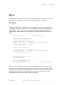
Mission
Our mission is to introduce High School students to the Computer Engineering profession
through an easy to use microcontroller kit. We will do this by designing a more
economical solution to what schools, Aptos High School in particular, is currently using.
Our microcontroller kit, named RoboBrain will be a much more powerful kit when
compared to our competitors. Parallax’s microcontroller kit, the “Board of Education,” is
what Aptos HS is currently using for their robotics project. We hope to change that.
Although it is geared towards High School Students, it can also be used by Computer
Engineers or Robot Hobbyists as a Development Board.
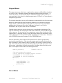
Most High School students do not have the slightest idea of what differentiates a
Computer Engineer from a Computer Scientist or an Electrical Engineer. This kit is
intended to cover all 3 aspects of these fields, with an emphasis on Computer
Engineering. It will cover the design layout and why certain IC parts were used where
they are.
This project will also cover some of the history, tools, and methods to help aide the user
in understanding the objectives of each lesson.
The goals of the second version of RoboBrain were to simplify the original design into a
more discrete IO system while adding potential for additional sensor inputs and control.
Version two is a redesign simply omitting unnecessary components and adding more
useful and optional functionality.
This entire project is non-proprietary, and does not have any bonds with other companies.
The compiler, text editor, and downloader are all freeware. All that we ask is that you do
not redistribute this product for profit.
RoboBrain©
University of California, Santa Cruz
2
RoboBrain User Manual
Rev. 4
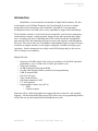
INTRODUCTION
5
ROBOBRAIN ASSEMBLY
6
PARTS
ASSEMBLY / SOLDERING
6
8
TURNING ON ROBOBRAIN AND PROGRAMMING
19
SYSTEM TOOLS
21
COMPILER
DOWNLOADER
INTEGRATED DEVELOPMENT ENVIRONMENT
COMPILING THE ROBOBRAIN LIBRARIES
COMPILING A PROGRAM WITH JEDIT
COMPILING A PROGRAM WITHOUT JEDIT
USING BATCH/SCRIPTS TO COMPILE YOUR CODE
DOWNLOADING A PROGRAM TO ROBOBRAIN WITH JEDIT
DOWNLOADING A PROGRAM TO ROBOBRAIN WITH FLASHMAGIC
TEST PROGRAM
21
21
21
21
22
22
25
25
25
27
SAMPLE PROGRAMS & LESSONS
27
IR INTENSITY
LCD
PLAY MUSIC
PROGRAMMABLE INTERRUPT BUTTONS
EXTERNAL PORT READING AND WRITING
INFRARED SENSORS
ROBOIR EXAMPLE I: DETECTING INFRARED
ROBOIR EXAMPLE II: MEASURING IR INTENSITY
ROBOIR EXAMPLE II: MEASURING IR INTENSITY
27
27
28
29
30
32
33
33
34
MOTORS
41
DC MOTORS
STEPPER MOTORS
SERVO MOTORS
41
42
42
FUNCTION INDEX
43
CONSTANT DEFINITIONS
TIME FUNCTIONS (TIME.H)
SERIAL I/O LIBRARY (SIO.H)
44
45
45
RoboBrain©
University of California, Santa Cruz
3
RoboBrain User Manual
Rev. 4
MOTOR FUNCTIONS (MOTOR.H)
LCD FUNCTIONS (LCD.H)
PIN I/O FUNCTIONS (IO.H)
I2C FUNCTIONS (I2C.H)
47
49
50
54
APPENDIX A – ROBOTS FOR COSMOS
58
PARTS
CHARACTERIZING THE IR SENSORS
58
60
RoboBrain©
University of California, Santa Cruz
4
RoboBrain User Manual
Rev. 4
Introduction
RoboBrain is a microcontroller kit intended for High School Students. The idea
was brought to us by William Thompson, and Cyrus Bazeghi. It involves a complex
design that involves interfacing a microcontroller with other ICs; incorporating a
development board or a kit that can be easily expandable to support other functionality.
The kit includes include a circuit board, the microcontroller, some discrete components,
an introductory manual, a sample program, along with any other parts that they might
need. Assembly will involve soldering some SOIC surface-mount and “through-hole”
parts onto the PCB, and connecting the proper resistive and capacitive loads throughout
the board. This will give the user a tremendous understanding of what is required to meet
certain noise margins, and why circuit design is important, in addition to being a great
experience. Surface mount parts are widely used in PCB designs and give the user an
idea of what goes on in industry.
Philips P89C668:
•
•
•
•
•
•
•
•
•
•
Speed up to 20 MHz with 6 clock cycles per machine cycle (40 MHz equivalent
performance); up to 33 MHz with 12 clocks per machine cycle
Fully static operation
64 KB of internal Flash Program ROM
On-chip Flash Program Memory with In-System programming
8 KB of internal RAM
Four 8-bit I/O ports
Three Counter/Timers
Full-duplex enhanced UART
I2 C serial interface
Programmable Counter Array (PCA)
o PWM
o Capture/compare
Functions will be called using high-level wrapper functions written in C and Assembly
language. All this functionality placed on a PCB with an easy use programming interface
will get the user up and running with the RoboBrain in no time.
RoboBrain©
University of California, Santa Cruz
5
RoboBrain User Manual
Rev. 4
RoboBrain Assembly
Parts
The following part list will help you construct your RoboBrain in no time. The parts are
categorized and some part reference numbers and/or surface mount sizes have also been
provided.
ICs
1
1
1
1
2
3
3
Linear Regulator 7805
Philips 8051 Microcontroller
Altera CPLD
MAX232I/SO Serial Transceiver
SN754410 Half H-Bridge Driver
PHILIPS PCF8591 8bit A/D converter
LMC6484 Quad Op Amp SOIC
DIGIKEY:LM7805CT-ND/TO-220
PHILIPS:P89C668
ALTERA:EPM7128S
DIGIKEY:296-6940-5-ND
DIGIKEY:296-9911-5-ND
DIGIKEY:568-1088-2-ND
DIGIKEY:LMC6484AIMX
Capacitors
2
7
22
1
1
27pF
10uF
.1uF
1uF
47uF 25V
Surface Mount 0805
Surface Mount 0805
Surface Mount 0805
Surface Mount 0805
Axial
470ohm
4.7Kohm
10Kohm
330ohm
100ohm
270ohm
100Kohm
47Kohm R_NETWORK_BUS_9
470ohm R_NETWORK_BUS_9
470ohm R_NETWORK_ISO_8
Surface Mount 0805
Surface Mount 0805
Surface Mount 0805
Surface Mount 0805
Surface Mount 0805
Surface Mount 0805
Surface Mount 0805
DIGIKEY:4310R-1-473-ND
DIGIKEY:4310R-1-471-ND
DIGIKEY:767-163-R470-ND
Green LED Surface Mount 0805
1N4001 DIODE Axial
1N5401 DIODE 3Amp Axial
1-Digit 7-Segment-Display
DIGIKEY:SML-LXT0805GW-TR
DIGIKEY:1N4001
DIGIKEY:1N5401
DIGIKEY:160-1575-5-ND
Resistors
3
8
10
10
1
6
6
3
1
1
Diodes
9
18
1
1
RoboBrain©
University of California, Santa Cruz
6
RoboBrain User Manual
Rev. 4
Switches
3
1
1
1
Tact Pushbutton SPST
SW DIP-8
SW DIP-4
POWER SW DPST
DIGIKEY:CT2098MS-ND
DIGIKEY:CT2094MS-ND
DIGIKEY:P8102S-ND
Sensors and Emitters
4
4
6
IR emitter
IR sensor
Line detection Sensor/Transducer
DIGIKEY:QED523-ND
DIGIKEY:QSD733-ND
DIGIKEY:QRB1114-ND
Jacks and Sockets
1
1
1
1
1
PJ-102BH DC POWER JACK
3 Input Terminal Blockk
FEMALE D-SUB9 Serial Jack
PLCC 84pin Thru Hole TO Socket
PLCC 44pin Thru Hole TO Socket
JAMECO:104951
DIGIKEY:ED80027-ND
DIGIKEY:ED80024-ND
Headers and Other Parts
1
2
1
1
1
2
1
4
40pin Male DIP Header
20pin Male SIP Header
20pin Female SIP Header
PIEZO SPEAKER
Regulator Heatsink
Motor Driver Heat sink
20Mhz Crystal
FF Spacers
JAMECO:207950
Staver V7 Heatsink
DIGIKEY:CTX062-ND
Optional LCD
1
1
10Kohm Trimpot
LCD 24 character x 2 lines
OPTREX:DMC24201
The RoboBrain, along with having simplified access to the microprocessor’s pins, will
have built-in drivers to operate several outside devices:
•
•
•
•
•
•
•
Motors (DC, Servo, Stepper)
IR Sensors
UART
I2C
Basic sound via a Piezo speaker
Character LCD
IR communication
RoboBrain©
University of California, Santa Cruz
7
RoboBrain User Manual
Rev. 4
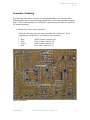
Assembly / Soldering
The following instructions will guide you through RoboBrain v2.1 board assembly.
Following these step by step instructions should allow for the easiest possible assembly.
Steps 3 and 5 in this assembly are OPTIONAL. Optional steps need not be considered
for minimal operation.
1) Bottom side surface mount capacitors.
Solder the following capacitors onto the bottom side of the board. These
components are un-polarized, so orientation does not matter.
•
•
•
•
Blue:
Pink:
Green:
Red:
100nF Ceramic Capacitor (18)
27pF Ceramic Capacitor (2)
10uF Ceramic Capacitor (7)
1uF Ceramic Capacitor (1)
Figure 1: Bottom side
RoboBrain©
University of California, Santa Cruz
8
RoboBrain User Manual
Rev. 4
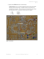
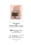
2) Bottom side surface mount Resistors / IC’s.
Solder the following resistors on the bottom side of the board. The 0805 resistors
are un-polarized, so orientation does not matter. The Isolated resistor network
package should be oriented with pin1 to the left side. The Max232 package
should be oriented with pin1 on the north side.
•
•
•
•
•
Blue:
Pink:
Dark Green:
Red:
Light Green:
4.7k! (4)
100! (1)
470! (2)
470! Isolated Network Resistor Package (1)
Max232 (1)
Figure 2: Bottom side
RoboBrain©
University of California, Santa Cruz
9
RoboBrain User Manual
Rev. 4
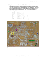
3) Bottom side OPTIONAL surface mount Resistors.
If line detection sensors are desired, populate the bottom of the board with the
following surface mount resistors. The 0805 resistors are un-polarized, so
orientation does not matter. If line detection is not desired, the system will run
fine independent of these components, and this step can be skipped.
•
•
•
Blue:
Red:
Green:
270! (6)
10k! (2)
100k! (6)
Figure 3: Bottom Side
RoboBrain©
University of California, Santa Cruz
10
RoboBrain User Manual
Rev. 4
4) Top side surface mount Capacitors, LEDs, IC’s and resistors.
Solder the following surface mount components onto the top side of the board.
The 8 LED’s should be placed with Anode south, and Cathode north. The single
LED should be oriented with Anode on the right and Cathode on the left. The
capacitors and resistors are un-polarized. The A to D Converter should be
oriented with pin1 left.
•
•
•
•
•
•
•
Dark Green:
Light Green:
Red:
Blue:
Pink:
Purple:
Yellow:
330! Resistor (4)
SM LED’s (9)
10k! Resistor (4)
100nF Ceramic Capacitor (3)
4.7k! Resistor (4)
470! Resistor (1)
PCF8591 A to D converter (1)
Figure 4: Top Side
RoboBrain©
University of California, Santa Cruz
11
RoboBrain User Manual
Rev. 4
5) Top side OPTIONAL Surface Mount / Thru-Hole components.
If line detection is desired and step 3 was performed, populate the top side of the
board with the following components. If line detection is not desired, the system
will run fine independent of these components, and this step can be skipped. The
top A to D should be oriented with pin1 left. The bottom one should be oriented
with pin1 to the right. For easy chip swapping, populate a 14pin Dip socket
where the Op-amps go. Observe the location of the square pin hole for
Socket/Op-amp and Resistor network orientation.
•
•
•
•
•
Dark Green:
Red:
Yellow:
Blue:
Light Green:
330! Resistor (6)
10k! Resistor (4)
PCF8591 A to D converter (2)
14pin DIP socket or LMC64/84 op amp (2)
47k! Network Resistor package (1)
Figure 5: Top Side
RoboBrain©
University of California, Santa Cruz
12
RoboBrain User Manual
Rev. 4
6) Top side Thru-hole Motor Sockets / Power Source Diodes.
The following components must now be soldered to the top side. Parts that will
later be added will obstruct your ability to solder these components later. The
two 1N1004 diodes should both be oriented with anode left and Cathode right.
The 1N5004 diode should be placed with Anode north and Cathode south. For
easy chip swapping, populate a 16pin Dip socket where the motor drivers go.
Observe the location of the square for Socket/Motor-Driver orientation.
•
•
•
Red: 1N1004 diode. (2)
Blue: 1N5004 diode. (1)
Green: 16pin Dip Sockets or Motor Drivers (2)
Figure 6: Top Side
RoboBrain©
University of California, Santa Cruz
13
RoboBrain User Manual
Rev. 4
7) Bottom Side Thru-Hole Components.
Now populate the remainder of the bottom Thru-Hole components. All diodes
shown here are optional, as they provide Induction Kick protection for the motor
drivers. The system will work without them. Pay attention to the diode
orientation. Square pin hole is Anode, round is Cathode.
•
•
•
•
•
Red:
Blue:
Pink:
Maroon:
Green:
1N1004 Diode (16)
AC/DC Jack (1)
DSUB-9 Serial Jack (1)
47k! Network Resistor (2)
470! Network Resistor (1)
Figure 7: Bottom Side
RoboBrain©
University of California, Santa Cruz
14
RoboBrain User Manual
Rev. 4
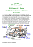
8) Top Side Thru-Hole Components
The following components make up the remainder of the required top-side ThruHole components. When placing the Regulator, be sure to place it with the
heat-sink to ensure a good fit. Pin 1 on the 44pin socket should face North. Pin 1
on the 84 pin socket should face Right. Both the Power and Pushbutton switches
have no relevant polarity.
•
•
•
•
•
•
•
•
•
•
•
•
Red:
Light Blue:
Blue:
Dark Blue:
Light Green:
Dark Green:
Pink:
Purple:
Yellow:
Black:
Grey:
Maroon
Power Switch (1)
44pin PLCC CPU Socket (1)
84pin PLCC CPLD Socket (1)
8MHz Crystal (1)
10-DIP Switch Block (1)
4-DIP Switch Block (1)
Momentary Pushbuttons (3)
47uF Radial Capacitor (1)
7805 T0-220 Power Regulator (1)
Power Input Terminal Block (1)
7-Seg (1)
Piezo Speaker (1)
Figure 8: Top Side
RoboBrain©
University of California, Santa Cruz
15
RoboBrain User Manual
Rev. 4
9) Top Side Steak Headers & LCD Trimpot
Solder male and female steak headers to the Top side of the board. Some of these
headers are optional.
•
•
•
•
•
•
•
•
Red:
Blue:
Green:
Yellow:
Pink:
Purple:
Black:
Grey:
6pin Male SIP header (2)
3pin Male SIP header (2)
2pin Female SIP header (8)
4pin Female SIP header (1)
6x2pin Male DIP header (2, Line Detection optional)
7x2pin Male DIP header (1, LCD optional)
10k! Trimpot (1, LCD optional)
5x2 Male DIP header (1, CPLD JTAG optional)
Figure 9: Top Side
RoboBrain©
University of California, Santa Cruz
16
RoboBrain User Manual
Rev. 4
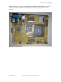
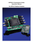
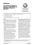
Following step 9 you are have now completed your RoboBrain kit assembly. Here are
some views on how the board may look. In these images, optional parts were not
populatd.
Figure 10: Assembled Top Side
RoboBrain©
University of California, Santa Cruz
17
RoboBrain User Manual
Rev. 4
Figure 11: Assembled Bottom Side
RoboBrain©
University of California, Santa Cruz
18
RoboBrain User Manual
Rev. 4
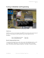
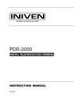
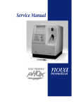
Turning on RoboBrain and Programming
Figure 12: Power and Programming Switches
Main Power:
Main Power can be activated using the large DPST Power Switch on the top left corner of
the board. The main power switch controls DC power to the digital devices on
RoboBrain.
Power Switch Depressed (down):
Power Switch Released (up):
Power On
Power Off
Board Configuration Dip Switches:
If you look near the Main Power switch on the top side of the RoboBrain board, you will
see 4 Dip Switches. Dip Switch 1 is a no connect. Dip Switch 2 and 3 select motor
power. Dip switch 4 selects Program or Run mode. See Figure 12 for quick reference.
RoboBrain©
University of California, Santa Cruz
19
RoboBrain User Manual
Rev. 4
Program Select Mode:
Dip Switch 4 On:
Dip Switch 4 Off:
Program mode
Run mode
A note about Program mode: A reset is required to place RoboBrain in “Program
Mode”. When programming, you may choose to switch off dip switches 2 and 3. That
way, it is ensured that the motor power is disconnected when programming and you will
not have to worry about running out of power.
Motor Power Source Selection:
There are two sources of power for the RoboBrain motors. The first source is tied to
main power. To enable/ disable main power driving the motors use Dip Switch 2.
Dip Switch 2 On:
Dip Switch 2 Off:
Motor power taken from main power source.
Motors disconnected from main power.
The second motor power source comes from an alternate power source. To enable/
disable alternate power driving the motors use Dip Switch 3.
Dip Switch 3 On:
Dip Switch 3 Off:
Motor power taken from alternate power source.
Motors disconnected from alternate power.
It is safe for both Dip Switches 2 and 3 to be “On” simultaneously. In this case motor
power will be driven by the highest supplying source. Both power sources are protected
with reverse-bias diodes (see figure 6).
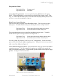
A note about motor power sources: The terminal block at the top of the board handle’s
connections to power. The left terminal is for main power, middle is for ground, and
right is for alternate motor power. Use the middle ground terminal for both power supply
grounds. See Figure 13 for more details.
Figure 13: Power source terminal block
RoboBrain©
University of California, Santa Cruz
20
RoboBrain User Manual
Rev. 4
System Tools
Compiler
The compiler that RoboBrain uses is SDCC (Small Device Compiler C). It is
freeware and is compatible on both Windows and UNIX environments.
Documentation can be found online at http://sdcc.sourceforge.net/.
Downloader
We use the Flash Magic downloader in order to download the code to the board
through ISP (In System Programming). This technique is a lot easier than having to
burn directly to the chip using an EEPROM Burner.
Integrated Development Environment
You can use any text editor that you are comfortable with. We offer you jEdit, which
is a Java based text editor that has a lot of cool features. It embeds the compiler into
the editor, so with a click of a button, you can compile and download your code.
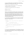
Compiling the RoboBrain Libraries
Before you begin compiling and downloading programs of your own to the
RoboBrain, you first need to compile the RoboBrain libraries, these are located in the
Lib\Robobrain Final\ directory on the RoboBrain CD. Copy all these files into the
same directory as your program, this will ensure that the compiler will know where to
find them.
Once all the library files are copied over, all that is left is to compile them, producing
the object code to combine with your program. Each library is made up of a C source
code file (.C) and a header file (.H). The header file can be looked at as the table of
contents of the C source code file. Open the jEdit program and then open all the C
source code files of the libraries you plan to use, if you are not sure what libraries
you’ll need, we recommend simply compiling all the libraries now, saving you the
trouble of having to do it later.
When the C source code file is open, you can compile it by clicking the “Compile”
button, represented by the “down arrow” icon in the toolbar, see Figure 5. Clicking
this button will bring up a dialog box whose settings that can be ignored for now, just
hit the ‘OK’ button. Some messages will come up on in jEdit’s status window saying
that the files were compiled successfully. The object file for the library you just
compiled has been created and is stored in the appropriate .rel files in your program
directory. Once all the necessary libraries have been compiled, you can continue on
to compile your program.
RoboBrain©
University of California, Santa Cruz
21
RoboBrain User Manual
Rev. 4
Compiling a Program with jEdit
Using the jEdit software that is included, you can compile and download a program to
your RoboBrain. Let’s set through a simple example.
Start by opening jEdit and creating a new file. For a minimum amount of code, you
need the following to be entered;
#include “sdcc668.h”
int main(void)
{
return 0;
}
This program does absolutely nothing but gives some base code to start working with.
All your program code is to go in between the two curly braces, ‘}’ and ‘{‘, after int
main(void). Now let’s compile this program.
Go to the toolbar and click the run program button, symbolized by the running man
icon, shown in Figure 5. From there, a window will open up and show a series of
check marks. None of these check marks need to be checked at this point. Once you
begin making use of the RoboBrain libraries, you will check the boxes of the libraries
you are using. Each check box corresponds to a RoboBrain library. If you are using
a function from a library, check the appropriate box (do not forget to add the #include
statement for that library as well). After looking over all the libraries to include, hit
“OK.” The code should compile successfully and the output of the compiler is shown
in the bottom pane of the editor.
Should any syntax errors occur, the source of these errors can be found by clicking
the “Error List” button in the bottom pane of the jEdit window.
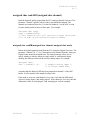
Compiling a Program without jEdit
To begin compiling and downloading for the RoboBrain without jEdit, follow the
instructions below. We will implement a rather simple program that will display the
hex value being represented on the INPUT SWITCHES located on the RoboBrain.
1. Open a DOS command-line or in any Windows platform, create a new directory
on the local hard disk. For the purposes of this exercise, we will name the folder
“testRB”. To create a folder in DOS, type: mkdir <folder_name>
RoboBrain©
University of California, Santa Cruz
22
RoboBrain User Manual
Rev. 4
2. Copy over the libraries (stdio.h, sio.h, sdcc668.h) that were included in the
documentation in to the folder just created “testRB”. This is necessary to interface
the Philips chip, and its surrounding interface components.
3. Open up a text editor, and create a new file, “test.c”. This will be the file
containing the program code for the RoboBrain.
4. Include the necessary libraries in the test.c file. To do this, type:
#include
#include
#include
#include
"stdio.h"
"sio.h"
"io.h"
"sdcc668.h"
This piece of code will include the stdio.h library which contains printf(), and other
useful functions for displaying data from the RoboBrain. sio.h is the library that we
created in order to input and output data to and from the RoboBrain. The sdcc668.h
library should never be modified. It uniquely maps out all the special function
registers inside of the Philips chip, and the external ports that the user can interface
with. The special function registers include the location of some of the features
embedded inside of the chip, for example the Internal Timers/Counters, I2C protocol,
and Pulse Width Modulation registers.
5. Create the instance of code that will be executed. For the purpose of the sample
program, the following code should display the value represented from the INPUT
switches on the 7-segment LED bar.
int main() {
/* Initialize UART to display welcome screen in HyperTerminal */
initUART();
cls();
//clear HyperTerminal screen
printf(“Test program without using jEdit\r\n”);
/* Infinite while loop to continuously read the input switch and
change the values on the 7-segment LEDs simultaneously */
while(1) {
seg_driver(SEG_R, IN_SW);
}
return 0;
}
6. Now it is time to compile and download the code to the RoboBrain. There are two
ways to compile code for the RoboBrain. First way will compile the code without the
use of a batch file (script). The second way will save time on typing at the command
line, and will use the batch file.
RoboBrain©
University of California, Santa Cruz
23
RoboBrain User Manual
Rev. 4
At the DOS command line, change directory to the folder where your program code
“test.c” is stored. Before we can compile the entire code for downloading to the
RoboBrain, we must compile the individual libraries used in the program code. With
the exception of libraries that are not paired with *.c files, all other libraries must be
precompiled before test.c can be compiled and downloaded. To compile a library file,
at the command prompt, type:
sdcc -c --model-large sio.c
This line of code calls the compiler with the option “-c” to compile the file “sio.c”. If
the compile is successful, it will create a “sio.rel” file that will be used to compile the
entire program code. The option --model-large tells the processor that it is using a
large memory map. It is not critical to know what the difference between a small and
large memory map is, but you can read more about it in the SDCC and Philips
P89C668 Reference Manuals.
7. Compile the io.c library in the same manner as the sio.c library and we can now
compile the test.c program code. To do this, type the following:
sdcc --model-large --xram-size 0x1eff --xram-loc 0x0100 --code-size 0xffff --stack-loc 0x1000 test.c sio.rel io.rel
This piece of code is quite a handful and tedious to type out every time to compile
code, so that is why we will make a batch (script) file that will automate all the typing
for us. The compiler is called with several options, which specify to the processor
how to utilize the embedded memory.
Options:
--xram-size 0x1eff : Lets the microcontroller know how much internal memory
can be used for internal RAM. The P89C668 has 8k of
internal memory, hence 0x1eff in hexadecimal equals 8k in
decimal.
--xram-loc 0x0100 : Indicates where in RAM the dynamic variables can be
stored.
--code-size 0xffff
: Lets the microcontroller know how much internal
memory can be used for internal ROM. The P89C668 has
64kb of ROM available for program code.
--stack-loc 0x1000 : This places the system stack at address 0x1000
After all of the options have been set, include the program file that contains the
main() definition, in this case, “test.c”. Next, include all the precompiled libraries
required to run the test program, “sio.rel” and “io.rel”. If there are multiple
precompiled header files, you must include the other *.rel files at the end of the
compile command (i.e. sdcc (options) test.c sio.rel motor.rel time.rel).
RoboBrain©
University of California, Santa Cruz
24
RoboBrain User Manual
Rev. 4
Using batch/scripts to compile your code
Create a new file called “make.bat”. Open this file for editing, and insert all the code
that was required for compiling the RoboBrain code into this file. For example:
sdcc -c --model-large sio.c
sdcc -c --model-large io.c
sdcc --model-large --xram-size 0x1eff --xram-loc 0x0100 --code-size 0xffff --stack-loc 0x1000 test.c sio.rel io.rel
Save and close the file. You can now either double click this file in Windows, or
execute it at the command prompt by typing in the filename, make.bat. It will execute
each line of code as if you had typed it. If the program code has compiled correctly, a
“test.ihx” would have been created. This is the file you will use to download to the
RoboBrain board.
Downloading a Program to RoboBrain with jEdit
Once you have successfully compiled a program, it should have produced an Intel
Hex File (.ihx), the format that is readable by RoboBrain’s Philips microcontroller.
This can then be sent to the board via a serial cable. To download to the board, click
the icon with the piece of paper and the running man on it. Select the COM port that
is hooked up to RoboBrain and click “OK.” Be sure that no other programs are using
the serial port, such as HyperTerminal; that will cause an error programming. Figure
6 shows the download and compile buttons.
Figure 6. Library Compile, Compile, and Download Buttons in jEdit
After programming is complete, HyperTerminal can be used to view output from the
serial port.
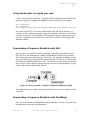
Downloading a Program to RoboBrain with FlashMagic
Now we can download to the RoboBrain using FlashMagic, but first we need to setup
the application to interface with RoboBrain.
RoboBrain©
University of California, Santa Cruz
25
RoboBrain User Manual
Rev. 4
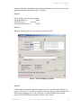
Open the application FlashMagic and set these parameters in the specific boxes in the
application window. Reference Figure 7 for help.
In box 1
Set the COM port to the proper setting.
Set the Baud Rate to:
38400
Set the Device to:
89C668
Set the Oscillator Freq. to:
20.000
In box 2
Mark the checkbox that says “Erase blocks used by Hex File”.
Figure 7. The FlashMagic program
In box 3
Click the Browse button to search for the test.ihx file. You must change the files of
type to “All files (*.*)” in order to search for *.ihx files. After you have found the file
in the Browse Dialogue box, click “Select File”. Set the RoboBrain for program
mode, hit the RESET button, and then click the “Start” button.
RoboBrain©
University of California, Santa Cruz
26
RoboBrain User Manual
Rev. 4
After the RoboBrain has been programmed, you can remove the Program jumper, and
reset the RoboBrain. The RoboBrain should now be programmed and running the
executed code in main(). You can open up a HyperTerminal session, and see the text
that should be printed at the top of the screen, “Test program for compiling and
downloading with out jEdit”.
Test Program
Once all the components have been placed on the board, testing each of RoboBrain’s
various capabilities is required. Place the board in program mode and run the
“build.bat” shortcut in the RoboBrain “test program” program directory and
download the resulting .ihx file to the RoboBrain. This runs a program that runs
through all the components on the board and displays output via the serial port. This
output can be viewed through HyperTerminal on the proper COM port at 19200 baud.
Sample Programs & Lessons
IR Intensity
This sample program will turn on both Infrared emitters and read in the analogue
voltage from that is received from the Photo Darlington receivers. This program
makes use of the Analog-to-Digital converter and samples the analog voltage. This
sample program can be found in the “Sample Programs” folder of the RoboBrain CDROM. Simply load the main.ihx file from the “IR Intensity Ver. 1” folder into
FlashMagic, and download it to your board.
LCD
This sample program will initialize and print “Hello World!!!” to the LCD. It will
then accept user input and echoes characters that are inputted from HyperTerminal.
This sample program can be found in the “Sample Programs” folder of the RoboBrain
CD-ROM. Simply load the main.ihx file from the “LCD Ver. 1” folder into
FlashMagic, and download it to your board.
If you want to get the same LCD (24 characters by 2 lines) that we used to ensure
compatibility with RoboBrain, get LCD part number: EDT# EW24208YLY. This
costs about $12 and can be found at allelectronics.com at the URL or by the Catalog #
LCD-69:
http://www.allelectronics.com/cgi-bin/category.cgi?category=365&item=LCD69&type=store
RoboBrain©
University of California, Santa Cruz
27
RoboBrain User Manual
Rev. 4
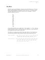
Play Music
Playing a song on your RoboBrain is simple by using the following code. The time
library contains definitions of frequencies for five octaves (0 – 5) of musical notes.
The letters represent the musical notes values for notes A through G. They are
defined as follows for octave 0:
A0
A0s
B0
C0
C0s
D0
D0s
E0
F0
F0s
G0
G0s
For any other the other octaves, replace the ‘0’ with a number 1 – 5. The ‘s’ after the
numbers represents a sharp, or half a step above the current note. These can be used
to in conjunction with two arrays to play a tune:
First define two constant arrays outside of the main() function. One with the notes
you want to play, and the second with how long you want to play them (in ms):
const int song[]
= {E4, D4, E4, A4, F4, E4, F4, E4, D4, F4, E4, F4,
A4, D4, C4, D4, D4, B4, D4, C4, B4, C4, D4,
C4, D4, E4, D4, C4, B4, A4, F4, E4, 0};
const int dur[] = {200, 150, 400, 800, 200, 150, 200, 200, 800, 200,
150, 400, 800, 200, 150, 200, 200, 200, 200,
600, 200, 150, 600, 200, 150, 200, 200, 200,
200, 400, 400, 1000, 1000};
RoboBrain©
University of California, Santa Cruz
28
RoboBrain User Manual
Rev. 4
Next, inside the main() function, define an integer, i, and using a loop and the
freq_out() function, step through the arrays:
int main(void)
{
int i;
for(i = 0; i < 32; i++)
{
freq_out(song[i], dur[i]);
}
}
return 0;
The 32 in the for loop represents the number of notes to play. You can replace this to
match the number of notes in your song. This loop plays one note for a certain period
of time and then continues to the next one and then plays that for the specified period
of time and so forth. This particular example plays “Final Countdown,” by Europe.
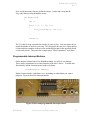
Programmable Interrupt Buttons
On the bottom left hand side of the RoboBrain board, you will see two buttons.
These can be programmed to execute functions of the user’s choice. To enable this
functionality, run the function located in the io.h library:
initINT(button number);
Replace button number with either 0 or 1, depending on what button you want to
program. Figure 8 shows the interrupt buttons.
Figure 8. Reset and programmable interrupt buttons
RoboBrain©
University of California, Santa Cruz
29
RoboBrain User Manual
Rev. 4
Next, to define functionality for the button, you need to write an interrupt service
routine. This is a function that gets called every time the button is pressed. For this
the following code is needed:
void extINT0(void) interrupt 0
{
//place code here for button 0
}
void extINT1(void) interrupt 2
{
//place code here for button 1
}
Once you have loaded your RoboBrain with this new code, every time you press the
button you programmed, your function will get called.
External Port Reading and Writing
The RoboBrain is equipped with several on-board ports that the user can use to run
sample programs on. The user has access to a dual 7-segment LED, an 8-INPUT
toggle switch, 8-OUTPUT SMT (Surface Mount) LEDs, LCD, 8-INPUT Proto-Area,
8-OUTPUT Proto-Area, and an “Extra” Port to be used for on-board IR and motor
control.
Being able to interface these ports is helpful for easy expansion of a robot module.
Particularly when trying to read in the INPUT Proto-Area and assigning the
designated OUTPUT ports. The user should only be able to READ OUTPUT ports,
but the compiler will not prevent you from reading the OUTPUT ports. Like wise, the
user should not be able to write to an INPUT port, but the compiler will not restrict it
from happening.
RoboBrain©
University of California, Santa Cruz
30
RoboBrain User Manual
Rev. 4
In the RoboBrain library file, the address for the external ports have been statically
defined the location in memory where the user should be able to READ and WRITE
the corresponding register to the PORT.
PORT
Pseudo-Name
Register
Address
1
2
3
4
5
6
7
8
LED (SMT)
INPUT Switch
7-Segment A
7-Segment B
OUTPUT Proto-Area
INPUT Proto-Area
LCD Module
EXTRA
LED
IN_SW
SEGA
SEGB
PROTOA
PROTOB
LCD
EXTRA
0xFC00
0xFC80
0xFD00
0xFD80
0xFE00
0xFE80
0xFF00
0xFF80
How to READ a PORT
(INPUT Switch, INPUT Proto-Area)
1) Declare an 8-bit register, preferably an unsigned char.
(i.e. unsigned char SWITCH; )
2) Assign the 8-bit register to one of the INPUT registers defined in the
RoboBrain library.
(i.e. SWITCH = IN_SW; )
Following this technique will successfully allow the user to read input from the PORT,
and store it into an 8-bit register, which can be processed elsewhere in the user’s code.
How to WRITE to a PORT
(LED, 7-Segments, OUTPUT Proto-Area, EXTRA)
1) Declare an 8-bit register, preferably an unsigned char.
(i.e. unsigned char smtLED; )
2) Initialize the 8-bit register to some value that will be eventually written to the
PORT.
(i.e. smtLED = 0x55; )
3) Assign the PORT register that is defined in the RoboBrain library to the 8-bit
register that was declared in STEP 1.
(i.e. LED = smtLED; )
Following this technique will successfully allow the user to write to the OUTPUT PORT.
Realistically, you can omit the 8-bit data register, and write directly to the PORT.
(i.e. LED = 0x55; )
RoboBrain©
University of California, Santa Cruz
31
RoboBrain User Manual
Rev. 4
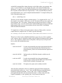
Infrared Sensors
The RoboBrain supports at least 2 Infrared Emitting Diodes (IRED) located on the Far
East side of the board (next to INPUT Switch and LCD Header).
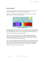
Infrared is a type of light with a wavelength rated between 700nm to over 1200nm.
Figure 9 shows where IR is on the light spectrum.
Figure 9. Light Spectrum
The IR Emitting Diodes in your kit emit at 840nm. They are paired up with a matching
Photo Darlington receiver which is set to receive IR light at that wavelength. We decided
to use Photo Darlington’s because it has a current gain of around 1000, enabling us to
receive IR at a much stronger signal at a further range.
The emitter acts much like a diode, since it is an LED (Light Emitting Diode). By
allowing current to flow from the Anode to the cathode of the LED, infrared light is
emitted from the clear dome. Don’t worry if you can’t see anything, this is because the
wave length of IR can not be seen by the human eye.
The receiver acts as a Bipolar-Junction Transistor (BJT). If you are unfamiliar with BJTs,
don’t worry, for the purposes of this section we do not need to go into detail on how they
work. The intensity of IR light at the base of the BJT (lens of the Photo Darlington)
determines how much current will flow from Collector to Emitter, thus allowing the
voltage at the Collector to be seen at the emitter.
RoboBrain©
University of California, Santa Cruz
32
RoboBrain User Manual
Rev. 4
Figure 10. IRED and Photo Darlington Schematic
On the RoboBrain board, we put a limiting current resistor across the emitter to ground so
that we cam measure the voltage at the emitter. Much like any other source of light, IR
does not reflect well off of dark/black surfaces. In example II of this section, you will
sample the voltage using an ADC. By measuring this voltage, we can determine the
strength of the IR signal. The example given will allow you to bounce IR off of an object,
and in essence, determine how far away your RoboBrain is away from the object.
RoboIR Example I: Detecting Infrared
Materials:
1 IRED
1 Photo Darlington
1 Jumper Wire (not included)
This experiment demonstrates how to determine when the Photo Darlington has reached a
TTL logic level on the INPUT Proto-Area PORT.
1) Connect 1 IRED and matched Photo Darlington pair to the RoboBrain.
2) Jumper the output of the Photo Darlington to the Proto area of the RoboBrain.
3) In software, poll the INPUT PORT to determine when the Photo Darlington has
reached a logic level HIGH.
RoboIR Example II:
Materials:
1 IRED
1 Photo Darlington
Measuring IR Intensity
1 I2C ADC
1 Shunt Jumper
By putting a jumper across the Photo Darlington output and to the I2C ADC, we can
sample the intensity of the IRED. Sample code has been produced to already interface
with the I2C ADC, so that you can call a function to immediately sample the IR for you.
1) Connect 1 IRED and matched Photo Darlington pair to the RoboBrain.
2) Jumper the output of the Photo Darlington to the Proto I2C ADC header.
RoboBrain©
University of California, Santa Cruz
33
RoboBrain User Manual
Rev. 4
3) In software, call the function “readADC(0x00);”. This will read the IRED intensity
from the Photo Darlington near the INPUT Switch.
RoboIR Example II:
Measuring IR Intensity
If you want to use the built-in IR connections on the RoboBrain, it is easy to do so;
simply hook up the IR receiver and transmitters to your RoboBrain and write some code
to use them. The IR sensor in the top right will here after be referred to as the left IR
sensor (sensor number 2 in code) and the one in the bottom right will here after be
referred to as the right IR sensor (sensor number 1 in code), see Figure 11 for details.
Make sure you connect both the IR sensors and the Voltage Ref. pins on the ADC
connector (see section below for how to do this) in order to have the sensors function
properly. Note that the anode or positive lead of the IR receiver and transmitter is the
longer of the two leads and will go in the bottom holes of the IR port.
RoboBrain©
University of California, Santa Cruz
34
RoboBrain User Manual
Rev. 4
Below is some code that can get you started: this program will read in the status of the
left and right IR receivers and display the output on the row of LEDs at the bottom right
of RoboBrain. The more LEDs that light up, the closer the object is to the IR sensor.
#include “motor.h”
#include “ir.h”
#include “i2c.h”
int main()
{
unsigned char irLeft, irRight;
initI2C();
//initialize the i2c bus
//loop infinitely
while(1)
{
//read the status of the IR receivers
irLeft = readIR(2);
irRight = readIR(1);
//provide feedback on the LEDs
intensityLED(irLeft | irLeft);
}
return 0;
}
RoboBrain©
University of California, Santa Cruz
35
RoboBrain User Manual
Rev. 4
These 3 examples should provide you with enough background to interface IR on your
own RoboBrain project.
Terminology
ADC – Analog-to-Digital Converter
BJT – Bipolar Junction Transistor
I2C – 2 wire communication interface
IR - Infrared
IRED – Infrared Emitting Diode
RoboBrain©
University of California, Santa Cruz
36
RoboBrain User Manual
Rev. 4
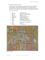
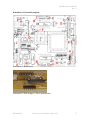
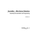
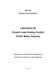
RoboBrain v2.1 Board Description
Description 1: Board layout
Description 2: B DC/Stepper, C Servo motor headers
RoboBrain©
University of California, Santa Cruz
37
RoboBrain User Manual
Rev. 4
A)
Line Detection Emitter / Sensor Headers
QRB1114 #1, 4 (Front and Rear Right Line Detector)
Pin 1:
Emitter Anode (+)
Pin 2:
Sensor Collector (5.0v)
Pin 3:
Emitter Cathode (-)
Pin 4:
Sensor Emitter
QRB1114 #2, 5 (Front and Rear Center Line Detector)
Pin 5:
Emitter Anode (+)
Pin 6:
Sensor Collector (5.0v)
Pin 7:
Emitter Cathode (-)
Pin 8:
Sensor Emitter
QRB1114 #3, 6 (Front and Rear Left Line Detector)
Pin 9:
Emitter Anode (+)
Pin 10:
Sensor Collector (5.0v)
Pin 11:
Emitter Cathode (-)
Pin 12:
Sensor Emitter
B)
DC/Stepper Motor Headers
•
•
C)
DC motor:
Pin 1:
Pin 4:
Pin 2, 3, 5, 6:
Stepper Motor:
Pin 1:
Pin 2:
Pin 3:
Pin 4:
Pin 5, 6:
Coil 1A
Coil 1B
Coil 2A
Coil 2B
Common
Servo Motor Headers
Pin 1:
Pin 2:
Pin 3:
D)
Coil 1
Coil 2
NC
Control
VCC
GND
Altera MAX 7000 CPLD JTAG Header
Pin 1:
Pin 2, 10:
Pin 3:
Pin 4:
Pin 5:
Pin 9:
Pin 6, 7, 8:
RoboBrain©
TCK
GND
TDO
Vcc 5.0v
TMS
TDI
NC
University of California, Santa Cruz
38
RoboBrain User Manual
Rev. 4
E)
LCD / ProtoBoard Header
Pin 1:
Pin 2:
Pin 3:
Pin 4:
Pin 5:
Pin 6:
Pin 7:
Pin 8:
Pin 9:
Pin 10:
Pin 11:
Pin 12:
Pin 13:
Pin 14:
F)
GND
Vcc 5.0v
LCD Intensity
A0
!RD/WR
LCD Chip Select
Data0
Data1
Data2
Data3
Data4
Data5
Data6
Data7
Power / I2C Access Header
Pin 1:
Pin 2:
Pin 3:
Pin 4:
G)
SDA
SCL
GND
Vcc 5.0v
Control Dip Switch Block
SW 1:
SW 2:
SW 3:
SW 4 (PSEN):
H)
Not Used
ON: VCC MOTOR = 5v Regulated
ON: VCC MOTOR = PowerBlock Pin3
ON: Program Mode OFF: Run Mode
Power Block Terminal
Pin 1:
Pin 2:
Pin 3:
Main Power
Common GND (digital and motor)
Motor Power
I)
AC/DC Power Barrel Jack
J)
Serial Connector
K)
Interrupt Pushbutton #1
L)
Interrupt Pushbutton #0
M)
Master Reset Pushbutton
RoboBrain©
University of California, Santa Cruz
39
RoboBrain User Manual
Rev. 4
N)
Front Left Emitter/Sensor
Front of Board !
Sensor +
Emitter -
Sensor -
O)
Emitter +
Front Right Emitter/Sensor
Front of Board !
Emitter +
Emitter -
Sensor +
P)
Sensor 1
Left Emitter/Sensor
Front of Board !
Sensor +
Emitter -
Sensor -
Q)
Emitter +
Right Emitter/Sensor
Front of Board !
Sensor +
Sensor -
Emitter +
RoboBrain©
Emitter -
University of California, Santa Cruz
40
RoboBrain User Manual
Rev. 4
Motors
The RoboBrain has support for DC motors, stepper motors, and servo motors via various
motor ports located at the top of the board (Description Image 2 on page 39).
DC Motors
To connect a DC motor to RoboBrain, simply connect the motor’s two terminals to the
Coil A and Coil B pins. There are two sets of coil pins so you can connect 2 DC motors
to RoboBrain. The code necessary to get the motor doing anything is listed below,
further details on these functions can be found in the function index at the end of this
guide.
enable_motors();
//enable motors
//start moving the motors
//this runs MOTORA port
//until the motor is stopped
//runs the motor full speed in reverse direction
motor_speed(MOTORA, -100);
//this runs MOTORB port
//until the motor is stopped
//runs the motor 50% speed in forward direction
motor_speed(MOTORB, 50);
//move around for a bit
//and then stop
motor_speed(MOTORA, 0);
motor_speed(MOTORB, 0);
//stop both motors
The motor_speed() function is the heart of the functionality for the DC motors. It uses
I/O pins with a voltage difference across them to control the motor. The signals of the
two motor pins are swapped to change direction. They are made the same value to stop
the motor due to the lack of a voltage difference across the two pins. Pulse-width
modulation (PWM) is used for speed control of the motors.
RoboBrain©
University of California, Santa Cruz
41
RoboBrain User Manual
Rev. 4
Stepper Motors
The stepper motors are a little more complicated to connect to the RoboBrain board but
are easier to code. RoboBrain supports both unipolar and bipolar stepper motors. To
connect the motor, you first need to find out what kind of stepper motor you have. If
your motor has 4 wires, then it is a bipolar stepper motor. If it has 5 or 6 wires, then it is
a unipolar stepper motor.
For a bipolar motor, there are two coils without any common tap for the coils; this means
that the two pins on the far right of the motor connector are not needed for a bipolar
stepper motor. Connect the positive ends of the two coils to the Coil A pins and the
negative ends of the motor coils to the Coil B pins. Coils pins 1 and 2 are for
STEPPERA, and coil pins 3 and 4 are for STEPPERB.
Unipolar motors connect in exactly the same way except that the common taps of the
coils are connected to the common pins of the motor connectors, located at the far right
of the connector. If your motor has two common taps, connect them to both pins of the
common pins. If the motor only has 5 pins, then simply connect the common tap to one
of the common pins; it does not matter which common pin you connect it to. Common 1
is for STEPPERA motor and Common 2 is for STEPPERB motor.
Once the motors have been connected, all that needs to be called to get the motors
moving is the step() function. This moves the stepper motor forward or backward one
step or increment. Speed control is done by placing a call to pause() in between calls to
step. The smaller the pause, the faster the motors will turn, but with faster speed comes
lower torque, so the motors will not be as powerful. Run them slower for more power.
Here is an example of some code to run the stepper motors:
enable_motors();
//enable motors
//start moving the motors
//this runs both stepper motors forever
//STEPPERA is moving forward
//STEPPERB is moving backward
While(1)
{
step(STEPPERA, 1);
step(STEPPERB, 0);
pause(100);
}
Servo Motors
RoboBrain©
University of California, Santa Cruz
42
RoboBrain User Manual
Rev. 4
The servo motors are a three wire motor that connects to the connector just right of the
motor connector, see Figure 14. Simply connect the control, Vcc, and GND pins of the
motor to the servo motor connector and you are ready to go. The puls_out() function on
the SERVOA or SERVOB ports will cause the servo motor to move. With the Parallax
servo motors, calling puls_out() with pulse-width values between 37 and 452 will move
the motor any where in it’s available range (when not modified for continuous motion).
Function Index
All the following libraries can be included in your program by using the #include
statement at the beginning of your main program and checking the appropriate box in the
compile dialog box. For example, this includes the time.h library:
RoboBrain©
University of California, Santa Cruz
43
RoboBrain User Manual
Rev. 4
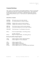
Constant Definitions
These values are various definitions used throughout RoboBrain. Some are just constants
used with functions and some are actual memory mapped registers. Only the LED and
IN_SW registers need to be accessed directly. All the other registers have interface
functions already defined to easy use. These functions are explained throughout this
manual.
Motor/Device Constants
MOTORA
MOTORB
- DC motor A, top row on motor connector
- DC motor B, bottom row on motor connector
STEPPERA
STEPPERB
- Stepper motor A, top row on motor connector
- Stepper motor B, bottom row on motor connector
SERVOA
SERVOB
- Servo motor A, top row on servo motor connector
- Servo motor B, bottom row on servo motor connector
SPEAKER
- Piezo buzzer port. Use with pwm() or freq_out()
SEG_L
-Left seven-segment display. Use with seg_driver()
SEG_R
(no longer supported)
-Right seven-segment display. Use with seg_driver()
Device ports (memory-mapped registers)
LCDI
LCDD
-Address mapped to LCD for sending instructions
-Address mapped to LCD for sending data
LED
IN_SW
SEGA
EXTRA
-Address mapped to LEDs
-Address mapped to switch block
-Address mapped to left seven-segment
-Address mapped extra port. Used with IR sensors and motors
RoboBrain©
University of California, Santa Cruz
44
RoboBrain User Manual
Rev. 4
2004 Robobrain 1.0 Software by Noah Wilson & Adam Bean
2005 Robobrain 2.1 Software by Noah Wilson
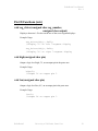
Time Functions (time.h)
#include “time.h”
void pause(int delay)
Pauses the processor for the amount of time in ms given by the delay parameter.
For example, the following code pauses the microcontroller for several different
time values:
pause(1000);
pause(250);
pause(1);
//pause for 1 second
//pause for ! of a second
//pause for 1ms
Serial I/O library (sio.h)
#include “sio.h”
void initUART()
Must call this function in order to receive user input and output from
HyperTerminal. This function will initialize the UART to be polled driven, and
must be called first, before using any other of the Serial IO functions. To enable
the UART, call the function:
initUART();
void putchar(char c)
Print a character to the UART. This is used in conjunction with HyperTerminal to
debug or print out results in your program. For example, to print the character ‘A’
to the HyperTerminal, call the following function:
putchar(‘A’);
RoboBrain©
University of California, Santa Cruz
45
RoboBrain User Manual
Rev. 4
char getchar(void)
Receive a character from the UART. This is used in conjunction with
HyperTerminal to receive user input to interface program application. To use this
function, simply assign the function to a variable of type “char” and it will wait
for user input. For example:
char temp;
temp = getchar();
This will assign the variable temp to the first character that the user types in at the
HyperTerminal session.
char *getstr(void)
This is similar to getchar(), but it will read an entire string up to 16 characters in
length. The string will be terminated when the user enters the return key. To
receive a string from the user in HyperTerminal, simple assign the function to a
variable of type “char *”. For example:
char *temp;
temp = getstr();
This will assign the variable temp to a string that is read from user input in a
HyperTerminal session.
int getint(void)
Receive an integer from the UART. This is used in conjunction with
HyperTerminal to receive user input to interface program application. To use this
function, simply assign the function to a variable of type “int” and it will wait for
user input. For example:
int temp;
temp = getint();
This will assign the variable temp to the first character that the user types in at the
HyperTerminal session.
RoboBrain©
University of California, Santa Cruz
46
RoboBrain User Manual
Rev. 4
void cls(void)
Clear the screen of a HyperTerminal session. Simply call the function “cls(); “
anywhere in your program code, and it will clear the HyperTerminal screen.
Motor Functions (motor.h)
#include “motor.h”
void step(int motor, int direction)
Move a stepper motor forward or backwards one step. Use either STEPPERA or
STEPPERB for motor parameter.
Example Usage:
step(STEPPERA, 1);
//move STEPPERA forward one step
step(STEPPERB, -1);
//move STEPPERB back one step
void enable_motors()
Enables the motor driver chips.
void disable_motors()
Disables the motor driver chips to save power on RoboBrain.
RoboBrain©
University of California, Santa Cruz
47
RoboBrain User Manual
Rev. 4
void motor_speed (int motor, int speed)
Run a DC motor connected to the motor connector until another call to
motor_speed() stops it using 0 for the speed argument. MOTORA and MOTORB
are possible values for the motor. In the direction argument, possible values are
any integer from -100 to 100.
A call to enable_motors() is required before the motors will function.
Example Usage:
enable_motors();
//run MOTORA forward
motor_speed(MOTORA, 100);
//run MOTORB backward
motor_speed (MOTORB, -100);
//stop the motors
motor_speed (MOTORB, 0);
motor_speed (MOTORB, 0);
unsigned char readIR(unsigned char channel)
Turn ON the on-board IR channel that is connected to the EXTRA interface
PORT and return the value for that IR sensor on the A/D. The parameter
“channel” specifies which of the 2 channels to turn ON. This function will return
an 8-bit value corresponding to the intensity of the IR light entering the IR
receiver. To read the first channel of the IR LED, call:
Value = readIR(0x01);
// Read A/D value of IR emitter
// closest to the 7-segment
// and save to ‘value’
RoboBrain©
University of California, Santa Cruz
48
RoboBrain User Manual
Rev. 4
LCD Functions (lcd.h)
#include “lcd.h”
void initLCD(void)
Initialize the LCD in order to interface with RoboBrain. This function call only
needs to be run once, and requires that the timer is initialized before hand. To
initialize the LCD, simply call:
initLCD();
This function must be called before the charLCD() function can be used properly.
void charLCD(unsigned char character)
Prints a character to the LCD Device. For example, the following code prints the
letters ‘R’ and ‘B’ to the LCD screen:
charLCD(‘R’);
charLCD(‘B’);
RoboBrain©
University of California, Santa Cruz
49
RoboBrain User Manual
Rev. 4
Pin I/O Functions (io.h)
#include “io.h”
void seg_driver(unsigned char seg_number,
unsigned char output)
Display a character 1-F in hex on the one of the seven-segment displays.
Example Usage:
seg_driver(SEG_L, 0x03);
//display “3” on left 7-segment display
seg_driver(SEG_R, 0x0C);
//display “C” on right 7-segment display
void high(unsigned char pin)
Output a logic level high, 5V, on an output pin in the proto area.
Example Usage:
high(5);
//output 5V on output pin 5
void low(unsigned char pin)
Output a logic level low, 0V, on an output pin in the proto area.
Example Usage:
low(3);
//output 0V on output pin 3
RoboBrain©
University of California, Santa Cruz
50
RoboBrain User Manual
Rev. 4
void toggle(unsigned char pin)
Output the opposite of the current voltage on an output pin in the proto area. For
example, if currently outputting a logic high, will output a logic low, and visa
versa.
Example Usage:
toggle(4);
//output the opposite of the current
//voltage on output pin 4
void setPin(unsigned char pin, unsigned char value)
Output the logic level given by the value parameter on an output pin in the proto
area.
Possible values for value parameter:
1 – output logic level high(5V)
0 – output logic level low (0V)
Example Usage:
setPin(2, 0);
//output 0V on output pin 2
unsigned char readPin(unsigned char pin)
Read the state of an input pin in the proto area. Will return either 1, for logic
level high (5V), or 0, for logic level low (0V).
Example Usage:
unsigned char pin;
Pin = readPin(3);
//Pin variable will now contain the
//value of input pin 3
RoboBrain©
University of California, Santa Cruz
51
RoboBrain User Manual
Rev. 4
void pwm(int channel, int duty, int num_cycles)
Outputs a pulse-width modulated signal on one of the 5 PWM channels of
RoboBrain. The possible channels are the following:
MOTORB
SERVOA
MOTORA
SERVOB
SPEAKER
The duty parameter determines the duty cycle of the output wave. This is given
as a number from 0 to 255; 0 being a solid low signal, 255 being a solid high
signal. The formula for a given duty cycle in terms of a percent high vs. percent
low is given as follows:
Dutycycle% * 255 = duty
The num_cycles parameter determines the number of full periods that the signal is
output. A num_cycles value of 0 will output the signal infinitely until the
stop_pwm() function is called.
Example usage:
pwm(MOTORA, 128, 5);
This will output a 50% duty cycle on the MOTORA port for 5 periods.
void stop_pwm(int channel)
Stops output of pwm signal on the specified channel. Values of channel taken
from pwm() function definition above.
Usage:
stop_pwm(MOTORA);
This would stop output on a MOTORA port.
RoboBrain©
University of California, Santa Cruz
52
RoboBrain User Manual
Rev. 4
void freq_out(int pin, int frequency, int duration)
Output a square-wave of a specified frequency for a specified duration in ms.
Can be used to output sound through the piezo speaker on the RoboBrain board.
Example Usage:
freq_out(5, 5000, 50);
//output 5kHz signal for 50ms on
//output pin 5
freq_out(SPEAKER, 7000, 500);
//output 7kHz signal for " second on
//piezo speaker
void puls_out(int pin, int pulse_width)
Inverts an output pin for a specified length of time, given in microseconds.
Pins available for function:
SERVOA
SERVOB
1 – 8 (output pins)
Example Usage:
puls_out(1, 30);
//output a pulse on output pin 1 for 30us
puls_out(SERVOA, 25);
//output a pulse on SERVOA port
void intensityLED(unsigned char value)
Measure the range of the past in parameter. For example, the function:
intensityLED(0x7f);
This function will light up only half of the on-board LEDs. See the function
definition (in io.c) to modify the scale in which these lights are mapped to.
RoboBrain©
University of California, Santa Cruz
53
RoboBrain User Manual
Rev. 4
void initINT(unsigned char interrupt_number)
Initialize the external interrupt buttons for interrupts 1 and 0.
initINT(0);
initINT(1);
//initialize interrupt 0
//initialize interrupt 1
Once the interrupt has been initialized, all that is left is to define a function that is
called when the interrupt occurs (button is pressed). See the interrupt section of
the manual for information on how to do this.
I2C Functions (i2c.h)
#include “i2c.h”
void initI2C(void)
This function enables the I2C protocol to be interrupt driven. It is currently
function to interface with the I2C Analog-to-Digital Converter, but can be
modified to support other ICs as well. To enable the I2C bus, call the function:
initI2C();
This function must be called before any of the following functions can be used
properly.
void writeDAC(unsigned char voltage)
Emit a voltage output corresponding to the 8-bit register value past into the
functions parameter field. Will take in any value from 0 to 255. To find out what
voltage will output with what value passed to the function, use this formula:
(desired voltage / 5V) * 255 = value to pass to writeDAC()
For example:
writeDAC(128);
writeDAC(255);
writeDAC(0);
RoboBrain©
// Voltage Out on I2C header is 2.5V
// Voltage Out on I2C header is 5V
// Voltage Out on I2C header is 0V
University of California, Santa Cruz
54
RoboBrain User Manual
Rev. 4
unsigned char readADC(unsigned char channel)
Read the digitized analog output from the I2C Analog-to-Digital Converter. The
parameter “channel” specifies which of the 4 pins should be sampled. The
channels are numbered from 0 to 3 for the four channels. See the ADC section
for more details on the location of these pins. For example:
unsigned char temp;
temp = readADC(0x01);
// This function call will read the voltage value that
//is on PIN1 of the Analog-to-Digital header.
unsigned char readIR(unsigned char channel, unsigned char mode)
Return the digital outputted signal from the I2C Analog-to-Digital Converter. The
parameter “channel” (0, 1, 2, or 3) determines which channel from the Analog-toDigital header should be sampled from. The mode parameter allows you to
specify whether to take the sample as single ended, or a differential output,
meaning the difference between the first two analog inputs. For example:
unsigned char;
char = readIR(1, 0);
// Samples analog input 1,
// in single ended mode.
Assuming that the Infrared LED has been jumpered on channel 1 of the ADC
header, it will return the 8-bit sampled voltage value.
If the mode is set to one, and channel is set to one, it will take the differential
values of Analog Input 1 and Analog Input 2. If the channel is set to two, then the
differential values of Analog Input 3 and Analog Input 4 will be sampled.
RoboBrain©
University of California, Santa Cruz
55
RoboBrain User Manual
Rev. 4
Hardware changes in second version:
• Reduced original I/O system down to single-chip solution described in Verilog on
Altera CPLD.
Resulting Features:
o In-system programmability for desired I/O changes.
o Fewer IC’s for easier assembly.
o Almost fully software compatible across versions.
•
•
•
•
•
•
•
•
•
•
•
•
•
•
•
Reduced two digit 7-segment display down to one digit. SEG_L and SEG_R
addresses now point to the same single 7 segment display.
Removed all system jumpers and replaced with dip switches.
Added Main Power Switch.
Removed RF capabilities/connections.
Removed Latched Proto I/O Ports.
o Data-Bus and control still accessible for Proto-Board use through LCD
interface
o Use LCD port to address any addons to that interface
Motor Drivers now socketed and placed closer to their respective motors. Also
room for external Staver V7 heat sink for thermal relief above the chips
Changed Board Dimensions to 3.5in x 4.5in.
Digital System 9v AC compatible. 7-12V DC recommended.
Added 16 diodes to motor output to prevent damaging inductive kick from
motors.
Added 2 I2C Analog to Digital converters for up to 6 additional line detection
sensors with amplification
Added two additional Intensity emitters and sensors for left and right IR vision.
Accessible on channels 2 and 3 on Analog to Digital Converter 0.
Removed sensor-enable jumpers.
Two control signals now enable emitter output
o
One controls line detector emitters
o
One controls radial emitters (left, front left, front right, right)
Removed Analog output ports access headers.
Piezo speaker now driven by CPU and not CMOS inverter.
RoboBrain©
University of California, Santa Cruz
56
RoboBrain User Manual
Rev. 4
Conclusion
We hope that this kit has been helpful and a learning experience to the user. We tried to
cover some of the most basic and important aspects of engineering and simplified it. If
we receive enough feedback, there is a possibility for a better revision, depending on
what the majority of the users would like to see out of it. The CPLD added gives future
uses more development and customization options.
Contacts
Bazeghi, Cyrus
Bean, Adam
Petersen, S.C.
Thompson, William
Wilson, Noah
Cormier, Ryan
Binnewies, Andreas
RoboBrain©
[email protected]
[email protected]
[email protected]
[email protected]
[email protected]
[email protected]
[email protected]
University of California, Santa Cruz
57
RoboBrain User Manual
Rev. 4
Appendix A – Robots for COSMOS
The Robobrain robotics platform was originally designed for use with the COSMOS
summer programs at UCSC. This program works with high school students and prepares
them for their college academic career. The following information will outline what is
needed to create Robobrain for your own class as well as cover some of the subtle issues
we encountered while teaching the class.
Parts
The following part list will help you construct your RoboBrain for COSMOS. The parts
are categorized and some part reference numbers and/or surface mount sizes have also
been provided. The approximate cost for one Robobrain using this part list is $180.
ICs
1
1
1
1
2
3
3
Linear Regulator 7805
Philips 8051 Microcontroller
Altera CPLD
MAX232I/SO Serial Transceiver
SN754410 Half H-Bridge Driver
PHILIPS PCF8591 8bit A/D converter
LMC6484 Quad Op Amp SOIC
DIGIKEY:LM7805CT-ND/TO-220
PHILIPS:P89C668
ALTERA:EPM7128S
DIGIKEY:296-6940-5-ND
DIGIKEY:296-9911-5-ND
DIGIKEY:568-1088-2-ND
DIGIKEY:LMC6484AIMX
Capacitors
2
7
22
1
1
27pF
10uF
.1uF
1uF
47uF 25V
Surface Mount 0805
Surface Mount 0805
Surface Mount 0805
Surface Mount 0805
Axial
470ohm
4.7Kohm
10Kohm
330ohm
100ohm
270ohm
100Kohm
47Kohm R_NETWORK_BUS_9
470ohm R_NETWORK_BUS_9
470ohm R_NETWORK_ISO_8
Surface Mount 0805
Surface Mount 0805
Surface Mount 0805
Surface Mount 0805
Surface Mount 0805
Surface Mount 0805
Surface Mount 0805
DIGIKEY:4310R-1-473-ND
DIGIKEY:4310R-1-471-ND
DIGIKEY:767-163-R470-ND
Resistors
3
8
10
10
1
6
6
3
1
1
RoboBrain©
University of California, Santa Cruz
58
RoboBrain User Manual
Rev. 4
Diodes
9
18
1
1
Green LED Surface Mount 0805
1N4001 DIODE Axial
1N5401 DIODE 3Amp Axial
1-Digit 7-Segment-Display
DIGIKEY:SML-LXT0805GW-TR
DIGIKEY:1N4001
DIGIKEY:1N5401
DIGIKEY:160-1575-5-ND
Tact Pushbutton SPST
SW DIP-8
SW DIP-4
POWER SW DPST
DIGIKEY:CT2098MS-ND
DIGIKEY:CT2094MS-ND
DIGIKEY:P8102S-ND
Switches
3
1
1
1
Sensors and Emitters
4
4
6
IR emitter
IR sensor
Line detection Sensor/Transducer
DIGIKEY:QED523-ND
DIGIKEY:QSD733-ND
DIGIKEY:QRB1114-ND
Jacks and Sockets
1
1
1
1
1
PJ-102BH DC POWER JACK
3 Input Terminal Block
FEMALE D-SUB9 Serial Jack
PLCC 84pin Thru Hole TO Socket
PLCC 44pin Thru Hole TO Socket
JAMECO:104951
DIGIKEY:ED80027-ND
DIGIKEY:ED80024-ND
Headers and Other Parts
1
2
1
1
1
2
1
4
40pin Male DIP Header
20pin Male SIP Header
20pin Female SIP Header
PIEZO SPEAKER
Regulator Heatsink
Motor Driver Heat sink
20Mhz Crystal
FF Spacers
JAMECO:207950
Staver V7 Heatsink
DIGIKEY:CTX062-ND
Motors and Misc. Parts
2
2
1
1
1
2
DC Motor
Roller Blade Wheels
!” Plexiglass for Chassis
3/4” Plexiglass for Chassis
Sheet Metal for Chassis
Custom Aluminum Hubs
RoboBrain©
Jameco: 155862
University of California, Santa Cruz
59
RoboBrain User Manual
Rev. 4
Characterizing the IR Sensors
Every one of the IR sensors used here behaves slight different from one another. For a
given distance, two sensors may give different values. As a result, characterization of the
sensors is necessary to get consistent distance measurements. We devised a simple
calibration procedure for the students to perform to calibrate their sensors and then fit the
sensor data to a 3rd order polynomial for sensor data to distance conversion during run
time. The procedure involved placing each sensor of the robot at some distance and then
placing a white surface, in this case we used some white card stock, at 1cm intervals from
the sensor and recording the 8-bit sensor value from the analog to digital converter at
each interval. This data can be put into an array in MATLAB and the polyfit() function
can be used to generate a polynomial function the closely matches the sensor data. This
resulting polynomial can then be used the source code on the Robobrain to get consistent
measurements from different sensors.
RoboBrain©
University of California, Santa Cruz
60