1
Service Manual
Preface
pHOx Service Manual
Stat Profile® pHOx® Service Manual
Part Number and Ordering Information
The Stat Profile® pHOx® Service Manual (PN 24301) can be ordered from Nova Biomedical
Order Services. Write or call:
Nova Biomedical
200 Prospect Street
Waltham, MA 02454-9141
U.S.A.
Tel:
1-800-458-5813
FAX: (781) 893-6998 (in the U.S.A.) or
(781) 899-0417 (outside the U.S.A.)
Technical Assistance (USA)
For technical assistance, call Nova Biomedical Technical Services at:
Tel:
1-800-545-NOVA or
(781) 894-0800
FAX: (781) 894-0585
Trademarks
Stat Profile® is a registered trademark of Nova Biomedical.
pHOx® is a registered trademark of Nova Biomedical.
Copyright
Printed in the U.S.A. Copyright 2005, Nova Biomedical, Waltham, MA 02454.
i
Preface
ii
pHOx Service Manual
Stat Profile pHOx Service Manual
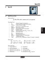
Contents
1.0 Introduction . . . . . . . . . . . . . . . . . . . . . . . . . . . . . . 1-1
1.1
1.2
1.3
The Stat Profile pHOx Analyzer ............................................................................1-1
1.1.1 Environmental ............................................................................................1-1
1.1.2 Energy consumption ..................................................................................1-1
1.1.3 Physical Dimensions ..................................................................................1-1
1.1.4 Regulatory Compliance .............................................................................1-1
1.1.5 Location - Stable stationary surface. .........................................................1-2
1.1.6 Operational.................................................................................................1-2
1.1.7 General .......................................................................................................1-2
Cautions and Hazards ............................................................................................1-3
Required tools .......................................................................................................1-4
2.0 Product Description . . . . . . . . . . . . . . . . . . . . . . . . . 2-1
2.1
2.2
Mechanical Assemblies..........................................................................................2-1
2.1.1 Pump ..........................................................................................................2-2
2.1.2 Sampler Assembly ....................................................................................2-2
2.1.3 Rotary Valve Assembly .............................................................................2-2
2.1.4 Sensor Module Assembly .........................................................................2-3
Electronic Assemblies. ...........................................................................................2-3
2.2.1 Power Entry Module .................................................................................2-3
2.2.2 Power Supply ............................................................................................2-3
2.2.3 Digital Control Board ...............................................................................2-4
2.2.4 Analog Board .............................................................................................2-6
2.2.5 SO2 Control Board.....................................................................................2-6
2.2.6 Electrode Interface Boards .........................................................................2-7
2.2.7 Door Assembly Electronics........................................................................2-7
PN 24301 Rev. B 2005/11
TOC-1
Table of Contents
3.0 Replacement Procedures . . . . . . . . . . . . . . . . . . . . 3-1
3.1
3.2
3.3
3.4
3.5
3.6
3.7
3.8
3.9
3.10
3.11
3.12
3.13
3.14
3.15
3.16
3.17
3.18
3.19
Cover Removal.......................................................................................................3-1
Tubing Harness .....................................................................................................3-2
Power Supply Removal ..........................................................................................3-4
Sampler Assembly .................................................................................................3-5
Rotary Valve Assembly ........................................................................................3-10
Valve Assembly ....................................................................................................3-11
Rotary Valve Motor ..............................................................................................3-12
Pump Assembly ...................................................................................................3-13
Digital Control Board ..........................................................................................3-14
Analog Board ......................................................................................................3-15
Printer Assembly .................................................................................................3-16
Sensor Module Light Source ...............................................................................3-17
Door Removal /Reinstallation Procedure ...........................................................3-18
Display Assembly ................................................................................................3-20
Distribution board ...............................................................................................3-21
Keypad Assembly ...............................................................................................3-21
Sensor Module Assembly ....................................................................................3-22
Electrode Interface Boards ...................................................................................3-23
Pinch Valve Assemblies .......................................................................................3-24
4.0 Troubleshooting Information . . . . . . . . . . . . . . . . . . 1-1
4.1
4.2
4.3
TOC-2
Service Screens ......................................................................................................1-3
4.1.1 System Test Screen ....................................................................................1-4
4.1.1.1 Operator Flow Test .........................................................................1-4
4.1.1.2 Service Flow test ............................................................................1-5
4.1.2 Analog Input Screen ..................................................................................1-6
4.1.3 Sensor Subsystem .....................................................................................1-7
4.1.4 Printer Menu ..............................................................................................1-8
4.1.5 Communication Tests .................................................................................1-9
Flow Problems .....................................................................................................1-10
4.2.1 Isolating a Plug in the W/R to Waste Tubing ...........................................1-11
4.2.2 Isolating a flow problem in the Sampler/Sensor module .........................1-11
4.2.3 Isolating a flow problem between the Fluid Pack and the Fluid Fountain1-12
Status Codes .......................................................................................................4-13
4.3.1 Analyte Troubleshooting ( Series code 1-6 and Digit codes 1-4) ............4-18
4.3.2 Single Channel Failures ......................................................................4-20
4.3.3 Temperature Problems .............................................................................4-21
4.3.4 Air Detector (ADT ) Problems ................................................................4-21
Operator Flow Test ...............................................................................................4-26
Sensor Module Back Flush Procedure .................................................................4-27
PN 24301 Rev. B 2005/11
Stat Profile pHOx Service Manual
A
Appendix . . . . . . . . . . . . . . . . . . . . . . . . . . . . . . . . A-1
A.1
A.2
A.3
A.4
A.5
A.6
S
Quick Reference Guide .........................................................................................A-1
General Maintenance/QC......................................................................................A-8
A.2.1 Other Analyzer Maintenance ..................................................................A-12
pHOx Electrode/Standards..................................................................................A-13
Electronics and Mechanicals Overview ..............................................................A-13
Shutdown Procedure ...........................................................................................A-14
Start Up Procedure ..............................................................................................A-14
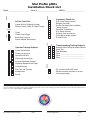
Installation Check List ........................................................................................A-15
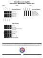
Preventive Maintenance Check List....................................................................A-17
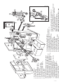
Explosion Parts List ............................................................................................A-19
Schematics . . . . . . . . . . . . . . . . . . . . . . . . . . . . . . . S-1
#10-1087A
S-2
#10-1071B
#10-1072B
#10-1073B
#10-1074B
#10-1075A
#10-1076B
#10-1077B
#10-1078B
#10-1079B
#10-1080B
#10-1081B
#10-1082B
#10-1083B
#10-1084B
#10-1085B
#10-1086A
Wiring Doucument ...................................................................................... S-1
Wireing Charts ............................................................................................. S-2
24292-01 pHOx Digital Board Processor and Memory ............................. S-3
24292-02 pHOx Digital Board Comm. Printer, Display Touch Memory ... S-4
24292-03 pHOx Digital Board Motor & Valve Drivers .............................. S-5
24292
pHOx Digital Board Assembly Drawing .................................... S-6
21642
pHOx SO2 Board ........................................................................ S-7
24727
pHOx Distribition Board ............................................................ S-8
24291
Analog Board - Cortex Assembly Drawing .............................. S-9
24292-01 New Gen. Sensor Board ........................................................... S-10
24292-02 New Gen. Sensor Board ........................................................... S-11
24292-03 New Gen. Sensor Board ........................................................... S-12
24292-04 New Gen. Sensor Board ........................................................... S-13
23897
Pump Assembly ........................................................................ S-14
23899
Sampler Assembly .................................................................... S-15
23898
Rotary Valve Drive Assembly ................................................... S-16
24614
Printer Interface IF3001 Seiko ................................................. S-17
24720
Power Supply Universal input .................................................. S-18
PN 24301 Rev. B 2005/11
TOC-3
Table of Contents
TOC-4
PN 24301 Rev. B 2005/11
1 Introduction
This manual contains information and procedures used in servicing the Stat Profile
pHOx Analyzer. The intent is to supplement the information provided in the Stat
Profile pHOx Instructions for Use Manual (PN 37865) and the Stat Profile pHOx
Advanced User Applications Manual (PN 35235). This manual does not supersede
any current performance specification claims, expendable maintenance procedures, or warranty criteria as outlined in the reference manual.
1.1
The Stat Profile pHOx Analyzer
1.1.1 Environmental
Ambient Temperature:
Ambient Humidity:
15° - 32° C ( 59° - 86° F)
0% - 95% Non-condensing
1.1.2 Energy consumption
Air Conditioning Load:
Peak 44 BTU/Hour
Power Consumption:
~130 watts peak
Power requirements:
100-120; 230-240 VAC, 50/60 Hz
•
2 Amp Time Delay (SB 2A or T2A) at 100-120VAC line
•
1 Amp Time Delay (T1A) at 220-240 VAC line
1.1.3 Physical Dimensions
Weight:
Dimensions:
8.1 Kg (18 lbs)
38 cm high (15 in) x 31 cm (12 in) wide x 38 cm (15 in) depth
1.1.4 Regulatory Compliance
The analyzer is tested and acceptable to attach the CSA, GS (Europe), JIS
(Japan), and CE (self declaration) safety marks, and compliant with EN1010-1,
EN55011, and IEC 801-2.
1-1
1. Intro.
1.0 Introduction
pHOx Service Manual
1.1.5 Location - Stable stationary surface.
•
•
•
8 cm ( 3 in) clearance to a wall or adjacent instrumentation
Not intended for use on vibrating (helicopter, etc.) surface
Placement on a cart is acceptable if the cart is stationary during operation.
1.1.6 Operational
The analyzer is designed to be on at all times. It may be turned off without special
procedure or consideration for up to 1 hour with no detrimental effect on the sensors or fluidics.
The tubing should be flushed and the pump tubing relaxed prior to extended shutdown periods.
Any shutdown period will require a 2-point calibration and verification by control
material upon restarting operation.
1.1.7 General
The analyzer utilizes an Intel 386EX processor, PCMCIA ROM programming.
There are three RS-232 connectors, utilizing ASTM protocol, and one Bar Code
reader connection.
The display is a backlit liquid crystal (LCD) with type that is CCFT backlit with 320
x 240 pixel resolution.
The internal optional printer is a 20 column thermal international font /166 dot
graphics printer with ~5 cm (2 in) wide paper.
NOTE:
1-2
The circuit boards use fine pitch surface mount technology. Field repair of these circuit boards is not possible.
DO NOT attempt to repair any components on the board.
1 Introduction
1. Intro.
1.2
Cautions and Hazards
There are NO user serviceable assemblies inside the analyzer. Only a trained,
authorized service representative should remove the cover of this analyzer.
WARNING: Removal of the top cover allows access to power supply
voltages. Care should be taken to avoid electrical shock.
Remove the power cord prior to accessing any internal
assemblies.
WARNING: Blood samples and blood products are potential sources of hepatitis
and other infectious agents. Handle all blood products and flow path
components (waste-line, capillary adapter, probe, sensor module, etc.)
with care. Gloves and protective clothing are recommended.
NOTE:
This International Caution Label appears on the rear of
the pHOx Analyzer and means refer to the manual.
It is the responsibility of the service representative to decontaminate any assembly
or analyzer being returned to Nova for repair or warranty claim.
Decontamination of external surface of the flow path may be accomplished by a
wipe down with cleaning agent or 10% bleach solution.
The Internal surfaces of the flow path and tubing should always be considered
contaminated. Prior to removal from the analyzer, ensure that the flow path and
tubing are emptied.
WARNING: Internal surfaces may have sharp edges. Care should be
taken to avoid cuts and scrapes when accessing internal
assemblies.
Used tubing, biosensors, electrodes, reagents, controls, etc. may be disposed by
normal laboratory waste procedures.
1-3
pHOx Service Manual
1.3
Required tools
The analyzer is designed to require no unique or special tools. Flow path cleaning
wires/kits are provided in the accessory kit. Avoid metal wires or other material that
may scratch the internal surfaces of the flow path.
•
Digital Volt Meter (2 decimal accuracy)
•
Phillips® screwdriver (crosshead) preferably one with 15 cm (6 in) shank
•
Spring clip expander wrench or comparable means of releasing tension of
retention clips
•
Pliers - needle nose or small snub nose
1-4
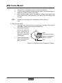
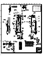
2 Product Description
2.0 Product Description
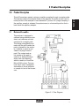
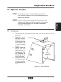
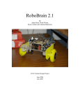
2.1
Mechanical Assemblies
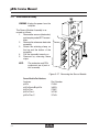
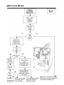
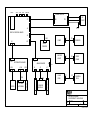
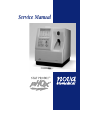
The analyzer is designed to
calibrate using calibration standards and reference solution
contained in a reagent pack.
The tubing automatically connects with the pHOx when the
pack is placed into the analyzer. Likewise, a space is provided for a plug-in control
pack. The content and serial number of the pack is
coded in a “Dallas Semiconductor Add-Only Memory,”
which is read by a One-Wire
MicroLAN® system. The analyzer has 4 major mechanical
assemblies to move calibrator
or sample in front of the biosensors.
Figure 2-1 Flow Diagram
2-1
2. Descrip.
The pHOx analyzer accepts syringe or capillary samples through a sample probe.
The operator selects the sample mode via the keypad. The probe moves from its
home position in the analyzer to an extended 45° position for syringe sampling. If
the capillary sample is selected, the probe moves to a horizontal position that is
back inside the capillary adapter.
pHOx Service Manual
2.1.1 Pump
The analyzer uses one pump (PN 21492) for 2 functions. The pump aspirates
either sample or calibration standards from the sample probe, through the sensor
module/reference electrode, through a solenoid actuated pinch valve, and delivers
to the waste bottle of the reagent pack.
The second function of the pump is to aspirate the reference solution from the
reagent pack and deliver it to the reference electrode through a solenoid actuated
pinch valve.
2.1.2 Sampler Assembly
The sampler assembly (PN 21504) utilizes a probe that rotates to 1 of 3 possible
positions. The HOME position is vertical with the tip of the probe seated against a
"Fluid Fountain” assembly that is the common port of the rotary valve.
The syringe position is the probe tip extended out in front of the analyzer at approximately a 45° angle. The capillary position is horizontal, but the tip is totally
inside the capillary adapter. This allows the capillary to be used without a separate
adapter. (This position is also used to change the capillary adapter.)
The capillary adapter is pushed onto the end of the sampler. Extending the probe
outward from the capillary position ensures that the probe will be seated inside
of the adapter. The sampler will exert enough force to push the adapter off of the
sampler if it is not aligned correctly.
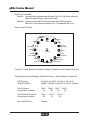
2.1.3 Rotary Valve Assembly
The rotary valve assembly (PN 22215) has one common port connected to the
sampler’s fluid fountain. Each calibration standard and quality control standard
is connected to a port on the rotary valve. The rotor positions a central port connecting one of the fluids to the outlet port. The outlet port is connected to the Fluid
Fountain by the S-Line. Starting the pump aspirates the selected fluid into the flow
path.
The rotary valve's manifold also has positions that allow air to enter the S-line. Refer to the replacement procedures for actual positions.
2-2
2 Product Description
2.1.4 Sensor Module Assembly
2.2
Electronic Assemblies.
2.2.1 Power Entry Module
The power entry module (PN 22818) provides the interconnect to wall power. The
fuses are found in the accessory kit for the operating voltage (120 VAC PN 22814,
236 VAC PN 22817). The power entry module connects to the power supply
through TB1.
2.2.2 Power Supply
The power supply (PN 21602) provides all of the power requirements for the analyzer. The analog and logic voltage used in the pHOx are + 5VDC. The stepper
motors are driven by +24 VDC. This module has no repairable parts inside. The
power supply connects to the digital control board by TB2.
2-3
2. Descrip.
The Sensor Module Assembly contains the measuring sensors, flow cell, and
preheater. The measuring sensors clip into place upon insertion. The sensors have
contacts instead of cabled connectors. When mounted, the sensor module forces
the sensor contacts to align with the matching contacts on the left/right interconnect boards. The module also contains the light sources and detector for the
SO2% channel and 2 air detectors.
Please refer to the drawing section and Appendix A for individual part numbers.
pHOx Service Manual
2.2.3 Digital Control Board
There are 2 Digital Control Boards: all units with monochromatic display use
PN 24292, and all units with a color display use PN 40797. The main controlling
board of the analyzer uses an Intel 386X processor with the following integrated
peripheral functions:
•
Clock and Power Management unit
•
Watchdog Timer Circuit
•
Asynchronous Serial I/O unit
•
Synchronous Serial I/O unit
•
Parallel I/O unit
•
Refresh control unit
•
JTAG- Complaint Test Logic Unit
The digital control board provides one 72 pin socket for a 4 MB SIMM module of
RAM. This volatile memory stores the calibration, slope, and millivolt data.
Major circuit identification:
U25 is the main clock generator; it is crystal controlled 14.318 MHz and a phaselocked-loop frequency generator. This generates a 50.11 MHz CPU clock,
14.318 MHz for VGA video timing, and 1.84 MHz for Baud rate generation.
U35 is the real time clock containing a battery which will retain the date/time,
setup options, daily QC (up to 144 points), Error log (last 96 errors FIFO),
and sample counter data. The battery has an expected 10 year life.
U37 PEROM stores the monthly (256 data points) and YTD QC data, QC setup
information, and recognition of the QC fluid pack presence.
PCMCIA contains the operational program and boot program. This card must be
in place for the unit to function.
U43 is the video control chip. U26 controls the printer output and the I/O ports
Comm 1 and Comm 2. U36 is the DUART that controls the Comm 3 I/O
port.
U16 provides the serial interface for the (RMS) interface and fluid pack memories.
The mechanical devices are controlled by U18. The Keypad and “home” sensors
for the rotary valve and sampler are ported through U18. The stepper motors are 4
phase stepper motors. U18 controls the speed and direction each phase is powered. U3 and U4 provide the power for each winding of the pump motor. U5 and U6
power each phase winding of the sampler motor. U7 and U8 power each phase of
the rotary valve motor.
U18 also provides the logic signal to operate the other mechanical devices. Typically, the devices are connected to either 12 VDC or 24 VDC and the logic provides
a ground path through a transistor. The waste valve solenoid (12 VDC) grounds
through Q3, the reference solenoid (12 VDC) through Q4, the sensor module lamp
(24 VDC) through Q6, and the preheater (24 VDC) through Q2. The 24 VDC valve
boost circuit is on the board but not used on the pHOx analyzer.
2-4
2 Product Description
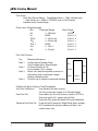
Power is received from the power supply through the J7 connector on the digital
control board.
Power Supply Connector TB2
5
Ground
6
Ground
7
+5 VDC
8
+5 VDC
Digital Board Connector J7
Pin 1
2
3
Ground +24 VDC. +5 VDC
4
+5 VDC
5
6
7
8
Ground +12 VDC. Ground -12 VDC
Sensing
Wire Color
Black
Violet
White
Red
Black
Orange
Green
Yellow
Individual circuits are protected from an over current condition by the use of Positive Temperature Coefficient Resistors (PTC). These resistors act as a direct short
if the current is below a set current. If the current increases, the resistors heat up
and open, similar to a fuse. When the device cools off, the connection is remade,
allowing the circuit to function. The following lists these devices:
R22 - Solenoid common boost circuit (not used on pHOx)
R24 - Heater power circuit
R29 - Printer motor power
R43 - Print Head heater power
R44 - +24 VDC
R45 - +5 VDC
R71 - Bar Code Reader (+5 VDC out)
R249 - Distribution board power (This board is mounted in the door.)
The LED indicators on this board are mostly unused. All will light at power up and
then go off. The exception is D8 - 100 Hz Clock. D9 - 386 Strobe will appear to be
always on. D7 is your program fail indicator and will come on with a software reset.
Connectors:
J1 Bar Code Reader
J2 COMM 1
J3 COMM 2
J4 COMM 3
J5 JTAG
J6 PCMCIA
J7 Power Supply
J8 Mechanical Assemblies
J9 Printer Connector
J10 Analog Board J11 - Display/Keypad (Motors/heater/lamp/solenoids and door)
2-5
2. Descrip.
1
2
3
4
+12 VDC. -12 VDC +24 VDC. Ground
pHOx Service Manual
2.2.4 Analog Board
There are 2 Analog Boards: pHOx, pHOx Basic, BiopHOx use PN 24291 and
pHOx Plus, pHOx Plus L, and pHOx Plus C use PN 33390. U34 is the microprocessor that controls the signal acquisition and digital conversion. The signals are
connected through several connectors.
•
Left Sensor Interface board J6 - PCO2, pH, Reference, Air Detector (ADT) 4
•
Right Sensor Interface board J7 - PO2, Na+
•
Sensor module J4 -SO2% detector, Preheater temp, ADT2, ADT3/Hct
•
Mechanical assemblies J3 - ADT1
Barometric pressure sensor U9 is on the analog board. The Analog to Digital Conversion (ADC) is performed by U31. The signals are multiplexed through U26 and U32.
Preheater temperature control circuits are on the analog board. +24 VDC are
ported through J3 to the SO2%/sensor module board (J4). The heater power wiring is protected on the digital control board by a PTC Resistor; the Heater has an
in line thermostat (50°C) in the sensor module. The thermistor has 18.25 Kohms
resistance at 37°C. The signal will change at a rate of 22.5 millivolts/0.1°C.
There are 4 ADTs in the system. ADT1 holds the sample probe (40 uL setting).
ADT2 at the inlet to the sensor module (70 uL). ADT3 is at the input to the sensors
and is also used for the Hct. ADT4 is in the reference electrode housing.
Logic and analog power is supplied to the analog board from the digital control
board. Logic voltage (+5 VDC) enters J1 pin 14. The analog +5 VDC enter J1 pin 3
and -5 VDC J1 pin 4. The analog board provides power to the SO2 board through
+5 VDC J4 pin 5 and -5 VDC J4 pin 6.
2.2.5 SO2 Control Board
SO2 Control Board is an integral part of the Sensor module. It controls the 2 LED
light sources that glow at 880 nM and 660 nM, respectively.
2-6
2 Product Description
2.2.6 Electrode Interface Boards
The electrode interface boards are found only on pHOx
and pHOx Basic.
The Electrode Interface Boards have 2 part numbers: PN 20641 (Left) and
PN 20674 (Right). The electrodes are wireless. The electrodes have point contacts
which engage the Interface board contacts when inserted into the sensor module.
The left interface board, connecting to the analog board through J6, has 3 sets of
contacts: one set for the reference electrode/ADT4, one set for Na+, and one set
for PCO2 sensors. The reference electrode/ADT4 has 3 individual point contacts
while the Na+ and PCO2 have 2 individual point contacts.
The right interface board has 2 sets of contacts: one for the pH and one for the
PO2 sensors; each consisting of 2 individual point contacts. This board is connected through J7 to the analog board.
2.2.7 Door Assembly Electronics
The door assembly electronics include the Display Assembly, the Distribution
Board, and the Keypad Assembly. The digital control board sends/receives signals
to the door via the flat cable J104 on the distribution board.
NOTE:
See Section 3.13 for part numbers that are model specific.
The keypad, which is glued onto the door, connects to the distribution board via
J102 and has a ground cable clamped to the conductive surface on the inside of
the door. The Analyze key also connects to the distribution board through this connector.
The distribution board also provides the signal path to the display assembly and
power to the display back lighting lamp. The display is a liquid crystal, graphics display. It has a 320 x 240 dot matrix (1/4 VGA) yielding a 122 x 92 mm (4.99 x 1.33
inch) viewing area. This translates to a 40 x 20 character display using a standard
character set. The display is backlit by cold cathode fluorescent tube (CCFT).
An 8 ohm voice coil loudspeaker is mounted on the distribution board, producing
all associated sounds.
2-7
2. Descrip.
NOTE:
pHOx Service Manual
2-8
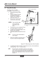
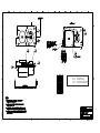
3 Replacement Procedures
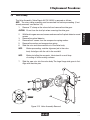
3.0 Replacement Procedures
CAUTION: Assemblies may have loose hardware mounting. Ensure no loose hardware is left in the unit before restoring
power to the analyzer.
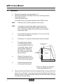
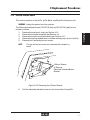
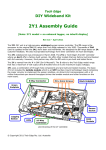
Cover Removal
1.
2.
3.
4.
Turn the unit OFF, disconnect the line cord, and have the back of the unit
facing you.
R e m o ve t h e 4
Screws (2)
rear-panel-cornermounting screws.
Lift the printer cover
and remove the
2 cover mounting
screws.
Slightly spread the
bottom sides and
slide the cover toward the back. This
Mount
will disengage the
Screws (4)
internal clips at the
front of the cover.
Lift the cover off the
unit.Take care not to
damage any cables
or wiring during removal.
Figure 3-1 Cover Removal
3-1
DWG #10-1029A
3.1
3. Replace.
WARNING: Removal of the analyzer cover will allow access to line
voltage wiring. Power should be turned off and the power
cord disconnected before any assembly replacement
procedure is performed.
pHOx Service Manual
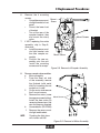
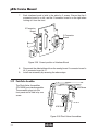
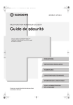
Tubing Harness
1.
2.
Remove the analyzer cover per Section 3.1.
Remove the digital control shield. There are 4 mounting screws:
One at the top front
One at the bottom front
Two at the bottom rear (above and below the PCMCIA card)
NOTE:
Take care not to lose the spacers on the screws.
NOTE:
It is optional to remove the digital control board and
mount plate when accessing the reference and waste
line. To remove the digital control board and mount plate,
follow these steps:
a.
Disconnect the electrical connectors (J7, J8, J9, and J10)
from the top of the board.
b.
Disconnect J11 connector at the bottom front of the board.
c.
The digital control board
and mount plate come off
as one assembly. There are
3 mounting screws: two on
the rear panel and one at
the top front on the printer
box. (Take care not to damage the board.)
d.
Slightly lift the board and
mount plate upward and out
from the side of the analyzer.
e.
Remove the ground strap
on the back of the board.
Digital Control Board
Mount Plate
Mount
Screws (3)
(4)
Digital Control
Board
DWG #10-1030A
3.2
Figure 3-2 Removing the Digital
Control Board/Mount Plate
3.
3-2
Remove the R and W-lines from their front panel fitting. (Looking at the front
panel, R is on the left.) If you have not removed the digital control board, it
may be easier to remove the panel fitting nut on the front panel and move
the fitting to the new tubing.
3 Replacement Procedures
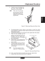
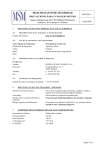
4.
Carefully remove the tubing from
the rotary valve including the
center port to fluid fountain.
Take care not to damage
the valve ports. Push the
tubing end off the port to
reduce the risk of damaging the valve.
3. Replace.
G
DW
0
0-1
#1
A
40
NOTE:
Figure 3-3 Removing Tubing from Rotary Valve
6.
7.
8.
9.
NOTE:
The tubing bracket is held in place on each end by a screw. Two screws
hold the bracket in alignment; access them from the bottom of the analyzer.
Remove both screws.
Lift the bracket and tubing set, removing it from the sampler side of the analyzer.
Slide the new assembly into the
analyzer and reconnect the W and
Front Panel W and R Fittings
R-tubing to the front panel ports.
WR
Ensure that they go to the correct
ports and brackets.
Reinstall the 2 mount screws at the
bottom of the analyzer and the 2 end
mount screws.
Place the reagent tubing and S-line
W
onto their ports on the rotary valve.
R
Take care that the metal ports are
not damaged.
DWG #10-1039A
5.
The A line connects at the
lower left (7 O’clock position).
Figure 3-4 Reconnect W and R-lines
10. If the control board and mount plate were removed, replace them.
11. Reinstall the cover and restore the unit to operation.
3-3
pHOx Service Manual
3.3
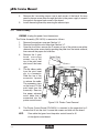
Power Supply Removal
The Power Supply (PN 24720) is removed as follows:
WARNING: Unplug the Analyzer before proceeding.
1.
2.
3.
NOTE:
4.
Remove the analyzer cover per Section 3.1.
Disconnect the power harness connectors: P1 and P3 (top of the power
supply assembly).
Remove the 4 power supply mounting screws from the rear analyzer panel.
Support the power supply before removing the mounting
screw.
Carefully lower the supply. Rotate it to access the line input module wiring
(TB1) on the bottom of the power supply.
P3
P1
Use Center Holes
to Mount
Rear
Panel
Power Supply
Mount Screws
(4)
DWG #10-1038B
Power Supply
Power Plug
On/Off Switch
Figure 3-5 Power Supply Removal
5.
6.
3-4
Disconnect TB1 and remove the power supply.
Position the new power supply with the lower side toward the analyzer. Plug
in TB1.
3 Replacement Procedures
NOTE:
NOTE:
NOTE:
9.
The holes closest to the
middle of the supply bracket
are the ones used to mount
the supply.
Brown
Connect P1 and P3.
The wires leave the top of
P1. The white wire of P3
goes to the digital display
board P7.
Black
Green &
Yellow
TB1
Guide
Power
Supply
Reinstall the unit cover and power
cord.
Figure 3-6 Power Supply Position
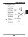
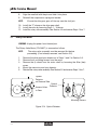
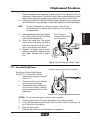
3.4
Sampler Assembly
The Sampler Assembly (PN 23899) is removed as follows:
1. Remove the probe and the air detector.
a. From the Menu screen, select Flowpath/Probe Maintenance and press
Enter.
b. Press Move Probe (soft key). Open the door.
c. Remove the capillary adapter from the front of the probe by gently pulling it off.
d. Disconnect the air detector's sample line from the sensor module.
e. Disconnect the 2-prong cable.
f.
Push the air detector down and pull the air detector with the probe out
of the sampler assembly.
WARNING: Unplug the Analyzer before proceeding.
2.
3.
NOTE:
Remove the analyzer cover per Section 3.1
Cut the tie wraps on the rear of this assembly.
Care should be taken to avoid cutting wires.
3-5
3. Replace.
8.
Position the new power supply to align with the mounting holes in the back
panel.
DWG #10-1037A
7.
TB1 male end has 3 wires. The female end has 5 sockets.
The Green/Yellow wire is closest to you.
pHOx Service Manual
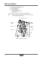
4.
5.
STOP:
Disconnect the following connectors:
J5 Motor cable connector
J10 Home detector
P6 door switch cable
Sensor module light cable
Ground wire
Remove the S-Line from the fluid fountain assembly.
There are washers and nuts that are NOT captive. Do not
lose any hardware into the unit.
Flow Cell Light Source
Mount
Screw
Mount
Screws
Ground
Power
Supply
S-Line
J5, J10
DWG #10-1032B
CN3
Figure 3-7 Sampler Assembly
3-6
3 Replacement Procedures
6.
DWG #10-1034B
NOTE:
Remove sampler subassemblies.
a. Motor assembly
1. From the Gear set side
of the assembly, remove
the flywheel (solid metal
disk) by loosening the set
screws on its side.
2. On the motor side remove
the 2 mount screws.
3. Remove the motor (some
Mount Screws
tie wraps may need cutting).
Install the new motor by
reversing these steps. Use
new tie wraps as required.
b. Home detector (PN 21504)
1. Remove the sensor module light and bracket.
Touching the light glass
will shorten use life.
DWG #10-1035A
8.
Figure 3-9 Removal of Motor Assembly
3-7
3. Replace.
7.
Remove the 4 mounting
screws.
Mount
•
One at the sensor modScrew
ule light bracket to front
panel
•
One at the lower front
of bracket
•
Two at the rear of the
sampler bracket, they
Mount Screws
also mount the rotary
valve.
If NOT replacing the entire
assembly, skip to Step 8,
otherwise:
a. Install the sensor module light bracket onto
the new sampler asMount Screw
sembly.
b. Position the new assembly onto the unit.
Install the mounting
screws and tie wraps.
Figure 3-8 Removal of Sampler Assembly
pHOx Service Manual
2.
3.
4.
NOTE:
Remove the 2 mounting screws from the home detector.
Install the new detector by reversing these steps. Use new tie wraps as
required to prevent fouling of the wires.
After restoring power, ensure the capillary adapter seals against the
Fluid fountain in the Home position. If not, adjust the Home flag on the
top gear.
Ensure the home flag enters the detector without obstruction.
DWG #10-1045A
C. Gear Set (PN 22634)
1. The gears are held in position by compression springs. These can be
removed by spreading the open end and lifting.
2. Remove the old gears
noting the position
and orientation of
Gear
each gear. The noise
Compression Spring
damper is behind the
middle gear.
Spread Compression
3. After installing the new
Spring to loosen
gears, ensure that the
Post
gears run freely.
Figure 3-10 Removal of the Compression Spring
3-8
3 Replacement Procedures
DWG #10-1041A
Figure 3-11 Fluid Fountain Assembly
3-9
3. Replace.
D. Fluid Fountain Assembly (PN 24620)
1. Rotate the gears so the capillary adapter lifts off the fluid fountain assembly.
2 . Remove the S-Line
from the bottom of the
spike assembly.
3. Loosen the mounting nut (under the
Capillary
sampler bracket).
Adapter
4. Slide the fluid fountain assembly off the
sampler.
5. Move the washer and
mount nut to the new
assembly.
Fluid
6. Slide the new assemFountain
bly onto the sampler.
7. Rotate the sampler
Sampler
gears until the capillary presses down on
the fluid fountain
Washer
assembly.
Nut
NOTE:
The fluid fountain
should be centered
and should move
S-Line
downward between
0.06 to 0.08 inches
(1.5 to 2.0 cm).
pHOx Service Manual
Rotary Valve Assembly
The Rotary Valve Assembly
(PN 23898) is removed as follows.
1. Remove the cover per Section 3.1.
2. Optional: Perform this step
to enhance accessibility.
Remove the sampler assembly per Section 3.4.
3. Remove the 7 tubes and SLine from the rotary valve.
CAUTION: Care should be taken
not to scratch the
metal tubes of the
valve.
4.
5.
6.
NOTE:
Mount
Screws
(2)
Disconnect the motor connector J2 and
the optical detector connector J9.
Loosen the 2 mounting screws at the
bottom of the assembly.
Slide the assembly toward the front and
lift.
The front of the valve bracket is
hook shaped.
Slide the assembly toward the back of
the unit to clear the sampler bracket.
G
DW
#1
0-1
0
04
A
7.
Flow Cell Light Source
DWG #10-1036B
3.5
Figure 3-12 Removing Rotary Valve Assembly
8.
NOTE:
3-10
If replacing the entire assembly, install the new rotary valve assembly by
following Steps 1 thru 7 in reverse order.
Ensure the red, nonmetallic washers for the sampler
mount screws stay in place during the remounting process. If only repairing the rotary valve assembly, refer to
Section 3.6. If repairing the rotary valve motor, refer to
Section 3.7.
3 Replacement Procedures
Valve Assembly
The Valve Assembly (Valve Repair Kit PN 24626) is removed as follows:
NOTE: The rotary valve assembly must be removed first before proceeding. (If not
already removed, see Section 3.5.)
1. Remove “C” clamp on the valve shaft and remove the drive gear.
CAUTION: Do not lose the shaft pin when removing the drive gear.
With the drive gear removed, access and remove the 2 optical-detector mount
screws.
Remove the optical detector.
Remove the 4 screws from the compression spring washer.
Remove the washer and compression spring.
Slide the rotor and tube manifold out of the valve body.
3.
4.
5.
6.
NOTE:
Before proceeding, note the alignment pin in the valve
body that aligns with the slot in the manifold.
NOTE:
Before installing the new parts, lubricate with a small drop
of sealing oil on the mating surfaces.
7.
Slide the new rotor into the valve body. The large flange side goes in first.
Align with the drive pins.
B
C
A
D
S
J9
DWG #10-1033A
E
G
F
Figure 3-13 Valve Assembly Removal
3-11
3. Replace.
2.
DWG #10-1019A
3.6
pHOx Service Manual
8.
9.
NOTE:
Align the manifold with the pin and slide it into place.
Reinstall the compression spring and washer
Ensure the drive gear goes all the way over the shaft pin.
10. Install the “C” clamp on the drive gear shaft.
11. Install the valve by reversing Steps 1 - 10 above.
12. Install the rotary valve assembly. See Section 3.5 and reverse Steps 1 thru 7.
3.7
Rotary Valve Motor
WARNING: Unplug the power from the analyzer.
The Rotary Valve Motor (PN 24627) is removed as follows:
NOTE:
1.
2.
3.
4.
5.
The rotary valve assembly must be removed first before
proceeding. (If not already removed, see Section 3.5.)
Remove the drive gear/opto detector as in Steps 1 and 2 in Section 3.6.
Remove the 4 mounting screws from the motor.
Remove the fly wheel from the motor shaft byFlow
loosening
the Source
Allen (hex)
Cell Light
screw.
Mount the new motor and opto detector.
Reinstall the rotary valve assembly. See Section 3.5 and reverse Steps 1 thru 7.
Access Holes
in Gear
Optical
Detector
DWG #10-1026B
DWG #10-1027A
Optical
Detector
on Reverse Side
Mounting Screws
Figure 3-14 Optical Detector
3-12
3 Replacement Procedures
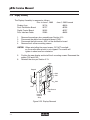
Pump Assembly
The Pump Assembly (PN 23897) is removed as follows:
1. Remove the analyzer cover per Section 3.1.
2. Remove the digital control board shield. There are 4 mounting screws:
One at the top front
One at the bottom front
Two at the bottom rear (above and below the PCMCIA card)
3.
Take care not to lose the spacers on the screws.
Remove the digital control board and mount plate.
a. Disconnect the electric connectors (J7, J8, J9, and J10) from the top
of the board.
b. Disconnect J11 connector at the bottom front of the board.
c. The digital control board and mount plate come off as one assembly.There
are 4 mounting
plate screws: two
WR
on the rear panel
and two under the
printer box.
NOTE:
Take care not
to damage the
board.
d.
Slightly lift the
mount plate and
the board upward
and out the side of
the analyzer.
Pump
Assembly
W
R
Figure 3-15 Pump Assembly
4.
5.
6.
7.
Disconnect the motor connector J1.
Remove the pump cap (on the front side of the pHOx) by pulling it off.
Remove the 4 corner mounting screws then remove the pump.
Install the new pump by reversing the above steps.
3-13
3. Replace.
NOTE:
DWG #10-1048A
3.8
pHOx Service Manual
3.9
Digital Control Board
WARNING: Unplug the power from the analyzer.
The Digital Control Board is removed as follows:
1.
2.
Units manufactured after June 1, 2005, use PN 40797;
Units manufactured through June 1, 2005, use PN 24292.
Remove the analyzer cover
per Section 3.1.
Remove the digital control
board shield. There are 4
mounting screws:
-One at the top front,
-One at the bottom front
-Two at the bottom rear
(above and below the PCMCIA
card)
NOTE:
The shield is not present on units manufactured after June 1,
2005.
Mount
Screws
(4)
Shield
DWG #10-1047A
NOTE:
Figure 3-16 Digital Board Removal
3.
4.
Take care not to lose the spacers on the screws.
At the top of the board,
disconnect the electrical connectors:
• J 7 - Power Supply
• J 8 - Mechanical devices harness
• J 9 - Printer (Pull side
tabs outward to release
the cable.)
• J10 - Analog Board
At the front lower corner
disconnect J11 – Display/ PCMCIA
keyboard (pull side tabs Release
outward to release cable). Button
Mount Screws
Digital Control
Board
Figure 3-17 Install PCPMIC Card
3-14
Shield
Stand
Offs
DWG #10-1046B
NOTE:
3 Replacement Procedures
5.
6.
7.
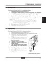
3.10 Analog Board
The Analog Board is removed as follows:
1.
2.
3.
Basic/BiopHOx, pHOx/pHOx use PN 24291; pHOx Plus,
Plus L,Plus C use PN 33390; all jumpers will be in the
3 to 4 position. To access the top/rear mounting screw,
use a long shank (15 cm or 6 inch) Phillips® head (cross
head) screwdriver.
Remove the analyzer cover per
Section 3.1.
Disconnect the sampler ground
strap.
Disconnect the cable connectors
from the Analog board Sensor
Interface board connectors:
J6 - 3 sensor board
J7 - 2 sensor board
J4 - Sensor module/SO2 cable
J3 - RMS/Fluid Deck (Pull side
tabs outward to release cable.)
J1 - Digital control board
J4
J6
J7
J3
Analog
Board
Mount
Screws
J1
DWG #10-1049B
NOTE:
Figure 3-18 Analog Board Removal
3-15
3. Replace.
8.
9.
10.
11.
12.
13.
14.
15.
Remove the PCMCIA card (PN 22805) Push the button below the PCMCIA
card (bottom rear corner) to release the card.
Remove the 2 mounting screws and 2 shield standoffs:
One screw is at the top rear corner
One screw is between J8 and J9 connectors
One shield standoff is at the top front and the other is at the bottom front
Remove the 8 COM connectors screw standoffs at the rear of the pHOx by
unscrewing 2 standoffs from each COM port.
Remove the board.
Position the new board on the mount plate.
Install the 2 mounting screws and the 2 shield standoffs.
Install the 8 COM connector screw standoffs.
Reinstall the PCMCIA card into its slot.
Reconnect all the cable connectors.
Reinstall the digital board shield (4 screws).
Reinstall the cover and restore the analyzer to operation.
pHOx Service Manual
4.
5.
Remove the 3 mounting screws: one in each corner of the board. You may
need to place a screw driver through the holes in the power supply to access
the screw in the upper back corner of the board.
Install the analog board by reversing the above steps.
3.11 Printer Assembly
WARNING: Unplug the power from the analyzer.
DWG #10-1050A
The Printer Assembly (PN 24615) is removed as follows:
1. Remove the analyzer cover per Section 3.1.
2. Remove the digital control board per Section 3.7.
3. Open the front door; remove the 2 screws on top of the printer cover plate;
remove the printer cover plate by pushing the plate from the inside outward;
then remove the paper and roller bar.
4. Remove the 3 print
Printer Cover
head mounting
screws: two at the
top of the print head
2 Screws
and one at the lower
right.
5. The flat ribbon cable
from the print head
sits in a connector.
Slide the top of the
connector upward
to release the cable.
The connector stays
on the board. Tilt the
print head from the
assembly. Remove
the paper advance
motor cable that is
connected into the
printer control board.
Figure 3-19 Printer Cover Removal
6.
NOTE:
3-16
The Printer Control Board (PN 24614) is mounted to the paper box by 2
screws that fit into the slots. Loosen the screws and slide out the board.
Save cable that goes from the printer control board to J9
of the digital control board.
3 Replacement Procedures
7.
8.
NOTE:
When installing the new assembly, install the printer control board first. Do not
tighten the 2 slotted screws. This allows access when connecting the print head
cable. Attach the paper advance motor cable to the printer control board.
Install the print head. Connect the flat ribbon cable. The easiest way to plug in the
print head cable is using one finger on each side. Tighten the 3 print head screws.
The print head cable is clamped in place. Lift up on the
white connector to release the flat cable for easy removal
or replacement.
9.
Use 2 Fingers to
Connect Printer Cable
to Printer Board
DWG #1
0-1051A
3. Replace.
After connecting the print head, tighten
the printer control board mounting
screws inside the paper box.
10. Attach the cable from the printer
control board (key faces up, blue or
black wire faces towards the front of
unit) to the digital control board.
11. Reinstall the digital control board,
shield, printer cover, analyzer cover,
and paper. Restore unit to operation.
Figure 3-20 Attaching the Printer Cable
3.12 Sensor Module Light Source
Flowcell Light Source Mount Screws
DWG #10-1052A
The Sensor Module Light Source
(PN 24717) is removed as follows:
1. Remove the analyzer cover per
Section 3.1.
2. Remove the 2 screws of the light
source mounting bracket.
3. The light bulb is removed by pushing it into the socket, rotating it
counterclockwise a 1/4 turn, then
releasing it.
Figure 3-21 Removing Mounting Screws
CAUTION: Do not touch the glass surface of the new light.
4.
5.
6.
7.
Place the glass end of the new light bulb into the tubing provided.
Insert the light bulb into the socket. Push it in and rotate it clockwise a 1/4
turn. Then pull off the tubing.
Reinstall the bracket.
Reinstall the covers and restore the unit to operation.
3-17
pHOx Service Manual
Push and rotate 1/4 turn counterclockwise to
unscrew light.
DWG #10-1053B
Push plastic tube
over lamp . Do not
touch glass of new light bulb.
Push and rotate 1/4 turn
to clockwise to install new
bulb into socket
Figure 3-22 Tubing for Light
3.13 Door Removal /Reinstallation Procedure
CAUTION: Until free of the
hinge and cables,
support the door
to prevent stress
to other cables/
assemblies.
105
4B
Use a pencil to
3 Mounting
trace the position
Screws
of the hinge onto
the door mounting
plate.
10-
STOP:
Turn the unit OFF and
disconnect the line
cord.
DW
G#
1.
Figure 3-23 Door Removal
3-18
3 Replacement Procedures
NOTE:
4.
Remove the 3 hinge screws from the door plate.
Remove the 5 plate-mounting screws: one in each corner, plus one at right
side.
Care should be
taken not to strip
the threads.
Keypad
Display Shield
5 Plate
Mounting
Screws
Door
Distribution
Board
Figure 3-24 Door Removal Continued
5.
Reinstall the Door by reversing the above steps. Use the pencil marks made
on the door plate to realign the door to the hinge. Ensure the door opens
and closes easily and aligns with the chassis.
Analyzer
pHOx
pHOx Basic/ BiopHOx
pHOx Plus
pHOx Plus L
pHOx Plus C
PN of Door
21493
33102
30817
34082
35350
3-19
3. Replace.
Remove the plate
and disconnect the
flat cable (J101). This
frees the door. Place it
face down on a protective surface to prevent
scratching.
DWG #101055B
2.
3.
pHOx Service Manual
3.14 Display Assembly
The Display Assembly is removed as follows:
Prior to June 1, 2005
Display Assy.
24716
Door Distribution Board
24727
Digital Control Board
24292
Door Interface Cable
21983
1.
2.
3.
4.
June 1, 2005 forward
40910
40795
40797
40495
Remove the analyzer door assembly per Section 3.13.
Disconnect the cable from the display board (CN2).
Disconnect the light source, J103, on the distribution board.
Remove the 4 corner mounting screws.
CAUTION: When reinstalling the mount screws, DO NOT overtighten. Assure the door plastic is not stripped. The screws will
tighten in about one turn clockwise.
5.
6.
Position the new display and install the 4 mounting screws. Reconnect the
cables CN2 and J103.
Reinstall the door per Section 3.13.
CN2
Keypad
J104
DWG #10-1065A
J101
J102
J102
Light Source
J103
Keypad Clip
Ground
Strip
Figure 3-25 Display Removal
3-20
3 Replacement Procedures
3.15 Distribution board
CAUTION: When reinstalling the mount screws, DO NOT overtighten. Assure the door plastic is not stripped. The screws will
tighten in about one turn clockwise.
5.
6.
Reconnect cables J104, J103, J102, and J101.
Reinstall the door per Section 3.13.
The Keypad Assembly (PN 24625) is removed as follows:
1. Remove the analyzer door per Section 3.13.
2. Disconnect the cable connector J102 from the distribution board.
3. Remove the clip holding the keypad
ground strip to the door. Save this for
reuse.
4. The Keypad is held by adhesive to the
front panel. Peel the old assembly from
the front of the door.
5. Clean the surface of any debris.
6. Remove the protective backing from
the new keypad.
7. Slide the cable/ground strap through
the hole in the door. Align and press
new keypad in place.
8. Fold the ground strap over the ledge
and reinstall the clip.
Keypad Clip
9. Plug in J102 and reinstall the door per
Ground
Section 3.13.
Strip
DWG #10-1056A
3.16 Keypad Assembly
Figure 3-26 Keypad Removal
3-21
3. Replace.
The Distribution Board (PN 24727) is removed as follows:
1. Remove the analyzer door per section 3.13.
2. Disconnect the cable connectors J104 and J103 coming from the display
board, J101 coming from the digital control board (should already be disconnected), and J102 coming from the Keypad. (Refer to Figure 3-25.)
3. Remove the 4 corner mounting screws.
4. Position the new distribution board (J101 will be on the hinge side of the
door) and remount.
pHOx Service Manual
3.17 Sensor Module Assembly
WARNING: Unplug the power from the
analyzer.
NOTE:
The preheater and SO2
component are all part of
this assembly.
R
DWG #10-1059A
The Sensor Module Assembly is removed as follows:
1. Remove the sensors (electrodes)
and sample probe/ADT1 assemblies.
2. Remove the reference electrode
assembly.
3. Rotate the retaining clamp on
the top and the bottom of the
assembly.
4. Pull the assembly toward you.
5. Remount by reversing these
steps.
W
Figure 3-27 Removing the Sensor Module
Sensor Module Part Numbers
Analyzer
pHOx
pHOx Basic/BiopHOx
pHOx Plus
pHOx Plus L
pHOx Plus C
3-22
Part Number
21494
34653
27807
34738
37343
3 Replacement Procedures
3.18 Electrode Interface Boards
This section pertains to the pHOx, pHOx Basic, and BiopHOx Analyzers only.
WARNING: Unplug the power from the analyzer.
NOTE:
3 Mount Screws
to Remove
Electrode Interface Board
Bracket
DW
G#
10-1
057
A
The top left corner screw was removed with sampler removal.
Figure 3-28 Removing the 3 Mount Screws
6.
Pull the electrode interface board out thru the inside of the pHOx.
3-23
3. Replace.
The Electrode Interface Boards (PN 24719 {left} and PN 24718 {right}) are removed as follows:
1. Remove the analyzer's cover per Section 3.13.
2. Remove the sampler assembly per Section 3.4.
3. Remove the sensor module assembly per Section 3.17.
4. Remove the spring loaded sensor module retaining clips (front of pHOx).
5. Remove the 3 remaining mount screws.
pHOx Service Manual
7.
Each interface board is held to the plate by 2 screws. Ensure that the 3
connector board is on left, and the 2 connector board is on the right when
looking at it from the front.
3 Connector
Board
DWG #10-1058A
2 Connector
Board
Figure 3-29 Correct position of Interface Board
8.
9.
Disconnect the affected board from the analog board: 3 connector board to
J6, 2 connector board to J7.
Install new assembly by reversing the above steps.
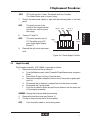
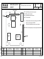
3.19 Pinch Valve Assemblies
0-1059A
#10 Screw
DWG #1
The Pinch Valve Assemblies
(PN 16928) are interchangeable.
The assembly plugs into the
front panel and is held in by one
screw.
#10 Screw
Figure 3-30 Pinch Valve Assemblies
3-24
4 Troubleshooting
4.0 Troubleshooting Information
This section contains suggestions for individual error codes, cycle information to
help identify the cause of an error condition, and hints on basic troubleshooting.
1.
Troubleshooting is recognizing the variance from normal operation. The
calibration cycle can be used as the sequence of events where the cycle
response and results are known.
Fluid Function
all 4 ADTs, Hct, PCO2, Na+, K+, iCa, Cl-, Gluc, Lact
PCO2
pH, Na+, K+, Cl-, Gluc, Lact, (iCa on pHOx +L)
all ADTs, pH, Hct, (iCa on pHOx+C)
4. Trouble.
Start cycle
Std. A
Std. B
Std. C
Std. D
PO2 uses Room Air (A-air position of the rotary valve).
SO2/Hb utilizes external calibrators. (These are model specific.)
2.
Sensor Methodology
ISE sensors - Na+, K+, iCa, Cl-, pH, and PCO2
ISE requiring a reference signal - Na+, K+, iCa, Cl-, pH
ISE with its own internal reference - PCO2
Reflected Impedance - Air Detectors 1,2,4, 3/Hct
Amperometric - PO2, Glucose, Lactate
Optical Reflectance - SO2%
3.
Calibrator Functions other than calibration.
PO2 Std. B is used to flush the system.
PO2 is monitored on all fluids in the Calibrator pack. If the PO2 millivolt reading varies from that of room air, a 72 Delta mV error is generated indicating
a contaminated calibrator pack.
Std. D has surfactant and is used to clean the flowpath between pump cycles.
4-1
pHOx Service Manual
4.
Dependencies (Refer to the quick reference guide in the appendix.)
Hct Calibrated Na+ required
NOTE: The pHOx Na+ is a 30 day expendable electrode.
SO2%
Hb
PCO2
Calibrated Hct and PO2 required
Calibrated Hct and SO2% required
Calibrated pH required
Calculated values will not be reported if a needed test is suppressed.
P50 is reported only if PO2 is between 30 mmHg (4 kPa) and 75 mmHg (10 kPa).
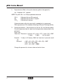
5.
Password protection - One password for Set Up, QC, and Service menus.
Should the password be lost, enter the following number when asked for the
password.
Date Code
“Back-door” Password = (((month x 31) + day) x 137) + (year x 16)) + 5987
2 digits
2 digits
last two digits
Example: If today is 02 January 2003 the “back-door” password would
be:
Password
= (((01 x 31) + 02) x 137) + (03 x 16)) + 5987
= (33 x 137) + 48 + 5987
= 4521 + 48 + 5987 = 10556
Change the password to a known value and write it down.
4-2
4 Troubleshooting
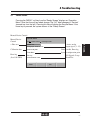
4.1
Service Screens
Pressing the “MENU” soft key from the “Ready Screen” displays an “Operation
Menu.” Note that the soft key labels change. The “QC” label changes to “Service”
(second key from the left). Pressing this key will display the Service Menu. If the
home key is pressed, the system returns to the “Ready Screen.”
Manual Device Control
Service Menu
Use
to select. Press
to change / enter.
System T est
Active analog
input signal (1 - 25)
Analog Input - Real Time mV
Calibration data
Sensor Subsystem
Printer enable, Error log,
System configuration print
Printer Menu
Error log
(Last 100 FIFO)
I/O Signals / Loop
Back Test
Error Log
Comm unications Tests
Home
Exit
4-3
4. Trouble.
Manual Device
Control
+ Flow test
pHOx Service Manual
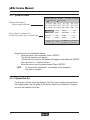
4.1.1 System Test Screen
System Test Rev: 123.456
Measured Parameters/
Current signal (millivolt)
Use to select. Press to select / enter.
pH: +047.43 LED1: +314.3
Na: +147.4
AD3: +314.3
PCO2: -082.12 LED2: +314.3
AD4: +314.3
PO 2: -051.20
Device Names (column 1&3) /
Current state of the device (column 2&4)
11-23-96 10:54 am
AD1: +314.3
HCT: +007.43 AD2: +314.3
Rot. Valve:
STD A
Sampler:
Pump:
CTRL 1
SO 2% LEDs:
Waste valve:
Ref. valve:
Home
Open
Closed
Exit
Temp:
Home
On
Air Osc:
On
X level:
Hct
Operator
Exit
Flow Test
37.0
Service
Flow Test
Test
Flow
Manual Control of a mechanical device:
•
Move the cursor over the device /Press “ENTER.”
•
The Option selections will appear.
(If there are only 2 options, the device will toggle its state when the “ENTER”
key is pressed, i.e., solenoid valves.)
•
Move the cursor over the option wanted /Press “ENTER.”
NOTE:
To successfully move fluids, a knowledge of the complete
flow path is required.
4.1.1.1 Operator Flow Test
Pressing the soft key under the Operator Flow Test turns on the pump and raises
the sample probe. Use the guide in this Section titled Flow Problems in Conjunction with the Operator Flow Test.
4-4
4 Troubleshooting
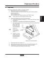
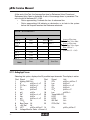
4.1.1.2 Service Flow test
4-5
4. Trouble.
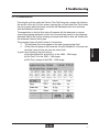
Pressing the soft key under the Service Flow Test brings up a screen that displays
the results of this test. On this screen, pressing the soft key under Run Test causes
the unit to pump each fluid twice: once with the Reference valve shut and once
with the Reference valve Open.
The expectation is that the flow time will increase with the decrease in vacuum
caused by pumping reference solution into the waste line junction in the reference
electrode. Ideally the 2 pump windings are equal and the flow time will double with
the reference solenoid valve open.
The pumping times will yield 2 pieces of information:
1. The individual flow times appear at the end of pumping that fluid.
2. All the fluids will pump at the same rate. Usually Standard D is the one standard that varies in flow rate from the other fluids.
A good rule of thumb for the flow rates is
pHOx Basic/BiopHOx and pHOx is in the 1000 – 1200 range.
pHOx Plus/C is in the 1200 – 1300 range.
pHOx Plus L pumps in the 1300 – 1400 range.
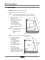
pHOx Service Manual
At the end of the Test, the Average flow time for Reference Valve Closed and
Reference Valve Open is displayed. A ratio of the average times is presented. The
ratio should fall between 0.5 – 0.65.
•
Ratios approaching 1 indicate the loss of reference flow.
•
Ratios approaching 0.0 indicate an obstruction or air leak in the system
before the flowpath reaches the Reference electrode.
FLOW TEST RESULTS
CAL A
1180
CAL B
2010
CAL C
CAL D
0.58
QC 1
QC 2
1190
AVG FLOW 1
1195
AVG FLOW 2
1190
1170
RATIO
Average Flow time
Reference Valve Shut
Average Flow time
Reference Valve Open
Flow 1/Flow 2
(nominal 0.5 – 0.65)
1195
1193
QC 3
1195
Print
EXIT
Run Test
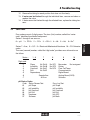
4.1.2 Analog Input Screen
Selecting this option, displays the 25 possible input channels. The display is active.
Chnl Signal
Unit
Chnl
Signal
Unit
PO2
pHOx+, pHOx+ C
1
Analog GND ALL
15
+
2
K
pHOx+,+L,+C
15
Lac
pHOx+L
pHOx+,+L
16
Glu
pHOx+,+L,+C
3
Cl-/Ca++
3
ClpHOx+C
17
PO2
pHOx+L
++
4
Ca
pHOx+C
18
PO2
pHOx+,+C
5
pH
pHOx
18
Lac
pHOX+ L
pHOx+,+L,+C
20
Temp 0.00=37C
5
Na+
pHOx
22
LED1
ALL
6
Na+
6
pH
pHOx+,+L,+C
23
LED2
ALL
7
PCO2
All
24
ISE Ref
ALL
PCO2,Ref
ALL
8
Barr.Press. All
25
9
+5V Ref
All
13
HCT
pHOx, pHOx+C 14
PO2
pHOx, pHOx+C
10
Voltage Monitor Sums +24 and +5
4-6
4 Troubleshooting
4.1.3 Sensor Subsystem
This set of screens shows the calibration data for each analyte measured by the
pHOx. Use the “NEXT” soft key to page to the analyte of interest.
Last 2-point calibration data
Millivolts for each standard
Slope calculated
Last 1 point data
(Millivolts should be similar
to the same Standard in 2 point cal)
pH Sensor
Callibration & Analysis Data
mV
mV
STDA
+ 43.1
STDA
STDB
+ 43.1
SAMPLE
STDC
+ 43.1
CONC
STDD
+ 43.1
SLOPE
+ 43.1
+ 43.1
97.4
- 7.1
Next
Page
Exit
Print
Sample millivolts and concentration - Unknown and therefore not relevant to
troubleshooting
Useful to the clinician for any possible dilution
SO2 LED 1
SO2 sensors - Each LED has its own screen.
Displays similar data to the other
Measured parameters, plus
The “dark” (off) and “Light” (full)
Signals are shown
Callibration & Analysis Data
STD1
mV
+ 379.1
SAMPLE
STD2
+ 379.1
CONC
DARK
+ 379.1
LIGHT
+ 379.1
SLOPE
+11.4
Home
Print
Exit
AIR
+ 117.0
FLUID
THRESHOLD
AD1
+ 54.0
+ 99.0
mV
+ 379.1
Next
Page
Air Detector Subsystems
Air Detectors
Displays the millivolts for Air and
Liquid. (Air column is actually Standard D.)
Shows the AIR/Liquid threshold
(set by the analyzer) millivolt level
NOTE:
Numbers shown on this screen
are not real values.
Callibration Data
AD2
+ 117.0
+ 54.0
+ 99.0
AD3
+ 117.0
+ 54.0
+ 99.0
AD4
+ 117.0
+ 54.0
+ 99.0
Exit
Next
Page
Home
Print
4-7
4. Trouble.
Home
pHOx Service Manual
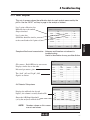
4.1.4 Printer Menu
This menu is straight forward. Move the cursor to the desired action and press
“ENTER”
Printer Menu
Use
to select. Press
to change / enter.
Enable/Disable internal printer
Printer: Enabled
Prints last errors
Print System Error Log
Print System Dump
Prints setup configuration and
millivolt data
Character Set Test
Test Print
Home
4-8
Cancel
Printout
Exit
4 Troubleshooting
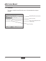
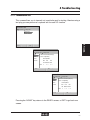
4.1.5 Communication Tests
This screen allows you to transmit out a particular port for testing. Likewise using a
test plug you can perform a Loopback test for each I/O function.
Communications Tests
Use to select. Press
to change / enter.
Loop Back Tests
Send test characters.
4. Trouble.
Home
Exit
Loopback Tests
Use
to select. Press
to change / enter.
COOX
1. Select Port and install loopback plug.
ASTM
2. Press to begin testing.
Remote
Tests Completed: 0
Bar Wand
RXD
DTR
RTS
TXD DSR DCD CTS RI
Errors
Home
0
0
0
0
0
Exit
Loopback Tests
Use
to select. Press
to change / enter.
COOX
1. Select Port and install loopback plug.
ASTM
2. Press to begin testing.
Remote
Tests Completed: 0
Bar Wand
RXD
DTR
RTS
TXD DSR DCD CTS RI
Errors
Home
0
0
0
0
0
Exit
Pressing the “HOME” key returns to the READY screen, or EXIT to go back one
screen.
4-9
pHOx Service Manual
4.2
Flow Problems
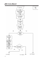
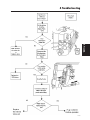
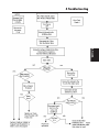
NOTE:
Each of the following troubleshooting procedures has an
associated flow diagram that may be found at the end of
this chapter.
General procedures when isolating flow problems:
NOTE:
Refer to the FLOW TEST decision tree. Do not be confused with the Flow Test Cycle that only shows the flow
times.
Unit calibrates, but the sample will not aspirate. This usually means you have an air
leak into the system. The sample, being more viscous than the aqueous standards,
causes more vacuum to be created by the roller pump. If a membrane is leaking,
this increase in vacuum will pull the aqueous fill solution from the electrode, easier
than pulling sample from the probe. Likewise, a poor connection at the interconnect tubing or between the electrode sealing washer and the sensor module will
allow air to enter easier than pulling sample up the flow path.
•
Check the connections between probe and sensor module, sensor module,
and reference electrode.
•
Check the electrodes for the loss of internal fill solution.
•
Check the flow cell window during a pump cycle, looking for bubbles entering
the flow path or pump and waste tubing.
A No flow or obstructed flow cause can be isolated by performing the FLOW TEST.
The fluidic system can be isolated into three large sections. This will limit the area
of your search. The 3 sections are Fluid Pack to Fluid Fountain, Sampler/Sensor
module, and W/R to Waste tubing. Use the SYSTEM TEST screens to control the
mechanical devices.
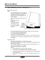
1.
2.
3.
4.
5.
NOTE:
4-10
Extend the sampler to the syringe position.
Open the waste line solenoid.
Turn on the pump and attempt to aspirate water then air from a sample
cup.
If water is aspirated from the cup, the sample probe, sensor module, external
tubing, and waste line are functioning. The problem exists between the Fluid
Fountain and Fluid Pack.
If water is NOT aspirated from the cup, remove the tubing from the outlet
port of the Reference electrode. Place it in a cup of water.
This assumes the waste solenoid has functioned and is
not pinching the tubing.
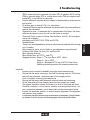
4 Troubleshooting
6.
7.
If step 5 fails to aspirate from the cup, the problem lies between the W/R
tubing and the waste bottle of the Fluid Pack.
If Step 5 does aspirate water, the problem is in the Sampler/ Sensor module.
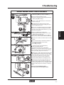
4.2.1 Isolating a Plug in the W/R to Waste Tubing
NOTE:
1.
3.
4.
5.
Disconnect the waste tubing from the reference electrode and place in a cup
of water. If water is NOT aspirated, there is a plug.
Lift the waste tubing out of the waste solenoid. If flow starts, the valve is dirty.
Clean the dirt from the waste solenoid or replace it.
If flow does NOT start, remove the waste line from the front panel connection. If water flows from this tube there is a plug in the internal waste tubing
or waste bag of the fluid pack.
Turn off the pump. Connect a syringe of water to the waste port on the front
panel. Attempt to inject water through the line to clear the plug.
If there is no flow, remove the Fluid Pack to ensure the problem is not a
poorly seated or damaged waste connection. Should the problem continue,
replace the internal tubing set.
4.2.2 Isolating a flow problem in the Sampler/Sensor module
1.
2.
3.
4.
NOTE:
You noted flow when aspirating from the waste tubing in step 2 of Section
4.2.3.
Raise the Sampler to the Syringe position. The Pump should be OFF for this test.
Connect a syringe of water to the reference electrode outlet port. Attempt to
inject the water.
If water flows freely, air is entering the system preventing aspiration.
a. Inspect each electrode to assure the internal fill solution level is not
dropping.
b. If yes, replace the electrode or membrane as required.
c. Inspect the seal between the reference electrode and sensor module
(interconnect tubing) .
If the flow path starts to empty while the syringe is still
attached, only the water below the leak will leave the flow
path out of the tip of the probe.
4-11
4. Trouble.
2.
If the reference flow is obstructed, the sample may not
stop in the sensor module due to increased vacuum. Flow
time decreases due to increased flow rate.
pHOx Service Manual
d.
5.
Inspect the sensor sealing washers for distortion or misalignment. Replace as necessary.
e. The seal between the air detector and the sample probe may be tested
by attaching the syringe to the sample probe, blocking the air detector
outlet tube. Apply pressure to the syringe and look for water leaking
out.
If water does not flow freely, there is a blockage.
a. Loosen the reference electrode. Water should pass through or the
electrode is plugged. Flushing with cleaning agent or hot water may
free the blockage.
b. If the reference is clear, reinstall it and remove the bottom electrode.
c. Apply a moderate pressure with the syringe.
d. If water does not enter the sensor module of the bottom electrode the
blockage is above it.
e. Removing one electrode at a time. Look for water entering the sensor
module. If no water enters the module as the electrode is removed, the
plug is above it.
f.
If water did enter the bottom sensor module in step C above, the plug is
in the Sample Probe/Air detector. Remove these assemblies and flush
through them or replace them.
4.2.3 Isolating a flow problem between the Fluid Pack and the Fluid Fountain
If you have successfully aspirated a sample, but the analyzer will not calibrate or
aspirate on-board controls, proceed as follows.
1. Position the sampler in the syringe position and inspect the capillary adapter
for signs of wear. Replace if necessary.
2. Lower the sampler to the Home position; connect a syringe to the reference
outlet port.
3. Remove the analyzer cover.
4. Disconnect the S-Line (center tube) from the rotary valve.
5. Inject the water and look for flow from the S-Line.
6. Look for a leak between the fluid fountain and the capillary adapter. Realign
if necessary.
7. If there is no flow from the S-Line, remove the fluid fountain/S-Line and
flush with hot water or cleaning agent, or replace the assembly.
8. If there is free flow through the S-Line, the problem is in the rotary valve,
tubing harness, or connection to the fluid pack.
9. Reconnect the S-Line and remove the fluid pack.
10. Move the rotary valve to all the possible positions, observing which ports do
not allow flow.
11. If there is no flow in ALL positions, remove the valve and clean or replace it.
4-12
4 Troubleshooting
12. Remove the tubing for each position that does not flow freely.
13. If water can be flushed through the individual lines, remove and clean or
replace the valve.
14. If water cannot be flushed through the affected lines, replace the tubing harness.
4.3
Status Codes
Error codes come in 2-digit groups. The tens (first) number, called the “series
code,” identifies the affected component.
Series 1 through 6 are sensors,
0 = pH 1 = PCO2 2 = PO2 3 = SO2 % 4 = Hb 5 = Hct 6 = Na+
Series Digit code
-1
-2
-3
-4
-5
-6
-7
1-6
7
8
Slope
No Std.A No QC1
Instability No Std.B No QC2
Overload No Std.C No QC3
Drift
No Std.D
Dependency
Sample flow
Air flow
pH Status Codes
Code Status Screen Text
01
pH Slope
02
pH Instability
03
pH Overload
04
pH Drift
96
Hardware
97
Software
9
10
Barometer
Not assigned
Printer
Flow Cell Temp
Communication
Digital Board
Analog Board (ADX)
Software
Error Log Text
pH Slope
pH Instability
pH Overload
pH Drift
pH ADC
pH Math
4-13
4. Trouble.
Series 7 = flow, 8 = Q.C. 9 = Electronic/Mechanical/Hardware 10 = CO-Oximeter
codes.
The ones (second) number, called the “digit code,” provides more information on
the failure.
pHOx Service Manual
PCO2 Status Codes
Code
11
12
13
14
15
96
97
Status Screen Text
PCO2 Slope
PCO2 Instability
PCO2 Overload
PCO2 Drift
PCO2 Dependency
Hardware
Software
PO2 Status Codes
Code
21
22
23
24
96
97
Status Screen Text
PO2 Slope
PO2 Instability
PO2 Overload
PO2 Drift
Hardware
Software
SO2 LED 1 Status Codes
Code
31
32
33
34
35
96
97
Status Screen Text
SO2 % Slope
SO2 % Instability
SO2 % Overload
SO2 % Drift
SO2 % Dependency
Hardware
Software
SO2 LED 2 Status Codes
Code
31
32
33
34
96
97
Status Screen Text
SO2 % Slope
SO2 % Instability
SO2 % Overload
SO2 % Drift
Hardware
Software
Hb Status Codes
Code Status Screen Text
41
Hb Slope
45
Hb Dependency
97
Software
4-14
Error Log Text
PCO2 Slope
PCO2 Instability
PCO2 Overload
PCO2 Drift
PCO2 Dependency
PCO2 ADC
PCO2 Math
Error Log Text
PO2 Slope
PO2 Instability
PO2 Overload
PO2 Drift
PO2 ADC
PO2 Math
Error Log Text
SO2 % LED1
SO2 % LED1
SO2 % LED1
SO2 % LED1
SO2 % Dependency
SO2 % LED1 ADC
SO2 % LED1 Math
Error Log Text
SO2 % LED2
SO2 % LED2
SO2 % LED2
SO2 % LED2
SO2 % LED2 ADC
SO2 % LED2 Math
Error Log Text
Hb Slope
Hb Dependency
Hb Math
4 Troubleshooting
Error Log Text
Hct
Hct
Hct
Hct
Hct
Hct ADC
Hct Math
Na+ Status Codes
Code Status Screen Text
61
Na Slope
62
Na Instability
63
Na Overload
64
Na Drift
96
Hardware
97
Software
Error Log Text
Na Slope
Na Instability
Na Overload
Na Drift
Na ADC
Na Math
AD1 Status Codes
Code Status Screen Text
51
Hct/Air Det Slope
52
Hct/Air Det Instability
53
Hct/Air Det Overload
96
Hardware
97
Software
Error Log Text
AD1
AD1
AD1
AD1 ADC
AD1 Math
AD2 Status Codes
Code Status Screen Text
51
Hct/Air Det Slope
52
Hct/Air Det Instability
53
Hct/Air Det Overload
96
Hardware
97
Software
Error Log Text
AD2
AD2
AD2
AD2 ADC
AD2 Math
AD3 Status Codes
Code Status Screen Text
51
Hct/Air Det Slope
52
Hct/Air Det Instability
53
Hct/Air Det Overload
96
Hardware
97
Software
Error Log Text
AD3
AD3
AD3
AD3 ADC
AD3 Math
4. Trouble.
Hct Status Codes
Code Status Screen Text
51
Hct/Air Det Slope
52
Hct/Air Det Instability
53
Hct/Air Det Overload
54
Hct/Air Det Drift
55
Hct/Air Det Dependency
96
Hardware
97
Software
4-15
pHOx Service Manual
4-16
AD4 Status Codes
Code Status Screen Text
51
Hct/Air Det Slope
52
Hct/Air Det Instability
53
Hct/Air Det Overload
96
Hardware
97
Software
Error Log Text
AD4
AD4
AD4
AD4 ADC
AD4 Math
Flow Status Codes
Code Status Screen Text
71
StdA Flow
72
StdB Flow
73
StdC Flow
74
StdD Flow
75
Flowtime
76
Sample Flow
77
Air Flow
78
Back Flow
Error Log Text
StdA Flow
StdB Flow
StdC Flow
StdD Flow
Flowtime
Sample Flow
Air Flow
Back Flow
Control Status Codes
Code Status Screen Text
81
Ctrl 1 Flow
82
Ctrl 2 Flow
83
Ctrl 3 Flow
Error Log Text
Ctrl 1 Flow
Ctrl 2 Flow
Ctrl 3 Flow
System Status Codes
Code Status Screen Text
91
Barometer
92
Printer
93
Temperature
94
Communication
95
Hardware
95
Hardware
95
Hardware
96
Hardware
97
Software
99
Scheduled QC Not Run
Error Log Text
Barometer
Printer
Temperature
Communication
PEROM Write
PEROM Read
PEROM CRC
Hardware
Software
Scheduled QC Not Run
RMS Status Codes
Code Status Screen Text
688
N/A
690
N/A
691
N/A
693
N/A
694
N/A
Error Log Text
Software (Pack Not Present)
Software (Pack Empty)
Software (Pack Lot Date Expired)
Software (Pack Use Life Expired)
Communication Error
4 Troubleshooting
CMS Status Codes
Code Status Screen Text
696
N/A
698
N/A
699
N/A
701
N/A
702
N/A
Error Log Text
Software (Pack Not Present)
Software (Pack Empty)
Software (Pack Lot Date Expired)
Software (Pack Use Life Expired)
Communication Error
Standards Information:
Sensor
Hct& ADET’s
A&D
4. Trouble.
Standards Used
Delta mV Calibration
To calibrate
(between standards)
_______________________________________________________
pH
C&D
33
+
Na (pHOx)
A&D
17
(pHOx+/C/L)
A&C
16
PO2
Electronic 0.00 / Room Air,
Std A used for 1 pt Ca++
PCO2
A&B
17
Insert sheet shows HCO3- value. HCO3 x 1.5=CO2 in mmHg
(all ADET’s) > 500
Hct ideal > 800
(Hb) Based on SO2 & Hct (mV not shown)
SO2
External Stds 1 & 2
n/a
+
K
A&C
24
iCa
A&D
12
Cl
A&C
15
Gluc
A&C
38-55
Lact
A&C
35-50
_______________________________________________________
4-17
pHOx Service Manual
4.3.1 Analyte Troubleshooting ( Series code 1-6 and Digit codes 1-4)
Multiple Channel failures:
Slope
•
Ensure the Reagent Pack is fully plugged in.
•
The pack box edge closest to you should
lie inside the small lip of the chassis.
•
Check the flow times displayed on the
service screens.
•
Inspect the Reference tubing to assure
flow.
•
Inspect the waste line
for bubbles.
•
Prime the system,
check each fluid for air.
•
pH and Na+ require
a working reference
electrode.
Figure 4-1 Reagent Pack Placement
•
•
•
•
•
Note if the channels that fail use the same standard from the fluid pack.
Loss of the +5 Vdc on the analog board
Loss of the Analog board A/D/ converter
Loss of +5 Vdc to the Analog Board
Analog Board over heated (PTC resister open) - If unit is allowed to cool off
by shutting it off for 5 minutes. Investigate why the unit or Analog board is
overheating.
Dependency Rules
•
Hct requires calibrated Na+ for calibration and results.
•
PCO2 requires calibrated pH for results (pH checked on standards to assure
bicarbonate is correct).
•
SO2 requires calibrated Hct and PO2 for results. Calculated SO2% is reported if measured SO2 is not available.
•
Hb requires Hct and SO2 for reporting.
Priority:
1. If linked with COOX, the COOX HGB is reported.
2. If no COOX link, the measured result is reported, if available.
3. If no COOX or measured result, the calculated result from the Hct reading
(Hct/3) is reported.
4. If no COOX, no measured, and no Hct, the default value (Hb) is reported.
4-18
4 Troubleshooting
•
•
•
•
•
•
•
•
Qsp/Qt requires 2 separate blood samples for determination: mixed venous
and arterial.
RI utilizes input or default FIO2% for calculation.
Calculated Results require calibrated and proper results by measured tests
used in the calculation.
Suppression rules - If measured test is suppressed in the Setup, the calculated results based on test also will not be shown or printed.
Password (One) is used for Setup, Service Menu, and QC. (No user passwords are available.)
Interfaces are NOVA COOX, PDM, and ASTM.
Standby Mode:
There is no time dependency. Analyzer will prime and calibrate after coming
out of standby.
Idle pumping is active, but no fluidic or gas calibrations are performed.
Features Auto-Wake-Up, Auto-Cal, and Auto-QC
Micro Sample Analysis:
Micro-Mode Tests: pH, PCO2, and PO2
Stepped Analysis: Stage 1 = Tip of probe to ADT1 (40 µL)
Stage 2 = Up to ADT3
Stage 3 = Between ADT3 (up to ADT4): Other Tests
Reading (including contact with reference electrode)
Instability
•
Inspect sensor module for bubbles during the measurement cycle
•
Ensure that the waste valve stops the fluid flow during analysis. Fill the flow
path with any standard, raise the probe to the syringe position
Look for droplets forming at the sampler tip.
•
Ensure that the waste and Reference solenoid valve are functioning.
•
Fill the flow path with any standard and view the system test screen.
The signals should be steady and there is no flow of fluid there are three
Possible conditions, a loose sensor module, an analog board failure, or a
poor connection between a set of electrodes and an interconnect board.
•
Inspect the electrode washers to assure proper alignment. Nonalignment
may cause a flow problem.
•
In rare cases the tubing harness may have become contaminated. Using the cleaning adapter, flush the system with cleaning agent followed by distilled water.
4-19
4. Trouble.
•
P50 is measured and is reported only when PO2 is between 30-75 mmHg.
P50c is reported when PO2 is outside those limits. P50 also requires calibrated SO2% and Hb/Hct for reporting.
pHOx Service Manual
4.3.2 Single Channel Failures
Slope
View the Sensor Subsystem screens. If the change in millivolts between standards
is 0 or less than that mentioned in Section 4.3.1, there are several possibilities:
•
Membrane or sensor has reached the end of its use life.
•
Bubble of Air is covering the sensing material at the electrode tip.
•
The electrode is not making good contact with the Interconnect board contacts.
•
Loss of the Analog board multiplexer will cause a zero input to the A/D converter.
•
Ensure calibration on required channels: Sodium is required for Hct, Hct is
required for SO2%.
•
Viewing the Sensor subsystem screens you note an overload condition (999.9 mv).
•
Check for NO connection to the Interconnect board.
•
Check the PO2 /PCO2 for loss of the Internal Fill solution (membrane rupture).
•
Loss of the multiplexer or individual channel circuit on the Analog board.
•
The pH electrode may need conditioning.
•
Na+ sensor over 30 days of use. The Na+ sensor will be destroyed by conditioning.
Instability
Single channel instability is seldom a flow problem unless a standard is unique to a
particular channel.
•
De-bubble the electrodes.
•
Ensure a good connection between the electrode and the Interconnect
Board.
•
Ensure a good connection between the sensor module and Chassis.
•
Ensure the analyzer's door is closed and the ground strap is making good
connection.
4-20
4 Troubleshooting
4.3.3 Temperature Problems
•
•
•
•
•
Ensure that the room ambient temperature is within specification ( 18o - 32o C).
Ensure that the sensor module is plugged in correctly.
View the Analog Input screen channel 20. This channel will be a 0 if the
module is at 37o C and change at a rate of 22.5 mv/1oC, + if above and - if
below 37o C.
The power for the preheater comes from the digital control board.
The heater control circuitry is on the analog board.
4.3.4 Air Detector (ADT) Problems
•
•
•
NOTE:
•
•
Air Detectors are only calibrated during a 2-point calibration.
Typically the Fluid /Air millivolt difference will be about 700.
Check the sample probe for air being introduced below the sensor module.
Check the sensor module for air being introduced at the electrode/sensor
module seal.
Ensure that the electrode sealing washers are centered and seated correctly.
The Air detector signals are processed by the analog board. They are only
displayed on the System Test screen. Alternately aspirate air and then fluid
to see the change in the signal.
Remember to turn on the air oscillator to obtain an ADT reading.
Flow Test
During a flow test, the rotary valve rotates to each fluid position.
The pump turns on to fill the lines from the rotary valve S-line port to
the ADT1.
The rotary valve rotates to an air position.
The pump turns on and the time in milliseconds until the ADT senses
air is recorded.
The time is normally 1200 msec. The acceptable range is 100 to 1700
milliseconds.
Run a Flow Test; press the soft key on the Service screen.
Typical result for Standard A, B, C, D is 1300.
If all are high (3000-5000), there is a flow path obstruction.
If only one is high,
1. Check for correct fluid pack installation.
2. Check that the valve is in the correct position.
3. Connect a syringe to the S-line port of the valve. Remove the
reagent pack and move the valve to each position. Verify that the
link is clear by purging air through the S-port.
4-21
4. Trouble.
•
•
•
pHOx Service Manual
4-22
4 Troubleshooting
4. Trouble.
4-23
pHOx Service Manual
Inspect for air leak. Loss of IFS,
Replace
or
use
plasClear
the
plug
by
flushbad washer, ruptured membrane,
Replace or
or interconnect tubing seal.
backflush the tic cleaning line to ing plastic line or reclear
the
plug.
place
the
module.
4-24
air detector.
4 Troubleshooting
4. Trouble.
4-25
pHOx Service Manual
������������������
�������������������������������������������������
�
��� ��������������������������������������������
�
� ���������������������������������������������������������������
� �������������������������������������������
������������������������������������������������
� ��� ����������������������������������������������
� ���� ��������������������
�
��� ��������������������������������������������������������
���� ������������������������������������������������������
��������������������������������������������
� ��� ������������������������������������������������
���� � ��������������������������������������������������������
�� � �������������������
� ���� ���������������������
��� �������������������������������������������������������������
�
� ��������������������������������������������������������������
� �����������������������������������������������������������
�����������������������������������������������������������������
� ��� ���������������������
� ���� ��������������������������������������������������
�
��� ����������������������������������������������
��� ������������������������������������������������
��� �����������������������������
�� �����������������������������������������������������
��� �����������������������������������������������
��� ���������������������������������������������������
������� �����������������������������������������
��� ��������������������������������������������������
� ������������������������������������������������������������
� �����������������������
�������������������������������������������������������������
�� �����������������������������������������������������������������
� �������������������������������������������������������������
� ���������������������������������������������������������
�
�
�
4-26
4 Troubleshooting
����������������������������������
���
� ������������������������������������������������
� �����������������������������������������������
�
���
� �������������������������������������������
� ����������������������������������������������������������������
� ���������������������������������
� �������������������������������������������������������
���
��� ������������������������
� ������������������������������������������������
����
���������������������������������������������������������
���������������������������������
� �������������������������������������������������������
����
���������������������������������������������������������
��������������������������������������������������������
�����������������������������
�
��
4. Trouble.
��
��
���� ���������������������������������������
� �������������������������������������������������������
� ��������������������������������
������������������������������������������������������������
����������������������������������������������������������
��
��� ��������������������������������������������������������
�� ��������
��
���� ��������������������������������������������������������
�
�
�
������������������������������������������
��� �����������������������
����������������������������
���� ����������������������������������������������
��
� ���������������������������������
������������������������������������������������
��������������������������������������������������������
��������������������������������������������������������
�����������������������������������������������
��
��
��������������������������������������������������������������
��
��������������������������������������������������������
������������������������������������������������������������
��������������������������������������������������������
��������������������������������������������������
��������������������������������������������������������
��
����������������������������������������������������������
����������������������������������������������������
�������������������������������������������������������������
�����������������������������������������������������������
��������������������������������������������������������
���������
��������������������������������������������
������������������������������������������������
��
4-27
pHOx Service Manual
4-28
Appendix
A
Appendix
A.1
Quick Reference Guide
Measured Tests:
pH, PO2, PCO2, SO2%, Hb/Hct, (Na+ is not reported)
Alveolar Oxygen Concentration
Arterial Alveolar Oxygen Tension Ratio
Arterial Alveolar Oxygen
Base Excess, Extracellular Fluid
Base Excess, Blood
Actual Bicarbonate Concentration
Oxygen Content
P50 Calculated (when PO2 is <30 or >75)
Physiologic Shunt
Respiratory Index
Standard Bicarbonate
Oxygen Saturation % (Calculated)
Total Carbon Dioxide
pH/PCO2/PO2 (Temperature Patient Corrected, if selected)
Slope Limits:
pH 9.1 to 11.6 (1,7)
PO2 -15.0 to -1.6 (1,2,4,8)
Na+ 8.8 to 11.5 (1,7,8,9)
Electrode Notes:
1 = Long Life Sensor
2 = Int’l Ref Electrode
3 = Membrane Cap; Push-On
4 = Membrane Cap; Screw-On
5 = Reflectance
PCO2 7.9 to 12.6
SO2% 6.9 to 18.2
Hct:
12.0 to 50.
Appendix
Calculated Tests:
•
A
•
a/A
•
A-aDO2
•
BEecf
•
BEblood
•
HCO3•
O2Ctc
•
P50c
•
Qsp/Qt
•
RI
•
SBC
•
SO2%c
•
TCO2
•
Temp
(1,2,4,8)
(1,5,8)
(1,6,7)
6 = Impedance
7 = No Washer
8 = Internal Washer
9 = Non-Reported Test
10= Obtained from SO2% and Hct
A-1
pHOx Service Manual
Flow Limits:
Flow Test (Service Menu): Typical/Ideal Value = 1300 (milliseconds)
** High Values (ie: > 3000) or “ERROR” note on Std Channel:
Indicates major flow blockage.
Offset Limits (Slope/Intercept):
Test
Y-Intercept Range
pH
+/- 100 mpH
H+
NONE
PCO2
+/- 10 mm Hg
PO2
+/- 20 mm Hg
SO2 %
NONE
Hct
+/- 10.0 %
Hb
+/- 2.0 g/dl
Slope Range
NONE
0.8 to 1.2
0.8 to 1.2
0.9 to 1.1
0.9 to 1.1
0.8 to 1.2
0.9 to 1.1
Flow Cell Positions:
Top
Adet 1
Adet 2
Adet 3
Adet 4
Reference Biosensor
Located above Sample Probe
Na+
Used to detect 40 uL MicroSample
In Sensor Mod/Flow Cell
pCO2
Used to detect 70 uL sample
Reads Hct, then blood pulled up and air is
seen telling stop for electrode sample
sO2
reading; sample position
Positions top of sample for electrode readings
Reference
ADET 4
pH
pO2
ADET 3
ADET 2
Calibration Details (Analysis Time/Throughput):
Two Point Calibration:
User Selects (not auto control),
2,4,6 hour intervals (turned off in Standby Mode).
One Point Cal:
User selects for 30 or 45 minutes (same as STP/UL),
One point cal for ALL (gases plus pH/Hct),
One point SO2 done with each full 2-point calibration.
Standard One Point Cal: Done with blood samples: Single Mode (each sample);
NOT available with product release; will be for low
volume users only.
A-2
Appendix
Throughput specs subject to change without notice
due to software sequence changes.
Throughput Details:
Mode A = 44 sec.; Mode B = 64 sec (time to view results)
Mode A = 62 sec; Mode B = 74 sec (full cycle)
Approx 50/Hour (varies by mode)
Analysis (view) = 43 sec; Run Time = 65 sec.
pHOx+C:
Analysis Cycle:
Run Time:
Throughput:
Micro Mode:
Mode A = 47 sec.; Mode B = 100 sec (time to view results)
Mode A = 65 sec; Mode B= 109 sec (full cycle)
Approx 33/Hour (varies by mode)
Analysis (view) = 45 sec; Run Time = 65 sec.
pHOx+-L:
Analysis Cycle:
Run Time:
Throughput:
Micro Mode:
Mode A = 60 sec.; Mode B = 126 sec (time to view results)
Mode A = 89 sec; Mode B= 134 sec (full cycle)
Goal: 25-30/Hour
Analysis (view) = 71 sec; Run Time = 95 sec.
Default Values:
Hb
Temperature
FIO2 %
14.5 g/dL
37 ° C
20.9 % (room air)
Sample Volume:
Regular Mode
Micro Mode
70 uL
115 uL
120 uL
40 uL
55 uL
(Range 10.0 to 20.0 g/dL)
(Range 10.0 to 40.0°C)
(Range 20 to 100.0%)
pHOx/B
pHOx-Plus
pHOx-Plus L
pHOx/B
pHOx-Plus- Plus L
(all tests)
(all tests)
(all tests)
(gases)
(gases)
Software Version: 4.xx
Sample Type:
Arterial, venous, capillary, mixed venous, Quality Controls, and Proficiency
A-3
Appendix
pHOx/B:
Analysis Cycle:
Run Time:
Throughput:
Micro Mode:
pHOx Service Manual
One-Point Cal Modes:
Mode A One point fluid cal performed with each Gas Cal I (30-45 min intervals).
(Best for medium-high volume customers)
Mode B One point fluid and Gas Cal performed with EACH analysis.
(Best for LOW volume customers only - No separate Gas Cal I)
Rotary Valve Positions:
Closed
("Air Std D")
AIR
("Air Cntrl 1")
Std D
Std C
Cntrl 1
AIR
("Air Std C")
Closed
("Air Cntrl 2")
Std B
Cntrl 2
Sample
AIR
("Air Cntrl 3")
Closed
("Air Std B")
Cntrl 3
Std A
AIR ("Air Std A")
Home: Closed
"Dummy"/Closed
(not used)
Figure A-2 Valve Manifold Assembly (Tubing Connections and Rotation Positions)
Control/Position Valve Manually and View Positions: Service Menu, System Test
A-4
AIR Positions:
Closed Positions:
Air Std A, Air Std C, Air Cntrl 1, Air Cntrl 3
HOME, Air Std B, Air Std D, Air Cntrl 2, Dummy
Fluid Positions:
Connections on Valve:
Std A
(A)
Control (Fluid) Positions:
Connections on Valve:
Cntrl 1
(E)
Not Used Position:
Dummy
Std B
(B)
Cntrl 2
(F)
Std C
(C)
Std D
(D)
Cntrl 3
(G)
Appendix
Linear (Measurement) Ranges:
pH
6.50 to 8.00 pH units
PCO2
3.0 to 200 mmHg (0.4 to 26.7 kPa)
PO2
0 to 800 mmHg
(0.0 to 106.7 kPa)
SO2% 0.0 to 100%
Hct
12% to 70%
Hb
4 - 23.3 g/dL - based on Hct
Na+
not reported - 1.0 to 200.0 mmol/L)
Memory Storage Capability:
Patient Storage 18 Samples (FIFO)
QC Storage
6 QC Files (FIFO)
Stores up to 10 daily points/level - condensed to 1 monthly point
Monthly Data - 32 points for each level
Error Codes
96 total codes stored (FIFO)
6 shown per screen (16 potential screens)
Appendix
QC Files Details:
6 QC Files plus “File 0” (proficiency)
3 On-Board QC files (combined gases/Hct/SO2 controls; 3 levels)
3 External QC files (3 levels for BG; 2 levels for Hct/SO2)
Features Auto QC (on-board QC) w/ preset times
Control reminder/lockout;
Setting daily QC analysis times.
Tracking Daily, Monthly, Cumulative, Levey-Jennings.
Fluids Details:
Std A - It is used to calibrate PCO2, Na+, Hct, and PO2 (1-point check) and sits
in flow cell during idle.
Std B - It is used to calibrate PCO2, contains surfactant, and is used to clean flow
path during cycles.
Std C - It is used to calibrate pH.
Std D - It is used to calibrate pH, Na+, and Hct.
External SO2 Calibrators - There are 2 levels used to calibrate SO2 (approx 50
and 95 %; final values TBD). Calibrate monthly (or as needed).
A-5
pHOx Service Manual
Dependency Rule and Setup Information:
HCT
Requires Na+ calibrated for calibration/results.
PCO2
Requires pH calibrated for results. (pH checked to assure bicarbonate
is correct.)
SO2% Requires Hct calibrated, uses SO2%c if measured SO2 is not available.
Hb
Requires Hct and SO2 for reporting.
Hb method priority:
(1) If linked with COOx, then COOx Hb will be reported.
(2) If no COOx link, measured results are reported (if available).
(3) If no COOx or measured result, calculated result from Hct reading
(Hct/3) is reported.
(4) If no Coox, no measured, and no Hct: Reports ‘Default’ Value (Hb).
P50 Measured Reported only with PO2 between 30 and 75 mmHg.
Also requires calibrated SO2% and Hb/Hct for reporting.
Qsp/Qt Requires 2 separate blood samples for determination: Mixed Venous
and Arterial.
RI
Utilizes input or default FIO2 % for calculation.
nCa
pHOx-Plus Only. Requires properly installed/calibrated iCa and pH.
Anion Gap pHOx-Plus Only. Requires properly calibrated/installed Na+,K+,Cl-, PCO2.
Calculated Results require calibrated and ‘proper results’ by measured tests used
in calculation.
Suppression (Hb): Only Hb can be suppressed: Option to turn Hb from measured
to calculated (one or the other will always appear).
Passwords:
•
One password (System Password) for Set Up
•
200 user unique passwords available - 3 levels of priviledge:
1. Privilege Level 1: Operators have access to all areas of the analyzer
except those protected by the existing System Password. Level 1 operators do not require PDM review and may override this feature. Level 1
operators can override QC lockout.
2. Privilege Level 2: Operators have access to all areas of the analyzer
except those protected by the existing System Password. Level 2 operators DO require PDM review, but may override this feature. Level 2
operators cannot override QC lockout.
3. Privilege Level 3: Operators have access to analysis only. Level 3 operators require PDM review and cannot override this. Level 3 operators
cannot override.
Test Suppression:
If measured test is suppressed, any calculated/associated tests will also be
suppressed. Tests still will be calibrated w/errors displayed on suppressed
channels.
A-6
Appendix
Interfaces:
NOVA COOX, PDM, ASTM interfaces.
Standby Mode:
No time dependency will prime and calibrate after coming out of Standby,
In Standby only does idle pumping, no fluidic/gas calibration,
Auto-Wake-Up, Auto-Cal, and Auto-QC
Micro-Sample Analysis:
Micro-Mode Tests: pH, PCO2, PO2
Stepped Analysis: Stage 1 = Tip of Probe to Adet 1 (45/55 uL
Stage 2 = Up to Adet 3.
Stage 3 = Between Adet 3 (up to Adet 4):
Other Tests Reading (including contact with Reference Electrode)
A-7
Appendix
QC Lockout:
Mode A Lockout:
If lockout enabled, and tests fail, unit can be ‘unlocked’ by running any
control level and passing all tests.
Mode B Lockout:
If lockout enabled, and tests fail, unit can only be ‘unlocked’ by running
specific control level(s) that failed and passing all tests.
QC Storage Options:
Mode A QC Storage:
If all QC results ‘pass’ range limits, QC results are automatically stored
in memory. If any results ‘fail’ range limits, all results will remain on unit
display until either user accepts/rejects results or another QC or sample
result is run/displayed (at which time past [non-released] QC results)
will be deleted.
Mode B QC Storage:
All QC results, whether passing or failing range limits are automatically
stored in memory at end of control analysis.
Glucose (Overrange Testing) pHOx-Plus/C/L only:
Gluc Overrange Solution included in Reagent Pack: Done Automatically Daily;
Elimination of manual - ampule running of Performance Check Solution
Automatic Glucose Performance done at operator-programmed time daily.
(Nova recommends to set time at 5:00 AM for optimum performance.)
PASS - FAIL is reporting. Change Gluc Membrane if test lists as FAILED and
repeat.
Glucose Auto Polishing Cycle: Automatic polishing of Gluc sensor occurs each day
at midnight, followed by 2-point cal, and additional 2-pt calibrations at 2 and 4 AM.
pHOx Service Manual
Error Code Overview:
Code Groups Summary
Group: 1 - 6
Group: 7 - 13
Group: 14 - 19
Group: 20 - 32
Group: 33 - 35
Group: 36 - 42
Group: 43 - 48
Group: 49 - 53
Group: 54 - 58
Group: 59 - 63
Group: 64 - 68
Group: 69 - 75
Group: 76 - 78
Group: 79 - 104
Group: 602 - 684
Group: 686 - 703
pH
PCO2
PO2
SO2%
Hb
Hct
Na+
ADET 1
ADET 2
ADET 3
ADET 4
Flow-Related
QC-Related
Hardware-Software Related
QC Related
RMS Reagent Pack Related
(Refer to the reference manual for specific code details.)
A.2
General Maintenance/QC
1.
Flowpath Conditioning
(AS NEEDED)
(Use serum/plasma/whole blood - Automated Cycle.)
(Sales/Customer Typical Information: Customers as below; Sales- Do once
at start of demo/evaluation.)
a. Done daily for low-mid volume users (as needed).
b. Not required for higher volume users.
2.
Control(s) Analysis
(DAILY)
(Sales Information: SetUp QC Files fully before demo/evaluation;
Customers: Run QC as they wish.)
NOTE: Internal & External Controls are unique for all
pHOx models. Controls for pHOx cannot be used on
pHOx-Plus or “L”, and visa-versa.
a.
b.
A-8
Internal Controls - 3 levels (All Tests including gases and SO2)
External Controls - 3 levels in Multi-Pack Only (pHOx/B =All Tests inc.
SO2 & Gases; pHOx+/L = All Tests, inc. electrolytes/Glu/Lac)
Appendix
Glucose Overrange Solution (Analysis) pHOx+/L/C Only (DAILY)
(Sales Information: Verify Performance Chk passes- AutoRun at start of
demo/evaluation & at each followup)
Software Versions 2.0.x or Higher
(Elimination of manual-ampule running of Performance Check Solution.)
Automatic Glucose Performance done at operator-programmed time daily.
PASS - FAIL reporting: Change Gluc Membrane if test lists as FAILED then
repeat test.
For Failed Test: Gluc is BACKLIT on Ready screen indicating failure; tests
are unavailable for use until resolved.
4.
Flowpath Cleaning
(MONTHLY)
a. For product release: Do monthly.
b. Automated aspiration cycle, use Deproteinizing Solution.
c. For pHOx only, remove Na+ electrode (non-glass sensor) and use a
blank electrode.
5.
Calibrate SO2 Channel pHOx/+/L/C
(MONTHLY)
a. Calibrate using 2 external Calibrators (latex suspension).
b. Do monthly or more frequently as needed.
6.
Clean SO2 Sensor (Optics) Surface: (pHOx/+/L/C)
(QUARTERLY)
a. Wipe optics surface of SO2 Sensor with lint-free tissue soaked with
Cleaning Solution or 10% Bleach. Rinse with H2O.
7.
Replace Na+ Electrode pHOx
(AS NEEDED)
a. Required to be done based on slope or results performance.
b. Correct Hct QC is NOT reliable indicator of Na+ channel performance.
Condition Na+ Electrode pHOx+/L/C
(AS NEEDED)
a. Required to be done based on slope or results performance.
b. Use Na+ Conditioning Solution (PN 36856). Remove Na+ and soak in
Conditioning Solution for 2 minutes.
8.
Electrode Maintenance Details
pH Electrode
•
Condition (manually) troubleshooting w/ pH Cond Soln (PN 06856); 10
min soak.
•
NO need to condition at start of use (Cond Soln in electrode pouch:
pre-soaked)
•
Long-Life Sensor (similar to Stat Profile M)
•
Expected Lifetime: 1-2 Years; Warranty = 6 months from installation
A-9
Appendix
3.
pHOx Service Manual
PO2 Electrode
•
•
•
•
•
•
•
Screw-On Membrane Cap (w/ Washer attached)
Polish electrode (manually) (10 sec. circular on paper) w/ each membrane change.
Electrode = Long Life; Membrane = Short Life
Electrode estimated life = 1-3 Years; Membrane estimated life = 1-5
months
Warranty: Electrode: 6 months; Membrane: Free of defects at installation
Blood Condition after new electrode is installed (membrane changed
as needed).
Prefilled Membrane Caps (no IFS addition required or to be added)
PCO2 Electrode
•
•
•
•
•
•
•
•
Screw-on Membrane Cap (NEW Version; Different than STP/UL);
washer attached.
Membrane Life (new membranes/sensors = 2-12 weeks
NO Conditioning (PCO2 Condition Solution) at StartUp (Caps presoaked in package)
Electrode = Long Life; Membrane = Short Life
Electrode estimated life = 1-3 Years; Membrane estimated life = 1-5
months
Warranty: Electrode: 6 months; Membrane: Free of defects at installation
Blood Condition after new electrode install, membrane change and
as needed.
Pre-filled Membrane Caps (no IFS addition required or to be added)
Na+ Electrode
pHOx:
•
Short- Life Disposable Electrode. NO maintenance.
•
Expected Lifetime: 2-4 months. Warranty = 1 month (from install).
•
Do NOT condition with pH Cond Solution (will damage electrode).
•
Must remove Na+ when doing Flowpath Cleaning (use ‘blank’).
pHOx-Plus/L/C:
•
Long-Life Sensor (similar to SP-M)
•
Expected Lifetime: 1-3 Years. Warranty = 6 months (from install).
•
Condition (as needed): Requires manual soak in Na+ Conditioning
Solution.
•
NO need to remove Na+ (from flowpath) when doing Flowpath Cleaning.
A-10
Appendix
SO2 Channel
•
•
•
pHOx/+/L/C Only
Clean flow-channel with cotton-tipped swab.
Wipe optics surface of SO2 Sensor with lint-free tissue soaked w/
Cleaning Solution or 10% Bleach. Rinse with H2O. (Quarterly)
Expected Lifetime: 6-12 Months
Warranty = 3 months from installation
K+ Electrode
pHOx-Plus/L/C Only
•
Mid-life (age) Sensor (similar to SP-M); Max Use Life = 5 months
•
Blood/protein conditioning for low-volume customers (as needed)
iCa Electrode
pHOx-Plus/L/C Only
•
Short-life (age) Sensor (similar to STP-M)
•
Expected Lifetime: 1-3 Months; Warranty = 7 days or 300 samples from
installation
•
Blood conditioning (optional) can improve sensor performance.
Glucose Electrode pHOx+/L/C Only
•
Electrode Short-life (age) Sensor (similar to STP-M)
•
Electrode = Long Life; Membrane = Short Life
•
Electrode estimated life = 1-3 Years; Membrane estimated life = 1-4
weeks (replace membrane if Glucose Performance Check fails or slope
drops out)
•
Warranty: Electrode: 6 months; Membrane: 3 days from installation
•
Polish using new YELLOW (1 u) Polishing Paper only.
•
NO CONDITIONING (soaking) of Sensor required routinely.
•
Polish sensor ONLY FOR TROUBLESHOOTING (not with each membrane change). (Polish AS NEEDED.)
•
Polish 10 seconds. (Polish DRY on paper: no water added.)
•
Rinse with water; blot dry.
•
Replace new membrane directly.
•
Condition sensor in Soaking Solution (PN 13409) for 5 minutes with
polishing.
A-11
Appendix
Cl- Electrode
pHOx-Plus/L/C Only
•
Short-life (age) Sensor (similar to STP-M)
•
Expected Lifetime: 1-3 Months; Warranty = 7 days or 300 samples from
installation
•
Blood conditioning (optional) can improve sensor performance
•
No membrane cap; pre-filled/sealed sensor (similar to STP-M)
pHOx Service Manual
Lactate
pHOx-Plus-L Only
•
Electrode = Long Life; Membrane = Short Life
•
Electrode estimated life = 1-3 Years; Membrane estimated life = 1-3
weeks (Replace membrane if Lact Std D Hi or Lo errors occur or slope
drops out.)
•
Warranty: Electrode: 6 months; Membrane: 3 days from installation
•
Polish using new YELLOW (1 u) Polishing Paper only.
•
NO CONDITIONING (soaking) of Sensor required routinely.
•
Polish sensor ONLY FOR TROUBLESHOOTING (not with each membrane change). (Polish AS NEEDED.)
•
Polish 10 seconds. (Polish DRY on paper: no water added.)
•
Rinse with water; blot dry.
•
Condition sensor in Soaking Solution (PN 13409) for 5 minutes with
polishing.
A.2.1 Other Analyzer Maintenance
1.
a.
b.
c.
d.
2.
Analyzer Shutdown
a. Short-Term (<2 Hours)
•
Power-off the analyzer
•
No need to rinse/clean unit for this period of time
b.
A-12
Tubings Details
Pump Tubings
QUARTERLY
May need more frequent changes due to any flow-related problems.
External Tubings: Waste/Reference Lines (through Solenoids) YEARLY
Other External Tubings
YEARLY
Internal Tubings (Manifold)
YEARLY
(done only at time of PM by field engineer)
AS NEEDED
Long Term (> 48 Hours)
•
Requires water and air purge of flowpath and all reagent lines
•
Utilize special Purge Manifold to attach to reagent needle ports and
place
•
Put all lines (except waste) in distilled water. Process 2-3 fluid primes
with water.
•
Then remove lines from water and leave open to air; process 2 fluid
primes with air.
•
After air prime, unit may be shut-off and remove electrodes as needed.
•
Take pump tubing off pump roller to relieve tubing tension.
Appendix
A.3
pHOx Electrode/Standards
Electrode
Standards Used in
Approximate Delta mV
Calibration/Slope
(between standards)
_________________________________________________________________
Stds C & D
33
Na+
Stds A & D
17
PO2
Stds Room Air, Std A and 0
(Ratio Air to Fluid (A)
for 2 pt Cal;
Std A used for 1 pt Cal)
Not Shown (Air to 0)
1 (typical ratio Air/A)
(should be almost same)
PCO2
Stds A and B
(HCO3- for
dissolved gas>>monitor pH)
17
Hct and ADET’s
Stds A and D (all ADET’s)
> 500 (Adet 3 = Hct)
(ideal > 800)
Hb
Based on SO2 and Hct
TBD
Appendix
pH
SO2%
External Stds 1 and 2
n/a
_________________________________________________________________
A.4
Electronics and Mechanicals Overview
Electronics
Circuit Boards and Main Assemblies
NOTE:
•
•
•
Almost all circuit boards on the pHOx utilize surfacemount technology, therefore board component repair is
not recommended except for socketed chips.
Analog Board/Sensor Board
Digital/Controller Board
Display Assembly
A-13
pHOx Service Manual
•
•
•
•
•
•
•
A.5
Distribution Board
Electrode (Left and Right) Interconnect Boards
Keypad
Power Entry Module
Power Supply Assembly
Printer Printhead and Printer Interface Board
SO2 Sensor Board
Shutdown Procedure
If the analyzer is to be turned off for more than 24 hours, flush the tubing harness first with
distilled water then with air. Use the Flush Fixture (PN 24327) to perform this procedure.
1. Remove the Reagent Pack from the analyzer.
2. Install the Flush Fixture into the analyzer in the same way as the Reagent
Pack.
3. Place the W-line of the fixture into an empty container.
4. Place the other tubing ends into a beaker of distilled water.
5. From the Ready/Not Ready screen, press Menu (soft key).
6. Select Flowpath Maintenance and press Enter.
7. Press Purge (soft key).
8. When the cycle ends, take all the tubings out of the distilled water. Leave
the W-line in its container.
9. Repeat the purge with air.
10. When this cycle is completed, remove the flush fixture.
11. The pHOx Analyzer is now ready to be powered off for extended time.
A.6
Start Up Procedure
1.
2.
3.
4.
5.
6.
A-14
Insert the Reagent Pack and the Quality Control Pack.
Reinstall the pump tubing.
Power up the analyzer.
Perform normal fluid priming and biosensor maintenance.
Calibrate the analyzer.
Run QC per your normal procedures.
Stat Profile pHOx
Installation Check List
DONE
DONE
Model _____________________ Serial # ____________________
Instrument Check Out
Set Up Check Out
W/R Pump Tubing Harness
Reagent Cartridge
Control Cartridge (when available)
Tubing Harness
Electrode / Membranes
SO2 Sensor Module
Software Card and Version
Probe/Microsample Adapter
W and R Lines
Inspect Unit for Shipping Damage
Remove Cover, Check all Cable Connections
Fuses
Correct Line Voltage
N/A
YES
SMR(s) ____________________
Barometric Pressure
N/A
YES
Sensor Module Temperature
Troubleshooting Training Subjects
Solenoid Valve Tubing Incorrectly Seated
Water Test
Flow Blockage
Other __________________________
Other __________________________
Other __________________________
Operator Training Subjects
System Identificaion
Running an Analysis
Operational Status
Calibrating the Analyzer
Replacing Reagents and Paper
Troubleshooting
Flow Test and Flushing
DONE
Using and Handling Controls
Fill out and review PACE forms
Review customer warranty or service
financing coverage
Maintenance
Set Up
The above checks have been performed on your NOVA analyzer as part of your INSTALLATION. We at NOVA BIOMEDICAL believe that you, our valued customer, are entitled to the highest quality support available. As part of this service, we are leaving a copy of this check list for your records. If any questions arise,
feel free to contact us TOLL FREE at 1-800-545-NOVA.
Nova Support Representative
Date
Customer Signature
Date
A-15
A-16
Nova Biomedical pHOx
Preventive Maintenance Check List
SMR _____________________
CLEAN
ADJUST
REPLACE
Mechanical Checkout
INSPECT
CLEAN
ADJUST
REPLACE
INSPECT
Model _____________________ Serial # _____________________
Electronic Checkout
LCD Screen
Electronics Bay
Electrical Grounds
RS232 Connections
Software Version ______
Pump Assy
Sampler Assy
W & R Valve
Rotary Valve
CLEAN
ADJUST
REPLACE
INSPECT
Printer Assy
Fluidic Checkout
Flowcell
SO2 Sensor
Sensors (replace membrane,
if applicable)
DONE
External Tubing
Internal Tubing
Fluids Bay
Fluid Fountain
Sample Probe
Capillary Adapter
The above checks have been performed on your NOVA analyzer as part of your scheduled PREVENTIVE MAINTENANCE service call. We at NOVA BIOMEDICAL believe that you, our valued customer, are entitled to the highest quality support available. As part of this service, we are leaving a copy of this check list
for your records. If any questions arise, feel free to contact us TOLL FREE at 1-800-545-NOVA. The PM sticker placed on the upper, front corner of the left side
cover indicates today’s date, the month your next scheduled PM is due, the initials of the Nova Support Representative and the service report number.
Nova Support Representative
Date
Customer Signature
Date
A-17
A-18
A-19
�
�
��
�
�
�
�
����� ����������������
����� ��������������
����� ���������������
����� ��������������������������
����� �����������������������������
�
����� ����������������
��� � ����������������������������
��� � ������������������������������
��� � ���������������������������������
��� � ����������������
��� � ��������������
���� ���������������������������������������������
�������������������������������������������������
������������������������������������������������������
�������������������������������������������������
������������������������������������������������������
��������������������������������������������������
� � ������������������������������
���������������������������������������������������
� � ������������������������������
������������������������������������
���������������������������������������
���� ��������������������������
���� ����������������������
�
�
��
���������
��
��
��
��
��
��
��
��
��
��
��
��
��
��
�
�
��
��
��
��
��
���� ���������������������������������
���� ������������������������������������������
���� �����������������������������������������������
���� �����������������������������
����������������������������������������������
������������������������������������
������������������������������������
����������������������������
��������������������������������������������������������
�������������������������������
�������������������������������������������������
�������������������������������
��������������������������������
�����������������������������
���� ���������������������������������
���� ������������������������
���� ������������������������������������
���� �������������������������������
������������������������������������������������
���� ��������������������������
�������
���������
��
��
��
�������������
�
�
�
�
A-20
PCMCIA
COM3
COM2
COM1
BARCODE
POWER SUPPLY
J7
TB2
AC
INPUT
TB1
J8
DIGITAL CONTROL BOARD
J9
CN3
P1
P5
PUMP
J11
SAMPLER
J10
SEIKO
PRINTER
J102
J104
J103
J6
J3
FLUID
PACK
FP
P4
FRONT
PANEL
LEFT ELECTRODE CLIP
TEST
J7
CN1
CCFL
KEYPAD
J2
ANALOG BOARD
CN2
OPTREX
LCD PANEL
P2
J1
DISTRIBUTION BOARD
SENSOR
MODULE
RIGHT ELECTRODE CLIP
J101
ROTARY
VALVE
CP
Title:
Page S-1
Size
CONTROL
PACK
WIRING DOCUMENT
FOR PRODUCT: NOVA PHOX
Drawing Number
Rev
D
Do not scale drawing
Sheet
1
of
1
DWG #10-1087A
AC Mains Entry Module To Power Supply TB1
AC Line
Brown
1
AC Neutral
Earth Ground
3
5
Blue
Green/Yellow
Analog Board J3 to Sensor Module CN1
ADT1-E
Yellow
1
ADT1-M
2
THERMISTOR
FPACK
AGND
Blue
Red
3
White
4
Black
5
---
6
HEATER+
Red
7
HEATER-
Brown
8
N.C.
N.C.
---
9
N.C.
---
10
Digital Control Board J9 to Seiko Printer CN3
PV1
---
1
GND
PV2
PV2
-------
2
3
4
PGND
PGND
-----
5
6
P STB#
P DR1
P DR2
-------
11
12
13
P DR3
P DR4
P DR5
-------
14
15
16
P DR6
P DR7
P DR8
-------
17
18
19
P BUSY
P ACK#
P ERR#
-------
20
21
22
P PE
GND
P RESET#
-------
23
24
25
P ONLINO
P ONLINI
P FEED#
-------
26
27
28
P BFEED#
P NMI#
-----
29
30
PV2
PV2
GND
-------
31
32
33
PV1
---
Digital Control Board J11 to Distribution Board J101
GND
1
--2
D LP
---
GND
DM
GND
D FLM
GND
D CP
GND
D DD0
GND
D DD1
GND
D DD2
GND
D DD3
GND
D SPARE
GND
D ENAVDD
D VEEN
D ENABKL
D YELLOW#
D GREEN#
D VCC
D VCC
D VCC
D VCC
KBY5#
KBY4#
KBY3#
KBY2#
KBY1#
KBY0#
KBX3#
KBX1#
KBX2#
KBX0#
SPCLK
DACLK
DADAT
SPKRSPKR+
Digital Control Board J8 to Main Wire Harness
PGND
P9
Black
ANA V+
+5VANA
-5VANA
ANAGND
ANAGND
ANAGND
ANARXD#
ANATXD#
VCCPROT
GND
GND
INT7
HTRCTL#
FAIL#
$1N3313
PGND
1
---
2
PGND
P6
Black
3
-----
3
4
PMD1
PMD3
P1
P1
Red
Yellow
-----
5
6
PMD0
PMD2
P1
P1
Black
Grey
---
10
-----
12
13
-------
-----
3
4
5
6
7
8
9
10
11
12
13
14
15
16
17
18
19
20
21
22
23
24
25
26
27
28
29
-------
30
31
32
-----
33
34
-------
35
36
37
-----
38
39
Main Wire Harness J8 to Rot Val P9
N.C.
---
1
-------
41
42
43
N.C.
ROVHOME#
ROVLED
--White
Red
2
3
4
---
44
GND
GND
Black
Black
5
6
---------------------------------------------------
34
Main Wire Harness J8 to Control Pack CP
TOUCH
Orange
1
Main Wire Harness J8 to Lamp P7
LAMPRed
1
LAMP+
2
N.C.
N.C.
GND
2
3
4
Brown
1
Digital Control Board J10 to Analog Board J1
PGND
---
----Black
5
6
-------
2
3
4
7
8
KBY1#
KBY0#
-----
5
6
9
10
11
KBX3#
KBX2#
KBX1#
-------
7
8
9
12
13
14
KBX0#
G AN
G KA
-------
10
11
12
Y AN
Y KA
-----
13
14
VALVECOM
TOUCH
P4
FP
Black
Orange
P5
Red
14
15
16
DOORSW#
P6
White
SMD2
PGND
P5
P10
Grey
Black
-----
18
19
SMD1
P5
Yellow
15
---
20
GND
SMD10
P10
P5
Black
Black
16
17
-----
22
24
PGND
RVD3
SAMPLED
FP
P2
P10
Black
Red
Red
18
19
20
RVD2
ROVLED
HEATER+
P2
P9
P3
Grey
Red
Red
21
22
23
HOME#
DOORLED
SAMHOME#
P9
--P10
White
N.C.
White
24
25
26
HEATERLAMP-
P3
P7
Brown
Brown
27
28
GND
---
N.C.
29
LAMP+
VALVE1#
P7
P4
Red
White
30
31
P2
P4
P2
Black
Violet
Yellow
32
33
34
P9
---
Black
N.C.
2
4
D CP
DM
VADJ
VCCS
GND
VEE
D DD3
D DD2
D DD1
D DD0
DISPOFF#
Power Supply TB2 to Digital Control Board J7
PGND
Black
1
Main Wire Harness J8 to Rotary Valve P2
RVD1
Yellow
1
+24VDC
POWER-FAIL
+5VDC
Violet
White
Red
2
3
4
RVD3
RVD0
RVD2
Red
Black
Grey
2
3
4
GND
+12VDC
Black
Orange
5
6
N.C.
N.C.
-----
5
6
GND
-12VDC
Green
Yellow
7
8
Main Wire Harness J8 to Sampler P10
N.C.
---
1
Main Wire Harness J8 to Fluid Pack FP
TOUCH
Orange
1
N.C.
N.C.
GND
2
3
4
N.C.
SAMHOME#
SAMPLED
--White
Red
2
3
4
GND
GND
Black
Black
5
6
1
VALVE0#
VALVECOM
N.C.
Violet
Black
---
2
3
4
ADT1-E
ADT1-M
Yellow
Blue
5
6
Main Wire Harness J8 to Pump P1
PDM1
Red
1
PDM3
PDM0
PDM2
Yellow
Black
Grey
2
3
4
Main Wire Harness J8 to Sampler P5
SMD1
Yellow
1
RVD0
VALVE0#
RVD1
2
3
PGND
PGND
N.C.
N.C.
1
KBY4#
KBY3#
KBY2#
SMD3
Main Wire Harness J8 to Fluid Deck P4
VALVE1#
White
SMD3
SMD0
SMD2
Distribution Board J102 to Membrane Keypad
KBY5#
---
Red
Black
Grey
4
-----
5
6
Main Wire Harness J8 to Door Switch P6
DOORSW#
White
N.C.
---
1
2
PGND
3
Black
----Black
Distribution Board J103 to Optrex Backlight CN1
COM
White
1
N.C.
N.C.
HOT
----Black
2
3
4
Distribution Board J104 to Optrex LCD Panel CN2
D FLM
--1
D LP
--2
-----
3
4
-----
5
6
---
7
8
9
10
11
12
13
-------------
7
6
5
4
3
H
P2
DB0
1
16
DB1
2
15
DB2
3
14
DB3
4
13
GND
DB8
DB5
6
11
DB6
7
DB7
8
ADB16
15
1
3
14
ADB3
4
13
DB12
ADB4
5
12
DB13
ADB5
6
11
DB14
ADB6
7
10
DB15
ADB7
8
9
ADB17
2
15
ADB18
3
14
ADB10
ADB11
ADB19
4
13
ADB20
5
12
VCC
ADB25
BADS#
2
ADB21
6
11
ADB22
7
10
ADB23
8
RAMADD0
1
16
RAMADD8
RAMADD1
2
15
RAMADD9
RAMADD2
3
14
RAMADD10
RAMADD3
4
13
GND
RAMADD4
5
12
RAS0#
RAMADD5
6
11
RAS1#
RAMADD6
7
10
CASH#
RAMADD7
8
9
CASL#
CLKOUT
3
14
BRSTSYNC
4
13
LATERD#
5
12
CHOKEWR#
6
11
BD/C#
READY#
7
10
DREQ0
BM/IO#
GND
8
9
DACK0#
BW/RD#
ADB15
15
BWR#
BBLE#
ADB14
P6
16
BCLK2
BRD#
BBHE#
ADB13
9
ADB24
1
GND
ADB12
10
TP2
P4
16
ADB9
ADB2
DB11
12
2
ADB1
DB10
5
P3
16
ADB8
DB9
DB4
1
PMPCLK
9
1.8MCLK
BUSY
D8
R137
221
R138
221
R123
221
GREEN
GREEN
GREEN
D9
LOGIC ANALYZER TEST POINTS
TP1
1
DIAGNOSTIC LEDS
VCC
P1
2
H
D7
U21
DB15
1
1
3
4
OC
CLK100
DB14
7406D
CLOCK GENERATOR
1 OHM 1W
C75
C64
47
16V
G
C63
0.1
0.1
9
R136 10
X1
14
6
11
7
1
X2
24MHZ
F0
14.3MHZ
F1
12MHZ
F2
1.8MHZ
50.113 MHz
11
CLK2
R150 33
R133 33
MR#
1.8MCLK
RTC / NVRAM
SYSTEM BUS BUFFERS
D10
8
7
5
RST
RST#
C96
4
PFI
PFO#
CLK2
RST#
RST#
RSTSYNC
RSTSYNC
U32
W/RD#
POWER ON RESET
R114
4.75K
D/C#
M/IO#
RD#
WR#
R134
A25
R145
4.75K
PWRFAIL#
221
C65
BARCODE
A24
A23
VCC
A22
100PF
A21
A20
CLK2
A19
install BARCODE pullup OR pulldown only
KU386EXTC
so software sees the right levels when nothing is connected
J1
DSR
RXD#
RTS
TXD#
CTS
DTR
RI
E
SGND
U24
5
6
4
1
BCRXD
R170
4.75K
4.75K
74HCT14
2
8
BCTXD
VCC
9
U23
BCVCC
TMRGATE0
LAMPON#
74HCT14
C7
100PF
NMI
R135
U23
BCODE
C28
R175
4.75K
74HC02D
221
R46
1
6
2
7
3
8
4
9
5
BS8#
221
R49
DCD
VCC
4.75K
4.75K
AUDIOENB
DOOR
100PF
R148
110
33
41
90
73
120
A18
RESET
CLK2
BS8#
ADS#
NA#
W/R#
NMI
D/C#
SMI#
M/IO#
SMIACT#
READY#
LBA#
101
105
129
102
131
132
104
106
P1.0/DCD0#
RD#
P1.3/DSR0#
WR#
DRIVENB#
SHELL
MECHENB#
4.75K
NMIENB#
12 OD13
CS3
R71
CS3#
ACT05
SMD050
CS2#
CS1#
U14
111
108
107
126
125
124
123
122
CS0#
P1.1/RTS0#
A25
P2.6/TXD0
A24
P2.7/CTS0#
A23
P1.2/DTR0#
A22
P1.4/RI0#
A21
P1.7/HLDA
A19
P1.6/HOLD
A18
P1.5/LOCK#
A17
P2.4/CS4#
A16
P2.3/CS3#
A15
P2.2/CS2#
A14
P2.1/CS1#
A13
P2.0/CS0#
A12
A11
VCC
R47
1.8MCLK
4.75K
U23
R51
DOORSW#
3
4
INT2
INT1
1.00K
C8
INT3
74HCT14
CLK100
22
40V
C29
100PF
TMROUT1
TMROUT0
R164
93
94
95
96
INT4
INT6
5
INT7
6
3
74LS14D
U19
4
OD
92
89
91
PMPCLK
10
RXD3
TXD3
IPCMRX
74HCT14
IPCM PORT
DREQ0
12 13
ANATXD#
P3.6/PWRDWN
A9
P3.5/INT3
A8
P3.4/INT2
A7
P3.3/INT1
A6
P3.2/INT0
A5
P3.1/TMROUT1
A4
P3.0/TMROUT0
A3
TMRCLK0/INT4
A1
TMRGATE0/INT5
BHE#
TMRCLK1/INT6
BLE#
DACK0#
IPCMTX
XCDONE
4.75K
XCRLD#
R183
4.75K
BUSY#/TMRGATE2
D14
PEREQ/TMRCLK2
D13
ERROR#/TMROUT2
D12
D11
118
112
117
128
113
DRQ1/RXD1
D10
DACK1#/TXD1
D9
DRQ0/DCD1#
D8
DACK0#/CS5#
D7
EOP#/CTS1#
D6
R147
74HCT14
U23
XCDATA
XINIT
D5
98
77
79
78
STXCLK/DSR1#
D4
SRXCLK/DTR1#
D3
SSIOTX/RTS1#
D2
SSIORX/RI1#
D1
D0
C
76
25
24
26
119
J5
BRST#
VCC
TDI
TDO
TMS
4.75K
R182
10
8
6
4
2
UCS#
CS6#/REFRESH#
WDTOUT
ADS#
R176
W/RD#
D/C#
221
M/IO#
R189
72
70
68
67
66
65
63
62
61
59
58
57
56
55
54
53
52
51
50
49
48
45
44
43
42
39
37
2
3
5
6
8
9
10
12
13
14
15
16
17
19
20
21
23
24
1B2
1A2
1B3
1A3
1B4
1A4
1A5
1A6
1B7
1A7
1B8
1A8
1B9
1A9
2B1
2A1
2B2
2A2
2B3
2A3
2B4
2A4
2B5
2A5
2A6
2B6
2B7
2A7
2B8
WR#
2A8
2B9
2A9
1DIR
TDI
2DIR
TDO
1OE#
TCK
2OE#
TMS
55
54
52
51
49
48
47
45
44
43
42
41
40
38
37
36
34
33
1
2
114
A16
A25
A15
A24
A14
A23
A13
A22
A12
A21
A11
A20
A10
A19
A9
A18
A8
A17
A7
A16
A6
A15
A5
A14
A4
A13
A3
A12
A2
A11
A1
A10
BHE#
A9
BLE#
2
3
5
6
8
9
10
12
13
14
15
16
17
19
20
21
23
24
A8
R174
A6
A16
A13
PFO
A12
VCC
A11
WE
31
BCLK2
ADB12
30
BRST#
ADB11
29
BRSTSYNC
ADB10
28
BADS#
ADB9
27
A9
ADB8
BW/RD#
A10
BD/C#
ADB7
25
A7
BM/IO#
ADB6
24
A6
BRD#
ADB5
23
A5
BWR#
ADB25
ADB4
22
A4
ADB3
21
A3
ADB24
ADB2
20
A2
ADB23
ADB1
19
A1
ADB22
BBLE#
18
A0
ADB21
ADB15
3
ADB16
ADB15
ADB14
ADB13
4
CE
6
CHOKEWR#
7
BRD#
8
CS2#
DQ6
DQ5
DQ4
DQ3
10
DB6
11
DB5
12
DB4
13
DB3
DQ1
DQ0
ADB10
ADB9
ADB8
ADB7
ADB6
ADB5
ADB4
ADB3
DB2
14
DQ2
ADB11
DB7
9
DQ7
ADB12
VCC
5
OE
26
A8
2
15
DB1
16
DB0
ADB2
ADB1
BBLE#
17
GND
DS1644P
ADB20
CS1#
BRD#
ADB19
U35
ADB18
CHOKEWR#
30
27
29
28
1
26
56
31
1B1
1A1
1B2
1A2
1B3
1A3
1B4
1A4
1B5
1A5
1B6
1A6
1B7
1A7
1B8
1A8
1B9
1A9
2B1
2A1
2B2
2A2
2B3
2A3
2B4
2A4
2B5
2A5
2B6
2A6
2B7
2A7
2B8
2A8
2B9
2A9
1DIR
TDI
2DIR
TDO
ADB14
XTDO
6
75
64
17
ADB13
ADB12
ADB5
71
CS3B#
ADB4
CS4A#
72
CS4A#
CS4B#
69
CS4B#
M/IO#
10
IO#
CS5A#
66
CS5A#
ADS#
11
ADS#
CS5B#
65
CS5B#
RD#
27
RD#
W/RD#
26
W/R#
CHWR#
80
D/C#
95
D/C#
LTRD#
81
BRST#
91
/RESET
SYSTEM DRAM
ADB1
U28
ADB9
UCS#
BRD#
CHOKEWR#
ADB7
BWR#
LATERD#
ADB6
ADB5
33
33
44
34
MECHENB#
R196
R198
R195
R197
33
33
33
33
40
43
41
42
R154
33
47
79
RAS0#
CLK2
89
CLK2
RAS1#
78
RAS1#
CLKOUT
92
CLKOUT
CASL#
82
CASL#
CASH#
86
CASH#
ADB3
ADB2
ADB1
BBHE#
WDTOUT
96
WDTOUT
BBLE#
MECHENB#
30
27
29
28
8
A3
RA2
54
RAMADD2
A4
RA3
67
RAMADD3
BHE#
ADB5
22
A5
RA4
74
RAMADD4
BLE#
ADB6
33
A6
RA5
73
RAMADD5
ADB7
100
A7
RA6
57
RAMADD6
ADB8
98
A8
RA7
62
RAMADD7
ADB9
99
A9
RA8
60
RAMADD8
A10
RA9
58
RAMADD9
59
RAMADD10
D3
D2
D1
D0
VCC
UCS#
CS6#
CLKOUT
4.75K
R166
R165
4.75K
30
27
29
28
1A1
1B1
1A2
1B2
1A3
1B3
1A4
1B4
1A5
1B5
1A6
1B6
1A7
TMS
1A8
1B8
1A9
1B9
2A1
2A2
2B2
2A3
2B3
2A4
2B4
2A5
2B5
2A6
2B6
2A7
2B7
2A8
2B8
2A9
2B9
TDI
1DIR
TDO
2DIR
TCK
1OE#
TMS
2OE#
U27
DB15
1MEG = No jumper
DB14
4MEG = No jumper
DB13
ADB10
DB11
DB10
ADB11
3
ADB12
1
ADB13
23
ADB14
18
DB8
ADB15
37
DB7
ADB16
34
DB6
ADB17
24
DB5
ADB18
25
DB4
R213
DB3
4.75K
DB2
DB1
4.75K
R162
4.75K
DB0
R209
VCC
E7
1
BWR#
ADB19
7
ADB20
9
ADB21
16
ADB23
30
A13
DRVEN#
77
A14
RSTSYN
56
A15
POEH
A17
CAS0#
DQ3
CAS1#
DQ4
CAS2#
DQ5
CAS3#
DQ6
DQ7
WE#
DQ8
A0
DQ10
A1
DQ11
A2
DQ12
A3
DQ13
A4
DQ14
A5
DQ15
A6
DQ16
A7
DQ17
A8
DQ18
A9
DQ19
A10
DQ20
55
DRIVENB#
POEL
BUSY
A19
DQ23
POEH#
A20
A21
ACK
44
PDEN
A23
DACK0
MEMSIZ0#
15
SIZ0
MEMSIZ1#
12
SIZ1
46
47
48
DB00
BWR
DQ25
4.75K
READY#
POEL#
DQ26
DQ27
DQ28
BUSY
43
DREQ0
DQ24
R200
42
PSTB#
A22
19
52
DQ22
RSTSYNC
51
RDYIN
A18
21
VCC
DQ29
PSTB#
ACK#
PDEN
DQ30
MEMSIZ0#
DREQ0
DACK0#
67
68
69
70
DQ31
AT0
35
DB1
PP38
38
DB2
PP49
49
DB3
TDO
TMS
TCLK
TCLK
CARD
DB1
DB2
AT2
NC0
AT3
NC1
ACCESS
8-BIT
16-BIT
DB4
DB5
E6
R211
4.75K
DB6
R215
221
DB7
DB8
4.75K
R212
DB9
BRSTSYNC
DB10
R218
C119
DB11
DB12
DB13
4.75K
R144
DB14
4.75K
47
D0
DB15
R156
4.75K
R140
4.75K
R129
4.75K
R125
4.75K
R142
4.75K
DB0
16V
D1
DB1
D2
DB2
DB3
D3
DB4
D4
DB5
DB6
D5
4.75K
R127
DB7
D
GND4
D6
DB8
R157
4.75K
R139
4.75K
R124
4.75K
R141
4.75K
R126
4.75K
DB9
DB10
FUJITSU FCN565PO68G0231E4
D7
D8
DB11
DB12
DB13
DB14
VCC
DB15
D9
FRAME OF PCMCIA
D10
D11
4.75K
D12
33
45
R173
R155
4.75K
R167
4.75K
4.75K
R168
4.75K
R169
4.75K
CONNECTS TO CHASSIS GND
D13
D14
C
D15
256K X 32, 1M X 32,
OR 4M X 32 SIMM DRAM
R17
PP63
63
SUICI
J7
JUMPER SELECTS SIZE
+24VDCIN
1.0 OHM 1W
1
PGND
R18
2
1.0 OHM 1W
J10
+12VDC
3
PWRFAIL#
R1
1
2
3
4
5
6
7
8
9
10
11
12
13
14
15
16
17
18
19
20
21
22
23
24
R16
ANA_V+
ALTERA
Epm7128SQC100-7
+24VDC
+5VANA
T
-5VANA
4
VCC
5
1
6
C33
22
40V
GND
4
7
B
8
-12VDC
ANAGND
R146
4.75K
C2
R15
ANARXD#
C41
47
16V
+24VDC
VCC
MC78M05CDT
3
OUT
IN
U10
+5VANA
1.0 OHM 1W
SMD050
ANAGND
R98
100
R70
10 OHM 1W
1.0 OHM 1W
R44
B
E
16
BSY#
33
WP
36
CD1
42
CE2#
43
RFSH
44
RFU1
45
RFU2
57
RFU3
58
RST
59
WT#
60
RFU4
61
REG#
62
BVD1
63
BVD2
67
CD2
18
VPP1
52
VPP2
17
VCC1
51
VCC2
1
GND1
34
GND2
35
GND3
68
2
BS8#
DB3
AT1
VCC
TMS
DB0
R12833
DB0
PP35
386BIST
R208
4.75K
TDI
DQ1
DQ2
12
13
14
15
16
17
18
28
31
32
19
A16
87
BIST#
RAS1#
F
WE#
2
4
6
8
20
22
24
26
49
51
53
55
57
61
63
65
3
5
7
9
21
23
25
27
50
52
54
56
58
60
62
64
DQ21
RD#
R143
1.00K
DQ0
A12
14
ADB22
RA10
A11
VCC
DB9
R163
4.75K
26
56
31
4
16MEG = Yes jumper
DB12
10
12
13
14
15
16
17
19
20
21
23
24
2B1
DRAM SELECTION
RAS0#
DQ9
TCLK
2
3
5
6
8
9
1B7
BWR#
11
A9
12
A8
22
A7
23
A6
24
A5
25
A4
26
A3
27
A2
28
A1
29
A0
7
CE1#
9
OE#
15
MT8D132M-6
R187
R199
RAS0#
ADB4
U33
55
54
52
51
49
48
47
45
44
43
42
41
40
38
37
36
34
33
BBLE#
ADB8
39
TMS
ADB2
ADB10
2
2OE#
TCK
ADB3
ADB11
ADB4
D4
ADB10
CS3B#
ADB3
D5
ADB11
TDI
TDO
TCK
TMS
RAMADD1
D6
ADB12
CS3A#
83
D7
ADB13
70
RA1
D8
ADB14
CS3A#
A2
D9
ADB15
CS0#
29
D10
ADB16
ADB6
94
CS0#
ADB2
1OE#
A3
D11
ADB17
ADB15
RAMADD0
D12
ADB18
ADB16
85
D13
ADB19
ADB7
55
54
52
51
49
48
47
45
44
43
42
41
40
38
37
36
34
33
RA0
D14
ADB20
U38
A1
D15
ADB21
ADB8
31
R188
221
ADB22
ADB9
ADB1
A1
ADB23
56
A25
55
A24
54
A23
53
A22
50
A21
49
A20
48
A19
47
A18
46
A17
19
A16
20
A15
14
A14
13
A13
21
A12
10
A11
8
TMS
BLEN#
A2
ADB24
DRAM CONTROLLER
TCLK
32
A4
ADB25
U37
BBLE#
221
J6
A10
BHEN#
A5
AT29C010A-90JC
2 A16
21
DB7
D7
3 A15
20
DB6
D6
29 A14
19
DB5
D5
28 A13
18
DB4
D4
4 A12
17
DB3
D3
25 A11
15
DB2
D2
23 A10
14
DB1
D1
26 A9
13
DB0
D0
27 A8
5 A7
6 A6
ADB18
1
7 A5 A18
8 A4
30 ADB17
9 A3
A17
10 A2
11 A1
12 A0
128K x 8
22 CE#
24 RD#
31 WR#
ADB17
50
103
U29
A14
ADB16
1
BBHE#
WDTOUT
FLT#
A15
ADB13
74ABT18245ADL
23
22
21
20
19
18
16
14
13
12
11
10
8
7
6
5
NC2
32
DB1
G
D0
NC1
74ABT18245ADL
A7
DB2
U34
RD#
4.75K
9
7
5
3
1
1A1
1B6
1
26
56
31
221
1B1
1B5
READY#
TRST#
CLKOUT
99
A17
TCK
R158
JTAG PORT
DB3
DB0
NC3
ADB14
TMRGATE1/INT7
D15
U11
11
A10
BIST#
ACT05
U23
ANARXD#
P3.7/COMCLK
A2
4.75K
D
87
86
85
84
82
80
75
74
115
40
30
29
27
32
4
34
35
P2.5/RXD0
A20
T
34
74ABT18245ADL
ADS#
100PF
DB4
STORAGE
1.8474 MHz
MAX707CSA
1
R254
PATIENT DATA
33
SUICIDE
R50
DB5
VIDCLK
U25
VCC
F
10
7406D
14.318 MHz
OE
R177
4.75K
E5
DB8
DB6
OC
DRIVENB#
VCC
MANUAL RESET
DB9
DB7
VCC
14.318MHZ
DB10
8
U21
MBRS140T
Y1
DB12
DB11
OC
BADS#
VCC2
50MHZ
1
DB13
VCC1
2
16
15
10
9
4
"DRV"
7406D
4
13
3
VCC
"ADS"
U21
AV9154-27CS16
R149
"RST"
41
D15
40
D14
39
D13
38
D12
37
D11
66
D10
65
D9
64
D8
6
D7
5
D6
4
D5
3
D4
2
D3
32
D2
31
D1
30
PCMCIA CARD CONNECTOR
8
R45
4.75K
SUICIDE
ANATXD#
E501
1000
Ripple I => 1.5AS12
35V
105c / 3000 hr
1
GND
C34
47
16V
ESR =< 0.1 ohms
3
-5VANA
U9
OUT
IN
MC79M05CDT
SUICI
4
C27
22
40V
R48
10 OHM 1W
VCCPROT
T
INT7
SMD050
HTRCTL#
FAIL#
6
U23
12 13
74LS14D
A
RIGHT NEXT TO J7
5
74HCT14
POWER SUPPLY CONNECTOR
LOCATE THESE PARTS
NET MUST CARRY 5A CURRENT
DRIVENB#
NOVA Biomedical
ANARST
DRAWING TITLE
Schematic, Cortex Digital Board
Processor & Memory
U44
PGND
SIZE
Page S-3
ANALOG BOARD CONNECTOR
DRAWING NUMBER
E
DO NOT SCALE DRAWING
8
200 Prospect Street P.O. Box 9141
Waltham, MA 02254-9141
7
6
5
4
3
2
REV.
24292-01
LAST MODIFIED ON: 10-5-1998_13:54 SHEET
A
1
OF
3
1
DWG #10-1071B
8
7
6
5
4
3
2
1
U15
MAX211ECAI
12
H
C1-
C55
DCD
DSR
RXD#
RTS
TXD#
CTS
DTR
RI
SGND
1
6
2
7
3
8
4
9
5
16
0.1
17
R99
25
1.0 OHM 1W
4.75k
R3D
R3Q
R2D
R2Q
R4D
R4Q
T3Q
T3D
T1Q
T1D
R1D
R1Q
T2Q
T2D
R5D
R5Q
T4Q
T4D
SHDN
26
5
22
20
7
8
6
19
21
DCD1#
DSR1#
RXD1
RTS1#
TXD1
CTS1#
DTR1#
RI1#
1.00K
1.00K
MAX211ECAI
C66
IPCM DEBUG PORT
G
2
J3
1
6
2
7
3
8
4
9
5
DSR
RXD#
RTS
TXD#
CTS
DTR
RI
SGND
16
R100
17
C70
R3D
T4D
26
5
22
20
7
8
6
19
21
EN#
24
R3Q
R2D
R2Q
R4D
R4Q
T3Q
T3D
T1Q
T1D
R1Q
R1D
T2Q
T2D
R5D
R5Q
T4Q
SHDN
U20
0.1
IPCMRX
1.00K
2
5
6
9
R29
3
4
7
8
T
SMD050
EN
D0
TRI
2
RXD0
D5
D4
RTS0#
TXD0
D3
DCD1#
A2
DSR1#
A1
RXD1
A0
CS0#
CTS1#
CS1#
DTR1#
CSP#
PD1
CLK
PD2
RESET#
PD3
BDO
PD4
INTSEL#
PD5
INT0
PD6
INT1
PD7
INTP
SLCT
AFD#
BUSY
STB#
PE
SLIN#
ACK#
BIDEN
DB12
DB13
DB14
DB15
T
R31
221
221
221
221
R6
R32
R7
R33
R8
R34
R9
2
5
6
9
221
221
221
221
EN
R10
221
R36
221
R37
221
R39
221
R11
4
39
44
43
45
60
59
63
65
66
67
68
1
1.8MCLK
BRST#
R159
1.00K
INT2
INT3
PERR_INT
BUSY
PE_INT
DB0
DB1
DB2
DB3
VCC
R203
4.75k
R153
DB4
DB5
DB6
DB7
4.75k
R35
4.75k
R38
OE
4.75k
1
4.75k
12
C1+
V+
4.75k
221
CLKIN
MD6
MD5
4.75k
1.00k
LDEV#
MD4
LRDY#
MD3
BCFG2
MD1
BCFG1
MD0
VMD11
VMD10
VMD9
VMD8
VMD7
VMD6
VMD5
VMD4
VMD3
VMD2
VMD1
VMD0
6
ADDHI
108
107
106
105
104
103
102
101
100
MA7
MA6
5
4
3
2
1
153
152
151
150
149
148
147
146
145
144
143
141
140
138
137
136
135
134
133
MA5
A23
A22
MA4
A21
MA3
A20
MA2
A19
MA1
A18
MA0
A16
VMA7
VMA6
VMA5
VMA4
VMA3
VMA2
VMA1
VMA0
A15
HCAS#
A14
LCAS#
A13
R225
110
112
113
111
RAS#
WE#
TMROUT0
4.75k
VCC
CLICK
8
9
10
2
3
2
R223
R222
R224
R30
D_VCC
T
SMD100
R214
221
R233
4.75K
A10
A9
R231
4.75K
1
3
5
7
9
11
13
15
17
19
21
23
25
27
29
31
33
35
37
39
41
43
A7
A6
A5
A4
A3
A2
A1
A0
D_VEEN
D_YELLOW#
RAS#
HCAS#
D_VCC
LCAS#
KBY5#
WE#
KBY3#
KBY1#
OE#
KBX3#
U40
KBX2#
SPCLK
DACLK
A8
A7
27
4
23
1
2
9
3
18
28
DCD3
DSR3
RXD3#
RTS3
TXD3#
CTS3
DTR3
RI3
R171
R160
1.00K
C97
0.1
C86
C2+
R2D
R2Q
R4D
R4Q
T3Q
T3D
T1Q
T1D
R1D
R1Q
T2Q
T2D
R5D
R5Q
T4Q
25
SHDN
DCD3#
DSR3#
RXD3
RTS3#
TXD3
CTS3#
DTR3#
29
31
41
24
26
28
25
30
IPCMRX
IPCMTX
8
5
62
12
10
13
11
6
PERR_INT
PE_INT
RXD4
PGMEN#
TXD4
PROGPULSE
221
R179
SYSTEM STATUS LEDS
D12
D13
D_DD2
D_DD3
D_SPARE
D_ENAVDD
D_ENABKL
D_GREEN#
D_VCC
KBY4#
KBY2#
KBY0#
KBX1#
KBX0#
F
DADAT
SPKR+
A3
A2
N74F244D
A1
2
4
6
8
BLE#
D15
M
D14
FLM
LP
CP
M
53
54
56
55
SHFCLK
D12
D11
ENAVDD
D10
ENAVEE
D9
ENABKL
48
47
76
PSTB#
PNL7
D6
PNL6
D5
PNL5
D4
PNL4
U43
D3
66
65
64
63
61
60
58
57
PNL3
D2
PNL2
D1
PNL1
D0
PNL0
R4
VO2
BYPASS
GND
+IN
VDD
-IN
VO1
BPSTB#
19
R210
E
221
N74F244D
DD3
DD2
DD1
DD0
2
4
6
8
18
16
14
12
17
15
13
11
221
R255
SHUTDOWN
D_ENAVDD
D_VEEN
D_ENABKL
U41
YELLOW#
GREEN#
1
2
3
4
D_FLM
D_LP
D_CP
D_M
3
5
7
9
1
U39
D8
D7
18
16
14
12
17
15
13
11
D13
D_DD3
D_DD2
D_DD1
D_DD0
3
5
7
9
1
D_YELLOW#
D_GREEN#
D_SPARE
19
R217
221
8
7
6
5
VCC
LM4861M
20.5K
C5
D
+15VDC
C142
C141
0.1
20.5K
R102
3
C44
R3
49.9
0.1
10K
74HC02D
U24
4.75k
R401
C400
560
1000PF
U16
MIC6211
.1UF
DSR0#
D6
D5
RTS0#
D4
D3
TXD0
CTS0#
D2
DTR0#
D1
RI0#
D0
21
20
19
18
17
16
15
14
DB7
DB6
DB5
DB4
DB3
DB2
DB1
DB0
1
4
2
OC
3
5
V+
D7
RXD0
3
U21
PROGPULSE
DCD0#
DCD1#
A2
DSR1#
A1
RXD1
A0
1
R104
R121
20K
3
5
V+
4
C56
11.8VDC
1
D5
10PF
Q5
2 E
4.75K
MIC6211
+2.5VREF
B
1
V-
2
7406D
C
22657
C
V-
2
R122
C58
100PF
2
R120
4.75K
R501
10K
+15VDC
VCC
24.9K
CS0#
CTS1#
CS1#
YELLOW#
GREEN#
GREEN
D14
XCCLK
R207
R206
DTR1#
CSP#
IORD#
57
56
55
58
32
3
38
36
37
PD0
PD1
CLK
PD2
RESET#
PD3
BDO
PD4
INTSEL#
PD5
INT0
PD6
INT1
PD7
INTP
ERR#
221
221
221
221
ADB2
ADB1
BBLE#
D500
R119
MBRS140T
1.00K
CS4A#
CS4B#
CS5B#
R502
324K
RI1#
IOWR#
53
52
51
50
49
48
47
46
33
34
35
R118
3.32K
RTS1#
TXD1
220
GREEN
D_DD1
24
EN#
U30
GREEN
D_CP
D_DD0
SPKR-
U500
T4D
D_FLM
A4
DUART
TRI
1.0 OHM 1W
R172
0.1
17
26
5
22
20
7
8
6
19
21
D_M
A5
TL16C552FN
R3Q
D_LP
VCC
C2-
R3D
2
4
6
8
10
12
14
16
18
20
22
24
26
28
30
32
34
36
38
40
42
44
A6
+15VDC
13
G
J11
A8
14
28
29
13
27
33
A11
R28
CW
1
33
33
33
A12
13
14
15
16
17
18
20
21
23
24
25
26
27
28
30
31
OPTION
1
26
25
24
23
22
19
18
17
16
VMA8
A17
R504
OPTION
R249
BCFG0
MA8
.22uF
BPSTB#
C500
V-
16
0.1
D11
MD7
VMD12
VGA VIDEO CONTROLLER
C1-
C87
GREEN
CPURST
VMD13
VCC
1.5uF
COM3
J4
B
34
35
40
39
38
C143
MAX211ECAI
14
15
VCC
MD9
MT4C16257-70
39 D15
38 D14
37 D13
36 D12
34 D11
33 D10
32 D9
31 D8
10 D7
9 D6
8 D5
7 D4
5 D3
4 D2
3 D1
2 D0
U24
0.1
SHELL
MD10
RD#
DOORBOARD FUSE
16V
VMD14
U45
AUDIOENB
C85
1
6
2
7
3
8
4
9
5
MD11
M/IO#
36
37
DB15
DB14
DB13
DB12
DB11
DB10
DB9
DB8
DB7
DB6
DB5
DB4
DB3
DB2
DB1
DB0
1
221
221
221
R42
ADS#
FLM
stb used for b_feed output
PRINTER CONNECTOR
SGND
CHOKEWR#
LATERD#
R152
1.00K
74HC02D
RI
36
37
221
R41
R12
MD12
4.75k
ADB23
ADB22
ADB21
ADB20
ADB19
ADB18
ADB17
ADB16
ADB15
ADB14
ADB13
ADB12
ADB11
ADB10
ADB9
ADB8
ADB7
ADB6
ADB5
ADB4
ADB3
ADB2
ADB1
BBLE#
R503
R40
BHE#
CS3
CS3A#
CS3B#
CS5A#
ACK#
221
R13
DTR
32
3
38
221
R5
MD14
H
C90
0.1
VMD15
1.5uF
P_RESET#
P_ONLINO
P_ONLINI
P_FEED#
P_BFEED#
P_NMI#
CTS
R244
PDEN
25
26
27
28
29
30
RTS
R204
POEL#
P_BUSY
P_ACK#
P_ERR#
P_PE
TXD#
R202
R161
20
21
22
23
RXD#
ADB2
ADB1
BBLE#
TP3
13
14
17
18
11
DSR
R205
33
34
35
U26
U31
3
4
7
8
12
15
16
19
P_STB#
P_DR1
P_DR2
P_DR3
P_DR4
P_DR5
P_DR6
P_DR7
P_DR8
MD15
14.3MCLK
LP
N74F373D
R43
SMD100
PV2
RESET
131
130
129
128
127
126
125
124
123
122
121
120
119
117
116
114
MD2
POEH#
2
5
6
24
33
DCD
BCLK2
1
PV1
7
8
9
10
11
12
13
14
15
16
17
18
19
C
R201
READY#
PD0
INIT#
CVCC2
157
158
MD8
RI1#
IORD#
8
9
10
33
BBHE#
ADS#
M/IO#
W/RD#
DB7
DB6
DB5
DB4
DB3
DB2
DB1
DB0
RTS1#
TXD1
BE3#
OE
11
D
57
56
55
58
DB8
DB9
DB10
DB11
13
14
17
18
12
15
16
19
VCC
E
RI0#
D6
ERR#
P_INIT#
U2
N74F373D
3
4
31
32
53
52
51
50
49
48
47
46
FSELA
FSELB
FSELC
FSELD
RS232 DRIVER/RECEIVERS
1
34
8
5
62
12
10
13
11
6
DCD2#
DSR2#
RXD2
RTS2#
TXD2
CTS2#
DTR2#
RI2#
R117
25
1.0 OHM 1W
J9
D1
DSR0#
IOWR#
1.00K
F
D2
DTR0#
D7
0.1
C2-
27
4
23
1
2
9
3
18
28
SHELL
CTS0#
21
20
19
18
17
16
15
14
DCD0#
VCC
C2+
CVCC1
MD13
C1-
V-
DCD2
DSR2
RXD2#
RTS2
TXD2#
CTS2
DTR2
RI2
R151
13
V+
C67
14
15
C68
0.1
DCD
C1+
0.1
E8
COM2
12
159
155
TL16C552FN
29
31
41
24
26
28
25
30
STANDBY#
C71
0.1
R220
10
C115
47
BRSTSYNC
VIDCLK
IPCMTX
R72
24
EN#
DUART/PRINTER PORT
C120
0.1
F65535A
11
7
R219
4.75k
C116
47
16V
C121
0.1
R232
4.75K
R230
C2-
27
4
23
1
2
9
3
18
28
DCD1
DSR1
RXD1#
RTS1
TXD1#
CTS1
DTR1
RI1
R73
SHELL
R216
4.75K
C54
0.1
C2+
V-
J2
VCC
0.1
14
15
COM1
13
V+
C1+
0.1
10
VCC
MBRS140T3
C42
R221
C43
INIT#
SLCT
AFD#
BUSY
STB#
PE
SLIN#
ACK#
BIDEN
R192
4
39
44
43
45
60
59
63
65
66
67
68
1
R400
RXD4
R101
6.81K
MBRS140T
U22
CHOKEWR#
LATERD#
8
9
TXD4
1.8MCLK
BRST#
U21
10
74HC02D
5
OC
D6
1.0 OHM 1W
6
DS2505
R190
U46
option for either package
221
install only one ds2505
TOUCH MEMORY INTERFACE
INT4
INT6
VCC
R194
R193
R186
R185
R184
221
221
221
221
221
R181
221
B
TOUCH
7406D
R103
NC
4.75K
DATA
GND
3
2
U501
1
1
6
GND
NC
DATA
NC
NC
NC
2
3
5
4
DS2505P
U36
R191
NOVA Biomedical
200 Prospect Street P.O. Box 9141
Waltham, MA 02254-9141
DRAWING TITLE
Schematic, Cortex Digital Board
Comm, Printer, Display
Touch Memory
TP4
A
1
Page S-4
SIZE
DRAWING NUMBER
E
DO NOT SCALE DRAWING
8
7
6
5
4
3
2
A
REV.
24292-02
LAST MODIFIED ON: 10-5-1998_16:11 SHEET
2
OF
3
1
DWG #10-1072B
8
7
6
5
4
3
2
1
FUNCTION SELECT
H
SYSTEM CLOCK DIVIDER
VCC
KEYBOARD SCANNER
MOTOR CONTROLLER
R132
4.75K
R130
4.75K
R131
4.75K
R110
R109
R108
4.75K
VCC
4.75K
4.75K
XC5202-6PQ100C
PGND
E1
FSELD
4.75K
E2
FSELC
1
85
22
13
36
11
93
87
DB7
DB6
DB5
DB4
DB3
DB2
DB1
DB0
M2
DB6
M1
DB5
M0
SP7
DB1
SP8
AB2
PUMP1
AB1
PUMP2
BBLE
PUMP3
CE#
38
10
81
82
83
84
BRSTSYNC
DB2
PUMP4
PUMPHOLD
RD#
PMPCMP12
AB4
SAMP2
CCLK
SAMP3
DIN
SAMP4
PROG#
SAMPHOLD
SMPCMP12
79
7
8
9
5
7
11
DENNA
OUT1
IN1
BOOT1
IN2
ENABLE
XXSP7
R253
XXSP8
9
6
C9
0.1
4.75K
R252
4.75K
BOOT2
GND
SENSE
ROV1
TCK
ROV2
ROV4
INIT#
ROVHOLD
HDC
ROVGOOSE#
LDC#
ROVCMP12
DOUT
57
56
PGMEN#
PROGPULSE
+24VDC
PUMP1
PUMP2
5
7
11
PUMP3
PUMP4
DENNA
PUMPHOLD
1 C14
SAMP2
5
SAMP3
U11
9
6
VREF
BOOT2
GND
SENSE
1.0 OHM 1W
R75 24.9K
ACT05
1
SMPCMP12
U12
COMCLK
SP2
CLK100
SP3
SMPCMP34
9
ROV2
R74 24.9K
ROV3
ACT05
VCC
ROVHOLD
2
U12
ROVCMP12
2
ROV2IN
73
CLICK
SPCLK
+24VDC
5
7
11
DENNA
DACLK
eepot increment
C15
0.1
U19
XOUT1
XOUT2
16
221
ROVHOME
YIN0
74LS14D
YIN1
3
ROVHOM2#
YIN2
4
YIN3
R506
221
U19
+24VDC
1
SMD2
OUT2
VREF
BOOT2
GND
SENSE
8
10
L6203
2
5
7
11
VALEN0#
DENNA
XOUT0
4
IN1
0.01
XOUT1
C18
0.1
XOUT2
9
6
XOUT3
C19
BOOT2
0.01
GND
SENSE
8
10
74LS14D
YIN4
13
46
59
37
48
49
60
YIN0
U11
YIN1
SMD0
YIN2
14
VCC
YIN3
YIN4
U13
U11
11
9
R83 24.9K
U13
4.75K
R93
R228
R229
R238
KBY5#
R239
4.75K
R240
D
R241
4.75K
U42
4.75K
KBY4#
4.75K
KBY3#
4.75K
4.75K
KBY2#
+24VDC
R226
R227
221
R234
221
UNUSED GATES
13
221
R237
C21
9
6
9
+24VDC
14
8
U8
U12
5
7
11
2
DENNA
R245
100
KBX2#
R247
100
KBX1#
R246
100
KBX0#
10 11
6
100
R248
LM339AD
C24
13
8
5
9
U12
1
U14
3
9
74LS14D
9
6
0.1
10
74LS14D
4
74LS14D
100PF
100PF
100PF
100PF
100PF
100PF
100PF
100PF
100PF
100PF
C
U44
IN2
R106
U14
1000
U44
BOOT2
GND
SENSE
L6203
LAMP-
8
10
OUT1
IN1
BOOT1
4
IN2
C23
BOOT2
SENSE
ACT05
OD
ACT05
13
RVD0
MBRS140T
C124
C125
C129
C130
C131
C132
C135
C137
C136
C138
3
U14
11
ACT05
OD
KEYBOARD CONNECTOR
VALEN1#
2
3
DRIVENB#
+15VDC
ROTARY VALVE MOTOR:
RUN: 1700 MA
21.5K
U13
C49
11
C74
C107
C39
C139
C35
C51
C57
C140
0.1
0.1
0.1
0.1
0.1
0.1
0.1
0.1
0.1
0.1
0.1
0.1
0.1
D
18.2K
R84
21.5K
Q3
2
R59
U13
4.75K
IN
OUT3
R92
10K
C3
C1
22
4
0.1
1
C47 220PF
Local +15VDC
5
+2.5V REFERENCE
R86
10K
1
G
3 S
R26
MTD3055EL
R88
+2.5VREF
C46
0.001
100K
2
8
4
VCC
VCC
R251
VCC
VIN
COMP
GND
VO
TR
1000
C45
MAX872CSA
0.1
0.1
0.1
0.1
C69
0.1
C77
0.1
C37
0.1
C91
0.1
C126
0.1
C122
0.1
C89
MBRS140T
0.1
C80
0.1
VP0610T
0.1
C81
Q1
VALVE0#
6
5
3
0.1
DRIVENB#
1
OD
0.1
C88
0.1
C40
0.1
C38
0.1
C62
0.1
C50
0.1
C60
0.1
C79
0.1
C78
0.1
D4
0.1
C103
0.1
C104
0.1
C95
0.1
C93
0.1
C101
0.1
C102
0.1
C83
0.1
C82
0.1
C72
0.1
C76
0.1
C73
0.1
4
0.1
VALEN0#
C117
+24VDC
C84
C36
DRIVENB#
5
6
D
C6
Q4
U22
4
C134
C123
C111
C110
C114
C106
C105
C118
C112
0.1
0.1
0.1
0.1
0.1
0.1
0.1
0.1
0.1
0.1
0.1
D2
MBRS140T
2
1
40V
1
G
74HC02D
R27
221
0.1
3
S
VALVECOM
R21
324K
MTD3055EL
T
OC
NOVA Biomedical
R22
12
0.1
Schematic, Cortex Digital Board
Motor & Valve Drivers
Page S-5
VALVE BOOST
SIZE
DRAWING NUMBER
E
DO NOT SCALE DRAWING
8
7
6
5
200 Prospect Street P.O. Box 9141
Waltham, MA 02254-9141
DRAWING TITLE
U21
VALBOOST
VALVE DRIVERS
SMD050
C4
7406D
C108
B
U11
22
13
C127
MBRS140T
DENNA
D
0.1
C128
G
0.1
C53
S
0.1
C59
D1
2
TEMP
3
+24VDC
C52
C144
2.49K
ACT05
C100
C
220
GND
4.75K
U17
C99
R19
R20
B
C98
OUT2
R68
LM339AD
U22
+12VDC
A
+24VDC
2
3
6
7
OUT4
INSTALL ONE DIODE ONLY
C92
OUT1
1
220PF
221
C109
LM317LM
100K
R82
10
VCC
4
74HC02D
C113
U1
4
D3
C94
ROV Motor
40V
ACT05
+24VDC
LAMP IS T3/4 BULB 28V .17A
R69
0.01
4
OD
VALVE1#
1
LAMP DRIVER
C26
1.5uF
U14
MTD3055EL
18.2K
4.75K
R64
S
G
R128
4.75K
8
R94
3
Q6
1
74HC02D
DRIVENB#
1.0 OHM 1W
R96
D
221
1
GND
13
R66
OUT2
VREF
11
12
LAMPON#
RVD1
C25
4
U22
R67
0.01
0.01
8
10
D
RVD2
3
VS
LAMP+
0.01
1
VREF
+24VDC
1.0 OHM 1W
2
OD
VCC
U44
TP5
C133
MTD3055EL
Jumper 2-3: inverted sense (requires new sw)
C22
OUT2
R90
C61
221
R243
RVD3
LM339AD
VCC
G
HEATER CONTROL POLARITY
3
10
U44
1
74HC02D
R87 20K
BOOT1
ENABLE
11
74LS14D
13
+2.5VREF
4
IN1
2
74LS14D
KBX3#
S
E
DRIVENB#
1.0 OHM 1W
74LS14D
1
74LS14D
3
Q2
R250
11
12
Jumper 1-2: normal sense (original state)
LM339AD
10
12
5
7
11
0.1
74LS14D
11
D
HTRCTL#
OUT1
ENABLE
6
8
74LS14D
221
R236
KBY0#
9
2
DENNA
1000
5
74LS14D
4
U24
220PF
7
U7
VCC
4
221
R235
KBY1#
3
U14
R85 21.5K
L6203
VS
R58
221
Sampler Motor
C48
221
U42
HEATER DRIVER
6
OD
ACT05
4.75K
20K
R89 100K
U42
5
R105
LM339AD
221
U42
HEATER-
E500
6
1
R60
U42
4.75K
220PF
R95 21.5K
100K
10
OD
VCC
U42
4.75K
C32
R91
ACT05
ROVLED2
R500
LM339AD
YIN5
VCC
R505
R65
0.01
8
R63 4.75K
HOME DETECTORS
R2
221
ROVLED
R14
C20
1.0 OHM 1W
R97 24.9K
ACT05
1000
DOORLED
4.75K
12
OD
R25
R61
OUT2
VREF
SMD100
VCC
1
ENABLE
U18
R23
T
SMD1
BOOT1
IN2
HEATER+
R62
OUT1
U6
VALEN1#
R24
+24VDC
C17
3
VS
YIN5
SAMLED
0.01
IN2
2
R115
74LS14D
71
DADAT
eepot direction
74LS14D
42
43
47
45
BOOT1
XOUT3
SAMHOME
ROVHOME#
9
6
SMD3
C16
1.0 OHM 1W
VALBOOST
VALVE0#
4
IN1
ENABLE
12
8
99
R113
20.5K
F
OUT1
U5
9
VBOOST
XOUT0
E
+2.5VREF
3
VS
CLICK
6
10
100K
L6203
2
U19
74
21.5K
R76 20K
74LS14D
VALVE1#
11
R78
LM339AD
ROVCMP34
U19
GCK2
2
220PF
5
ROVGOOSE#
R54 4.75K
C31
4
ROV4
G
PUMP and SAMPLER MOTORS:
RUN: 1300 MA
4.75K
R79 20K
8
OD
PMD1
PMD0
VALVECOM
SMD3
SMD2
SMD1
SMD0
RVD3
RVD2
HEATER+
DOORLED
HEATERGND
VALVE1#
VALVE0#
J8
R56
100K
R81
ROVHOM2#
220PF
R77 21.5K
LM339AD
SP4
30
1
7
R55 4.75K
Pump Motor
C30
6
ROV1
23
24
51
72
SAMLED
ROVLED
ROVHOME#
SAMHOME#
LAMPLAMP+
RVD0
RVD1
R57
6
OD
VCC
SAMPHOLD
AB3
SAMHOME#
8
10
SAMP4
1
5
R112 221
PMD0
OUT2
SAMP1
74LS14D
U19
GND
0.01
C12
0.1
PMPCMP34
VCC
R116
20.5K
PMD1
4.75K
IN2
R80
SP1
PMD3
PMD2
TOUCH
DOORSW#
BOOT1
PMPCMP12
90
88
70
89
65
17
69
68
ROVLED2
R53
4
IN1
ENABLE
13
R242
3 C13
1
3
5
7
9
11
13
15
17
19
21
23
25
27
29
31
33
35
37
39
2
4
6
8
10
12
14
16
18
20
22
24
26
28
30
32
34
36
38
40
R52
OUT1
U44
PMPCLK
20.5K
PMD2
0.01
U4
PGMEN#
100
2
50
ADB3
PMD3
1 C11
0.01
8
10
L6203
2
VS
PROGPLS
1.8MCLK
CLK100
PMPCLK
3 C10
0.01
4
1.0 OHM 1W
ROVCMP34
F
OUT2
VREF
U11
TDI
39
31
33
76
4.75K
U3
VS
SMPCMP34
ROV3
VCC
L6203
2
TDO
TMS
R111
BRSTSYNC
32
19
35
18
12
95
34
SAMP1
DONE
XINIT
+24VDC
KYBDINT
77
75
55
53
XTDO
TDI
TCLK
TMS
POWER GROUND
PMPCMP34
21
44
XCCLK
XCDATA
XCRLD#
XCDONE
E4
D
C
B
A
ANARST
63
64
58
62
20
86
61
WR#
INT1
ADB4
E3
FSELB
FSELA
ANARST
DB3
96
97
94
98
BRD#
CHOKEWR#
29
25
27
DB4
DB0
ADB2
ADB1
BBLE#
CS6#
G
DB7
H
R107
4
3
2
A
REV.
24292-03
LAST MODIFIED ON: 10-5-1998_13:57
SHEET
3
OF
3
1
DWG #10-1073B
Page S-6
PN 24292
DWG #10-1074B
P10
Page S-7
PN 21642
DWG #10-1075A
8
7
6
5
4
3
2
1
VCC
C9
.1UF
R16
8.45K
U6
X9C103
DADAT
2
D
8
U/D
7
DACLK
D
VCC
3
CS
VH
INC
VW
VSS
VL
1
R18
1K
5
4
2
E
1
Q2
MMBT4403LT1
B
6
C
3
U8
74ACT05
11 OD
10
VADJ
D_ENAVDD
R17
20.5K
R2
1K
R4
1K
G
R21
182K
J104
Q3
VP0610T
2
3
1
D
S
VEE
VCC
1
2
3
4
5
6
7
8
D_FLM
D_LP
D_CP
D_M
VADJ
VCCS
VEE
C16
47
16V
note:
C2
0.1
J101
1
3
5
7
9
11
13
15
17
19
21
23
25
27
29
31
33
35
37
39
41
43
C
D_VEEN
D_YELLOW
VCCU
KBY5#
KBY3#
KBY1#
KBX3#
KBX2#
SPCLK
DACLK
2
4
6
8
10
12
14
16
18
20
22
24
26
28
30
32
34
36
38
40
42
44
D_LP
D_M
D_FLM
D_CP
D_DD0
D_DD1
D_DD2
D_DD3
R5
1K
R37
1K
SPAREPIN
D_ENAVDD
D_ENABKL
D_GREEN
VCCU
5
3
4
2
KBY4#
KBY2#
KBY0#
KBX1#
KBX0#
SPDAT
CS
SHDN
EXT
REF
OUT
FB
GND
6
7
3
G
1
C
N.C.
Q6
MTD2955E
S
12
11
10
9
13
14
LCD DISPLAY
1
D2
MBRS140T3
4
D
8
R9
324K
VCC
VCCU
C4
47
16V
L1
47UH
C1
0.1
C3
0.1
C17
22
35V
DADAT
TP1
SPKR+
D_DD0
D_DD1
D_DD2
D_DD3
DISPOFF#
VCC
R10
20.5K
L2
.15PH
-23.5V @ 10mA
U5
MAX775
U8
74ACT05
9 OD
8
D_VEEN
Y2
.2W
SPKR-
R6
1K
pixels swizzeled here
R11
0.47
VCC
B
J102
R8
1K
R33
1K
U8
74ACT05
13 OD
12
VCC
SPCLK
R3
1K
R1
1K
R29
U4
E1636C
1K
R35
1K
1
4
HOT
5
ADJ
COM
GND
D_ENABKL
R19
1K
3
C
Q1
MMBT4401LT1
B
1
C15
47
16V
3
R36
1K
R15
4.75K
R14
4.75K
R12
221
HOT
VIN
U8
74ACT05
1 OD
2
VCC
COM
4
3
2
1
U8
74ACT05
5 OD
6
D_GREEN
R13
221
2
J103
BACKLIGHT
U8
74ACT05
3 OD
4
D_YELLOW
E
KBY5#
1
KBY4#
2
KBY3#
3
KBY2#
4
KBY1#
5
KBY0#
6
KBX3#
7
KBX2#
8
KBX1#
9
KBX0#
10
G_AN
11
G_KA
12
Y_AN
13
Y_KA
14
B
2
KEYPAD
VCC
A
C10
.1UF
C11
.1UF
C12
.1UF
C7
.1UF
NOVA Biomedical
C8
.1UF
A
200 Prospect Street P.O. Box 9141
Waltham, MA 02254-9141
DRAWING TITLE
Page S-8
SCHEMATIC,
CORTEX DISTRIBITION BOARD
BYPASSING NOTES:
Place power supply filter as close to J101 as possible.
Bypass each chip with one 0.1uF from Vcc to Gnd unless bypass capacitors are explicitly shown.
SIZE
DRAWING NUMBER
D
DO NOT SCALE DRAWING
8
7
6
5
4
3
2
REV.
24727
LAST MODIFIED ON: 7-15-1998_12:16
SHEET
1
OF
2
1
DWG #10-1076B
PN 24291
Page S-9
DWG #10-1077B
12.4K
U4
3
R65
5V REF.
1
LM324
2
BAROMETER
3
4
NC
5
NC U9
6
NC
MPX4115AP 2
24.9K
COMMON MODE VOLTAGE CLAMP
2
CLAMP2 3
1
+5V
R69
2.5V
1
24.9K
24.9K
R500
R197
1
C34
A
24.9K
100PF
A
100PF
BAR
A
3
D3
C26
100PF
2
SSTPAD5
D1
2
3
1
1000PF
C3
C27
R11
BAV99LT1
SSTPAD5
D2
2
1
3
C2
R51
4.75K
A
A
1000PF
SSTPAD5
D5
4.75K
-5V
R10
2
1
CLAMP1
D4
2
J6
3
SEE SHEET 3
ISE 5 = PCO2+
SSTPAD5
12
14
200MEG
6
J6
R3
1K
3
5
J6
J6
LMC6484
U1
R167
4
J6
ISE5
13
LOW RES ANALOG BUS
2.5V
C12
A
1000PF
7
J6
LMC6484
R166
9
J6
J6
GUARD
3
~CLEAN0,~CLEAN1,PEAK0,PEAK1
REF2
CLEAN/PEAK CTRL BUS
1
200MEG
R2
11
2
U1
1K
J6
10 CLAMP2
J6
REF2
R164
14
LMC6484
U1
10
R1
R49
ISE4
24
J6
1
J6
GNDCHS
J6
LMC6484
U1
5
22
J7
7
200MEG
6
REF1
6
U21
LMC6484
10.0K
R98
5
J8
A
A
2.49K
1
J7
+5V
GNDCHS
A
32
J8
J7
200MEG
6
J7
ISE 3 = NA
R171
4
LMC6484
U2
12
14
R9
36
J8
ISE3
J7
10
200MEG
21
J7
ISE 2
R169
19
J7
LMC6484
U2
9
8
R6
GNDCHS
ISE2
9
7
J8
R7
A
J8
J8
11
J8
J8
ISE 1
24
R174
26
200MEG
2
10
3
8
RG
RG
I/V16
AD622
+
REF
5
U23
A
R97A
R47
10.0K
R177
24.9MEG
R55
20K
25
J8
1
-
10.0K
ISE1
6
1K
J8
R79
C129
0.01
7
R54
8
LMC6484
U2
5
R97
R59
10.0K
1000PF
23
51.1K
14
13
100K
C13
22
J8
A
LMC6484
U21
12
R60
9
J8
1K
10.0K
U21
4 LT1004CD-1 LMC6484
D19
8
C55
.011.235V LT1004
1K
J8
20
cw
R180
5
R48
1K
J7
6
7
6
U21
LMC6484
18
J7
1.235V
R83
8
1
J8
.1
R83A
LT1004CD-1
LT1004 4
44.2K
40
J8
8
D21
10
1000PF
A
C56
1K
6
R82
39
R94
3
BAS21LT1
D
DG444DY
24.9K
C14
17
2
S
38
J8
5
3
R81
37
J8
3
J7
J8
1
1
1000PF
I/V 1
35
J8
13
1K
J7
33
J8
34
J8
D20
U16
C54
21.5K
2
J7
R98A
51.1K
21
J6
I/V1+
3
R50
1K
24
J7
CLAMP1
18
5
8
RG
RG
CLEAN1
REF1
J6
1
U22
3
J8
23
J7
2-
1
6
REF
AD622
2
100K
J8
1000PF
R62
4
J8
C8
A
3+
REF1
20
A
10.0K
2
J8
15
R165
20K
R61
0.01
R80
13
J6
10.0K
C130
9
1K
J6
23
J6
8
200MEG
16
J6
24.9MEG
ISE 4 = PH
12
J6
Not used in CORTEX
R178
22
J6
A
J6
HIGH RES ANALOG BUS
A/D+,A/D-,F+,F-,E+,E-,D+,D-,C-,ISE[0:5],BAR,2.27V,HX,CAIR,HCTD,I/V[0:2]+,I/V[0:2]-,PK[0:2],TMPR,REF[1:2],VMN,HTR-,BTMP,MH
8
A
1K
C24
A
DG444DY
1000PF
11 S
9
27
29
31
J8
LMC6484
U2
3
1
R56
51.1K
ISE0
R89
100K
2
1K
28
J8
12
R57
LMC6484
U17
S
10
D
LMC6484
U17
PEAK1
8
9
PK1
13
1K
.22
C57
C71
C25
4700pf
1000PF
3
2
1
TP1
+5V
U5
2N7002
14
30
J8
D 10
G Q4
R196
10.0K
D13
J8
ISE 0
R175
200MEG
MMBD914LT1
J8
R90
1
100K
A
R86
A
R84
100K
C123
.22UF
CTHRU2
R170
DG444DY
24.9MEG
6 S
D 7
+5V
8
100K
C124
PO2+
G Q5
A
2200PF
A
U5
2N7002
PEAK0
R17
R19
100K
R8
9
J7
11
J7
5
2RG 8
RG1
R16
2
1
R87
U14
6
S
51.1K
51.1K
3
1K
U13
LMC6484
3
10.0K
R74
1
10.0K
2
D10
10
5
LMC6484
U17
PK0
7
6
CLEAN0
C72
4700PF
.22
C58
10.0K
3
100K
R88
+5V
1000PF
R91
1
2.49K
A
I/V 0
R92
100K
2
2
3
J7
LMC6484
U17
D
1
BAV99LT1
R18
8
J7
I/V0+
REF
AD622
D14
3+
MMBD914LT1
7
J7
R52
U16
C18
A
16
21.5K
14
R34
R42A
D
6
D11
DG444DY
8
1K
C20
.1
LT1004CD-1
R33
LT1004 4
44.2K
9
1.235V
cw
R172
6
7
10.0K
8
5
R42
10
U13
LMC6484
C23
.01
C127
.22UF
CTHRU2
15
S
24.9K
R85
100K
A
U13
4 LT1004CD-1 LMC6484
D9 6 8
A
LT1004
HIGH RES ANALOG BUS
1.235V
PO251.1K
R5
J7
J7
J7
12
1K
R15
14
100K
12
LMC6484
U13
APC CTRL BUS
R75
14
13
16
R14
J7
J7
I/V0-
10.0K
13
R20
R4
C118
15
2200PF
A
2
100K
10.0K
3
1
-
8
RG
RG
6
AD622
+
REF
5
R168
U15
NOVA BIOMEDICAL
24.9MEG
A
NEW GEN. SENSOR BD.
SIZE
REV.
E
24292-01
SHEET 1 OF 4
DWG #10-1078B
Page S-10
DG444DY
11 S
9
D 10
+5V
G Q6
U16
2N7002
R124
12
S
D
LMC6484
U30
10
100K
LMC6484
U30
R125
8
9
14
PEAK2
MMBD914LT1
13
C95
R96A
10.0K
2
C94
4700pf
.22
3
D37
51.1K
R127
10.0K
R126
1
A
100K
A
V+
R123
C126
100K
-5V
.22UF
CTHRU2
R146
6.81K
PK2
A
R158
R162
2
4.99K
10.0K
1
3
100K
A-
R159
100K
13
14
D40
MMBD914LT1
R163
A+
R160
100K
12
ACH6
U33
SEE SHEET 3
LMC6484
+5V
R161
100K
VMN
A/D+,A/D-,F+,F-,E+,E-,D+,D-,C-,ISE[0:5],BAR,2.27V,HX,CAIR,HCTD,I/V[0:2]+,I/V[0:2]-,PK[0:2],TMPR,REF[1:2],VMN,BTMP,MH
2.5V
HI RES ANALOG BUS
~CLEAN2,PEAK2
CLEAN/PEAK CTRL BUS
LOW RES ANALOG BUS
2.5V,AIR[1:4],PHTR,ACH6,MHTRTEMP
GEN CTRL BUS
CAIR
MHTRTEMP
500mV/C
R130
1K
2
A
IND11
R108
C61
JUMPER
J3
16
AD2M
L2
IND11
PAKPRESENT
PHTR
10PF
500mV/C
R115
C65
.22
TMPR
10.0
R116
C69
.15UH
2
74HC14
A
39
J2
1K
MH
R110
AIR2
R111
FLOW CELL TEMP
200
J4
475K
R138
11
2.5V
D7
2
9
3
R31
J4
18.2K
12
C105
8
1
2.5V
1000PF
10
475K
U10
LMC6484
BAV99LT1
A
A
10PF
9.53MEG
HEATER TEMP
HCT/AIR DETECTOR #3
J4
18
1
3
U25
1
12
U10
LMC6484
R143
U33
LMC6484
100
5
2
4.75K
R105
4
J3
38
J2
14
A
R106
R100
13
AIR DETECTOR #2
R144
475K
200
10.0
J4
1
BAV99LT1
+5V
475K
1K
9.53MEG
3
30.1K
T
.22
.15UH
C63
R107
3
J3
AIR1
R133
FLUID_TEMP.
BTMP
R101
L7
AD1M
2
J3
1000PF
D26
10PF
AIR DETECTOR #1
C104
+5V
2.5V
J4
C17
R32
HCT-M
J4
7
1K
R145
475K
HCTD
6
HCT/AIR DETECTOR
R137
13
5
R102
6
14
R142
4700pf
HCT1
U6
18.2K
R139
R136
475K
18.2K
18.2K
R141
7
5
U33
LMC6484
LMC6484
10.0K
10PF
C59
A
A
R109
C101
R140
THERMISTOR RETURN
C66
AIR DETECTOR #4
R112
2
475K
3
1
AD4M
19
J6
L1
C70
R117
1000PF
10.0K
9.53MEG
AIR3
U10
LMC6484
IND11
.15UH
.22
1K
+5V
6
7
D38
5
2
3
U10
LMC6484
AIR4
1
BAV99LT1
R114
1.25V
D39
2
10.0K
3
A
C67
R113
10.0K
1
BAV99LT1
4700pf
A
D8
HCT EXCITATION
J4
17 HCT-E
[PASS THRU SIGNALS ONLY]
2
+5V
3
1
2.5V
-5V
7
J3
BAV99LT1
1
J3
AD1E
C38
.22
J4
15 AD2E
8
C62
AIR EXCITATION MONITOR
4700pf
9
17
AD4E
2.49K
C39
J3
DG444DY
AIR EXCITATION
3 S
1
D 2
10
U5
C64A
1.0UF
J3
J4
24
J4
25
J4
26
LAMPHI
PWM0BUF
R103
.22
23
HEATERLO
HX
C37
.22
J6
J3
PWM0BUF,HSO.3
J4
HEATERHI
LAMPLO
HSO.3
J3
6
R104
49.9
C64B
1.0UF
A
C64C
1.0UF
C64D
1.0UF
A
C64E
1.0UF
NOVA BIOMEDICAL
NEW GEN. SENSOR BD.
SIZE
E
REV.
24292-02
SHEET 2 OF 4
DWG #10-1079B
Page S-11
1
TP2
J2
J2
J5
J5
J5
J5
J5
J5
J5
J5
J5
J5
J5
J5
J5
J5
J5
J5
J5
29
30
A
J2
27
GND
J2
R181
40
1
AGND
3
ISE0
5
ISE2
REF1
2
ISE1
4
ISE3
6
ISE5
8
11 PK1
PK0
10
13 I/V0+
PK2
12
15 I/V1+
I/V0-
14
17 I/V2+
I/V1-
16
19 MH
I/V2-
18
7
ISE4
9
REF2
J5
J5
TO SHEETS 1 & 2
PEAK[0:2],~CLEAN[0:2]
J5
J5
J5
J5
J5
J5A
J5
23 TMPR
22
25 BTMP
VMN
24
27 AIR1
CAIR
26
29 AIR2
HX
28
31 A+
PHTR
30
33 AGND
A-
32
PGND
34
J5
J2
J2
9
PHTR,ACH[0:2],ACH6,2.5V,AIR[1:4],MHTRTEMP
2.5V
100
A/D+
-5V
1
PMUX0
2
PMUX1
A2
10.0K
PMUX2
4
PMUX3
C90
5
NMUX0
A+
6
.01
6
NMUX1
5
U30
LMC6484
7
C85
+V
1
F
E
NC 2
D
-V
27
C
NC 3
B
GND 12
A
NC 13
9
U26
8
7
OUT 28
6
5
4
EN 18
3
A3 14
2
A2 15
1
A1 16
0
A0 17
4
5
6
7
8
9
10
11
26
25
24
23
22
21
20
19
EDCBTMP
MH
VMN
REF2
REF1
I/V2I/V1I/V0HCTD
CAIR
HX
.01
3
U30
LMC6484
3
+5V
.1
+5V
.1
R118
4
5
6
7
8
9
10
11
26
25
24
23
22
21
20
19
E+
D+
SO2DET2
SO2DET1
TMPR
PK2
PK1
PK0
I/V2+
I/V1+
I/V0+
HCTD
CAIR
HX
.1
C84
A
NMUXENA0
NMUX3
NMUX2
NMUX1
NMUX0
F
E
D
C
B
A
9
8
7
6
5
4
3
2
1
0
C106
+V
1
NC 2
-V
27
NC 3
GND 12
NC 13
.1
C103
U32
PMUXENA1
OUT 28
EN
A3
A2
A1
A0
A
PMUXENA0
PMUX3
PMUX2
PMUX1
PMUX0
18
14
15
16
17
8
14
10
R119
DG406DN
GND
J2
J2
12
31
32
NMUXENA1
+5V
PMUXENA2
PMUXENA3
VDD
U31
1
AD7710
24
SCLK
DGND
2
23
MCLK IN
DVdd
3
22
SDATA
MCLK OUT
4
21
A0
/DRDY
5
20
/SYNC
/RFS
6
19
/TFS
MODE
7
18
AIN1(+)
AGND
8
17
Iout
AIN1(-)
9
16
AIN2(+)
REF OUT
10
15
AIN2(-)
REFIN(+)
11
14
Vss
REFIN(-)
12
13
AVdd
Vbias
MCLKOUT
A/D+
A/D-
D38A
8
R198 2.49k
.1
C97
A
R131
121K
R132
4
A
C100
.1
R134
8
10
0.0
U33
LMC6484
A
A
9
10
11
12
7
6
5
4
BAR
ISE5
ISE4
ISE3
ISE2
ISE1
ISE0
9
7
6
5
4
3
2
1
0
C109
22PF
WRL
FPX-20MHZ
-5V
J2
GND
E+
VDD
SYNC
DRDY
MODCTRL
HSO.5
U34-1
.15UH
LEDSEL0
A
J2
J2
J2
16
17
PMUX0
PMUX1
PMUX2
PMUX3
R148
R147
R149
R150
4.75K
4.75K
4.75K
4.75K
23
J1
17
J1
OC
CLK
19
1D
1Q
18
2D
2Q
17
3D
3Q
16
4D
4Q
15
5D
5Q
14
6D
6Q
13
7D
7Q
12
8D
8Q
74HC574
9
J1
7
J1
PEAK0
PEAK1
PEAK2
CLEAN0
CLEAN1
CLEAN2
A/DSYNC
BLKHTR
R188 SIGOUT
18
U24
1
2
2
3 D33
1
BAV99LT1
LOGIC SUPPLY L3
D28
2
GND
MOD0
MOD1
MOD2
MOD3
PMUXENA1
PMUXENA2
PMUXENA3
NMUXENA1
C134
C138
47UF
R128
4.75K
4.75K
MOD0
MOD1
R120
.1
R122
4.75K
J1
IND11 .15UH
1
MMBZ5V6A
R129
14
3
16
J1
15
J1
4.75K
MOD2
MOD3
P2.3
PAKPRESENT
SPARE1
GND
PWM0
SPARE2
L6
ANALOG SUPPLIES
+5V
VDD
IND11
C137
D27
C135
47UF
2
47UF
C133
.1
3
J1
4
J1
.15UH
L5
HSO.3
C136 IND11 .15UH
.1
3
1
5
J1
6
J1
10
J1
MMBZ5V6A
A
MODON
18
LEDSEL3
J2
J1
100
74HC14
VDD
MIX/VAL
RFS
TFS
PMUXENA0
NMUXENA0
GND
LEDSEL2
1
11
2
3
4
5
6
7
8
9
PMUX0
PMUX1
PMUX2
PMUX3
NMUX0
NMUX1
NMUX2
NMUX3
PMUX0
PMUX1
PMUX2
PMUX3
NMUX0
NMUX1
NMUX2
NMUX3
U34-14,36,68
LEDSEL1
NMUX3
U27
HSO.1
P1.6
P2.6
HSO.0 P1.5
P1.7
HSO.2
28 29 30 31 32 33 34
C109B
.01
C109A
.1
15
NMUX2
A
PMUXENA1
PMUX2
PMUX1
PMUX0
-5V
+5V
IND11
J2
15
16
17
18
19
20
21
22
23
24
25
26
27
PREHTR
+5VF
NMUX1
VDD
PWM2
L8
3
13
14
8
2
15
16
1
A
26
J2
67 66 65 64 63 62
XTAL1 XTAL2
BUS INST ADV
RD 61
CLKOUT
P3.0 60
/EA
NMI
P3.1 59
ACH3
P3.2 58
P3.3 57
ACH1
ACH0
P3.4 56
P3.5 55
ACH2
ACH6
P3.6 54
ACH7
P3.7 53
P4.0 52
ACH5
P4.1 51
ACH4
ANGND
P4.2 50
VREF
P4.3 49
U34
P4.4 48
P4.5 47
EXTINT
P4.6 46
/RESET
RXD
P4.7 45
TXD
P2.3 44
READY 43
P1.0
P1.1
P2.4 42
P1.2
WRH 41
8XC196KC
PWM1
WRL 40
PWM2
PWM0 39
P2.7 38
HSI.0
VPP 37
HSI.1
HSO.4
HSO.5
HSO.3 35
2
3
4
5
6
7
8
9
10
11
12
13
FAIL
PHTR
AIR3
AIR4
MHTRTEMP
ACH6
2.5V
AIR2
AIR1
ALE
28
J2
R154
VDD
GND
X1
D+
4.75K
NMUX0
C108
22PF
A
33
4.75K
A
C99
C-
34
R153
4.75K
NOT INSTALLED IN CORTEX
.1
J2
VV+
GND
OUT
EN
A2
A1
A0
DG508ADY
2.5V
SMDXTAL
J2
R152
4.75K
.1
U28
2.27V
+5V MONITOR
R151
C96
+5V
100K
C98
37
4.75K
-5V
100K
GND
D-
35
R157
4.75K
.1
+5V
5
6
.1
J2
R156
4.75K
DG406DN
R199
+5V
E-
36
R155
4.75K
VDD
A
J2
R121
C93
NMUX3
R135 0.0
J2
PMUXENA3
NMUXENA1
PMUXENA2
C91
NMUX2
J2
13
J5A
J5
GND
J2
J5A
10
LOW RES ANALOG BUS
J5
J2
11
J5A
8
J5
LT1009S8
J2
J5A
J5A
10.0K
J2
6
J5
7
J2
4
SO2DET1
J5
A
J2
2
HCTD
J5
1
J2
AIR3
J5A
ANALOG MUX BUS
-5V
J2
HX
9
PMUX[0:3],NMUX[0:3],NMUXENA[0:1],PMUXENA[0:3]
J2
AIR4
5
7 SO2DET2
J5A
A/D-
J2
AGND
3
J5A
20
ACH6
1
J5A
HI RES ANALOG BUS
J5
MHTRTEMP
21 BAR
CLEAN/PEAK CTRL BUS
J5
19
LEDSEL6
MOD CTRL BUS
J2
J2
J2
/LEDSEL
20
LEDSEL0
LEDSEL1
LEDSEL2
LEDSEL3
LEDSEL4
LEDSEL5
LEDSEL6
LEDSEL7
LEDSEL7
23
HSO.5
24
P2.3
U29
15
Y0
14
1
Y1
A
13
2
Y2
B
12
3
Y3
C
11
Y4
10
6
Y5
G1
9
4
Y6
G2A
7
5
Y7
G2B
74HC138
MOD0
MOD1
MOD2
21
TO SHEETS 1 & 2
D31
3
4.75K
1
GND
BAV99LT1
LEDDRV
GND
GND
R38
10.0
R193
2
VDD
R64
J2
GEN CTRL BUS
MOD2
MODON
U24
VDD
10.0
PREHTR
3
J2
C33
.1
R195
475
9
J4
10
R37
475
150
Q2
Q1
Q3
MMBT4403LT1
MMBT4403LT1
MMBT4403LT1
R35
J4
R27
1K
LED2-A
7
TXD
74HC14
RXD
U24
6
5
2.5V
2
RESET
U24
8
9
74HC14
EXTINT
74HC14
U24
12 13
U24
10 11
74HC14
A
V+
2
3
1K
5
FAIL
1
PWM0
VP-
7
1K
R36
U5
14
LED1
C22
3
12
J1
13
J1
22
J1
11
J1
20
J1
VDD
3
1
2
3
1
BAV99LT1
D29
2
3
1
R189
R182
R184
R191
4.75K
4.75K
4.75K
4.75K
A
8
BAV99LT1
D30
9.09K
22
FAILIN
D34
2
2
R67
J2
INTIN
R190
100
D
DG444DY
RESETIN
R183
100
BAV99LT1
D32
.01UF
100K
15
SRXD
R194
100
1
6
R70
16
200K
LED1-A
5
LM324
J1
R185
100
D35
VDD
U4
R72
S
J4
74HC14
J1
21
STXD
R187
100
6
19
SYNCIN
R192
100
U25
5
74HC14
PWM0BUF
R28
24.9
LED1
74HC14
VP+
4
U3
MIC6211B
D6
J4
SYNC
R200
681 1
R21
LED2
U25
4
3
HTRCTL
R186
100
4
R63
10.0
25
LEDCOM
R22
10.0
R23
R24
10.0
10.0
A
3
C36
C29
R73
470PF
2
1
GND
49.9K
BAV99LT1
BAV99LT1
D36
2
3
1
BAV99LT1
GND
4700pf
R68
1K
NOVA BIOMEDICAL
A
NEW GEN. SENSOR BD.
SIZE
REV.
24292-03
E
SHEET 3 OF 4
DWG #10-1080B
Page S-12
VDD
V+
C28
U25
C68
C92
C30
C44
C87
C86
C83
11
.1
.1
.1
.1
.1
.1
.1
U25
10
13
74HC14
.1
12
74HC14
P
GND
+5V
C5A
C45
C40
C19
C52
C89
C16
C48
C102
C107
.1
.1
.1
.1
.1
.1
.1
.1
.1
.1
C21
C53
C88
C49
C60
.1
.1
.1
.1
.1
C35
C46
.1
.1
A
C41
.1
C73
C5
.1
.1
C74
C10
.1
.1
C77
C81
C31
C42
C75
C79
.1
.1
.1
.1
.1
.1
C78
C82
C32
C43
C76
C80
.1
.1
.1
.1
.1
.1
C7
.1
C1
.1
-5V
MAKE CONNECTION TO ALL SPARES WITH ETCH
SO THAT ECCH CUTS AND JUMPERS CAN USE THESE DEVICES FOR ECO'S
J4
1
J4
4
J4
9
5
U4
10
A
J4
LM324
U4
12
8
13
14
LM324
+5V
6
-5V
R300
U25
9
MCLKOUT
CLKOUT
8
U12
MOD0
MOD2
MOD3
1
A
2
B
3
C
MODCTRL 6
G1
4
G2A
5
G2B
74HC138
15
14
13
12
11
10
9
7
Y0
Y1
Y2
Y3
Y4
Y5
Y6
Y7
U11
SAM1
B1
SAM1
SAM2
MEAS
1
IN1
3
74HC08
J1
BKGND_IN
9
8
10
74HC08
U11
SAM2
B2
B1
B2
U11
B1
B2
2
8
100
74HC14
4
IN2
6
5
U11
74HC08
SCOPETRIGGER
12
11
13
74HC08
A
DG444DY
R41
2
D
DG444DY
S
14 S
16
3
1
R40
12
LMC6484
U6
14
475K
10.0K
U7
SO2-1
D15
13
U7
MEAS
SO2DET1
SAM1
C114
DG444DY
3 S
1
D 2
C119
U8
DG444DY
SAM2
6 S
8
.033UF
CTHRU
.22UF
CTHRU2
C122
.033UF
CTHRU
DG444DY
D 7
11 S
9
D 10
U8
U8
A
A
C121
IN1
C120
.033UF
CTHRU
.033UF
CTHRU
DG444DY
14 S
16
DG444DY
6 S
8
C115
.22UF
CTHRU2
R66
D 15
3
U8
DG444DY
11 S
9
SO2DET2
CTHRU2
CTHRU2
IN2
D 10
U7
A
1
.22UF
.22UF
BKGND_IN
LMC6484
U6
2
C116
C117
U7
SO2-2
475K
D 7
MEAS
A
MEAS
CO2INPUT
A
R30
200K
J4
R29
2
9
8
J4
10.0K
R26
3
U6
LMC6484
10.0K
C113
.22UF
CTHRU2
SO2DET-C
10
R25
36.5K
NOVA BIOMEDICAL
A
NEW GEN. SENSOR BD.
SIZE
REV.
24292-04
E
SHEET 4 OF 4
DWG #10-1081B
Page S-13
Page S-14
PN 23897
DWG #10-1082B
ITEM
65
5, 40, 58, 38
31
8
52
P/N
22745
24628
24622
24621
20861
DESCRIPTION
Flowcell Lamp
Kit Sampler Gears
Optosensor
Motor, Sampler
Fluid Fountain
PN 23899
Page S-15
DWG #10-1083B
ITEM
2
3
4
5
P/N
24627
24626
24613
24624
DESCRIPTION
Motor Rotary Valve
Kit Rotary Valve Gear
Rep. Opto Sensor Rotary Valve
Rep. Kit Ceramic Rotary Valve
Page S-16
PN 23898
DWG #10-1084B
SPECIFICATION
SHEET
TITLE
DWG.NO.
SIZE
PRINTER INTERFACE IF3001 SEIKO
REV
A
P/N
24614
SHT 1 OF 1
To Print Head
CN01: Head flexible printed circuit connector
CN01
CN02: Motor control connector
To Printer
Motor
CN03: Input/Output control connector
CN02
SW01: Function switch
SW01
a, b:
Position selection notches for mounting to the LTP3245
c:
Holes for mounting to the LTP3245
d:
Two holes for mounting to the outer case (or frame)
d
c
NOTE: CN01: Lift white plastic part to release print head flat cable
CN03
PT300
P01
To Control
Board J9
PT300
GA1
d
Page S-17
REV
ECO#
APPROVED
DRP/CO-DRP/DATE
b
EFFECTIVE
ECO MGR/DATE
REV
ECO#
APPROVED
DRP/CO-DRP/DATE
EFFECTIVE
ECO MGR/DATE
For Doc.Cntrl Use
Only
Disk No.
a
DWG #10-1085B
TITLE
SPECIFICATION
SHEET
INPUT:
SIGNALS:
OUTPUT:
J1 AMP P.C.B. HEADER P/N 640445-5
PIN 1)
AC LINE
TB1
PIN 2)
N/C
PIN 1)
PIN 3)
AC NEUTRAL
PIN 2)
PIN 4)
N/C
PIN 3)
PIN 5)
AC GROUND
J2 AMP P.C.B. HEADER P/N 640456-4
PIN 1)
N/C
PIN 3)
PIN 2)
+SENSE
PIN 4)
J3 AMP P.C.B. HEADER P/N 1-640445-6
PIN 1)
OUTPUT #4
PIN 14)
PIN 2)
OUTPUT #4
PIN 15)
PIN 3)
OUTPUT #3
PIN 16)
PIN 4)
OUTPUT #3
PIN 5)
OUTPUT #2
TB2
PIN 6)
OUTPUT #2
PIN 1)
PIN 7)
COMMON
PIN 2)
PIN 8)
COMMON
PIN 3)
PIN 9)
COMMON
PIN 4)
PIN 10)
COMMON
PIN 5)
PIN 11)
COMMON
PIN 6)
PIN 12)
COMMON
PIN 7)
PIN 13)
COMMON
PIN 8)
SIZE
POWER SUPPLY UNIVERSAL INPUT
5+/-12 24Vo
DWG.NO.
A
P/N
24720
SHT 1 OF 1
1
AC LINE
AC NEUTRAL
AC GROUND
REV
1
TB1
3
F1
T3.5A/250V~
TB2
-SENSE
POWER FAIL
OUTPUT #1
OUTPUT #1
OUTPUT #1
V1
ADJ.
V2
ADJ.
OUTPUT #4
OUTPUT #3
OUTPUT #2
COMMON
COMMON
COMMON
OUTPUT #1
OUTPUT #1
NC
+S
-S
PF
J2
8.50" (215.9mm)
8.000" (203.2mm)
NOTE: 5A MAXIMUM RECOMMENDED CURRENT PER CONNECTOR PIN
Page S-18
Model
(Note A)
Output
Output
Voltage
Minimum
Output Current
Maximum
(Note C)
Maximum
(Note D)
Peak
Noise
P-P
Total
Regulation
(Note B)
GPx130D
1
2
3
4
+5V
+24V
-12V
+12V
3A
0A
0A
0A
16A
3.5A
1.2A
1.2A
20A
3.5A
1.2A
1.2A
25A
5A
1.5A
1.5A
50mV
240mV
120mV
120mV
2%
2%
3%
3%
REV
ECO#
APPROVED
DRP/CO-DRP/DATE
EFFECTIVE
ECO MGR/DATE
REV
ECO#
APPROVED
DRP/CO-DRP/DATE
EFFECTIVE
ECO MGR/DATE
For Doc.Cntrl Use
Only
Disk No.
WEIGHT: 2.3 LBS. MAX.
DWG #10-1086A