1
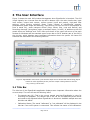
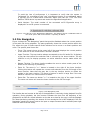
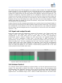
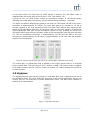
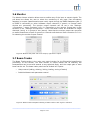
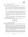
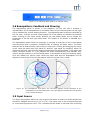
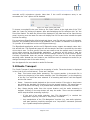
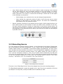
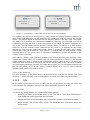
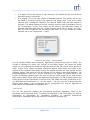
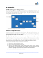
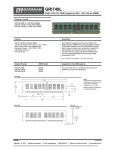
USER MANUAL EigenStudio ® Version 1 Rev. A mh acoustics LLC 25A Summit Ave Summit, NJ 07901 USA Phone: +1 908-277-3131 FAX: +1 908-934-9233 www.mhacoustics.com _________________________________________________________ Copyright ® 2010-2014 mh acoustics LLC. All rights reserved. Eigenmike and EigenStudio are trademarks of mh acoustics. Apple, Boot Camp, FireWire, Mac, MacBook Pro, OS X and Retina are trademarks of Apple Inc. Microsoft, Windows, Windows XP and Windows 7 are trademarks of Microsoft. ASIO is a trademark and software of Steinberg Media Technologies GmbH. TASCAM is a trademark of the TEAC CORPORATION. _________________________________________________________ Page 2 of 33 _________________________________________________________ Table of Contents 1 Introduction ...................................................................................................................... 5 2 Installing and running EigenStudio .................................................................................... 5 3 The User Interface ............................................................................................................. 6 3.1 Title Bar .................................................................................................................................. 6 3.2 File Navigation ........................................................................................................................ 7 3.3 Input and output levels ........................................................................................................... 8 3.4 Volume Control ....................................................................................................................... 8 3.5 Highpass .................................................................................................................................. 9 3.6 Monitor ................................................................................................................................. 10 3.7 Beam Tracks .......................................................................................................................... 10 3.7.1 Beam Tracks Control .............................................................................................................. 11 3.7.2 Individual Beam Tracks .......................................................................................................... 11 3.8 Beampattern: Feedback and Steering .................................................................................... 13 3.9 Input Source .......................................................................................................................... 13 3.10 Audio Transport .................................................................................................................... 14 3.11 Recording Source .................................................................................................................. 15 3.12 Menus ................................................................................................................................... 16 3.12.1 Settings ................................................................................................................................ 16 3.12.2 Info ....................................................................................................................................... 17 4 Appendix ........................................................................................................................ 19 4.1 Block Diagram of Signal Flow ................................................................................................. 19 4.2 The Configuration File ........................................................................................................... 19 4.3 The Highpass Filter ................................................................................................................ 20 4.4 Directivity Patterns ............................................................................................................... 20 4.4.1 Omni ...................................................................................................................................... 21 4.4.2 3rd order super-‐cardioid (super3) ........................................................................................... 22 4.4.3 2nd order super-‐cardioid (super2) .......................................................................................... 23 4.4.4 1st order super-‐cardioid (super1) ........................................................................................... 24 4.4.5 3rd order hyper-‐cardioid (hyper3) .......................................................................................... 25 _________________________________________________________ Page 3 of 33 _________________________________________________________ 4.4.6 2nd order hyper-‐cardioid (hyper2) .......................................................................................... 26 4.4.7 1st order hyper-‐cardioid (hyper1) .......................................................................................... 27 4.4.8 3rd order cardioid (card3) ....................................................................................................... 28 4.4.9 2nd order cardioid (card2) ...................................................................................................... 29 4.4.10 1st order cardioid (card1) ..................................................................................................... 30 4.4.11 1st order dipole (dipole1) ..................................................................................................... 31 4.5 Microphone Positions ........................................................................................................... 32 _________________________________________________________ Page 4 of 33 _________________________________________________________ 1 Introduction mh acoustics' EigenStudio application is the main software application written by mh acoustics for our em32 Eigenmike microphone array. EigenStudio allows for recording processing and control of the em32’s microphone array system. The applications processing capabilities cover a wide range of possible beamforming applications. Multiple output beams can be formed simultaneously, each one having its own spatial characteristic (beampattern) and steering direction (look-direction). EigenStudio can render up to 24 distinct beamformed output channels. Input channels can be selected between either real-time “raw” microphone signals from the em32 array or from previously recorded em32 data. The rendered output channels can be played back through an audio driver (note that the default EMIB configuration only supports a maximum of 8 real-time output channels via an optical ADAT interface) and/or stored to file. The EigenStudio application can be run for processing and playback without an em32 system being connected. When an em32 system is not detected, the EigenStudio application allows the user to select any ASIO (Windows) or Core Audio (OS X) device that is defined on the machine for audio output. To use the PC's internal sound card for output, select e.g. ASIO4ALL (downloadable from the internet1, Windows) or e.g. “Built-In Stereo In/Out” (OS X). 2 Installing and running EigenStudio On pre-configured systems (em32 systems sold with a laptop) mh acoustics has taken care of the installation. The user will find the EigenStudio application in “C:\EM32 Eigenmike\EigenStudio” (Windows) or “\Applications” (OS X). A desktop shortcut is typically also placed on the main screen of both OS’s to allow for quick launch of the application. For downloaded files the user has to perform the installation. Since the EigenStudio application is distributed as a zipped self-contained folder all there is to do is to unzip the folder and copy it to the desired location, e.g. the ones we use for pre-configured systems. Figure 1: The EigenStudio application icon To start the EigenStudio application one clicks or double-clicks (depending on the location of the application) the application icon (Figure 1). The program will start in the state it was last closed. The application provides a pull-down menu listing all available audio interfaces if no em32 Eigenmike array system is connected. Please choose one and click ok. On the first launch EigenStudio will ask for the pool directory location (see section 3.12.1.2 for details). This location can be changed later. EigenStudio is ready to use once the GUI is displayed. 1 Systems shipped with a MacBook Pro and Boot Camp have the ASIO4ALL Windows driver pre-installed. _________________________________________________________ Page 5 of 33 _________________________________________________________ 3 The User Interface Figure 2 shows the main GUI window that appears when EigenStudio is launched. The GUI is split logically into 11 areas from the top left to bottom right: the main timeline bar, input level meters, output level meters, volume control (input and output), high-pass filter settings, signal monitor selection, Beam Tracks (control of beamformed outputs), beampatterns (beam shape and steering), input source (live from the em32 microphones or from a saved file), audio transport control (Stop, Pause, Play, Loop and Record) and Recording channels (microphone inputs, processed output, or both). In addition to the GUI panels there are “Settings” and “Info” menu pull-downs in the upper left corner of the main window for Windows and the standard upper screen bar on OS X. Another part of the GUI is the title bar, which displays some important information about the system. All these GUI elements are described in the following sections. Figure 2: EigenStudio main screen (note that the Input Source shows that data is being played back from a file (Dylanesque.wav) and the output is being written to the file “out_112414_110037.wav”. 3.1 Title Bar The title bar of the EigenStudio application displays some important information about the current setup. The user will see the following items: • The sample rate (fs): This is the current sample rate that EigenStudio is using for recording and playback. The sample rate is set via the corresponding audio driver and needs to be adjusted before EigenStudio is launched. Available sample rates are 44.1kHz and 48kHz. • Calibration Status: The words “calibrated” or “not calibrated” will be displayed in the title bar if an em32 system is connected. This reflects the status of the calibration. _________________________________________________________ Page 6 of 33 _________________________________________________________ To avoid the loss of performance it is important to verify that the system is “calibrated” for recordings of the “raw” microphone signals. A non-calibrated status is typically due to a failed MIDI connection. Make sure that the “TCAT Dice EVM Platform” MIDI device is present and restart the EigenStudio application. • Serial Number: The serial number of the connected em32 Eigenmike array is displayed if an em32 system is connected. Figure 3: The title bar of the EigenStudio application. This instance shows a calibrated state of the em32 system with serial number 0 operating at 48kHz. 3.2 File Navigation Figure 4 shows the “File Navigation” panel that provides feedback about the current position in the audio file during playback. The pane graphically shows the current position within the file, allows the user to select specific audio sections and to move to a certain position and more. The specific panel items are: • Timer: The numeric timer at the upper left of the panel displays the current position in the audio file in the format hours: minutes: seconds. • Upper Timeline: The top timeline always corresponds to the full audio file. It displays a gray bar that reflects the selection that is covered by the lower timeline. The top timeline is only for display purposes, no active selections can be made within the bar. • Bottom Timeline: The lower timeline enables the user to select certain parts of the audio file for listening or processing. • Zoom In: The zoom-in “<>” button is located to the right of the lower timeline. Clicking this button will expand the current audio selection over the full length of the lower timeline. Note that the gray bar in the top timeline shrinks to reflect the update in the lower timeline. The zoom-in feature is useful in large files if the user wants to narrow in on a short section of audio. • Zoom Out: The zoom-out button “><“ is located to the right of the upper timeline. The zoom-out button will reset the lower timeline to the full file length. Figure 4: File Navigation panel The timeline bar and counter at the top of the application is used only during playback from file operation. During playback, the time counter indicates the time from the beginning of the playback file as well as a visual indication on the bar as to how far the user is into the playback file. Note that during recording, the amount of time recorded so far is NOT displayed in the File Navigation” panel but is shown next to the input or output file name that is selected (lower right hand side next to the file name). _________________________________________________________ Page 7 of 33 _________________________________________________________ One useful feature of the “File Navigation” is to select a section of audio. The “Audio Transport” buttons (section 3.10) at the bottom of the UI will now act only on the selected part of the audio. Selecting a section of audio is done by "rubber-banding" a time selection in the lower timeline bar (holding down the left mouse button and dragging it along the timeline bar). The selection is marked by a light blue colored bar. For example to select the audio from 0:20 minutes to 0:40 minutes (compare Figure 4) the user left-clicks inside the lower timeline at position 0:20, then drag the mouse to end position 0:40 and release the mouse button. Playback will loop over this defined time range until either the user stops playback or selects another time region of interest. To remove the selection, simply make a new selection or just click anywhere in the lower timeline. Another feature of the file navigation panel allows one to quickly jump to any desired location in the file simply by left clicking at the desired location inside the lower timeline bar. The dark blue bar indicates the current position in the file (if the dark blue bar is not visible this indicates that the audio has been stopped and the current position is at the left end of the selected – light blue – bar). 3.3 Input and output levels Input and output levels are displayed as groups of VU meters in the “Input Levels” and “Output Levels” GUI panels (see Figure 5). There are 32 input meters on the 32 microphones in the em32 array and 24 output meters for up-to 24 simultaneous beamformed outputs. Channel numbers for each level meter are indicated below each meter. The level is displayed in dBFS (with 0 dB PGA gain, 0 dBFS corresponds to approximately 124 dB in SPL). The solid bar represents the RMS level while the thin line shows the peak level. The level indicators will turn red if the level exceeds -9 dBFS. The number above each level meter displays the maximum value that the corresponding channel experienced (peak-hold functionality). Double-clicking on a particular number will reset the peak-hold display for this channel. Double-clicking anywhere else in the level meter group will reset all peak-hold values. Figure 5: Input Levels and Output Levels 3.4 Volume Control The “Volume Control” panel contains two volume sliders; one for the inputs and one for the outputs. The input slider is labeled “Mic PGAs”. It sets the gain of the microphone PGAs (Programmable Gain Amplifiers) that are part of the A/D converters inside the Eigenmike array. This gain is applied to the analog microphone signals before the A/D converter digitizes them. The available range is from -10dB to +30dB. Note that the “Mic PGAs” slider _________________________________________________________ Page 8 of 33 _________________________________________________________ is only active when live input from an em32 system is present. The “Mic PGAs” slider is disabled when the sound input source is set to “File” (see section 3.9). Clicking on the “M” mute button mutes all microphone signals. A red-colored button indicates the muted state. Conversely, a green-colored button indicates, “unmuted”. The em32 microphone elements are rated to less than 1% THD below 130 dB in SPL with a sensitivity of approximately 30 mV/Pa. The input gain has to be reduced to -10 dB to prevent clipping of the A/D converters when the input level reaches the maximum SPL rating of the microphone elements. On the other hand, for low input signals it is advised to apply appropriate PGA gain to the microphone signals to fully exercise the 24-bit A/D converters input range since the dynamic range of the microphones (max SPL with less than 1% THD to microphone self-noise) is approximately 115 dB and the SNR of the A/D converters is approximately 95 dB which is approximately 20 dB less than the dynamic range of the microphones Figure 6: Volume control panel (left with “Live” em32 inputs, right with “File” inputs) The output gain is a digital gain that is applied to the output signal before it is recorded and/or played back. The gain range is from -40dB to +40dB. The output volume is applied to all output signals. See the “Volume” setting in section 3.7.2 about setting the volume for a single channel. 3.5 Highpass The Highpass section controls the setting of a high-pass filter that is applied at the end of the processing chain. The cutoff frequency can be set to off (no high-pass filter), 80 Hz, 160 Hz and 320 Hz. The filters are 6th-order Butterworth filters. The same filter response is applied to all output beams. Figure 7: High-pass GUI panel _________________________________________________________ Page 9 of 33 _________________________________________________________ 3.6 Monitor The Monitor Source selection allows one to audition any of the input or output signals. The pull-down box allows the user to select the monitoring of any input (raw microphone capsules) or output (beamformed output track) signal through the EMIB headphone jack (if an EMIB is connected) or other hardware output channels (if generic or internal audio devices are connected). The monitor output channels can be set in the “Settings>Connection…” menu (compare 3.12.1.1). Depending on the monitor format that is also selected in the “Settings->Connections…” menu the beam tracks are available as single channels (mono) or in groups of two (stereo). Note that the monitor output can overwrite an audio beamformer output for generic or internal audio devices. Refer to section 3.12.1.1 for selecting the monitor output channel. Figure 8: Monitor GUI panel: left mono output; right stereo output 3.7 Beam Tracks The Beam Tracks section is the main user control section for the Eigenmike beamforming processing. In this section, the total number of output beams can be selected, the beampatterns can be set and steered to any spherical angle, and the output gain of each beam can be set. The beam tracks panel can be divided into 2 parts: • Setup control (adding, deleting, linking, loading, saving of tracks) • Individual beam track parameter control Figure 9: Beam Tracks GUI panel showing 3 beam tracks. Track “right” is selected. _________________________________________________________ Page 10 of 33 _________________________________________________________ 3.7.1 Beam Tracks Control The beam track control consists of the 5 buttons (compare Figure 10) at the top of the Beam Tracks panel. These buttons have the following functions: • + : The “+” button adds a new beam track. The new track will be added to the bottom of the track list. It is initially populated with default parameters. The maximum number of beam tracks is 24. Note that a scroll bar will appear to the right side of the beam tracks if there are more tracks than the Beam Tracks panel can show. • - : The “-” button deletes the currently selected track. To select a track simply click on it. • L : The “L” (linked) button links the azimuth parameter of all tracks. All tracks will rotate by the same amount if one beam is steered horizontally (azimuth) and the “Link” state is active. A yellow-colored “Link” button indicates an active “Link” state. • : This is a “Save” button. It saves the current beam track configuration to a file. After clicking the button the user will be asked to enter a name for the current configuration. A saved configuration can be loaded at any time via the “Load” button (see next item). • : This is a “Load” button. Use this to retrieve a previously saved beam track configuration setup. A new installation of the EigenStudio application will only have the “default” configuration available. On closing the EigenStudio application the user has the chance to save (and name) the current configuration if any changes were made to the last state saved. Figure 10: Beam track control 3.7.2 Individual Beam Tracks The individual beam tracks (compare Figure 11) control the parameter settings. For each track the following parameters are available: • Azimuth: This is the look-direction (direction with maximum sensitivity) of the beam in the horizontal plane. The number is in degrees and ranges from 0 to 359. 0 degrees aligns with the “mh acoustics” logo on the shaft of the Eigenmike. The angle increases in the counter-clockwise direction. There are two ways to change the direction: a) double click the number in the beam track (a dialog will pop up where the user can change the angle by entering the number or by using the up/down arrows) or b) a selected beam can be steered via the “Beam Pattern” panel (compare section 3.8). The azimuth angle can also be steered indirectly via another beam track if the tracks are linked (compare section 3.7.1) • Elevation: This is the look-direction (direction with maximum sensitivity) of the beam in the vertical dimension. The number is in degrees and ranges from 0 to 180. 0 degrees points away from spherical array from the top (the opposite side from where the shaft mounts to the Eigenmike). 90 degrees is the horizontal plane and _________________________________________________________ Page 11 of 33 _________________________________________________________ 180 degrees in the direction of the shaft. As with steering the azimuth, there are two ways to change the direction: a) double click the number in the beam track (a dialog will pop up where the user can change the angle by entering the number or by using the up/down arrows) or b) a selected beam can be steered via the “Beam Pattern” panel (compare section 3.8). • Pattern: The beampattern describes the direction dependent sensitivity of the microphone. EigenStudio allows the choice between 12 different possible beampatterns: cardioid (1st, 2nd and 3rd order), super-cardioid (1st, 2nd and 3rd order), hyper-cardioid (1st, 2nd and 3rd order), omni, 1st order dipole and torus. See the Appendix for more details on the beam patterns. • Specification: The specification represents a measure related to allowable increase in the signal-to-noise ratio (SNR) of the beamformer output2. More negative values (lower SNR) of the specification allow the beamformer to increase spatial selectivity at lower frequencies with the tradeoff of a lower SNR. The available values for the specification depend on the beam pattern selection. The higher-order beam patterns provide 5 values (-12, -6, 0, 6, 12) while the other one’s have a fixed specification setting. • Volume: The output volume for each beam track can be adjusted between -20dB and +20dB. Double-click on the volume display in the beam track to change the volume. A window with a slider will open. Multiple sliders can be open simultaneously to simplify the relative volume adjustments of the beam tracks. The label above the slider will identify the beam track it belongs to. • Mute: This is the track mute button. In the muted state (red button) the output signal for the corresponding beam track is muted. • ID color: Beam tracks are identified by their color and label. The color is shown in the small oval on the right side of the beam track or – for a selected track – the whole background shows the track color. Double-clicking in the oval area allows one to set the desired track color. • Label: The label allows the user to identify the beam track, e.g. ‘left’, ‘right’. The default labels are ‘beam X’ where X is a number that increases with the number of tracks. Double-clicking on the white label background allows the user to change the label. 2 More specifically, the specification represents the minimum allowable White-Noise-Gain (WNG) in dB. _________________________________________________________ Page 12 of 33 _________________________________________________________ Figure 11: An individual beam track (in a “marked” state). 3.8 Beampattern: Feedback and Steering The beampattern panel is shown in two diagrams. On the left side it displays a representation of the beampatterns for the beam tracks in the horizontal plane. On the right side it indicates the vertical steering direction. Corresponding beam tracks are identified by the line color. A thicker line and a semi-opaque fill of the pattern will indicate the selected beam. Clicking on the center border between the two panels allows one to change the proportions of the left and right panel areas. The location of the border is indicated by a small dot. The beampattern panel fulfills two purposes: it provides an overview of the current spatial recording setup and it provides a simplified way of steering the beam tracks. The beam patterns can be steered either continuously or step-wise. Clicking and dragging the mouse curser inside the panel area (left panel for azimuth, right panel for elevation) allows for continuous steering. Note that the steering operates on the selected beam. If the tracks are linked (compare section 3.7.1) all patterns will rotate simultaneously and maintain their relative angular positions in the horizontal plane. To accomplish a step-wise steering simply click and release the mouse curser inside the panel area and the beampattern will be aligned to the direction of the mouse position when the mouse-click is made. Figure 12: The beampattern GUI panel. The left polar diagram shows facsimiles of the beampattern in the horizontal plane. The right diagram indicates the look-direction in the vertical dimension. 3.9 Input Source The Input Source panel allows the user to select the source of where the audio samples are streamed. Available sources are “Live” or “File”. Live inputs refer to the microphone signals of a connected Eigenmike em32. “File” indicates that the audio is retrieved from previously _________________________________________________________ Page 13 of 33 _________________________________________________________ recorded em32 microphone signals. Note that if the em32 microphone array is not connected the “Live” option will be disabled. Figure 13: Input source GUI panel. To choose a recorded file the user clicks on the “open” button to the right side of the “File” label. An “open file” dialog will appear. After acknowledging the file selection with “ok” the file will be loaded. The base file name will be displayed in the label area of the Input Source panel. Hovering over the base file name will display the full file name that includes the path and the file ending. For convenience EigenStudio will also load and play a .wav file with any number of channels. However, all processing elements will be disabled if the number of channels is not equal to 32 (number of microphones in the em32 Eigenmike array). The EigenStudio application and the em32 Eigenmike array support two sample rates: 44.1 kHz and 48 kHz. The EigenStudio app will use the sample rate that is provided by the audio driver that it uses. To set a specific rate the user needs to set the sample rate in the audio driver before opening the EigenStudio application. A warning will be given in case the sample rate of the connected audio driver and the sample rate of an input file don’t agree. Currently EigenStudio does not provide resampling of the input file to the two allowed sampling rates. Instead the user needs to use a different tool to resample the audio file (or change the sample rate of the audio driver). See the Appendix for more detail on audio file formats. 3.10 Audio Transport The “Audio Transport” panel controls the streaming of audio. The active button is displayed in blue (red for the record button). There are 5 buttons: • Stop: This button stops audio streaming. The current position in the audio file is reset to the beginning of the audio selection (see “File Navigation”) or the beginning of the file if no audio has been selected. If a recording was active it will be stopped and the file closed. • Pause: Pauses the audio playback at the current location. If the play or loop button are clicked the playback will continue from the paused location. The pause has no effect on an active recording. In a paused audio situation silence will be recorded. • Play: Starts playing audio from the current location until the audio streaming is stopped. Clicking on the stop button will stop the audio. There are also situations which stop the audio streaming implicitly: o If the end of an audio selection (see “File Navigation”) is reached the application implicitly executes a “stop audio” command. o Any manipulation of the “File Navigation” timeline (e.g. new audio selection, new start position) implicitly executed as a “stop audio” command (followed by a “update start/current position”). _________________________________________________________ Page 14 of 33 _________________________________________________________ • • Loop: Starts playing audio from the current location. Audio streaming that is started via the loop button can only be stopped explicitly via the stop button. All implicit “stop audio” situations as listed for the play button is implicitly followed by a “play audio” command. This results in a continuous streaming of audio and can be helpful in the following use scenarios: o While looping over a selection the user can change the parameters o When looking for a particular section of audio in a file the user can try a new position by left-clicking in the lower timeline. The audio will automatically start playing from the selected location. Record: Initiates recording of the selected source signals. Audio streaming has to be active before audio can be recorded. It does not matter which condition is met first, the active audio streaming (via play or loop button) or the active record button. As soon as the record button is clicked a new file name will automatically be generated and displayed in the Recording Source panel (note that the file name can be changed by double-clicking it) Figure 14: Audio Transport panel 3.11 Recording Source The user selects the desired recording signals in the Recording Source panel. Signals that can be recorded are the raw microphones “32 mic. inputs” and the processed beampattern outputs “beam tracks”. It is possible to record both signals simultaneously. As soon as the user activates the Record button (see section 3.10) the EigenStudio application generates a default name for the selected recording source. The default names will have a prefix of “mic” (for the microphone inputs) or “out” (for the beam tracks) followed by the date and time when the record button was clicked. The file name can be changed by double-clicking on the file nameand entering in a new name. All recorded data is stored in the “pool directory”. See section 3.12.1.2 for details on the “pool directory”. Figure 15: Recording Source GUI panel The timer in the “Recording Source” shows the elapsed time since the recording started. The EigenStudio application records the signals into a .wav file using a resolution of 24 bits per sample. For large files (>4GB) the RF64 wav file standard is used. _________________________________________________________ Page 15 of 33 _________________________________________________________ 3.12 Menus 3.12.1 Settings Via the Settings pull-down menu item towards the left of the top menu bar the user has access to the following settings items: • “Connections…”: Under this menu the user can select the active audio channels and the routing of the monitor channels. • “Pool Directory…”: Here the user can select the location of the pool directory. The “Pool Directory” is the folder in which all recordings are stored. 3.12.1.1 Connections The “Connections…” menu is displayed as a tabbed dialog box. The content of this dialog depends on the connected hardware. Figure 16 shows the dialog with the mh acoustics’ EMIB box connected. In Figure 17 the dialog box is shown as it appears with generic or built-in audio hardware. The “EMIB Output” tab (see Figure 16, left) lists the available output options. At a minimum, the ADAT output group is shown. If the system contains the optional 8-channel line output board (“EMIB 8-LO”) it is listed here as well. The user can activate/deactivate output groups and set the order. For example, with the setting as displayed in Figure 16, the beamformer output tracks 1-8 will be routed to the ADAT output and the beamformer output tracks 9-16 will be routed to the EMIB 8-LO line-out card. Figure 16: “Connections…” dialog tabs with EMIB hardware attached. The generic connected hardware output tab (Figure 17, left) enables the user to select the number of audio outputs as well as the channel offset for other audio hardware. The “Channel Offset” determines the hardware channel index that will receive the first beamformer output track. Note that the sum of “Number of channels” and “Channel offset” cannot be larger than the maximum number of channels supported by the connected audio hardware. Note that the number of beam tracks can be larger (up to 24). Only the first N channels will be played where N is the number of output channels. _________________________________________________________ Page 16 of 33 _________________________________________________________ Figure 17: “Connections…” dialog tabs with generic (or built-in) hardware. The monitor tab (Figure 16 and Figure 17, right) selects the output hardware channels (in case of the EMIB hardware this will always be the headphone) that will receive the monitor signal. The monitor signal is selected via the “Monitor” panel in the main GUI. The output will always be 2 channels (for convenient headphone listening). For the EMIB this will be headphone left/right jack that is on the front panel of the EMIB. For generic hardware this will be the “Channel offset” channel and the “Channel offset” +1 channel (e.g. with channel offset set to 0 the monitor output channels will be 0 and 1). In addition to the output channel the user can also select the format: mono or stereo. In the mono case a single beamformer track (or microphone input channel) is played back on both monitor output channels while for the stereo case 2 consecutive beamformer tracks are copied to the monitor output channels. Note that for generic audio playback hardware the monitor channels can overwrite some beamformer output tracks. For example with the settings depicted in Figure 17 the monitor output channels 0 and 1 overwrite the beamformer output tracks 0 and 1. To avoid this make sure that monitoring is not active (set via the Monitor panel of the main GUI) or select non-overlapping hardware channels for output and monitor, e.g. for the above example set the “Monitor offset” to 17 or the output “Channel offset” to 2. This of course requires hardware with a sufficient channel count. 3.12.1.2 Pool Directory The pool directory is the folder where all recorded audio files will be stored. The “Pool Directory…” menu will bring up a file dialog where the user can select the pool directory. 3.12.2 Info As the name implies the Info menu is really just for info purposes. The user can check the audio settings and calibration values of the connected em32 Eigenmike array. 3.12.2.1 Audio The Audio info dialog displays the fundamental audio settings: • Audio Driver: Name of the audio driver in use. This will be “TCAT Dice EVM Platform” if the EMIB and em32 Eigenmike are connected. • Samplerate: the current sampling rate. EigenStudio supports 44.1kHz and 48kHz. • Buffer Length: The current buffer length. See below for more information about the buffer length. _________________________________________________________ Page 17 of 33 _________________________________________________________ • # of inputs: This is the number of input channels. This number will be 32 if the em32 Eigenmike array is connected. • # of outputs: This is the total number of available outputs. This number will be 10 if the EMIB is connected without the optional 8-LO output card. There are 8 ADAT channels and 2 headphone channels. The optional EMIB 8-LO card adds another 8 channels. The actual number of output channels that are used for playback is set in the “Connections…” menu. This number will be equal or less than total number of channels available. Note that the number of beam tracks can be larger (up to 24). Only the first N channels will be played back where N is the number of output channels set in the “Connections…” menu. Figure 18: The “Audio…” settings dialog. Like all computer-based audio programs, EigenStudio processes the audio in blocks. The number of samples in a block (per channel) is the buffer length. The longer the buffer length the more efficient the processing becomes and the less likely there will be glitches in audio. Longer buffer lengths increases robustness against audio issues but comes at the expense of an increased audio delay through the system between the input signals and the playback signals. This delay will only be relevant for live setups (record and playback). For processing/playback from file or simply recording of live signals the system delay is not critical. On Windows based systems the user can set the buffer length via the audio drivers ASIO Control Panel before starting the EigenStudio application. On OS X based systems the buffer length is set by EigenStudio. It will be either 128 (EMIB and em32 connected) or 512 (no EMIB and em32 connected). If – for any reason – the user runs into problems with the shorter buffer length it can be changed via the configuration file. See the Appendix on details about the EigenStudio configuration file. 3.12.2.2 Cal The Cal info sub-menu displays the microphone amplitude calibration values of the connected em32 Eigenmike array. The values are displayed in dB. These gains are used by EigenStudio to compensate for microphone mismatch to maximize beamformer performance. Calibration values are shown for information purposes only. _________________________________________________________ Page 18 of 33 _________________________________________________________ 4 Appendix 4.1 Block Diagram of Signal Flow The block diagram in Figure 19 shows the signal flow in the EigenStudio application. All blocks inside the blue area are implemented in software in the EigenStudio app. The PGA is the analog gain that is applied to the microphone signals. This gain is controlled from within the EigenStudio application (see section 3.4). Figure 19: Block diagram of signal flow in EigenStudio. 4.2 The Configuration File Note that this section is provided for advanced users. The user should only access the configuration file in two rare events: a) to change the “live” buffer length on OS X systems (see section 3.12.2.1) or b) the file got corrupted (simply delete the file and the EigenStudio app will create a new one the next time it starts). The EigenStudio application stores the last-used settings in the configuration file “EigenStudio.ini”. On Windows-based systems the file is stored in the folder “%AppData%\mh acoustics” under the users home folder. On OS X based systems the file is stored in the folder “~/.config/mhacoustics.com”. The EigenStudio application will check for the existence of the file at startup. The application uses default parameters if no configuration file is present. It will store the file with the last-used settings at closing. To change the audio buffer lengths in OS/X follow these steps: 1. Make sure the EigenStudio app is closed. 2. Open the configuration file with a text editor 3. Locate the entry rtBufferLength. Change the associated number. Smaller numbers mean less delay and less robustness; larger numbers mean more delay and mode robustness. The EMIB allows buffer length between 15 and 3000 samples. 4. Save the modified file and close the text editor. _________________________________________________________ Page 19 of 33 _________________________________________________________ 5. The next time the EigenStudio application starts it will use the new buffer size (Note that this size is only used on OS X systems with an em32 Eigenmike being connected). 4.3 The Highpass Filter Section 3.5 described the highpass GUI panel and its use. Figure 20 shows a plot of the frequency responses of the different highpass filters associated with the different cutoff frequency settings. Figure 20: Frequency response of highpass filters. 4.4 Directivity Patterns This section provides some technical specifications on the available beampatterns in EigenStudio. Frequency-angle sensitivity plots of the directivity, Directivity Index (DI) over frequency, White Noise Gain (WNG) over frequency, 3dB beam-width (BW), beampatterns for some representative frequencies, and three-dimensional beampatterns for two selected frequencies are shown. The data presented here are from ideal simulations and not from measured data. Note that only the 0 dB specification is shown for the beampatterns with multiple specifications. The title for each section has the common name of the beampattern as well as a short name that is used in the pop-up GUI in EigenStudio. _________________________________________________________ Page 20 of 33 _________________________________________________________ 4.4.1 Omni _________________________________________________________ Page 21 of 33 _________________________________________________________ 4.4.2 3rd order super-cardioid (super3) _________________________________________________________ Page 22 of 33 _________________________________________________________ 4.4.3 2nd order super-cardioid (super2) _________________________________________________________ Page 23 of 33 _________________________________________________________ 4.4.4 1st order super-cardioid (super1) _________________________________________________________ Page 24 of 33 _________________________________________________________ 4.4.5 3rd order hyper-cardioid (hyper3) _________________________________________________________ Page 25 of 33 _________________________________________________________ 4.4.6 2nd order hyper-cardioid (hyper2) _________________________________________________________ Page 26 of 33 _________________________________________________________ 4.4.7 1st order hyper-cardioid (hyper1) _________________________________________________________ Page 27 of 33 _________________________________________________________ 4.4.8 3rd order cardioid (card3) _________________________________________________________ Page 28 of 33 _________________________________________________________ 4.4.9 2nd order cardioid (card2) _________________________________________________________ Page 29 of 33 _________________________________________________________ 4.4.10 1st order cardioid (card1) _________________________________________________________ Page 30 of 33 _________________________________________________________ 4.4.11 1st order dipole (dipole1) _________________________________________________________ Page 31 of 33 _________________________________________________________ 4.5 Microphone Positions The microphones are numbered in a pattern that is convenient for assembly of the em32 Eigenmike array. Table 1 shows the spherical angles in degrees for each microphone channel. The azimuth angle phi counts counter clockwise. Zero degrees in azimuth aligns with the “mh acoustics” logo on the microphone shaft. The elevation angle theta increases from the top (away from the shaft) to the bottom (aligned with the shaft). The radius of the em32 Eigenmike array is 42 mm. Microphone Theta Phi 1 69 0 2 90 32 3 111 0 4 90 328 5 32 0 6 55 45 7 90 69 8 125 45 9 148 0 10 125 315 11 90 291 12 55 315 13 21 91 14 58 90 15 121 90 16 159 89 17 69 180 18 90 212 19 111 180 _________________________________________________________ Page 32 of 33 _________________________________________________________ 20 90 148 21 32 180 22 55 225 23 90 249 24 125 225 25 148 180 26 125 135 27 90 111 28 55 135 29 21 269 30 58 270 31 122 270 32 159 271 _________________________________________________________ Page 33 of 33