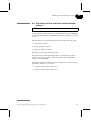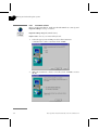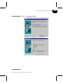
1
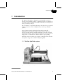
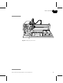
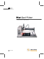
user manual
proteomics
Instrument Handbook
um 18-1147-62
Important user information
All users must read this entire manual to fully
understand the safe use of EttanTM Spot Picker.
WARNING!
The Warning sign highlights an instruction
that must be strictly followed in order to avoid
personal injury. Be sure not to proceed until
the instructions are clearly understood and all
stated conditions are met.
Caution!
All goods and services are sold subject to the terms and
conditions of sale of the company within the Amersham
Biosciences group which supplies them. A copy
of these terms and conditions is available on request.
Ettan, ImageMaster, ImageScanner, PlusOne,
GelBond and Typhoon are trademarks of Amersham
Biosciences Limited.
Amersham and Amersham Biosciences are trademarks
of Amersham plc.
Gilson is a trademark of Gilson Inc.
The Caution sign is used to call attention to
instructions or conditions that must be
followed to avoid damage to the product or
other equipment. Be sure not to proceed until
the instructions are clearly understood and all
stated conditions are met.
Declaration of conformity
Safety standards
This product meets the requirements of the Low Voltage
Directive 72/23/EEC through the harmonized standard
EN 61 010-1:1993 + A2:1995.
EMC standards
This product meets the requirements of the EMC
Directive 89/336/EEC through the harmonized
standards EN 50081-1 and EN 50082-1.
Coomassie is a trademark of Imperial Chemical
Industries PLC.
Decon is a trademark of Decon Laboratories Limited.
SYPRO is a trademark of Molecular Probes Inc.
Matrox is a trademark of Matrox Electronics
Systems Ltd.
Microsoft and Windows NT are trademarks of
Microsoft Corp.
Sony is a trademark of Sony corporation.
©Amersham Biosciences AB 2000
-All rights reserved
WARNING!
This is a Class A product. In a domestic environment,
this product may cause radio interference, in which case
the user may be required to take adequate measures.
Office Addresses
Amersham Biosciences AB
The CE symbol and corresponding declaration of
conformity is valid for the instrument when it is:
SE-751 84 Uppsala
Sweden
–
used as a stand-alone unit, or
–
connected to other CE-marked
Amersham Biosciences
instruments, or
Amersham Place Little Chalfont
Buckinghamshire
England HP7 9NA
–
connected to other products
recommended or described in
this manual, and
Amersham Biosciences Inc.
–
used in the same state as it was
delivered from Amersham
Biosciences except for
alterations described in this
manual.
Amersham Biosciences Europe GmbH
Amersham Biosciences UK Limited
800 Centennial Avenue
P.O. Box 1327 Piscataway N.J. 08855-1327
USA
Munzinger Strasse 9
D-79111 Freiburg
Germany
Amersham Biosciences KK
Sanken Building
3-25-1 Hyakunincho, Shinjuku-ku
Tokyo
Japan
Contents
Contents
1 Introduction
1.1 The Ettan Spot Picker system ....................................................... 9
1.1.1
Rating labels........................................................................ 10
1.2 Package contents ...................................................................... 11
1.3 Accessories ............................................................................... 11
1.4 The Instrument Handbook ......................................................... 12
1.5 Associated documentation ......................................................... 12
2 Safety instructions
2.1 Safety precautions .................................................................. 13
2.2 Safety labels ........................................................................... 14
2.3 Other warnings .......................................................................... 15
2.4 Emergency procedures .............................................................. 16
2.4.1
Emergency shutdown........................................................... 16
2.4.2
Power failure routine ............................................................ 16
2.4.3
Restart procedure ................................................................ 16
3 Basic Operation
3.1 Preparing the instrument ........................................................... 17
3.1.1
Tubing................................................................................. 17
3.1.2
Positioning the gel tray ......................................................... 18
3.1.3
Racks and microplates......................................................... 19
3.2 Selecting a picker head .............................................................. 21
3.3 Starting Ettan Spot Picker .......................................................... 22
3.4 Software user interface .............................................................. 24
3.5 Setting system parameters ......................................................... 25
3.5.1
Moving the picker head around............................................ 26
3.5.2
Camera calibration before picking ........................................ 27
3.5.3
Setting the position of the rinse station ................................. 27
3.5.4
Setting the positions of the microplates................................. 28
3.6 Setting picking parameters ......................................................... 29
3.7 Priming the system .................................................................... 30
3.8 Calibrating the scanner .............................................................. 31
3.8.1
Background......................................................................... 31
3.8.2
Calibration procedure........................................................... 31
4 Maintenance
4.1 Introduction ............................................................................... 33
4.2 Cleaning procedures .................................................................. 33
4.2.1
Cleaning the instrument regularly ......................................... 33
4.2.2
Cleaning the instrument after spot picking............................ 34
Ettan Spot Picker Instrument Handbook 18-1147-62 Edition AA
v
Contents
4.3 Changing picker head ............................................................... 35
4.3.1
Removing the picker head ................................................... 35
4.3.2
Attaching a new picker head................................................ 36
4.4 Calibrating the camera .............................................................. 37
4.4.1
Required accessories .......................................................... 37
4.4.2
Focusing the lens ................................................................ 37
4.4.3
Calibration procedure .......................................................... 38
4.5 Replacing the mains fuse .......................................................... 41
4.6 Preventive maintenance ............................................................ 42
5 Troubleshooting
5.1 Diagnostics ............................................................................... 44
5.2 Troubleshooting ........................................................................ 46
6 Moving and reinstalling the system
6.1 Site requirements ...................................................................... 47
6.1.1
Bench space ....................................................................... 47
6.1.2
Environment........................................................................ 47
6.1.3
Power requirements ............................................................ 48
6.1.4
Media supply....................................................................... 48
6.2 Moving the instrument .............................................................. 48
6.3 Reinstalling the Ettan Spot Picker .............................................. 50
6.3.1
Electrical connections.......................................................... 50
6.3.2
Power-up check .................................................................. 52
6.3.3
Camera calibration .............................................................. 52
6.3.4
Shutdown............................................................................ 52
6.4 Reinstalling the Ettan Spot Picker Instrument Control Software. .. 53
6.4.1
Instrument software............................................................. 54
6.4.2
Frame grabber software....................................................... 55
6.4.3
Ettan Spot Picker Software................................................... 58
7 Reference information
7.1 The Spot Picker Instrument ....................................................... 59
7.1.1
Front panel.......................................................................... 60
7.1.2
Connectors.......................................................................... 62
7.1.3
The picker head .................................................................. 63
7.1.4
Video camera ...................................................................... 64
7.2 Specifications ............................................................................ 65
7.2.1
Technical specification ........................................................ 65
7.2.2
Performance specification ................................................... 65
7.2.3
Regulatory requirements...................................................... 66
7.3 Ordering information ................................................................. 67
7.3.1
Accessories ......................................................................... 67
7.3.2
Related products ................................................................. 68
vi
Ettan Spot Picker Instrument Handbook 18-1147-62 Edition AA
List of figures
List of figures
Fig 1-1.
Fig 1-2.
Fig 2-1.
Fig 3-1.
Fig 3-2.
Fig 3-3.
Fig 3-4.
Fig 3-5.
Fig 3-6.
Fig 3-7.
Fig 3-8.
Fig 3-9.
Fig 3-10.
Fig 3-11.
Fig 4-1.
Fig 4-2.
Fig 4-3.
Fig 4-4.
Fig 5-1.
Fig 6-1.
Fig 6-2.
Fig 6-3.
Fig 7-1.
Fig 7-2.
Fig 7-3.
Fig 7-6.
Fig 7-7.
Fig 7-8.
Fig 7-9.
The Ettan Spot Picker system....................................................... 9
Location and layout of rating labels. ........................................... 10
Safety label located on the Y-arm, near the picker head. ............ 14
Spot Picker tubing setup............................................................ 18
Placing the gel tray on the locator plate. ..................................... 18
Positioning the gel tray............................................................... 19
Fastening the gel. ...................................................................... 19
Placing a microplate rack on the locator plate. ........................... 20
Installing microplates in the racks, well A1 marked..................... 20
The picker head. ....................................................................... 21
Homing the picker head. ........................................................... 23
The Ettan Spot Picker main application window.......................... 24
The System Setup screen. ......................................................... 25
The numbering of the microplates.............................................. 28
The picker head. ....................................................................... 35
Final appearance of the assembled picker head......................... 36
Accessories for camera calibration. ............................................ 37
Replacing the mains fuse........................................................... 41
Typical error message................................................................ 43
Electrical connectors.................................................................. 50
Communications settings on the Ettan Spot Picker. .................... 51
Ettan Spot Picker software installation, start screen. ................... 58
The Ettan Spot Picker. ............................................................... 59
Locator plate with gel tray. ......................................................... 60
Indicators and controls on the front panel. ................................. 60
Rear panel with mains power connector..................................... 62
The picker head. ....................................................................... 63
Spring action when lowering the picker head.............................. 63
The video camera. ..................................................................... 64
Ettan Spot Picker Instrument Handbook 18-1147-62 Edition AA
vii
1
Introduction
1 Introduction
The Ettan™ Spot Picker is designed to automatically excise and
transfer polyacrylamide gel plugs, containing proteins, from 2D gels to
microplates. These gel plugs are suitable for further processing prior to
mass spectrometry analysis.
The Spot Picker is compatible with 2D gels that have been post-stained
with Coomassie™, silver or SYPRO™ dyes, and for pre-labelled
proteins.
Spots of interest can be evaluated and selected by using the
ImageMaster™ 2D Elite gel image analysis software. A pair of
reference markers must be included within the gel and also detected
during image analysis. These reference markers are used to transform
image (pixel) co-ordinates into distance values for spot picking.
Following excision from the gel, gel plugs are dispensed into 96-well
microplates, along with a volume of dispensing fluid.
1.1 The Ettan Spot Picker system
Fig 1-1. The Ettan Spot Picker system.
Ettan Spot Picker Instrument Handbook 18-1147-62 Edition AA
9
1
Introduction
The Ettan Spot Picker system comprises the following:
• Ettan Spot Picker instrument
• Ettan Spot Picker instrument control software, running under
Windows NT operating system on a PC
• PC with frame grabber card for video display
The package contents are described in Section 1.2. A detailed
description of the Ettan Spot Picker instrument is provided in
Chapter 7 of this manual.
250J0449
1.1.1 Rating labels
A rating label is located on the rear panel of the Ettan Spot Picker
instrument, see Fig. 1-2. Pay attention to the component ratings. These
ratings determine the degree of electrical hazards in the equipment
connected to the supply voltage. There are, however, other hazards,
which may be more severe, see Chapter 2 Safety instructions.
Fig 1-2. Location and layout of rating labels.
10
Ettan Spot Picker Instrument Handbook 18-1147-62 Edition AA
1
Introduction
1.2 Package contents
The Ettan Spot Picker instrument is delivered with the products listed
in Table 1-3 . Picker heads can be ordered separately, see ordering
information in Chapter 7.
Product
Quantity
Ettan Spot Picker Instrument Control Software
1
Picker head 1.4 mm for 1 mm thick gels
2
Picker head 1.4 mm for 1.5 mm thick gels
2
Reference markers, sheet incl. 560 pieces
2
Gel holder
2
Gel tray
1
Glass lid for gel tray
1
Inlet tubing package
1
Waste bottle and tubing
1
Accessories for camera calibration:
camera calibration foot
white sheet for camera calibration and click-and-pick
function
5
2
Microplate rack
2
RS 232 cable
1
Table 1-3. Ettan Spot Picker, delivered products.
1.3 Accessories
In addition to the items delivered with the system, Ettan Spot Picker
requires the following accessories:
• image scanner: Image Scanner or Typhoon*
• gel image evaluation software, e.g. ImageMaster 2D Elite
• 96-well microplates
See Chapter 7 for specifications and ordering information.
*If you want to use other scanners, please contact Amersham
Biosciences.
Ettan Spot Picker Instrument Handbook 18-1147-62 Edition AA
11
1
Introduction
1.4 The Instrument Handbook
This handbook provides safety instructions, technical information and
basic operating instructions for the Ettan Spot Picker instrument.
In addition, maintenance schedules and instructions for user
maintenance are included.
1.5 Associated documentation
The Ettan Spot Picker User Manual describes the experimental use of
the instrument, and includes descriptions of all software dialogues.
GilsonTM 215 Liquid Handler User’s Guide describes the unmodified
instrument and contains technical specifications and instructions for
installation and maintenance. Reference will be made to instructions
located in the User’s Guide.
The SonyTMBlack-and-White Video Camera Module XC-55/55BB
Operating Instructions describes the camera.
The MatroxTM Meteor-II Installation and Hardware Reference manual
describes the frame grabber board and provides installation
instructions.
12
Ettan Spot Picker Instrument Handbook 18-1147-62 Edition AA
2
Safety instructions
2 Safety instructions
IMPORTANT! To avoid any risk of injury, the instrument should only
be operated by properly trained personnel and always in accordance
with the instructions provided.
The purpose of this chapter is to describe safety precautions and
present all safety labels that are attached to the instrument. Built-in
safety functions are described, and emergency and disposal procedures
are included.
2.1 Safety precautions
1
Read this entire manual before using the Ettan Spot Picker
instrument.
2
This instrument is designed for indoor use only.
3
The instrument must always be used with the protective earth lead
of the power cord correctly grounded to earth at the mains outlet.
4
To permit sufficient cooling, ensure that the vents at the top and
bottom of the instrument are not covered.
5
Do not operate the instrument in extreme humidity (above 95%).
Avoid condensation by letting the unit equilibrate to ambient
temperature.
6
Do not operate the instrument in direct sunlight.
7
Keep the instrument dry and clean. Wipe regularly with a soft damp
tissue. Let the instrument dry completely before use.
8
Any equipment connected to the instrument should meet the
requirements of the EN 61 010-1 or other international safety
standards.
WARNING! Do not use the Ettan Spot Picker in any other way than
described in this Instrument Handbook. The protection provided by
the instrument may be weakened if other operations are performed.
Ettan Spot Picker Instrument Handbook 18-1147-62 Edition AA
13
2
Safety instructions
2.2 Safety labels
The following safety labels are attached to the Ettan Spot Picker
instrument to warn the user of potentially hazardous conditions:
At the picker head
Fig 2-1. Safety label located on the Y-arm, near the picker head.
WARNING! MOVING PARTS. The picker head and camera assembly
can make sudden, rapid movements. Keep all body parts clear when
the Spot Picker is in operation.
WARNING! Never put your hands underneath the picker head during
instrument operation. The picker head has the capacity to puncture
skin. In the event of an emergency, press the Stop button on the Spot
Picker: the instrument immediately ceases movement and all motors
are de-energized.
WARNING! To prevent fire or shock hazard, do not spill liquids into
the camera body.
14
Ettan Spot Picker Instrument Handbook 18-1147-62 Edition AA
2
Safety instructions
2.3 Other warnings
WARNING! HEAVY OBJECT. The Ettan Spot Picker weighs about 40
kg. Two persons are required to lift the instrument.
WARNING! NO SERVICEABLE PARTS INSIDE. Do not open covers.
Service and maintenance should be performed by qualified
personnel.
Ettan Spot Picker Instrument Handbook 18-1147-62 Edition AA
15
2
Safety instructions
2.4 Emergency procedures
2.4.1 Emergency shutdown
In the event of an emergency, press the Stop button on the Ettan Spot
Picker front panel. The instrument immediately ceases movement and
all motors are de-energized.
2.4.2 Power failure routine
In the event of a power failure, the experiment is interrupted in an
undefined state. However, the data for gel plugs picked, up to the power
interruption, is saved.
When power returns, this will happen:
1
The picker head and the syringe pump (dilutor) are homed.
2
The PC starts and displays the log-in dialogue.
2.4.3 Restart procedure
In the event of system shutdown due to power failure, emergency stop
or process interruption, malfunctions must be rectified before the Ettan
Spot Picker is restarted.
To restart the Ettan Spot Picker:
1
Check that the Power indicator on the Ettan Spot Picker instrument
lights.
2
Select Programs:Ettan Spot Picker:Ettan Spot Picker from the Windows
Start menu.
3
Reload the result file and continue picking, see instructions in Ettan
Spot Picker User Manual, Chapter 6, Section Resume picking after
Ettan Spot Picker has been stopped.
Note: The last picked gel plug may be lost. This depends on the exact
moment when the interruption occurred.
16
Ettan Spot Picker Instrument Handbook 18-1147-62 Edition AA
3
Basic Operation
3 Basic Operation
This chapter provides basic operating instructions for the Ettan Spot
Picker instrument, including starting, stopping and preparing for gel
loading. Refer to the Ettan Spot Picker User Manual for instructions on
picking gels.
It is assumed that the instrument and the PC have been correctly
installed by Amersham Biosciences personnel.
3.1 Preparing the instrument
CAUTION! Cleanliness is very important for subsequent analysis of
the gel plugs. Always wear protective gloves when handling gel and
microplates.
WARNING! The picker head and camera assembly can make
sudden, rapid movements. Make sure that power to the Spot Picker is
disconnected while working with the gel tray, racks and picker head.
Plumbing connections:
See Gilson 215
Liquid Handler User’s
Guide, Installation
chapter.
3.1.1 Tubing
Before starting a run, a liquid supply of double-distilled water, or the
wash/destain buffer must be connected to the picker head, via the
syringe pump. The waste tube from the rinse station should be
connected to a waste bottle, placed beneath the instrument (see Fig.
3-1).
The liquid is used for aspirating gel plugs and dispensing them into the
wells of the microplates. The picker head is rinsed in liquid at the rinse
station between each pick.
Ettan Spot Picker Instrument Handbook 18-1147-62 Edition AA
17
3
Basic Operation
Inlet tubing
Stop
Valve
Liquid supply
Syringe pump
Waste tubing
Fig 3-1. Spot Picker tubing setup.
3.1.2 Positioning the gel tray
Place the gel tray on the left-hand part of the locator plate as shown in
Fig. 3-2. The guide feet on the tray should fit onto pins on the locator
plate. It is only possible to fit the gel tray in one direction, with the
corner-mounted guide feet facing the operator (see Fig. 3-3).
Fig 3-2. Placing the gel tray on the locator plate.
18
Ettan Spot Picker Instrument Handbook 18-1147-62 Edition AA
3
Basic Operation
Fig 3-3. Positioning the gel tray.
The gel to be picked is fastened in the gel tray using adjustable clamps
(gel holders), as shown in Fig. 3-4.
Fig 3-4. Fastening the gel.
3.1.3 Racks and microplates
The gel plugs are collected in microplates, which are placed in two
racks on the right-hand side of the locator plate.
1
Install the racks on the locator plate, aligning the holes on the
underside with the pins on the locator plate (see Fig. 3-5). The rack
label should face the front of the Spot Picker.
2
Place up to four microplates in the racks. Note that well A1 should
face the front of the instrument, see Fig. 3-6.
Ettan Spot Picker Instrument Handbook 18-1147-62 Edition AA
19
3
Basic Operation
Fig 3-5. Placing a microplate rack on the locator plate.
Fig 3-6. Installing microplates in the racks, well A1 marked.
20
Ettan Spot Picker Instrument Handbook 18-1147-62 Edition AA
3
Basic Operation
3.2 Selecting a picker head
Picker heads are available in different sizes for different types of gel. See
Chapter 7 for specifications. If you need to change the picker head,
follow the instructions in Chapter 4, Maintenance. After changing the
picker head, a camera calibration should be performed. Instructions for
calibration can also be found in Chapter 4.
Tube fitting
Piston
Retaining
spring
Exchangeable part with
variable diameter and
height.
Punch
Fig 3-7. The picker head.
Ettan Spot Picker Instrument Handbook 18-1147-62 Edition AA
21
3
Basic Operation
3.3 Starting Ettan Spot Picker
WARNING! The picker head and camera assembly can make
sudden, rapid movements. Keep all body parts clear when the Spot
Picker is in operation.
1
Check that the Spot Picker instrument is connected to the PC (see
Chapter 6 Moving and reinstalling the system).
Note: The Spot Picker control software will not run unless a frame
grabber card is installed in the computer.
22
2
Switch on the mains power at the rear of the instrument.
3
Turn on the PC to which it is connected.
4
To start the Ettan Spot Picker Instrument Control Software, select
Programs:Ettan Spot Picker:Ettan Spot Picker from the Windows Start
menu:
5
The picker head will be moved to the home position when the
software starts. For safety reasons, the user must confirm the
movement before starting:
6
After homing, which takes about 20 seconds, the picker head is
positioned as shown in Fig. 3-8.
Ettan Spot Picker Instrument Handbook 18-1147-62 Edition AA
3
Basic Operation
Stop
205
205
Fig 3-8. Homing the picker head.
Ettan Spot Picker Instrument Handbook 18-1147-62 Edition AA
23
3
Basic Operation
3.4 Software user interface
When the homing procedure is ready, the main application window is
shown. You can control the Spot Picker by using buttons in the
window, and by selecting functions from the pull-down menus at the
top of the screen.
Menu bar
Graphical representation
of the pick list
Co-ordinate
table (picklist)
Camera view
Camera
controls
Picker head
controls
Instrument
controls
Marker detection
window
Spot picking guide
functions
Fig 3-9. The Ettan Spot Picker main application window.
For detailed descriptions of the Ettan Spot Picker software functions,
see Ettan Spot Picker User Manual.
24
Ettan Spot Picker Instrument Handbook 18-1147-62 Edition AA
3
Basic Operation
3.5 Setting system parameters
The following parameters must be set up before starting a picking run:
• The position of the rinse station and the microplates
• The height of the gel backing material (Gel Z-position)
• The parameters used for picking the gel plugs
• The acceptable area range for the reference markers (in pixels)
This section describes the procedures for setting the positions of the
rinse station and the microplates. For instructions on setting
parameters for gel handling, see Ettan Spot Picker User Manual.
To set the Spot Picker parameters choose System:System Setup.
Schematic representation of
the Spot Picker
Picker head movement
controls
Fig 3-10. The System Setup screen.
Ettan Spot Picker Instrument Handbook 18-1147-62 Edition AA
25
3
Basic Operation
3.5.1 Moving the picker head around
It is advisable to press the Go to home button prior to setting any of the
system locations.
The blue arrows on the right hand side of the screen are used to move
the picker head to various positions. By pushing the buttons on the
arrows, the head will move stepwise in the corresponding directions. As
long as a button is pushed, the head will keep moving:
Move X/Y
move the picker head horizontally: the outermost
buttons will move the head in 10 mm steps, the
middle buttons in 1 mm steps and the innermost
buttons in 0.1 mm steps.
Move Z
move the picker head vertically in 5, 1 and 0.1 mm
steps, respectively.
Note: When the picker head is close to the rinse station, the 10 mm step
button can be disabled, since the rinse station is located near the
horizontal limit of the Spot Picker. Use the 1 mm and 0.1 mm
buttons to move the picker head at this stage.
CAUTION! Be careful when using the Move Z buttons; rapidly lowering
the picker head into an object may damage the picker head. If the
picker head hits an obstacle, the motor will be shut off and an error
message will be displayed.
CAUTION! Be careful when using the Move X/Y buttons if the picker is
in a low Z-position. Rapidly moving the picker head into an object may
damage the picker head. Always use the innermost Move X/Y buttons
when adjusting the sideways position at low Z-heights.
The current X/Y/Z-position of the picker head is continuously read
back from the instrument and displayed in the corresponding text
boxes.
Once the picker head is placed appropriately (e.g. in the rinse station),
the location can be stored by pressing the appropriate Set button.
If the Cancel button is pressed, any changes made to the System Setup
will be lost. To retain new System Setup parameters, click on the Save &
Exit button.
26
Ettan Spot Picker Instrument Handbook 18-1147-62 Edition AA
3
Basic Operation
3.5.2 Camera calibration before picking
If the picker head has been replaced, the distance between the camera
and the picker head needs to be calibrated before starting a picking run.
See instructions in Chapter 4.
3.5.3 Setting the position of the rinse station
1 Using the Move X/Y arrow, move the picker head until it is placed
above the centre of the rinse station.
2
Using the Move Z arrow, slowly lower the picker head into the rinse
station.
3
If it appears that the picker head will miss the centre of the rinse
station, adjust the X/Y-position of the picker head as appropriate
and continue to lower the picker head.
4
When the picker head is just above the rinse station, adjust the
X/Y-position so that it is centrally placed.
5
Lower the picker head gently into the rinse station.
6
If a gap is formed at the top of the picker head piston, then the
picker head has been lowered too far. Raise the picker head slightly
so that the gap is no longer present, plus an additional 2 mm.
Too far
Ettan Spot Picker Instrument Handbook 18-1147-62 Edition AA
OK; raise the
picker head 2 mm
from this position
27
3
Basic Operation
7
Press the Set Rinse X/Y/Z button.
3.5.4 Setting the positions of the microplates
The microplates are numbered as illustrated in the System Setup screen.
They should be placed with the A1 well facing the operator. During
System Setup only this well has to be defined for each plate.
Fig 3-11. The numbering of the microplates.
To set the positions of the microplates:
28
1
Using the Move X/Y arrow, move the picker head until it is centrally
placed above the A1 well of microplate 1.
2
Using the Move Z arrow, slowly lower the picker head into well A1.
Ettan Spot Picker Instrument Handbook 18-1147-62 Edition AA
3
Basic Operation
3
The current position of the picker head is continuously read back
from the instrument and displayed in the corresponding text boxes:
4
If it appears that the picker head will miss the centre of the well,
adjust the X/Y-position of the picker head as appropriate and
continue to lower the picker head. When the picker head is in the
A1 well, adjust it so that it is centrally placed.
5
The Z-position of the picker head should be adjusted so that
approx. 2 mm of the tip is within the well. This will enhance the
dispensing efficiency of the spot picker.
6
When the picker head is correctly positioned in the well, press the
Set 1 button.
7
At the first microplate, press the Set Plate Z button—this sets the Zheight for all of the microplates and does not need to be set for each
plate individually.
CAUTION! Raise the picker head before moving to the next A1 well.
8
Repeat steps 1-6 for the remaining microplates, without pressing
the Set Plate Z button.
3.6 Setting picking parameters
Before picking spots from a gel, a number of Picking Parameters must be
set, as well as Gel Z Position and Marker Area. Instructions for these
settings can be found in the Ettan Spot Picker User Manual.
Ettan Spot Picker Instrument Handbook 18-1147-62 Edition AA
29
3
Basic Operation
3.7 Priming the system
Priming the syringe removes any air bubbles in the spot picker tubing
and also rinses the tubing with fresh solution. It is recommended that
5-10 priming strokes are used.
Note: It is important to ensure that the position of the rinse station is
correctly set in the System Setup (see Section 3.5.3), before
priming the system.
30
1
Check that the tube fittings at the valve are properly tightened.
2
Select Tools:Prime Syringe.
3
In the Prime Syringe window, enter the number of priming strokes
and press the Prime button.
4
The Stop button is now enabled and can be used to interrupt the
priming.
Ettan Spot Picker Instrument Handbook 18-1147-62 Edition AA
3
Basic Operation
3.8 Calibrating the scanner
3.8.1 Background
Ettan Spot Picker uses the X/Y-image co-ordinates of protein spots to
determine the location of the gel plugs to be removed. Some imaging
systems have inherent imperfections, which lead to a slightly distorted
gel image. The distortion of the image will lead to a distortion of the
spot positions. The picker head will move to a position which, although
the correct location that it has been sent to, is not representative of the
true location of the protein spot.
To correct for such distortions, the ImageScanner can be calibrated
using a separate software that is included in the ImageScanner
Geometry Calibration Kit. The ImageScanner Geometry Calibration
Tool software corrects for the distortions of the gel image that are
introduced by the imaging equipment, by correcting the pixel coordinates of the spots contained within the pick list.
3.8.2 Calibration procedure
The calibration works in the following way:
• A special calibration sheet is imaged on the scanner
• The location of the spots in the subsequent image of the calibration
sheet is determined
• The image distortion is calculated using the differences between the
known co-ordinates of the calibration sheet and the measured spot
locations
• The image distortion data is stored as a correction table for the
scanner
• A gel pick list that is loaded into the Ettan Spot Picker Instrument
Control Software is modified using the correction table for the
particular scanner that was used when scanning the gel
For detailed instructions, see the documentation on the CD-ROM
included in the ImageScanner Geometry Calibration Kit.
Ettan Spot Picker Instrument Handbook 18-1147-62 Edition AA
31
4
Maintenance
4 Maintenance
4.1 Introduction
Regular maintenance is important for safe and trouble-free operation
of the Ettan Spot Picker. The user should keep the instrument clean
and calibrate the camera whenever a picker head has been replaced.
Preventive maintenance should be performed on a yearly basis by
qualified service personnel.
This chapter provides instructions for user maintenance and service
operations, and a schedule for preventive maintenance.
Contact your Amersham Biosciences representative for more
service information.
WARNING! Never put your hands underneath the picker head during
instrument operation. The picker head has the capacity to puncture
skin. In the event of an emergency, press the Stop button on the front
panel.
WARNING! MOVING PARTS. The picker head and camera assembly
can make sudden, rapid movements. Always switch off mains power
before replacing parts or cleaning the instrument.
4.2 Cleaning procedures
4.2.1 Cleaning the instrument regularly
For proper function, the Ettan Spot Picker should be kept clean and dry.
Chemical stains and dust should be removed.
1
Remove the gel tray and the microplate racks from the locator
plate.
2
Wipe the instrument cover with a soft damp tissue. If needed, use a
mild detergent to remove stains.
3
Clean the gel tray and the microplate racks using a mild detergent.
4
Let the instrument dry completely before use.
Ettan Spot Picker Instrument Handbook 18-1147-62 Edition AA
33
4
Maintenance
4.2.2 Cleaning the instrument after spot picking
When a picking run is completed:
34
1
Remove the gel from the gel tray and store/discard as appropriate.
2
If the gel is to be discarded, scrape the gel off the glass plate with a
plastic spacer or similar object. Then put the plates into a 5%
Decon solution overnight to remove any gel fragments which
adhere to the plate.
3
Rinse the buffer lines with distilled water using the prime syringe
tool.
4
Rinse the liquid out of the gel tray with distilled water and leave the
gel tray to dry.
Ettan Spot Picker Instrument Handbook 18-1147-62 Edition AA
4
Maintenance
4.3 Changing picker head
The Ettan Spot Picker can be used with a range of picker heads, with
varying diameter and height. The picker heads are easily changed by a
simple screw-in/screw-out method. After changing a picker head, a
camera calibration should be performed, to establish the offset between
the picker head and the camera lens. The gel Z-position may also have
to be adjusted in the System Setup.
Retaining spring
O-ring
Punch
Fig 4-1. The picker head.
4.3.1
Removing the picker head
WARNING! Switch off mains power to the Spot Picker before
removing the picker head.
1
When mains power has been switched off, move the picker head to
a convenient position to work in.
2
Hold the top of the picking piston with one hand, and with the
other unscrew the picker head from the base of the piston.
3
When the picker head is completely unscrewed from the base of the
piston, place it in a safe location until it is required once more.
Make sure that the retaining spring is also kept safe.
Ettan Spot Picker Instrument Handbook 18-1147-62 Edition AA
35
4
Maintenance
4.3.2 Attaching a new picker head
1 Place the retaining spring over the screw thread on the top of the
picker head.
2
Screw the picker head onto the base of the piston, making sure that
the screw thread is inside the piston. At the same time, hold the top
of the piston steady with your other hand.
3
Slowly screw the picker head into the piston, while holding the top
of the piston still with the other hand. The picker head only needs
to be tightened to finger tight.
Fig 4-2. Final appearance of the assembled picker head.
Proceed by calibrating the distance between the picker head and the
camera (see Section 4.4).
36
Ettan Spot Picker Instrument Handbook 18-1147-62 Edition AA
4
Maintenance
4.4 Calibrating the camera
4.4.1 Required accessories
You need the following accessories for the camera calibration:
• White sheet for calibration, code no. 18-1143-51
• Camera calibration foot, code no. 18-1143-33
• Double-sided adhesive tape
Fig 4-3. Accessories for camera calibration.
4.4.2 Focusing the lens
Before starting the camera calibration, check that the camera lens is
focused on the bottom of the tray:
Aperture
1
Use the Click and Pick screen for the adjustments: select
Tools:Click ‘n’ Pick.
2
Place the white calibration sheet in the tray.
3
Place an object on the sheet, e.g. a piece of paper with printed text.
4
With the Set Contrast and Set Brightness controls in the centre
positions, adjust the aperture to normal brigthness.
5
Adjust the focus ring on the lens to a sharp picture.
Focus
Ettan Spot Picker Instrument Handbook 18-1147-62 Edition AA
37
4
Maintenance
4.4.3
Calibration procedure
CAUTION! Before starting camera calibration, make sure that the Zarm is properly mounted, as high as possible on the Y-arm.
38
1
In the main application window, under Load Pick List, select marker
type Black Markers.
2
Select System:Camera Calibration.
3
Click on Move to move the camera to the position where the
calibration foot will be placed (X=150, Y=150).
4
Place the calibration foot onto the picker head.
5
Locate the calibration position by placing an object under the
camera or drawing a line with a pencil. View the left window of the
Camera Calibration screen for orientation.
6
Place a strip of double-sided adhesive tape across the calibration
position.
Ettan Spot Picker Instrument Handbook 18-1147-62 Edition AA
4
Maintenance
7
Click Place Calibration Marker: the picker head moves to the
calibration position, and down towards the tray. The picker head
stops at the Z-coordinate shown under Calibration Marker—the
default Z-height is 100, which will be above the tray. The picker
head immediately returns, and the video camera is moved,
attempting to locate the calibration foot.
8
Change the Z Coordinate stepwise to lower values and click on Place
Calibration Marker again. Repeat until the calibration foot is
successfully attached onto the tape. The final Z-coordinate is
normally 65-70.
Note:
9
Check before each step that the remaining distance is not
smaller than the change of Z-coordinate.
When the calibration foot has been placed onto the tape, and then
identified by the camera, the frame around the detection window
changes from red to green.
Ettan Spot Picker Instrument Handbook 18-1147-62 Edition AA
39
4
Maintenance
10 Repeat the procedure four times. When the calibration has been
successfully performed, click on Save to save the new calibration
values.
Troubleshooting the camera calibration procedure
• If the calibration foot is not visible in the camera view window
although it is underneath the camera, adjust the aperture until the
calibration foot is visible
• If the calibration foot is visible in the camera view window but not
visible in the detection window, adjust the Contrast and Threshold
sliding bars until an image is visible in the detection window
• If the calibration foot is not placed on the tape, decrease the Zcoordinate to make the picker head move closer to the tray
40
Ettan Spot Picker Instrument Handbook 18-1147-62 Edition AA
4
Maintenance
4.5 Replacing the mains fuse
A blown fuse may indicate the existence of another problem in the
instrument. If the replacement fuse blows, don't try others. Contact
your local Amersham Biosciences representative.
WARNING! For continued protection against risk of fire, replace with
fuses of the same type and rating only.
To replace the mains fuse:
Disconnect the mains power cord from the power outlet and from
the rear panel socket.
2
Locate the fuse drawer on the rear panel.
3
Insert a small screwdriver into the notch next to the fuse drawer.
250J0449
1
Post
Fuse
Fuse drawer for 100/120
voltage selection
Fig 4-4. Replacing the mains fuse.
4
Twist the screwdriver to open and remove the fuse drawer. The fuse
drawer contains one 2.5 A “T “ slow-blow fuse (5 x 20 mm size)
for a 100/120 voltage selection. It contains two 2.5 A “T “ fuses for
a 220/240 voltage selection.
5
Remove the old fuse(s) and insert the new fuse(s).
6
Insert the fuse drawer into its receptacle on the rear panel.
Fuse
Fuse
Fuse drawer for 220/240
voltage selection
Ettan Spot Picker Instrument Handbook 18-1147-62 Edition AA
41
4
Maintenance
4.6 Preventive maintenance
Table 4-5 lists the preventive maintenance (PM) operations that should
be performed by qualified service personnel during the yearly service
visit.
Component/function
Maintenance action
Ettan Spot Picker system
Overall inspection and cleaning
Connections
Check that all cables are properly
connected and undamaged
X-arm shaft
Lubricate
Z-arm shaft
Clean
Piston seal
Repair if worn or damaged
Homing phase
Check function
X/Y positions
Check function and adjust if
necessary
Camera-picker head distance
Perform camera calibration
System set-up positions
Inspect and adjust if necessary
Picking sequence
Check function
Log file
Check for errors that may require
action
Table 4-5. Preventive maintenance schedule.
42
Ettan Spot Picker Instrument Handbook 18-1147-62 Edition AA
5
Troubleshooting
5 Troubleshooting
This chapter provides basic diagnostic and troubleshooting guides. The
diagnostic guide is based on the error messages that are displayed by the
Ettan Spot Picker Instrument Control Software (see Table 5-1 ). The
basic troubleshooting guide focuses on error symptoms related to
instrument operation (see Table 5-2 ).
For errors related to gel picking, refer to the Troubleshooting chapter
in the Ettan Spot Picker User Manual.
Fig. 5-1 shows a typical error message. A short explanation is displayed
by clicking on Details>>>.
Fig 5-1. Typical error message.
Ettan Spot Picker Instrument Handbook 18-1147-62 Edition AA
43
5
Troubleshooting
5.1 Diagnostics
Error message
Details/Possible cause
Corrective action
001:Reset failed
Failed to reset the instrument.
Try checking instrument
connections.
002:Homing failed
Failed to home the picker
head.
Try checking instrument
connections.
003:Homing failed
Failed to home dilutor.
Try checking instrument
connections.
004:Move failed
Failed to move the picker head
Try checking instrument
connections.
005:Move timed out
Failed to move the picker
head.
Try checking instrument
connections.
006:Movement out of range
Movement outside travel range.
When picking: Try changing
system setup.
007:Dilutor operation timed
out
Dilutor operation failed.
Try checking instrument
connections.
008:Dilutor operation failed
Dilutor operation failed.
Try checking instrument
connections.
009:No connection
Failed to read the picker head
position from the instrument.
Try checking instrument
connections and/or reinitialize
the instrument.
010:No connection
Failed to read syringe content
from the instrument.
Try checking instrument
connections and/or reinitialize
the instrument.
011:Read version failed
Failed to read instrument
version.
Try checking instrument
connections and/or reinitialize
the instrument.
012:Read version max flow
failed
Failed to read dilutor max flow.
Try checking instrument
connections and/or reinitialize
the instrument.
013:Read travel range failed
Failed to read the picker head
travel range.
Try checking instrument
connections and/or reinitialize
the instrument.
014:Not used
015:File error
44
Could not access file, or
missing file
Ettan Spot Picker Instrument Handbook 18-1147-62 Edition AA
5
Troubleshooting
Error message
Details/Possible cause
Corrective action
018:File error
Trying to access output
directory, which is not valid or
write-protected
Enter a valid output directory,
or change attribute for
directory, e.g. uncheck “readonly”
019:File error
Could not access file, or
missing file
Example: move scanner
calibration file to correct
directory
020:File format error
Cannot recognize the file
format
Errors in pick list, e.g. multiple
IR1 or IR2 coordinates.
021:Internal error
An application error has
occured
If the problem persists, please
contact Amersham Biosciences
support
022:Scanner correction failed
Failed to calculate scanner
correction
Try running the scanner
calibration program again and
replace the calibration file
023:Homing failed (X axis)
Homing failed for the X-axis.
The cause may be that the
instrument has collided while
moving in the X-direction (left/
right)
Run the 'Set Model 215'
program and use the 'Home
Phase' Tool.For details, see the
user manual
024:Homing failed (Y axis)
Homing failed for the Y-axis.
The cause may be that the
instrument has collided while
moving in the Y-direction
(forward/backward)
Run the 'Set Model 215'
program and use the 'Home
Phase' Tool.For details, see the
user manual
025:Homing failed (X and Y
axes)
Homing failed for the X and Yaxes. The cause may be that
the instrument has collided
while moving diagonally
Run the 'Set Model 215'
program and use the 'Home
Phase' Tool.For details, see the
user manual
016:Not used
017:Not used
Table 5-1. Diagnostic guide.
Ettan Spot Picker Instrument Handbook 18-1147-62 Edition AA
45
5
Troubleshooting
5.2 Troubleshooting
Error symptom
Possible cause
Corrective action
No picture from the camera
Camera not connected to the
PC
Check camera cable and
reconnect
Reference detection unstable
Contrast not properly set
Adjust the aperture setting on
the camera
Light not coming on.
Power supply from 24 V output
disconnected
Check power cable from light
to 24 V power supply
Internal fuse has blow
Call your Amersham Biosciences
service representative
Instrument not plugged in or
mains switch turned off
Check that the Spot Picker is
connected to a wall socket and
that the mains switch is in the
ON (1) position
The Stop button has been
pressed
Press the Start button on the
Spot Picker
RS232 cable not properly
connected
Check RS232 cable and
ensure that it is plugged into
the correct port
No movement from the Spot
Picker following command sent
from the PC
Other problems
Call your Amersham Biosciences
service representative
Table 5-2. Troubleshooting guide.
46
Ettan Spot Picker Instrument Handbook 18-1147-62 Edition AA
6
Moving and reinstalling the system
6 Moving and reinstalling the system
TheEttan Spot Picker system is installed and tested by Amersham Biosciences
service personnel after delivery. This chapter provides instructions for
reinstallation, should you need to move the instrument to another
location.
WARNING! Always shut down Ettan Spot Picker and the PC before
disconnecting or connecting cables. See instructions in Chapter 4.
Before moving the system, check that the new location fulfils the site
requirements listed below.
6.1 Site requirements
6.1.1 Bench space
The Spot Picker should be placed on a stable and level laboratory
bench. Allow space for a water bottle on the left hand side of the
instrument, and for the computer and monitor on the right hand side.
Note that the Z-arm can move up to 56 cm above the bench. Make sure
that any shelves are mounted at sufficient height.
Dimensions, Ettan Spot Picker
instrument
6.1.2
91 x 61 x 56 cm
(W x D x H)
Environment
Temperature, operating
18-30 °C (65-86 °F)
Maximum relative humidity
80% non-condensing
Air pressure
75 - 105 kPa (up to 2000 m
altitude)
The system must not be exposed to direct sunlight. Dust in the
atmosphere should be kept to a minimum.
Ettan Spot Picker Instrument Handbook 18-1147-62 Edition AA
47
6
Moving and reinstalling the system
6.1.3
Power requirements
Mains voltage
100-120 V~ or 220-240 V~ ±10%,
50/60Hz, single phase
Power consumption
200 VA
6.1.4 Media supply
The Ettan Spot Picker requires a supply of deionized or distilled water
(Milli-Q), or the used wash/destain solution.
6.2 Moving the instrument
WARNING! The Ettan Spot Picker instrument weighs about 41 kg.
Two persons are required to lift the instrument.
CAUTION! Do not use the Y-arm as a handle when moving the Spot
Picker. Always lift the instrument from the base.
To move the system to another room:
48
1
Shut down the Ettan Spot Picker and the PC.
2
Disconnect the communication cables and the frame grabber cable
at the rear panels on the instrument and the PC.
3
Disconnect both mains supply cords from the wall outlets, the
instrument and the PC.
4
Disconnect the monitor cable and the monitor mains supply cord
at the PC and the monitor.
Ettan Spot Picker Instrument Handbook 18-1147-62 Edition AA
6
Moving and reinstalling the system
5
To prevent mechanical damage, install the armlock securing the
Y-arm:
• mount the tensioning screw that immobilizes the Y-arm
• mount the two securing screws that hold the armlock in place
Armlock
Y-arm
6
Tensioning
screw
Securing
screws
Carefully place the instrument, the PC and the monitor on a trolley.
CAUTION! Lift the instrument at the base. Do not use the X- or Yarms as handles.
7
Move the system to the new location.
Ettan Spot Picker Instrument Handbook 18-1147-62 Edition AA
49
6
Moving and reinstalling the system
6.3 Reinstalling the Ettan Spot Picker
1
Select a place for the Spot Picker where it is possible to access the
mains power switch on the rear panel of the instrument.
2
Remove the armlock.
3
If the Z-arm has been removed, reinstall in its highest position.
If you need to reinstall the Ettan Spot Picker Instrument Control
Software, see instructions in Section 6.4.
6.3.1 Electrical connections
Reconnect the cables according to the diagram in Fig. 6-1.
Ettan Spot Picker
PC
Output
+24 V DC
Monitor
Framegrabber
1
COM 1
(Serial A)
MAINS
To mains outlet
RS-232
To mains outlet
Network
To mains outlet
Fig 6-1. Electrical connectors.
WARNING! Use only the power cords and cables supplied with the
Ettan Spot Picker system. Use of incorrect power cords can cause
damage to the instrument. Use of damaged power cords can cause
injury.
50
Ettan Spot Picker Instrument Handbook 18-1147-62 Edition AA
6
Moving and reinstalling the system
Connecting to mains power
WARNING! If an Ettan Spot Picker configured for 100-120 V is
connected to 220-240 V, the instrument can be severely damaged.
Make sure that the correct fuse drawer for the voltage range is
installed.
During the original installation, the Ettan Spot Picker is configured for
one voltage range by installing the appropriate fuse drawer. Before
reinstalling the instrument, make sure that the correct fuse drawer is
installed for the mains voltage at the new location. If you need to
change the mains voltage configuration, refer to instructions in Section
4.5 for installing mains fuses.
To connect the Ettan Spot Picker system to mains power:
1
Connect one end of the supplied mains cable to the mains inlet on
the Spot Picker and the other end to a mains supply outlet with
protective ground.
2
Check that the mains voltage marking on the PC corresponds to the
mains supply voltage.
3
Connect one end of the supplied mains cable to the mains inlet on
the PC and the other end to a mains supply outlet with protective
ground.
4
Connect the supplied monitor power cable between the mains inlet
on the monitor and a mains supply outlet with protective ground.
Connecting to the PC
Connect the supplied communication cable between the RS-232
connector on the Ettan Spot Picker and the COM1 port on the PC. Check
that the switches SW1 and SW2 are set as shown in Fig. 6-2.
2
SW1 Unit ID=22
Baud rate = 19200
SW2 Mode = GSIOC
6
Master
Fig 6-2. Communications settings on the Ettan Spot Picker.
Ettan Spot Picker Instrument Handbook 18-1147-62 Edition AA
51
6
Moving and reinstalling the system
6.3.2 Power-up check
To verify the function of the Spot Picker at the new location:
1
Switch on the mains power at the rear of the instrument.
2
Check that the Power indicator lights.
3
Switch on the mains power to the PC.
4
To start the Ettan Spot Picker Instrument Control Software, Select
Programs:Ettan Spot Picker:Ettan Spot Picker from the Windows Start
menu:
5
Click on OK in the Homing screen to start the homing procedure,
where the picker head moves to the home position.
6.3.3 Camera calibration
Perform a camera calibration, see Section 4.4.
6.3.4 Shutdown
To shut the Ettan Spot Picker instrument down:
52
1
Close down the Ettan Spot Picker software by choosing File:Exit.
2
Switch off mains power on the Ettan Spot Picker rear panel.
Ettan Spot Picker Instrument Handbook 18-1147-62 Edition AA
6
Moving and reinstalling the system
6.4 Reinstalling the Ettan Spot Picker Instrument Control
Software.
IMPORTANT! Before installing the software, back up your result files.
To reinstall the control software, run the installation program setup.exe
from the Ettan Spot Picker CD-ROM and follow the instructions on the
screen.
The installation program installs the software in the following order:
1
Instrument software.
2
Frame grabber software.
3
Ettan Spot Picker software.
The PC must be restarted after each step.
For information on the instrument software and the frame grabber
software, read any “readme” files in the \picker and \framegrabber
folders on the CD-ROM.
During the software installation, factory defaults are stored for system
parameters. Therefore, you need to:
• re-calibrate the camera (Section 4.4)
• perform a system setup (Section 3.5)
Ettan Spot Picker Instrument Handbook 18-1147-62 Edition AA
53
6
Moving and reinstalling the system
6.4.1 Instrument software
Before starting installation, make sure that the Windows control panel
Regional Settings is set up as follows:
Regional Settings: English (United States).
Input Locales: choose your national keyboard.
54
1
Select the appropriate COM-port where the instrument
communication cable is attached. Click on Next.
2
When the instrument software is installed, click on Finish to restart
the PC.
Ettan Spot Picker Instrument Handbook 18-1147-62 Edition AA
6
Moving and reinstalling the system
6.4.2 Frame grabber software
1 Click on Next in the first screen to start the installation.
2
Select Meteor-II and VGA drivers. Click on Next.
Ettan Spot Picker Instrument Handbook 18-1147-62 Edition AA
55
6
Moving and reinstalling the system
56
3
Select No for new MIL-32 driver for Meteor-II. Click on Next.
4
Select No for new MIL-32 driver for VGA. Click on Next.
Ettan Spot Picker Instrument Handbook 18-1147-62 Edition AA
6
Moving and reinstalling the system
5
Select 8.0 MB memory buffer size. Click on Next.
6
Click OK to start copying files.
Ettan Spot Picker Instrument Handbook 18-1147-62 Edition AA
57
6
Moving and reinstalling the system
7
When installation of the frame grabber software is finished, select
Yes and click on Finish to restart the PC.
6.4.3 Ettan Spot Picker Software
The installation procedure for the Ettan Spot Picker software is
straight-forward and requires no special selections. For easy set-up,
accept the suggested file location and program group.
Close any running application, then click OK in the first screen to start
the installation (see Fig. 6-3).
Fig 6-3. Ettan Spot Picker software installation, start screen.
58
Ettan Spot Picker Instrument Handbook 18-1147-62 Edition AA
7
Reference information
7 Reference information
7.1 The Spot Picker Instrument
The Ettan Spot Picker is a robotic system that can move the picker head
in three directions: X, Y and Z. The syringe pump allows precise
handling of liquid and picked gel plugs. The valve next to the syringe
pump controls the flow from the liquid supply, and to/from the picker
head.
The picker head is rinsed between each pick, and waste liquid is
dispensed into the rinse station. The waste liquid flows through the
waste tube to a container placed below the Spot Picker.
The picker head movements are guided by a camera system. The
camera that is attached to the Z-arm is connected to the PC via a frame
grabber card. Reference markers on the gel are identified using the
camera. This enables the pick list co-ordinates from the scanned gel to
be transferred to picker head positions during automated picking. The
operator can also pick gel plugs manually using the camera image for
orientation.
Y-arm
Z-arm
X-arm
Camera
Front panel
Stop
Valve
Inlet tubing
Picker head
Rinse station
Syringe pump
205
Waste tube
Gel tray
205
Locator plate
Microplate racks
Fig 7-1. The Ettan Spot Picker.
Ettan Spot Picker Instrument Handbook 18-1147-62 Edition AA
59
7
Reference information
A gel tray is placed on the locator plate on the base of the instrument.
The gel to be picked is fastened in the tray using gel holders. When
calibrating the camera, a white sheet is fastened in the tray. The white
sheet is also used during manual picking, to enhance contrast in the
camera image.
Rinse station
Gel holders
Pins for securing
microplate racks
Fig 7-2. Locator plate with gel tray.
Two racks for microplates are placed beside the gel tray. Up to four
microplates can be placed in the racks at the same time. However, the
software allows the operator to change microplates during picking,
enabling a large number of gel plugs to picked in one run.
7.1.1
Front panel
Start button
LED display
Power
indicator light
Fig 7-3. Indicators and controls on the front panel.
60
Ettan Spot Picker Instrument Handbook 18-1147-62 Edition AA
7
Reference information
Indicator
Colour
Function
Power (unmarked)
green
Lights when mains power is
connected to the instrument
and the mains switch on the
rear panel is on (in the 1
position).
Start
yellow
Lights when the Start button is
pressed to home the picker
head.
LED display
yellow text
Shows the current status of the
Spot Picker and any error
codes as they are encountered
(see Chapter 5).
Table 7-4. Indicators on the front panel.
Button
Function
Start
When the Start button is pressed, the
picker head moves to home position.
The yellow LED lights as long as the
button is pressed.
The Start button can be used to home
the picker head when the Ettan Spot
Picker is first powered up or when the
motors for the picker head have been
relaxed.
Stop
When this button is touched, the
instrument immediately ceases
movement and all motors are deenergized.
When the Stop button is pressed, the
yellow LED in the Start button is turned
off.
Note that the Stop button is very
sensitive, do not touch it unnecessarily
during a run.
Table 7-5. Buttons on the front panel.
Ettan Spot Picker Instrument Handbook 18-1147-62 Edition AA
61
7
Reference information
250J0449
7.1.2 Connectors
All connectors are located on the rear panel of the instrument (see Fig.
7-6). The mains switch and mains fuse drawer are part of the mains
inlet connector at the lower end of the panel.
Rear panel connectors and switches
1 LED driver output for camera
2 - 3 Not used
4 RS-232 port for connection to PC
5 Mains fuse drawer
6 Mains power switch
7 Mains power socket
8 Unit ID selector
Fig 7-6. Rear panel with mains power connector.
62
Ettan Spot Picker Instrument Handbook 18-1147-62 Edition AA
7
Reference information
7.1.3 The picker head
The picker head is mounted on the Z-arm just behind the video camera.
During a run, the picker head is lowered into the gel and on to the gel
backing. The punch excises a gel plug by sideways movements (“jazz”)
and the gel plug is then aspirated into the picker head. The aspiration
is achieved by the syringe pump via the liquid column in the tubing.
After moving to the microplate rack, the picker head dispenses the gel
plug into a microplate well. Before the next pick, the picker head moves
to the rinse station where it is rinsed by aspirating and dispensing
liquid.
Tube fitting
Piston
Retaining
spring
Punch
Fig 7-7. The picker head.
The retaining spring creates a pressure against the gel backing during
picking, thus ensuring that the gel plug will be properly excised. When
the Z-height is correctly adjusted, the picker head should be lowered
until a gap is formed between the piston and the body of the picker
head, thereby allowing the spring to press against the gel backing.
Fig 7-8. Spring action when lowering the picker head.
Ettan Spot Picker Instrument Handbook 18-1147-62 Edition AA
63
7
Reference information
7.1.4 Video camera
The video camera is used to establish the coordinates for the gel to be
picked. By detecting the reference markers on the gel and comparing
with the coordinates in the pick list, the picking coordinates can be
determined.
Since the camera lens is located at a distance from the picker head, its
position relative to the picker head has to be precisely defined to ensure
high precision picking. The camera calibration routine provides the
means for this (see Section 4.4).
The operator needs to adjust focus and aperture for optimal imaging.
Normally, an aperture of 8 is used. Brightness and contrast can be
adjusted from the control software. The lamps surrounding the camera
lens provide the required lighting for reference marker detection and
camera calibration.
Camera
module
Aperture
Focus
Fig 7-9. The video camera.
The video signal is processed by a frame grabber card in the PC before
displaying the image in the Ettan Spot Picker Instrument Control
Software.
64
Ettan Spot Picker Instrument Handbook 18-1147-62 Edition AA
7
Reference information
7.2 Specifications
Basic specifications for the instrument can be found in the Gilson 215
Liquid Handler User’s Guide. This section lists additional data for the
Ettan Spot Picker.
7.2.1
Technical specification
Mains voltage
100-120 V~ ±10%, 50/60 Hz, or
220-240 V~ ±10%, 50 Hz,
single phase
(Installation category II)
Mains fuse
1× T2.5 A@110 V~,
or 2× T2.5 A@220 V~
Power consumption
Max. 200 VA
Operating temperature
18-30 °C (65-86 °F)
Dimensions
91 × 61 × 56 cm (W × D × H)
Weight
41 kg
Sample source
Polyacrylamide gels cast on glass or
GelBond PAG film backing
Maximum gel size
280 x 250 mm
Gel thickness compatibility
1, 1.5 mm
Picker head diameter
1.4, 2.0 mm
Detection system compatibility
Silver, coomassie, fluorescence
Table 7-10. Ettan Spot Picker technical specification.
7.2.2
Performance specification
Picking efficiency
>99% of spots transferred from gel
to microplate
Picking capacity
9600 protein spots per pick list
Process capacity
96 samples in less than 30
minutes
Table 7-11. Ettan Spot Picker performance specification.
Ettan Spot Picker Instrument Handbook 18-1147-62 Edition AA
65
7
Reference information
7.2.3 Regulatory requirements
The Ettan Spot Picker system meets or exceeds the standards listed in
Table 7-12 .
Safety
UL 1260, UL 1492 (camera), CSA C22.2 - No.
151, IEC 1010-1
EMC
EN 50082-1, EN 50022 (frame grabber), FCC
Class A
EMI
EN 50081-1, EN 50024 (frame grabber)
Table 7-12. Regulatory requirements, Spot Picker instrument.
66
Ettan Spot Picker Instrument Handbook 18-1147-62 Edition AA
7
Reference information
7.3 Ordering information
Ettan Spot Picker, including control software, picker heads and
reference markers, is ordered under Code No. 18-1145-28. The
delivery package is detailed in Section 1.2.
7.3.1 Accessories
Table 7-13 lists the accessories that can be ordered from Amersham
Biosciences.
Product
Quantity
Code No.
Picker head 1.4 mm for 1 mm thick gels
1
18-1147-03
Picker head 1.4 mm for 1.5 mm thick gels
1
18-1147-05
Picker head 2.0 mm for 1 mm thick gels
1
18-1143-64
Picker head 2.0 mm for 1.5 mm thick gels
1
18-1143-37
Reference markers, sheet incl. 560 pieces
2
18-1143-34
Gel holder
2
18-1143-50
Gel tray
1
18-1143-38
Glass lid for gel tray
1
18-1143-32
Syringe, 1 ml
1
18-1143-41
Waste bottle and tubing
1
18-1143-44
Tubing and fittings
1
18-1143-63
Inlet tubing package
1
18-1143-65
Rinse station
1
18-1143-31
Camera calibration foot
5
18-1143-33
White sheet for camera calibration and
click-and-pick function
2
18-1143-51
Microplate rack
2
18-1143-43
RS 232 cable
1
18-1143-45
Table 7-13. Accessories for Ettan Spot Picker.
Ettan Spot Picker Instrument Handbook 18-1147-62 Edition AA
67
7
Reference information
7.3.2 Related products
Table 7-14 list products that are related to Ettan Spot Picker, these
products can be ordered from Amersham Biosciences.
Product
Code Number
Ettan DALT II large vertical gel system
*
Ettan DALT II Pre-cast Gel 12.5
17-6002-36
Ettan DALT II Buffer Kit
17-6002-50
Immobiline DryStrip gels and buffers
*
ImageMaster 2D Elite software
80-6350-56
ImageScanner
18-1134-45
ImageScanner Geometry Calibration Kit
18-1145-55
Typhoon 8600
*
Table 7-14. Products related to Ettan Spot Picker. For code numbers marked with
an asterisk (*), see www.amershambiosciences.com
68
Ettan Spot Picker Instrument Handbook 18-1147-62 Edition AA
Index
IX
Index
A
accessories ......................................................................11, 67
attaching a picker head ........................................................... 36
B
bench space ........................................................................... 47
buttons
front panel ....................................................................... 61
C
calibratiing the camera ............................................................ 37
camera .................................................................................... 64
calibration ........................................................................ 37
calibration procedure ....................................................... 38
focus adjustment .............................................................. 37
camera calibration
troubleshooting ................................................................ 40
changing picker head .............................................................. 35
cleaning
after spot picking .............................................................. 34
regular ............................................................................. 33
communications settings ......................................................... 51
connecting to the PC ............................................................... 51
connectors .............................................................................. 62
control software
reinstalling ....................................................................... 53
D
delivered products ................................................................... 11
diagnostic guide ...................................................................... 43
E
electrical connections .............................................................. 50
PC ................................................................................... 51
environment ............................................................................ 47
Ettan Spot Picker instrument ................................................... 59
Ettan Spot Picker system ......................................................... 10
F
focusing the camera ................................................................ 37
frame grabber card .................................................................. 64
front panel ............................................................................... 60
fuse
mains ............................................................................... 62
Ettan Spot Picker Instrument Handbook 18-1147-62 Edition AA
69
IX
Index
replacing ......................................................................... 41
G
gel tray ............................................................................. 18, 60
gel, fastening .......................................................................... 19
H
home ...................................................................................... 22
I
indicators
front panel ....................................................................... 61
introduction .............................................................................. 9
L
locator plate ............................................................................ 60
M
main application window ......................................................... 24
mains fuse .............................................................................. 62
mains fuse, replacing .............................................................. 41
mains power connection ......................................................... 51
mains switch ........................................................................... 62
maintenance
preventive ........................................................................ 42
manuals, other ........................................................................ 12
media supply .......................................................................... 48
microplate racks .............................................................. 19, 60
microplates, setting positions of ............................................... 28
moving the instrument ............................................................ 48
armlock ........................................................................... 49
moving the picker head ........................................................... 26
moving the system .................................................................. 47
O
operating instructions .............................................................. 17
ordering information ................................................................ 67
accessories ...................................................................... 67
related products ............................................................... 68
P
package contents .................................................................... 11
performance specification ....................................................... 65
picker head ...................................................................... 21, 63
attach .............................................................................. 36
changing ......................................................................... 35
removing ......................................................................... 35
70
Ettan Spot Picker Instrument Handbook 18-1147-62 Edition AA
Index
IX
power requirements ................................................................. 48
power-up check ...................................................................... 52
preparing the instrument ......................................................... 17
preventive maintenance ........................................................... 42
priming ................................................................................... 30
R
racks for microplates ........................................................19, 60
rating label .............................................................................. 10
rear panel ................................................................................ 62
regular maintenance ................................................................ 33
regulatory requirements ........................................................... 66
reinstalling the system ......................................................47, 50
contro lsoftware ................................................................ 53
frame grabber software ..................................................... 55
instrument software .......................................................... 54
related products ...................................................................... 68
removing the picker head ........................................................ 35
rinse station, setting position of ................................................ 27
RS-232 connector ................................................................... 51
S
safety
labels ............................................................................... 14
precautions ...................................................................... 13
shutdown ................................................................................ 52
site requirements ..................................................................... 47
software
reinstalling ....................................................................... 53
specification ............................................................................ 65
performance .................................................................... 65
technical .......................................................................... 65
starting Ettan Spot Picker ......................................................... 22
system parameters .................................................................. 25
system setup screen ................................................................ 25
T
technical specification ............................................................. 65
troubleshooting guide .............................................................. 43
tubing ..................................................................................... 17
V
video camera ........................................................................... 64
W
wash/destain solution .............................................................. 48
water ....................................................................................... 48
Ettan Spot Picker Instrument Handbook 18-1147-62 Edition AA
71