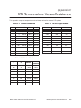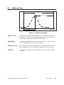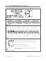
1
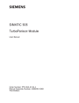
SIMATIC TI505 RTD Input Module User Manual Order Number: PPX:505–8114–2 Manual Assembly Number: 2586546–0059 Second Edition Copyright 1992 by Siemens Industrial Automation, Inc. All Rights Reserved — Printed in USA Reproduction, transmission or use of this document or contents is not permitted without express consent of Siemens Industrial Automation, Inc. All rights, including rights created by patent grant or registration of a utility model or design, are reserved. Since Siemens Industrial Automation, Inc. does not possess full access to data concerning all of the uses and applications of customer’s products, we do not assume responsibility either for customer product design or for any infringements of patents or rights of others which may result from our assistance. 01/21/92 Technical data is subject to change. We check the contents of every manual for accuracy at the time it is approved for printing; however, there may be undetected errors. Any errors found will be corrected in subsequent editions. Any suggestions for improvement are welcomed. MANUAL PUBLICATION HISTORY SIMATIC TI505 RTD Input Module User Manual Order Manual Number: PPX:505–8114-2 Refer to this history in all correspondence and/or discussion about this manual. Event Date Description Original Issue Second Edition 10/91 12/92 Original Issue (2592639–0001) Second Edition (2592639–0002) LIST OF EFFECTIVE PAGES Pages Cover/Copyright History/Effective Pages iii — viii 1-1 — 1-4 2-1 — 2-8 3-1 — 3-3 4-1 — 4-6 A-1 B-1 C-1 D-1 — D-5 Registration Description Second Second Second Second Second Second Second Second Second Second Second Second Pages Description Contents Preface Chapter 1 1.1 Product Overview Introduction . . . . . . . . . . . . . . . . . . . . . . . . . . . . . . . . . . . . . . . . . . . . . . . . . . . . . . . . . . . . . . . . . . . . 1-2 Measuring Temperature with Resistance . . . . . . . . . . . . . . . . . . . . . . . . . . . . . . . . . . . . . . . . . Series 505 RTD Input Module . . . . . . . . . . . . . . . . . . . . . . . . . . . . . . . . . . . . . . . . . . . . . . . . . . . . . 1-2 1-2 1.2 Features and Performance Specifications . . . . . . . . . . . . . . . . . . . . . . . . . . . . . . . . . . . . . . . . 1-3 1.3 How to Set Up the RTD Module for the Best Performance . . . . . . . . . . . . . . . . . . . . . . . . . . . 1-4 Choosing the Best RTD Type . . . . . . . . . . . . . . . . . . . . . . . . . . . . . . . . . . . . . . . . . . . . . . . . . . . . . Source-to-Return Resistance Affects Typical Accuracy . . . . . . . . . . . . . . . . . . . . . . . . . . . . Achieving Maximum Accuracy and Repeatability . . . . . . . . . . . . . . . . . . . . . . . . . . . . . . . . Handling Unused Inputs . . . . . . . . . . . . . . . . . . . . . . . . . . . . . . . . . . . . . . . . . . . . . . . . . . . . . . . . . Using RLL to Get Readings of Better Repeatability . . . . . . . . . . . . . . . . . . . . . . . . . . . . . . . . . 1-4 1-4 1-4 1-4 1-4 Chapter 2 2.1 2.2 2.3 2.4 Setting Options . . . . . . . . . . . . . . . . . . . . . . . . . . . . . . . . . . . . . . . . . . . . . . . . . . . . . . . . . . . . . . . . . 2-2 Overview . . . . . . . . . . . . . . . . . . . . . . . . . . . . . . . . . . . . . . . . . . . . . . . . . . . . . . . . . . . . . . . . . . . . . . . Integer Data Format . . . . . . . . . . . . . . . . . . . . . . . . . . . . . . . . . . . . . . . . . . . . . . . . . . . . . . . . . . . . Guidelines for Selecting Error Format . . . . . . . . . . . . . . . . . . . . . . . . . . . . . . . . . . . . . . . . . . . . . 2-2 2-3 2-3 Field Wiring . . . . . . . . . . . . . . . . . . . . . . . . . . . . . . . . . . . . . . . . . . . . . . . . . . . . . . . . . . . . . . . . . . . . . 2-4 Avoiding Noise . . . . . . . . . . . . . . . . . . . . . . . . . . . . . . . . . . . . . . . . . . . . . . . . . . . . . . . . . . . . . . . . . Power Requirements . . . . . . . . . . . . . . . . . . . . . . . . . . . . . . . . . . . . . . . . . . . . . . . . . . . . . . . . . . . . 2-4 2-4 Wiring for Two-, Three- and Four-wire Applications . . . . . . . . . . . . . . . . . . . . . . . . . . . . . . . . 2-6 RTD Excitation . . . . . . . . . . . . . . . . . . . . . . . . . . . . . . . . . . . . . . . . . . . . . . . . . . . . . . . . . . . . . . . . . . Using Four-wire RTDs . . . . . . . . . . . . . . . . . . . . . . . . . . . . . . . . . . . . . . . . . . . . . . . . . . . . . . . . . . . . . Using Three-wire RTDs . . . . . . . . . . . . . . . . . . . . . . . . . . . . . . . . . . . . . . . . . . . . . . . . . . . . . . . . . . . Using Two-wire RTDs . . . . . . . . . . . . . . . . . . . . . . . . . . . . . . . . . . . . . . . . . . . . . . . . . . . . . . . . . . . . . Using Intrinsic Safety Barriers . . . . . . . . . . . . . . . . . . . . . . . . . . . . . . . . . . . . . . . . . . . . . . . . . . . . . 2-6 2-6 2-6 2-7 2-7 Inserting the Module into the Base . . . . . . . . . . . . . . . . . . . . . . . . . . . . . . . . . . . . . . . . . . . . . . . 2-8 Choosing a Slot . . . . . . . . . . . . . . . . . . . . . . . . . . . . . . . . . . . . . . . . . . . . . . . . . . . . . . . . . . . . . . . . . Checking Status Indicator . . . . . . . . . . . . . . . . . . . . . . . . . . . . . . . . . . . . . . . . . . . . . . . . . . . . . . . 2-8 2-8 Chapter 3 3.1 3.2 Installing the Module Programming and Assigning I/O Points Programming the Controller . . . . . . . . . . . . . . . . . . . . . . . . . . . . . . . . . . . . . . . . . . . . . . . . . . . . . 3-2 WXs . . . . . . . . . . . . . . . . . . . . . . . . . . . . . . . . . . . . . . . . . . . . . . . . . . . . . . . . . . . . . . . . . . . . . . . . . . . . Word Format . . . . . . . . . . . . . . . . . . . . . . . . . . . . . . . . . . . . . . . . . . . . . . . . . . . . . . . . . . . . . . . . . . . 3-2 3-2 Logging the Module into the Controller . . . . . . . . . . . . . . . . . . . . . . . . . . . . . . . . . . . . . . . . . . . 3-3 Selecting the I/O Definition Chart . . . . . . . . . . . . . . . . . . . . . . . . . . . . . . . . . . . . . . . . . . . . . . . . Viewing the I/O Configuration Chart . . . . . . . . . . . . . . . . . . . . . . . . . . . . . . . . . . . . . . . . . . . . . 3-3 3-3 Contents iii Chapter 4 Troubleshooting and Maintenance 4.1 Symptoms and Corrective Actions . . . . . . . . . . . . . . . . . . . . . . . . . . . . . . . . . . . . . . . . . . . . . . . 4-2 4.2 Messages and Error Codes . . . . . . . . . . . . . . . . . . . . . . . . . . . . . . . . . . . . . . . . . . . . . . . . . . . . . . 4-3 4.3 Calibrating the Module . . . . . . . . . . . . . . . . . . . . . . . . . . . . . . . . . . . . . . . . . . . . . . . . . . . . . . . . . . 4-4 How Often to Calibrate the Module . . . . . . . . . . . . . . . . . . . . . . . . . . . . . . . . . . . . . . . . . . . . . Drift . . . . . . . . . . . . . . . . . . . . . . . . . . . . . . . . . . . . . . . . . . . . . . . . . . . . . . . . . . . . . . . . . . . . . . . . . . . . Recommended Equipment . . . . . . . . . . . . . . . . . . . . . . . . . . . . . . . . . . . . . . . . . . . . . . . . . . . . . Calibration Procedure . . . . . . . . . . . . . . . . . . . . . . . . . . . . . . . . . . . . . . . . . . . . . . . . . . . . . . . . . . 4-4 4-4 4-4 4-5 Calibration Troubleshooting . . . . . . . . . . . . . . . . . . . . . . . . . . . . . . . . . . . . . . . . . . . . . . . . . . . . . 4-6 4.4 Appendix A Typical Values for Common RTDs . . . . . . . . . . . . . . . . . . . . . . . . . A-1 Appendix B Typical Accuracy Versus Input Ohms. . . . . . . . . . . . . . . . . . . . . . B-1 Appendix C RTD Temperature Versus Resistance . . . . . . . . . . . . . . . . . . . . . . . C-1 Appendix D Specifications D.1 Physical and Environmental Specifications . . . . . . . . . . . . . . . . . . . . . . . . . . . . . . . . . . . . . . . D-2 D.2 Definition of Terms . . . . . . . . . . . . . . . . . . . . . . . . . . . . . . . . . . . . . . . . . . . . . . . . . . . . . . . . . . . . . . D-3 Mean Accuracy . . . . . . . . . . . . . . . . . . . . . . . . . . . . . . . . . . . . . . . . . . . . . . . . . . . . . . . . . . . . . . . . Repeatability . . . . . . . . . . . . . . . . . . . . . . . . . . . . . . . . . . . . . . . . . . . . . . . . . . . . . . . . . . . . . . . . . . . Absolute Accuracy . . . . . . . . . . . . . . . . . . . . . . . . . . . . . . . . . . . . . . . . . . . . . . . . . . . . . . . . . . . . . Resolution . . . . . . . . . . . . . . . . . . . . . . . . . . . . . . . . . . . . . . . . . . . . . . . . . . . . . . . . . . . . . . . . . . . . . . D-3 D-3 D-3 D-3 D.3 Series 505 RTD Input Module Quick Reference . . . . . . . . . . . . . . . . . . . . . . . . . . . . . . . . . . . . D-4 iv Contents List of Figures 1-1 Series 505 RTD Input Module . . . . . . . . . . . . . . . . . . . . . . . . . . . . . . . . . . . . . . . . . . . . . . . . . . . . . 1-2 2-1 2-2 2-3 2-4 2-5 2-6 2-7 Dipswitch Locations . . . . . . . . . . . . . . . . . . . . . . . . . . . . . . . . . . . . . . . . . . . . . . . . . . . . . . . . . . . . . Dipswitch Setting Diagram . . . . . . . . . . . . . . . . . . . . . . . . . . . . . . . . . . . . . . . . . . . . . . . . . . . . . . Integer Data Format . . . . . . . . . . . . . . . . . . . . . . . . . . . . . . . . . . . . . . . . . . . . . . . . . . . . . . . . . . . . Terminal Blocks and Pinouts . . . . . . . . . . . . . . . . . . . . . . . . . . . . . . . . . . . . . . . . . . . . . . . . . . . . . Wire Gauge and Stud Sizes . . . . . . . . . . . . . . . . . . . . . . . . . . . . . . . . . . . . . . . . . . . . . . . . . . . . . . RTD Sensor Wiring Diagrams . . . . . . . . . . . . . . . . . . . . . . . . . . . . . . . . . . . . . . . . . . . . . . . . . . . . . Inserting the Module into the Base . . . . . . . . . . . . . . . . . . . . . . . . . . . . . . . . . . . . . . . . . . . . . . . 2-2 2-3 2-3 2-5 2-5 2-7 2-8 3-1 3-2 3-3 Word Format . . . . . . . . . . . . . . . . . . . . . . . . . . . . . . . . . . . . . . . . . . . . . . . . . . . . . . . . . . . . . . . . . . . Sample I/O Definition Chart . . . . . . . . . . . . . . . . . . . . . . . . . . . . . . . . . . . . . . . . . . . . . . . . . . . . . I/O Configuration Chart . . . . . . . . . . . . . . . . . . . . . . . . . . . . . . . . . . . . . . . . . . . . . . . . . . . . . . . . . 3-2 3-3 3-3 4-1 Calibration Connector Wiring . . . . . . . . . . . . . . . . . . . . . . . . . . . . . . . . . . . . . . . . . . . . . . . . . . . . 4-5 B-1 Typical Accuracy Versus Input Ohms . . . . . . . . . . . . . . . . . . . . . . . . . . . . . . . . . . . . . . . . . . . . . B-1 D-1 Distribution of Readings . . . . . . . . . . . . . . . . . . . . . . . . . . . . . . . . . . . . . . . . . . . . . . . . . . . . . . . . . D-3 Contents v List of Tables 1-1 1-2 1-3 Features . . . . . . . . . . . . . . . . . . . . . . . . . . . . . . . . . . . . . . . . . . . . . . . . . . . . . . . . . . . . . . . . . . . . . . . . Probe Temperature Ranges . . . . . . . . . . . . . . . . . . . . . . . . . . . . . . . . . . . . . . . . . . . . . . . . . . . . . Performance Specifications . . . . . . . . . . . . . . . . . . . . . . . . . . . . . . . . . . . . . . . . . . . . . . . . . . . . . 1-3 1-3 1-3 2-1 Switch Assignments . . . . . . . . . . . . . . . . . . . . . . . . . . . . . . . . . . . . . . . . . . . . . . . . . . . . . . . . . . . . . 2-2 3-1 WXs . . . . . . . . . . . . . . . . . . . . . . . . . . . . . . . . . . . . . . . . . . . . . . . . . . . . . . . . . . . . . . . . . . . . . . . . . . . . 3-2 4-1 4-2 4-3 4-4 4-5 Symptoms and Corrective Actions . . . . . . . . . . . . . . . . . . . . . . . . . . . . . . . . . . . . . . . . . . . . . . . Messages and Error Codes in Controller Memory . . . . . . . . . . . . . . . . . . . . . . . . . . . . . . . . . Module Mean Accuracy Drift per Year Without Calibration . . . . . . . . . . . . . . . . . . . . . . . . Precision Resistor Values . . . . . . . . . . . . . . . . . . . . . . . . . . . . . . . . . . . . . . . . . . . . . . . . . . . . . . . . . Calibration Controller Input Values . . . . . . . . . . . . . . . . . . . . . . . . . . . . . . . . . . . . . . . . . . . . . . . 4-2 4-3 4-4 4-4 4-6 A-1 A-2 A-3 100-ohm Platinum . . . . . . . . . . . . . . . . . . . . . . . . . . . . . . . . . . . . . . . . . . . . . . . . . . . . . . . . . . . . . . 10-ohm Copper . . . . . . . . . . . . . . . . . . . . . . . . . . . . . . . . . . . . . . . . . . . . . . . . . . . . . . . . . . . . . . . . 120-ohm Nickel . . . . . . . . . . . . . . . . . . . . . . . . . . . . . . . . . . . . . . . . . . . . . . . . . . . . . . . . . . . . . . . . . A-1 A-1 A-1 C-1 C-2 C-3 Platinum 0.003850 DIN . . . . . . . . . . . . . . . . . . . . . . . . . . . . . . . . . . . . . . . . . . . . . . . . . . . . . . . . . . . 120-ohm Nickel . . . . . . . . . . . . . . . . . . . . . . . . . . . . . . . . . . . . . . . . . . . . . . . . . . . . . . . . . . . . . . . . . 10-ohm Copper 0.004274 . . . . . . . . . . . . . . . . . . . . . . . . . . . . . . . . . . . . . . . . . . . . . . . . . . . . . . . C-1 C-1 C-1 vi Contents Preface This manual describes the Series 505 Resistance Temperature Detector (RTD) Input Module (PPX:505–7038). Other Manuals Agency Approvals Refer to the manuals listed below for instructions on installing, programming, and troubleshooting your controller and I/O. • SIMATIC TI545 System Manual • SIMATIC TI560T/TI565T System Manual • SIMATIC TI505 Programming Reference Manual • SIMATIC TI500/TI505 TISOFT Release 4.2 User Manual • TISOFT 1 and 2, Rel. 2.0 User Manual This module meets the standards of the following agencies: • Underwriters Laboratories: UL Listed (Industrial Control Equipment) • Canadian Standards Association: CSA Certified (Process Control Equipment) • Factory Mutual Approved; Class I, Div. 2 Hazardous Locations • Verband Deutscher Elektrotechniker (VDE) 0160 Clearance/Creepage for Electrical Equipment (Self-Compliance) Series 505 products have been developed with consideration of the draft standard of the International Electrotechnical Commission Committee proposed standard (IEC-65A/WG6) for programmable controllers. Technical Assistance If you need information that is not included in this manual, or if you have problems using the Series 505 RTD Input Module, contact your Siemens Industrial Automation, Inc. distributor or sales office. If you need assistance in contacting your distributor or sales office in the United States, call 1–800–964-4114. SIMATIC TI505 RTD Input Module User Manual Preface vii Handling the Module Many integrated circuit (IC) devices are susceptible to damage by the discharge of static electricity. Follow the suggestions listed below to reduce the probability of damage to these devices when you handle a controller, a base controller, or any of the I/O modules. Both the module and the person who handles the module should be at the same ground potential. To accomplish this, fulfill the following conditions. Visual Inspection viii Preface • Transport the module in an anti-static container or anti-static material. • Ensure that the work area has a conductive pad with a lead that connects it to a common ground. • Ground yourself. Make contact with the conductive pad or wear a grounded wrist strap. If there is any visible damage to the module, contact your vendor for replacement. Simatic TI505 RTD Input Module User Manual Chapter 1 Product Overview 1.1 Introduction . . . . . . . . . . . . . . . . . . . . . . . . . . . . . . . . . . . . . . . . . . . . . . . . . . . . . . . . . . . . . . . . . . . . 1-2 Measuring Temperature with Resistance . . . . . . . . . . . . . . . . . . . . . . . . . . . . . . . . . . . . . . . . . Series 505 RTD Input Module . . . . . . . . . . . . . . . . . . . . . . . . . . . . . . . . . . . . . . . . . . . . . . . . . . . . . 1-2 1-2 1.2 Features and Performance Specifications . . . . . . . . . . . . . . . . . . . . . . . . . . . . . . . . . . . . . . . . 1-3 1.3 How to Set Up the RTD Module for the Best Performance . . . . . . . . . . . . . . . . . . . . . . . . . . . 1-4 Choosing the Best RTD Type . . . . . . . . . . . . . . . . . . . . . . . . . . . . . . . . . . . . . . . . . . . . . . . . . . . . . Source-to-Return Resistance Affects Typical Accuracy . . . . . . . . . . . . . . . . . . . . . . . . . . . . Achieving Maximum Accuracy and Repeatability . . . . . . . . . . . . . . . . . . . . . . . . . . . . . . . . Handling Unused Inputs . . . . . . . . . . . . . . . . . . . . . . . . . . . . . . . . . . . . . . . . . . . . . . . . . . . . . . . . . Using RLL to Get Readings of Better Repeatability . . . . . . . . . . . . . . . . . . . . . . . . . . . . . . . . . 1-4 1-4 1-4 1-4 1-4 SIMATIC TI505 RTD Input Module User Manual Product Overview 1-1 1.1 Introduction Measuring Temperature with Resistance A resistance thermometer consists of a resistance-temperature detector probe (RTD) and a resistance-measuring instrument (an RTD module). RTDs are passive transducers that function on the principle that the resistance of a pure metal is proportional to its temperature. An RTD probe consists of a wire of constant cross-section and known length, which is wound around a core of insulating material and enclosed in a protective housing. The probe-type RTD is usually stem-sensitive; that is, it must be immersed sufficiently to affect the full length of RTD wire wound around the core. Other types of probes available include the miniature tip-sensitive types for access to tight areas, thin film types for quicker-sensing, and washer-shaped types for easy-mounting surface-temperature measurement. The Series 505 RTD Input module pulses a small amount of current through the RTDs attached to it. The module measures the voltage generated by the current through the RTDs and then determines the resistance. Series 505 RTD Input Module The RTD Input module (see Figure 1-1) provides eight RTD inputs in a single-wide, Series 505 format. It is compatible with two-, three-, and four-wire RTDs, with automatic lead wire resistance compensation for three-wire and four-wire RTDs. RTD MOD GOOD 505–7038 I002765 Figure 1-1 Series 505 RTD Input Module 1-2 Product Overview SIMATIC 505 RTD Input Module User Manual 1.2 Features and Performance Specifications Table 1-1 Features Inputs Form factor RTD compatibility 8 Single-wide Platinum (4 types); copper; nickel (2 types); 2-, 3-, or 4-wire RTDs RTD zero degree ohms Configurable for eight different values Input data format to the controller Refer to Table 1-2 for probe ranges °F × 10 °C × 10 Ω × 10 (1.0 to 2000.0) Ω × 100 (1.00 to 320.00) Scaled counts, 0 to 32000 External power Error reporting Input noise filtering None required Configurable for separate error words or upscale error codes Module automatically detects open, shorted, or out-of-range inputs Configurable for 50/60 Hz rejection Internal resolution 0.003 Ω (19-bit) Lead wire compensation 500 Ω max (<50 Ω recommended) Table 1-2 Probe Temperature Ranges Platinum Copper Nickel °F × 10 –328.0 to 1562.0 –328.0 to 500.0 –112.0 to 527.0 °C × 10 –200.0 to 850.0 –200.0 to 260.0 –80.0 to 275.0 Table 1-3 Performance Specifications Typical 20–30°C / 68–86°F Specification Limit 0 to 60°C / 32 to 140°F Mean accuracy (100 Ω platinum RTD) 0.1°C 0.2°F 0.03 Ω 0.6°C 1.2°F 0.25 Ω Repeatability (100 Ω platinum RTD) 0.1°C 0.2°F 0.03 Ω 0.3°C 0.5°F 0.11 Ω 0.2°C 0.4°F 0.9°C 1.7°F Absolute accuracy 100 Ω platinum Ω × 100 0.06 Ω 0.36 Ω Ω × 10 0.1 Ω + 0.05% of input Ω 0.1 Ω + 0.2% of input Ω Common-mode rejection 100 dB — Normal-mode rejection at line frequency ±0.01 Hz 80 dB — Normal-mode rejection at line frequency ±3 Hz 25 dB — Update time per active input: all inputs <470 Ω <110 ms @ 60 Hz filter <120 ms @ 50 Hz filter Step response time: 100 Ω platinum RTD 250 ms × number of active inputs Step response time: inputs to 2 kΩ 625 ms × number of active inputs Base power +5 V 2.2 W max, 1.6 W typical –5 V 0W Isolation (inputs to controller) SIMATIC TI505 RTD Input Module User Manual 1500 Vrms Product Overview 1-3 1.3 How to Set Up the RTD Module for the Best Performance Choosing the Best RTD Type The Series 505 RTD module has been optimized for the 100 Ω platinum RTD positive temperature range of 100 to 400 Ω. Mean accuracy and repeatability is best in this range. Source-to-Return Resistance Affects Typical Accuracy This module operates with source-to-return resistance from 1 to 2000 Ω. Typical accuracy is better than 0.03% of the reading from 50 to 2000 Ω. Below 50 Ω, absolute accuracy typically is better than 0.02 Ω. Achieving Maximum Accuracy and Repeatability Follow these guidelines to achieve maximum accuracy and repeatability: • For low-temperature operation, choose an RTD with a higher 0°C resistance. Maximum accuracy occurs when the expected RTD operating range resistance falls between 100 and 400 Ω. See Appendix C for some common RTDs and their temperature/resistance values. • Use platinum RTD probes. Platinum is the most stable material commonly used for RTDs; its initial and long-term accuracy are best. • RTD probes can have self-heating effects. The RTD module uses very little current to excite the RTD element; however, in some situations, poor sensor thermal conductivity can cause temperature offset. The module pulses a current with a duty cycle less than 12.5%. This current source is nominally 2.5 mA when the source-to-return resistance is less than 500 Ω and 1 mA for source-to-return resistance greater than 500 Ω. • To choose an RTD probe to fit the measurement task, refer to the RTD manufacturer’s recommendations. • Use low 0°C Ω (10 Ω copper) RTDs only when your required measurement accuracy is 2°C or more. • Use two-wire connectivity only when your required measurement accuracy is greater than the offset that is generated by the lead wire resistance. • Four-wire connectivity is best for accuracy and repeatability. Handling Unused Inputs Leave unused inputs unconnected for fastest response. Using RLL to Get Readings of Better Repeatability If your application requires absolute accuracy greater than that specified for this module, you can minimize the effect of repeatability error by writing a program in RLL to take the average of readings over a period of time. However, this occurs at the expense of update time. 1-4 Product Overview SIMATIC 505 RTD Input Module User Manual Chapter 2 Installing the Module 2.1 2.2 2.3 2.4 Setting Options . . . . . . . . . . . . . . . . . . . . . . . . . . . . . . . . . . . . . . . . . . . . . . . . . . . . . . . . . . . . . . . . . 2-2 Overview . . . . . . . . . . . . . . . . . . . . . . . . . . . . . . . . . . . . . . . . . . . . . . . . . . . . . . . . . . . . . . . . . . . . . . . Integer Data Format . . . . . . . . . . . . . . . . . . . . . . . . . . . . . . . . . . . . . . . . . . . . . . . . . . . . . . . . . . . . Guidelines for Selecting Error Format . . . . . . . . . . . . . . . . . . . . . . . . . . . . . . . . . . . . . . . . . . . . . 2-2 2-3 2-3 Field Wiring . . . . . . . . . . . . . . . . . . . . . . . . . . . . . . . . . . . . . . . . . . . . . . . . . . . . . . . . . . . . . . . . . . . . . 2-4 Avoiding Noise . . . . . . . . . . . . . . . . . . . . . . . . . . . . . . . . . . . . . . . . . . . . . . . . . . . . . . . . . . . . . . . . . Power Requirements . . . . . . . . . . . . . . . . . . . . . . . . . . . . . . . . . . . . . . . . . . . . . . . . . . . . . . . . . . . . 2-4 2-4 Wiring for Two-, Three- and Four-wire Applications . . . . . . . . . . . . . . . . . . . . . . . . . . . . . . . . 2-6 RTD Excitation . . . . . . . . . . . . . . . . . . . . . . . . . . . . . . . . . . . . . . . . . . . . . . . . . . . . . . . . . . . . . . . . . . Using Four-wire RTDs . . . . . . . . . . . . . . . . . . . . . . . . . . . . . . . . . . . . . . . . . . . . . . . . . . . . . . . . . . . . . Using Three-wire RTDs . . . . . . . . . . . . . . . . . . . . . . . . . . . . . . . . . . . . . . . . . . . . . . . . . . . . . . . . . . . Using Two-wire RTDs . . . . . . . . . . . . . . . . . . . . . . . . . . . . . . . . . . . . . . . . . . . . . . . . . . . . . . . . . . . . . Using Intrinsic Safety Barriers . . . . . . . . . . . . . . . . . . . . . . . . . . . . . . . . . . . . . . . . . . . . . . . . . . . . . 2-6 2-6 2-6 2-7 2-7 Inserting the Module into the Base . . . . . . . . . . . . . . . . . . . . . . . . . . . . . . . . . . . . . . . . . . . . . . . 2-8 Choosing a Slot . . . . . . . . . . . . . . . . . . . . . . . . . . . . . . . . . . . . . . . . . . . . . . . . . . . . . . . . . . . . . . . . . Checking Status Indicator . . . . . . . . . . . . . . . . . . . . . . . . . . . . . . . . . . . . . . . . . . . . . . . . . . . . . . . 2-8 2-8 SIMATIC TI505 RTD Input Module User Manual Installing the Module 2-1 2.1 Setting Options Overview Figure 2-1 shows the dipswitch locations. Avoid setting dipswitches with a pencil, as graphite can damage the switch assembly. Table 2-1 lists the features and options, and Figure 2-2 shows the option settings. Dipswitches S1 S2 Dipswitch setting diagram I002766 Figure 2-1 Dipswitch Locations Table 2-1 Switch Assignments Feature Options Assembly Switches Default Input resistance at 0°C One of eight values for input resistance at 0°C. Also selects the reporting scale for direct Ω input. S1 1, 2, and 3 100 Ω Probe type One of 7 RTD curves. S1 4, 5, and 6 Pt 0.003850 DIN WX input format °F × 10 °C × 10 ohms × 10 ohms × 100 scaled integer. S1 7 and 8 °F × 10 Lead resistance compensation 2-, 3-, or 4-wire. S2 1 3-wire Error format 16WX/separate error words or 8WX/upscale errors (32752 and above). S2 2 16WX Input filtering 50 or 60 Hz. S2 3 60 Hz Calibration Run or calibration mode. S2 8 Run NOTE: You must use 8WX error format with a SIMATIC TI525, SIMATIC TI530, or SIMATIC TI530C. 2-2 Installing the Module SIMATIC 505 RTD Input Module User Manual Run Cal I002767 Figure 2-2 Dipswitch Setting Diagram Integer Data Format Refer to Table 2-1 for data format options. Figure 2-3 shows how the integer format works in an RTD application when a platinum probe is registering 325.0°C (mid-range). In general terms, temp min temp actual max temp min temp scaled integer 32000 32000 Probe type Min temp Max temp Platinum –200°C 850°C Copper –200°C 260°C Nickel –80°C 275°C 24000 16000 8000 325 WX 0 –200 –50 100 250 400 550 700 850 Min temp Max temp WX 32000 (t ( 200.0)) 16000 (850.0 ( 200.0)) I002768 Figure 2-3 Integer Data Format Guidelines for Selecting Error Format The difference between 8WX and 16WX input formats consists primarily of how the module behaves when an error occurs. You must use 8WX format with a TI525, TI530, or TI530C. If the module is set for 8WX and an error occurs, the input data are replaced by an error word and that input ceases updating. You must correct the error condition before the input resumes updating. If the module is set for 16WX inputs and an error occurs, the last valid data are frozen. An error word is reported in one of the last eight inputs as shown in Table 3-1. This allows the error to be detected in your application program without immediately affecting controller operation. SIMATIC TI505 RTD Input Module User Manual Installing the Module 2-3 2.2 Field Wiring ! WARNING Use wires suitable for at least 75° C. Signal wiring connected to this module must be rated at least 300 V. ! ATTENTION Employer des fils d’alimentation pour au moins 75° C. Le cablage de signalisation raccorde dans cette boite doit convenir pour une tension nominale d’au moins 300 V. Avoiding Noise Power Requirements 2-4 To avoid noise problems, follow these guidelines when you install the module. • Use the shortest possible wires. • Select 50/60 Hz filtering to match the local AC power line frequency. • Do not install the module adjacent to power-switching modules. • Avoid placing signal wires parallel to high-energy wires. If the two must meet, cross them at right angles. • Avoid bending the wire into sharp angles. • Use wireways for wire routing. • Use a four-wire conductor with a shield, and tie the shield to ground potential. • Terminate shields at RTD sensor location to earth ground. • Place wires so that they do not interfere with existing wiring. • Never terminate the shield at both the RTD sensor and the module connector. The module consumes a maximum of 2.2 W of +5 V and no –5 V power from the base. No external power supply is required. Installing the Module SIMATIC 505 RTD Input Module User Manual RTD2 sense– RTD1 sense– RTD2 return RTD1 return RTD2 sense+ RTD1 sense+ RTD2 source RTD1 source shield shield RTD4 sense– RTD3 sense– RTD4 return RTD3 return RTD4 sense+ RTD3 sense+ RTD4 source RTD3 source shield shield RTD6 sense– RTD5 sense– RTD6 return RTD5 return RTD6 sense+ RTD5 sense+ RTD6 source RTD5 source shield shield RTD8 sense– RTD7 sense– RTD8 return PPX:2587705–8002 Order separately Wiring diagram PPX:2587705–8006 Shipped with module RTD7 return RTD8 sense+ RTD7 sense+ RTD8 source RTD7 source shield shield I002769 Figure 2-4 Terminal Blocks and Pinouts Stud Size: #4 (2.5mm) Stud Size: #4 (2.5mm) Amp Part#: 321462. Use with connector PPX:2587705–8002. Amp Part#: 327891. Use with connector PPX:2587705–8002. (Specify 2pt. Connector) Max. Width: 5.54 mm (.218 in.) Max. Width: 4.62 mm (.182 in.) Wire Gauge: 14–24 (both connectors) 1 cm (0.25 in.) I002770 Figure 2-5 Wire Gauge and Stud Sizes SIMATIC TI505 RTD Input Module User Manual Installing the Module 2-5 2.3 Wiring for Two-, Three- and Four-wire Applications In general, you can use three-or four-wire twisted shielded, cable (14–24 AWG or 0.18–1.5mm2, either stranded or solid-type). All eight channels have a common return. To provide isolation, use isolated sensors. In addition, it is good practice to label all wires. Figure 2-6 shows wiring diagrams for all three wiring configurations. RTD Excitation The module pulses a current with a duty cycle less than 12.5%. This current source is nominally 2.5 mA when the source-to-return resistance is less than 500 Ω and 1 mA for source-to-return resistance greater than 500 Ω. To meet accuracy specifications, connect each RTD to one module input only. Use dual-element RTDs if you require redundant temperature measurement. Using Four-wire RTDs Using Three-wire RTDs 2-6 Four-wire RTDs provide the best accuracy. Changes in contact, wire, or terminal impedance can affect the accuracy of three-wire RTD readings, where four-wire RTDs are not affected. Refer to the following guidelines: • Use four-wire shielded cable. • The module has been optimized for source-to-return resistances of 400 Ω or less. For maximum accuracy, keep the RTD and wire impedances within this range. The maximum allowable source-to-return resistance is 2 kΩ. • Wire impedance is relatively unimportant for Sense+ and Sense– wires; it must be ≤2 kΩ from the Sense lines to Return. • Wire type and temperature coefficient do not affect accuracy for four-wire RTD applications. Four-wire RTDs provide the best performance. However, if your application requires three-wire RTDs, consider the following guidelines: • Connect one side of the RTD to Sense+ and Source, and connect the other side to Return. • Try to achieve equal resistance between the Source and Return wires. Any difference in resistance between these two wires is registered as offset. • If necessary, you can use shielded, twisted pair cable, but the twisted pair must go to Return and Source, and shield must go to Sense+. In this case, the shield is used as a conductor, not a shield, and noise may be a problem. Installing the Module SIMATIC 505 RTD Input Module User Manual • For better accuracy, limit each lead wire resistance to below 50 Ω and ensure that the temperature coefficient of the Source and Return wires is the same. • The module can accommodate up to 500 Ω lead resistance. • Contact resistances can become significant for three-wire measurements; the module cannot compensate for these resistances. Using Two-wire RTDs Run three or four wires from the RTD probe to the module. If you can run only two wires from the RTD probe to the module and accuracy is relatively unimportant, connect a jumper between Sense– and Return and another between Sense+ and Source at the module connector; be sure to set the module dipswitches for four-wire operation. Refer to Figure 2-6. Run two-wire, twisted/shielded pair cable to the RTD. Depending on the wiring environment, lead resistance and lead wire temperature drift cause temperature offsets. The module cannot differentiate between wire and sensor resistance in two-wire mode. Using Intrinsic Safety Barriers If your application requires intrinsic safety barriers, be sure to use four-wire RTDs. Otherwise, the series resistance imbalance degrades accuracy. Also, select the barrier for minimal leakage current, as this can affect accuracy in three- or four-wire modes. NOTE: Normally, you must attach the shield only at the RTD location. If this is not possible, you can terminate the shield at the module. Never attach the shield at both the RTD location and the RTD module. Module Sense– N/C Module Sense– Sense– Return Return RTD Module RTD Earth ground N/C Return RTD Sense+ Sense+ Sense+ Source Source Source Shield Four-wire, lead compensation Earth ground N/C Shield Three-wire, lead compensation Earth ground N/C Shield Two-wire, no lead compensation— set module to four-wire mode I002771 Figure 2-6 RTD Sensor Wiring Diagrams SIMATIC TI505 RTD Input Module User Manual Installing the Module 2-7 2.4 ! Inserting the Module into the Base WARNING Choosing a Slot To minimize risk of potential shock hazard, turn off power to the I/O base and to any modules installed in the base before inserting or removing a module or installing a terminal block. Failure to do so may result in potential injury to personnel or damage to equipment. The RTD module fits into any available single I/O slot on any Series 505 base as shown in Figure 2-7. Avoid installing the module adjacent to high-energy switching modules or other potential sources of electromagnetic interference. Note the minimum torque required to provide grounding. Minimum torque: 2.6 in-lb (0.3N-m) Maximum torque: 4.12 in-lb (0.6N-m) Terminal block I002772 Figure 2-7 Inserting the Module into the Base Checking Status Indicator 2-8 Within 6 seconds of power-up, the LED on the bezel comes on, indicating that the module is good. If the LED fails to come on, refer to Chapter 4 for troubleshooting procedures. Installing the Module SIMATIC 505 RTD Input Module User Manual Chapter 3 Programming and Assigning I/O Points 3.1 3.2 Programming the Controller . . . . . . . . . . . . . . . . . . . . . . . . . . . . . . . . . . . . . . . . . . . . . . . . . . . . . 3-2 WXs . . . . . . . . . . . . . . . . . . . . . . . . . . . . . . . . . . . . . . . . . . . . . . . . . . . . . . . . . . . . . . . . . . . . . . . . . . . . Word Format . . . . . . . . . . . . . . . . . . . . . . . . . . . . . . . . . . . . . . . . . . . . . . . . . . . . . . . . . . . . . . . . . . . 3-2 3-2 Logging the Module into the Controller . . . . . . . . . . . . . . . . . . . . . . . . . . . . . . . . . . . . . . . . . . . 3-3 Selecting the I/O Definition Chart . . . . . . . . . . . . . . . . . . . . . . . . . . . . . . . . . . . . . . . . . . . . . . . . Viewing the I/O Configuration Chart . . . . . . . . . . . . . . . . . . . . . . . . . . . . . . . . . . . . . . . . . . . . . 3-3 3-3 SIMATIC TI505 RTD Input Module User Manual Programming and Assigning I/O Points 3-1 3.1 Programming the Controller Refer to your controller program design manual for specific details on designing a program. WXs Refer to Table 3-1 for the WX configuration. Table 3-1 WXs Word Format Format Inputs I/O Words Values WX16 8 WX 1–8 WX 9–16 Input points 1–8 Separate error words WX8 8 WX 1–8 Input points 1–8; upscale errors Words are signed, 16-bit numbers. Refer to Figure 3-1 for the word format. MSB LSB 1 2 3 4 5 6 7 8 9 10 11 12 13 14 15 16 0 0 0 0 0 0 0 0 0 0 0 0 0 0 0 0 sign bit 15 bits for process value Figure 3-1 Word Format 3-2 Programming and Assigning I/O Points SIMATIC 505 RTD Input Module User Manual 3.2 Logging the Module into the Controller Selecting the I/O Definition Chart Figure 3-2 shows a sample I/O definition chart with two modules installed in a four-slot base. Slot 1 holds a module configured for 16 WX; slot 2 holds a module configured for 8 WX. Refer to your TISOFT manual for detailed instructions. I/O Address The module is logged in as eight or 16 input words (WX). I/O MODULE DEFINITION FOR : I/O Slot Number Install the module into any available I/O slot in the Series 505 base. See Section 2.4. Slot Base Number Displays number of the current base. CHANNEL 1 BASE 00 Number of Bit and Word I/O Special Address X Y WX WY Function 1 ..... 0001 ..... 00 .. 00 .. 16 .. 00 ....... No 2 ..... 0017 ..... 00 .. 00 .. 08 .. 00 ....... No 3 ..... 0000 ..... 00 .. 00 .. 00 .. 00 ....... No 4 ..... 0000 ..... 00 .. 00 .. 00 .. 00 ....... No SF Module Series 505 RTD is not an SF Module. The default for this definition is no. I000725 Figure 3-2 Sample I/O Definition Chart Viewing the I/O Configuration Chart Use SHOW or a similar menu selection to display the I/O configuration chart. The configurations in Figure 3-2 appear as shown in Figure 3-3. Slot 1 holds a module configured for 16 WX; slot 2 holds a module configured for 8 WX. I/O CONFIGURATION CHART FOR CHANNEL . . . 1 BASE . . . . . 00 I/O POINTS SLOT 1 1 WX0001 2 WX0002 3 WX0003 4 WX0004 5 WX0005 6 WX0006 7 WX0007 8 WX0008 SLOT 1 9 WX0009 10 WX0010 11 WX0011 12 WX0012 13 WX0013 14 WX0014 15 WX0015 16 WX0016 SLOT 2 17 WX0017 18 WX0018 19 WX0019 20 WX0020 21 WX0021 22 WX0022 23 WX0023 24 WX0024 SLOT 3 SLOT 4 Figure 3-3 I/O Configuration Chart SIMATIC TI505 RTD Input Module User Manual Programming and Assigning I/O Points 3-3 Chapter 4 Troubleshooting and Maintenance 4.1 Symptoms and Corrective Actions . . . . . . . . . . . . . . . . . . . . . . . . . . . . . . . . . . . . . . . . . . . . . . . 4-2 4.2 Messages and Error Codes . . . . . . . . . . . . . . . . . . . . . . . . . . . . . . . . . . . . . . . . . . . . . . . . . . . . . . 4-3 4.3 Calibrating the Module . . . . . . . . . . . . . . . . . . . . . . . . . . . . . . . . . . . . . . . . . . . . . . . . . . . . . . . . . . 4-4 How Often to Calibrate the Module . . . . . . . . . . . . . . . . . . . . . . . . . . . . . . . . . . . . . . . . . . . . . Drift . . . . . . . . . . . . . . . . . . . . . . . . . . . . . . . . . . . . . . . . . . . . . . . . . . . . . . . . . . . . . . . . . . . . . . . . . . . . Recommended Equipment . . . . . . . . . . . . . . . . . . . . . . . . . . . . . . . . . . . . . . . . . . . . . . . . . . . . . Calibration Procedure . . . . . . . . . . . . . . . . . . . . . . . . . . . . . . . . . . . . . . . . . . . . . . . . . . . . . . . . . . 4-4 4-4 4-4 4-5 Calibration Troubleshooting . . . . . . . . . . . . . . . . . . . . . . . . . . . . . . . . . . . . . . . . . . . . . . . . . . . . . 4-6 4.4 SIMATIC TI505 RTD Input Module User Manual Troubleshooting and Maintenance 4-1 4.1 Symptoms and Corrective Actions If you need assistance with any of the problems or corrective actions listed below, call your Siemens Industrial Automation, Inc. distributor. Table 4-1 Symptoms and Corrective Actions Symptom Incorrect readings CPU nonfatal error on TISOFT screen 4-2 Troubleshooting and Maintenance Possible Cause Corrective Action Connections incorrect Trace wiring connections. Signal wire noise Use shielded wire; refer to Section 2.2. Module not configured Check I/O configuration. Unbalanced lead wires Refer to Section 2.3. Dipswitches set incorrectly Refer to Section 2.1. Module configured incorrectly Reconfigure the module. Module not seated in base Install correctly and reconfigure. Module failed Return the module for repair. SIMATIC 505 RTD Input Module User Manual 4.2 Messages and Error Codes Table 4-2 Messages and Error Codes in Controller Memory Signed Integer Hex Code Problem 32767 7FFF Failed module 32766 7FFE Input underrange RTD input is below expected range Check dipswitches. Check wiring, sensor. 32765 7FFD Input overrange RTD input is above expected range Check dipswitches. Check wiring, sensor. 32764 7FFC Source short Short from Source to Return Check wiring, sensor. 32763 7FFB Sense short Short from Sense+ to Return (3-wire) or from Sense+ to Sense– (4-wire) Check wiring, sensor. 32762 7FFA Input not wired All three inputs are open or improperly wired: Source, Sense+, and Sense– Wire module channel. 32761 7FF9 Source open Source to Return ≥3500 Ω Check Source wire. 32760 7FF8 Sense+ open Sense+ Resistance ≥2500 Ω Check Sense+ wire. 32759 7FF7 Sense– open Sense– Resistance ≥2500 Ω Check Sense– wire. 32758 7FF6 Source-to-Return overrange >2000 Ω from Source to Return Check wiring, sensor. 32757 7FF5 EEPROM fail Corrupt EEPROM calibration data Attempt to re-calibrate. Return for repair. 32756 7FF4 Cal out-of-range Calibration input on this channel is out-of-range Check calibration values. Refer to Section 4.3. 32755 7FF3 Cal complete Calibration is successful Return module to operation. 32754 7FF2 Not used 32753 7FF1 Not used 32752 7FF0 Not used 4 0004 Four-wire mode Module is correctly performing 4-wire conversions for this input (separate error words only) Module channel functioning properly 3 0003 Three-wire mode Module is correctly performing 3-wire conversions for this input (separate error words only) Module channel functioning properly 0 0000 No data Module not yet configured (separate error words only) Configure module. Description Corrective Action Module has set fail bit; MOD GOOD LED indicator goes off SIMATIC TI505 RTD Input Module User Manual Check dipswitches. Reseat module in base. Return for repair. Troubleshooting and Maintenance 4-3 4.3 Calibrating the Module How Often to Calibrate the Module Although the RTD module does not require calibration at installation, some applications may require periodic calibration. If you operate in an environment where the ambient temperature cycles outside the range of 20°C to 30°C, more frequent calibration may be required. Also, if the application environment is a constant temperature outside the 20°C to 30°C range, calibration at the application temperature may improve system accuracy. Drift Without calibration, expected mean accuracy drift per year is 0.05% of the ohms input value; this is equivalent to the following temperature values for common RTDs. Table 4-3 Module Mean Accuracy Drift per Year Without Calibration Measured Temperature Recommended Equipment 100-ohm Platinum 10-ohm Copper 120-ohm Nickel °C °F °C °F °C °F °C °F –200 –100 0 100 200 260 400 600 800 –328 –148 32 212 392 500 752 1112 1472 0.1 0.1 0.2 0.2 0.3 0.3 0.4 0.5 0.7 0.2 0.3 0.4 0.5 0.6 0.6 0.8 1.0 1.3 0.1 0.1 0.2 0.2 0.3 0.3 — — — 0.2 0.3 0.4 0.4 0.5 0.6 — — — — — 0.1 0.2 0.2 0.2 — — — — — 0.3 0.4 0.4 0.4 — — — Calibration requires a standard Series 505 I/O connector and four precision resistors. These resistors must meet or exceed the specifications outlined in Table 4-4. You can order a connector by contacting your Siemens Industrial Automation, Inc. distributor and asking for PPX:2587705–8009. Figure 4-1 shows how to assemble a calibration connector, using the precision resistors listed in Table 4-4. Table 4-4 Precision Resistor Values Ohms 4-4 Tolerance Temperature Coefficient 10 0.1% 25 ppm/°C 100 0.01% 10 ppm/°C 402 0.005% 10 ppm/°C 1600 0.01% 10 ppm/°C Troubleshooting and Maintenance SIMATIC 505 RTD Input Module User Manual Calibration Procedure Follow these steps to calibrate the module. No warmup period is required. 1. Remove power from the base containing the RTD module to be calibrated. 2. Remove the field wiring I/O connector from the RTD module. 3. Remove the RTD module from the base. 4. Set S2 dipswitch 8 to the Cal (0) position. 5. Install the precision resistors as shown in Figure 4-1. 6. Reinsert the RTD module into the base. 7. Apply power to the base. The module LED begins blinking slowly. After about 2 minutes, the LED begins blinking quickly, indicating that the calibration process is complete. 8. Reverse the steps and return the module to operation. Channel 1 10 ± 0.01 Ω Channel 3 402 ± 0.02 Ω Channel 2 100 ± 0.01 Ω Channel 4 1600 ± 0.16 Ω I/O connector (PPX:2587705–8009) with precision resistors installed Note: It is not necessary to connect inputs 5 through 8. I002773 Figure 4-1 Calibration Connector Wiring SIMATIC TI505 RTD Input Module User Manual Troubleshooting and Maintenance 4-5 4.4 Calibration Troubleshooting If the LED does not follow the pattern defined in the last step of Section 4.3, one or more of the calibration resistors may be out of range. Refer to the controller input values from the module. If the module is set for 16 WX, this information is available in module inputs 9–12; otherwise, these values appear in the first four module inputs. Table 4-5 shows the values. Table 4-5 Calibration Controller Input Values 4-6 Integer Hex Description 32757 7FF5 Calibration data in the module EEPROM are bad. Try to recalibrate the module. If unsuccessful, return for repair. 32756 7FF4 The calibration resistor on this channel is out of acceptable range. Verify with a 0.01% ohmmeter that this resistor is within the required tolerance. 32755 7FF3 Calibration has completed with no errors. Return module to operation. Troubleshooting and Maintenance SIMATIC 505 RTD Input Module User Manual Appendix A Typical Values for Common RTDs These values represent average expected performance of the Series 505 RTD module alone. System performance specifications also are affected by RTD performance and any wiring impedance mismatch or variability. Table A-1 100-ohm Platinum Format Range Mean Accuracy °F –328 to +1562 0.2 °C –200 to +850 Ω Integer Repeatability Absolute Accuracy Resolution 0.2 0.4 0.1 0.1 0.1 0.2 0.1 17 to 396 0.03 0.03 0.06 0.1 0 to 32000 5 5 10 1 Table A-2 10-ohm Copper Format Range Mean Accuracy °F –328 to +500 1.3 °C –200 to +260 0.7 Ω 1.1 to 21.2 Integer 0 to 32000 0.03 51 Repeatability Absolute Accuracy Resolution 1 2.3 0.1 0.5 1.2 0.1 0.05 0.01 0.02 37 88 1 Table A-3 120-ohm Nickel Format Range Mean Accuracy °F –112 to +527 0.2 °C –80 to +275 Ω 65 to 402 Integer 0 to 32000 Absolute Accuracy Resolution 0.2 0.4 0.1 0.1 0.1 0.2 0.1 0.03 0.03 0.06 0.1 10 SIMATIC TI505 RTD Input Module User Manual Repeatability 9 19 1 Typical Values for Common RTDs A-1 Appendix B Typical Accuracy Versus Input Ohms 0.6 0.60 Typical Accuracy (Ohms) 0.5 0.4 0.3 0.24 0.20 0.2 0.16 0.1 0.05 0.06 0.0 0 1Ω 200 400 Recommended wire + RTD impedance range 600 800 500 Ω 1000 1200 1400 1600 1800 2000 Input Ohms I002733 Figure B-1 Typical Accuracy Versus Input Ohms SIMATIC TI505 RTD Input Module User Manual Typical Accuracy Versus Input Ohms B-1 Appendix C RTD Temperature Versus Resistance This appendix compares temperature and resistance values for common RTD probes. Table C-1 Platinum 0.003850 DIN °F °C 100 Ω 200 Ω –328 –200 18.49 36.99 –148 –100 60.25 32 0 212 Table C-3 10-ohm Copper 0.004274 500 Ω °F °C 92.47 –328 –200 1.17 120.51 301.27 –238 –150 3.44 100.00 200.00 500.00 –148 –100 5.68 100 138.50 277.00 692.50 –58 –50 7.86 392 200 175.84 351.68 879.20 32 0 10.00 572 300 212.02 424.04 1060.09 122 50 12.14 752 400 247.04 494.08 1235.19 212 100 14.27 932 500 280.90 561.79 1404.48 302 150 16.41 1112 600 313.59 627.19 1567.97 392 200 18.57 1292 700 345.13 690.26 1725.66 482 250 20.73 1472 800 375.51 751.02 1877.55 500 260 21.16 1562 850 390.26 780.53 1951.31 Ohms Table C-2 120-ohm Nickel DIN 0.006178 °F °C –112 –80 66.60 72.59 –58 –50 86.16 89.11 32 0 120.00 120.00 122 50 157.75 154.93 212 100 200.64 194.14 302 150 248.95 238.39 392 200 303.45 288.95 482 250 366.53 347.57 527 275 401.69 380.60 0.006720 SIMATIC TI505 RTD Input Module User Manual RTD Temperature Versus Resistance C-1 Appendix D Specifications D.1 Physical and Environmental Specifications . . . . . . . . . . . . . . . . . . . . . . . . . . . . . . . . . . . . . . . D-2 D.2 Definition of Terms . . . . . . . . . . . . . . . . . . . . . . . . . . . . . . . . . . . . . . . . . . . . . . . . . . . . . . . . . . . . . . D-3 Mean Accuracy . . . . . . . . . . . . . . . . . . . . . . . . . . . . . . . . . . . . . . . . . . . . . . . . . . . . . . . . . . . . . . . . Repeatability . . . . . . . . . . . . . . . . . . . . . . . . . . . . . . . . . . . . . . . . . . . . . . . . . . . . . . . . . . . . . . . . . . . Absolute Accuracy . . . . . . . . . . . . . . . . . . . . . . . . . . . . . . . . . . . . . . . . . . . . . . . . . . . . . . . . . . . . . Resolution . . . . . . . . . . . . . . . . . . . . . . . . . . . . . . . . . . . . . . . . . . . . . . . . . . . . . . . . . . . . . . . . . . . . . . D-3 D-3 D-3 D-3 Series 505 RTD Input Module Quick Reference . . . . . . . . . . . . . . . . . . . . . . . . . . . . . . . . . . . . D-4 D.3 SIMATIC TI505 RTD Input Module User Manual Specifications D-1 D.1 Physical and Environmental Specifications Minimum torque for bezel screws 2.6 in-lb (0.3N-m) Maximum torque for bezel screws 4.12 in-lb (0.6N-m) Input signal wiring Shielded, twisted cable (12–26 AWG or 0.16–3.2 mm2, either stranded or solid-type) Spade lug for use with connector PPX:2587705–8002 Amp part number 321462 Ring lug for use with connector PPX:2587705–8002 Amp part number 327891 Module power required from base +5 V: 2.2 W max, 1.6 W typical –5 V: 0 W Operating temperature 0° to 60°C (32° to 140°F) Storage temperature –40° to +70°C (–40° to 158°F) Relative humidity 5% to 95% noncondensing Pollution degree 2, IEC 664, 664A Vibration Sinusoidal IEC 68-2-6, Test Fc 0.15 mm peak-to-peak, 10–57 Hz; 1.0 g, 57–150 Hz Random IEC 68-2-34, Test Fdc, equivalent to NAVMAT P–9492 0.04 g2/Hz, 80–350 Hz Electrostatic discharge IEC 801, Part 2, Level 4, (15 kV) Shock IEC 68-2-27; Test Ea Noise immunity, conducted IEC 801, Part 4, Level 3 MIL STD 461B CS01, CS02 and CS06; IEC 255–4 Appendix E EEC 4517/79 COM (78) 766 Final Part 4 Noise immunity, radiated IEC 801, Part 3, Level 3; MIL STD 461B RS01, and RS02 IEC 801, Part 4, Level 3 Isolation, inputs to controller 1500 Vrms Corrosion protection All parts of corrosion-resistant material or plated or painted as corrosion protection D-2 Specifications SIMATIC 505 RTD Input Module User Manual D.2 Definition of Terms Absolute accuracy Mean reading Actual values Mean accuracy Repeatability (3σ) Expected value I001750 Figure D-1 Distribution of Readings Mean Accuracy Average deviation from the expected value on a given point. The normal distribution is constructed of discrete step sizes. The mean accuracy and the three σ points are the result of statistical calculations. Repeatability Three standard deviations from the mean reading (3σ) on a given channel. This is a measurement of the noise in the module. Absolute Accuracy Sum of mean accuracy and repeatability; e.g., a mean accuracy of 5 counts plus a repeatability of 5 counts yields an absolute accuracy of 10 counts. Resolution The amount of change in the input needed to cause a one-count change in the output. SIMATIC TI505 RTD Input Module User Manual Specifications D-3 D.3 Series 505 RTD Input Module Quick Reference Run Cal Dipswitch Label shield RTD7 source shield RTD8 source RTD8 sense+ RTD7 sense+ RTD7 return RTD8 return RTD8 sense– RTD7 sense– shield RTD5 source shield RTD6 source RTD6 sense+ RTD5 sense+ RTD5 return RTD6 return RTD6 sense– RTD5 sense– shield RTD3 source shield RTD4 source RTD4 sense+ RTD3 sense+ RTD3 return RTD4 return RTD4 sense– RTD3 sense– RTD1 source shield shield RTD2 source RTD2 sense+ RTD1 sense+ RTD1 return RTD1 sense– RTD2 return RTD2 sense– Wiring Diagram Pinouts Sense– High impedance negative voltage sense line—used only in 4-wire mode Return Current return, common to all channels—negative reference in 3-wire mode RTD Sense+ High impedance positive voltage sense line Source Excitation current and 3-wire voltage sense line Earth ground For accurate 3-wire lead compensation, match return and source lead impedances and temperature coefficients. RTD Sensor Wiring Diagram I002774 D-4 Specifications SIMATIC 505 RTD Input Module User Manual Features Errors Signed Integer Inputs Form Factor 8 Single-wide RTD compatibility Platinum (four types) Copper Nickel (two types) 2-, 3-, or 4-wire RTDs 32767 7FFF Failed module 32766 7FFE Input underrange 32765 7FFD Input overrange Configurable for eight different values 32764 7FFC Source short 32763 7FFB Sense short 32762 7FFA Input not wired 32761 7FF9 Source open 32760 7FF8 Sense+ open 32759 7FF7 Sense– open 32758 7FF6 Source-to-return overrange Module self-calibrates continuously Configurable for separate error words or upscale error codes 32757 7FF5 EEPROM fail 32756 7FF4 Cal out-of-range 32755 7FF3 Cal complete 32754 7FF2 Not used Module automatically detects open, shorted, or out-of-range inputs 32753 7FF1 Not used 32752 7FF0 Not used Configurable for 50/60Hz rejection 0.003 Ω (19-bit) 4 0004 Four-wire mode 3 0003 Three-wire mode 0 0000 No data Zero ° Ω Input data format to the controller External power Calibration Error reporting Input noise filtering Internal resolution °F × 10 (default) °C × 10 Ω × 10 (1.0–2000.0) Ω × 100 (1.00–320.00) Scaled counts, 0–32000 None required Performance Specifications Hex Code Problem Typical 20–30°C / 68–86°F Specification Limit 0 to 60°C / 32 to 140°F Mean accuracy (100 Ω platinum RTD) 0.1°C 0.2°F 0.03 Ω 0.6°C 1.2°F 0.25 Ω Repeatability (100 Ω platinum RTD) 100 Ω platinum Absolute accuracy 0.1°C 0.2°F 0.03 Ω 0.3°C 0.5°F 0.11 Ω 0.2°C 0.4°F 0.06 Ω 0.9°C 1.7°F 0.36 Ω 0.1 Ω + 0.05% of input Ω 100 dB 80 dB 25 dB 0.1 Ω + 0.2% of input Ω — — — Ω × 100 Ω × 10 Common-mode rejection Normal-mode rejection at line frequency ±0.01 Hz Normal-mode rejection at line frequency ±3 Hz Update time per active input: all inputs <470 Ω Step response time: 100 Ω platinum RTD Step response time: inputs to 2 kΩ Base power +5 V –5 V Isolation (inputs to controller) Probe Temperature Ranges °F × 10 °C × 10 <110 ms @ 60 Hz filter <120 ms @ 50 Hz filter 250 ms × number of active inputs 625 ms × number of active inputs 2.2 W max, 1.6 W typical 0W 1500 Vrms Platinum Copper Nickel –328.0 to 1562.0 –328.0 to 500.0 –112.0 to 527.0 –200.0 to 850.0 –200.0 to 260.0 –80.0 to 275.0 SIMATIC TI505 RTD Input Module User Manual Specifications D-5 D .,-9 (-&33*18 .3 & 8.3,1*?<.)* !*7.*8 24):1* D !:554798 89&3)&7) "8 8*99.3,8 8&2* +47 &11 *.,-9 (-&33*18 d !*1*(9.43 +742 .3):897= 89&3)&7) " 2&9*7.&18&15-& 9=5*8 1&9.3:2 :745*&3 !9&3)&7) 2*7.(&3 :7;* &184 .(0*1 :745*&3 !9&3)&7) 455*7 d !*1*(9.43 +742 (422431= &;&.1&'1* >*74 )*,7** 4-2 ;&1:*8 &9 _ 1.2.9*) 8:55479 D 4 :8*7 (&1.'7&9.43 7*6:.7*) 24):1* (439.3:&11= 5*7+4728 8*1+?(&1.'7&9.43 D 59.43 +47 ).7*(9 4-28 .35:9 +47 :8* <.9- 49-*7 7*8.89.;* 8*38478 D :942&9.( 1*&) <.7* (425*38&9.43 :5 94 +47 9-7**?<.7* "8 D 77478 (&:8* 34 (-&3,* .3 .35:9 ;&1:*8 d D *5479*) .3 8*5&7&9* .35:98 d &9& 2&.39&.3*) &9 1&89 ;&1.) ;&1:* <-*3 *7747 4((:78 d !*5&7&9* '.98 +47 45*38 8-4798 :3)*77&3,* 4;*77&3,* <.7.3, *7747 &3) 8*9:5 *7747 d 59.43 &;&.1&'1* +47 97&).9.43&1 $% <.9- *77478 4;*7<7.9.3, )&9& ((:7&(= _ 9=5.(&1 _ 4;*7 +:11 45*7&9.3, 7&3,*8 D *841:9.43 _ 47 _ 47 .3 (4:398 D *5*&9&'.1.9= _ D 42243?24)* 34.8* 7*/*(9.43 ) D 472&1?24)* 34.8* 7*/*(9.43 ) > )*;.&9.43 > ) > )*;.&9.43 > D #5)&9* 85**) 28 5*7 (-&33*1 28 +47 &11 *.,-9 (-&33*18 D 47 2 (:77*39 84:7(* 5:18*) 94 " '*.3, 2*&8:7*) D !9&3)&7) !*7.*8 +7439?&((*88.'1*7*24;&'1* ?5.3 (433*(947 (43(*738 3*< 574):(98 .3 9-* 57*574):(9.43 5-&8* 4+ )*;*1452*39 -&7&(9*7.89.( )&9& &3) 49-*7 85*(.+.(&9.438 &7* 8:'/*(9 94 (-&3,* <.9-4:9 349.(* $ #$%# %## ! $ #$ # %##$ ! $ &$%# &%!%! ($ $%#& %$ # #$%# %##$ ! ($ $%#& %$ !#"!#% # %##$ ! ($ $%#& %$ !#"!#% $ #$%# %## ! #'#%#$ !#%!#$ Series 505 RTD Input Module User Manual Customer Registration We would like to know what you think about our user manuals so that we can serve you better. How would you rate the quality of our manuals? Excellent Good Fair Poor Accuracy Organization Clarity Completeness Overall design Size Index Would you be interested in giving us more detailed comments about our manuals? Yes! Please send me a questionnaire. No. Thanks anyway. Your Name: Title: Telephone Number: ( ) Company Name: Company Address: Manual Name: SIMATIC TI505 RTD Input Module User Manual Manual Assembly Number: 2586546-0059 Order Number: PPX:505–8114-2 Edition: Date: Second 12/92 FOLD NO POSTAGE NECESSARY IF MAILED IN THE UNITED STATES BUSINESS REPLY MAIL FIRST CLASS PERMIT NO.3 JOHNSON CITY, TN POSTAGE WILL BE PAID BY ADDRESSEE SIEMENS INDUSTRIAL AUTOMATION, INC. 3000 BILL GARLAND RD. P.O. BOX 1255 JOHNSON CITY TN 37605–1255 ATTN: Technical Communications M/S 3519 FOLD