1
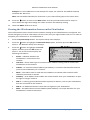
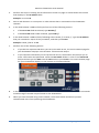
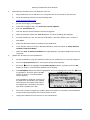
FlowStation User Manual for Shared Flow Applications August 25, 2015 Contents at a Glance Section 1 Section 2 Section 3 Section 4 Introduction Installing Shared Flow Components Configuring the BaseStation 3200 Irrigation Controller for Shared Flow Configuring the Flow Station Customer Service 1-866-294-5847 Baseline Inc. www.baselinesystems.com Phone 208-323-1634 FAX 208-323-1834 Toll Free 866-294-5847 ©2015 Baseline Inc. All Rights Reserved. Contents 1– INTRODUCTION ..................................................................................................................................1 Flow Monitoring .................................................................................................................. 1 Flow Management .............................................................................................................. 1 Understanding Shared Flow Design and Operation.............................................................. 1 Shared Flow Design Example .............................................................................................. 2 Understanding Shared Flow Terminology ............................................................................ 2 2 – INSTALLING SHARED FLOW COMPONENTS...............................................................................3 Installing the FlowStation and Communication Module....................................................... 3 Installing the Shared Flow biCoders .................................................................................... 3 Installing the BaseStation 3200 Irrigation Controllers .......................................................... 3 3 – CONFIGURING THE BASESTATION 3200 IRRIGATION CONTROLLER FOR SHARED FLOW ..........................................................................................................................................................4 Connecting a BaseStation 3200 Controller to the FlowStation ............................................. 4 Checking the BaseStation–FlowStation Connection Status................................................... 5 Setting Up a Static IP Address on the BaseStation 3200 ....................................................... 6 Understanding the Ethernet Settings on the BaseStation 3200 ............................................ 7 Configuring the Shared Flow Settings on the BaseStation 3200............................................ 8 Enabling Shared Flow for a POC on the BaseStation 3200 .................................................. 8 Assigning Programs to the FlowStation............................................................................... 9 Assigning Booster Pumps to the FlowStation ...................................................................... 9 Performance Considerations ............................................................................................. 10 4 – CONFIGURING THE FLOWSTATION .......................................................................................... 11 Understanding the FlowStation Interface .......................................................................... 11 FlowStation Front Panel Layout ........................................................................................ 11 On-Screen Help ................................................................................................................. 12 Restarting the FlowStation ................................................................................................ 12 Viewing the Controller Status Report................................................................................ 12 Understanding Controller Statuses ................................................................................... 13 Assigning the Shared Flow Devices .................................................................................... 13 Assigning Controllers to the Shared Flow Group ............................................................... 13 Enabling/Disabling an Assigned Controller........................................................................ 14 Assigning Booster Pumps .................................................................................................. 14 Enabling/Disabling an Assigned Booster Pump ................................................................. 15 Assigning Points of Connection (POC) ............................................................................... 16 Enabling/Disabling an Assigned Point of Connection (POC) .............................................. 16 Configuring the Shared Flow Settings ................................................................................ 17 Assigning POCs to a Mainline ............................................................................................ 17 Enabling a Mainline ........................................................................................................... 17 Configuring Concurrent Zones .......................................................................................... 17 Limiting a Mainline by Flow (Max Flow GPM) ................................................................... 18 Setting the Fill Time for a Mainline ................................................................................... 19 Setting Up Shared Flow Programs ..................................................................................... 19 FlowStation System Setup ................................................................................................ 20 Setting the FlowStation Date and Time ............................................................................. 20 Setting Up a Static IP Address on the FlowStation ............................................................ 21 Viewing the IP Information Screen on the FlowStation..................................................... 22 Setting Up the Web Server for Local LiveView .................................................................. 23 Page i Using Local LiveView to Remotely Operate the FlowStation ............................................. 23 Setting Up the Screen Display ........................................................................................... 25 Setting Up Security for the FlowStation ............................................................................ 25 Clearing the Programming on the FlowStation ................................................................. 26 Backing Up the FlowStation Programming ........................................................................ 26 Restoring the FlowStation Programming .......................................................................... 27 Updating the Firmware on the FlowStation ...................................................................... 27 Exporting Data from the FlowStation ................................................................................ 29 Enabling Diagnostics for Baseline Support ........................................................................ 29 Status Reports and Messages............................................................................................ 30 Viewing the Controller Status Report................................................................................ 30 Understanding Controller Statuses .............................................................................. 30 Viewing Additional Controller Status Details ............................................................... 31 Viewing the Program Status Report .................................................................................. 31 Understanding Program Statuses ................................................................................ 32 Viewing the Program Status Details ............................................................................. 32 Viewing the Booster Pump Status Report ......................................................................... 33 Understanding Booster Pump Statuses ....................................................................... 33 Viewing Additional Booster Pump Status Details ......................................................... 34 Viewing the POC Status Report ......................................................................................... 34 Understanding POC Statuses ....................................................................................... 34 Viewing Additional POC Status Details......................................................................... 35 Viewing the Mainline Status Report .................................................................................. 35 Understanding Mainline Statuses ................................................................................ 36 Viewing Additional Mainline Status Details ................................................................. 36 Viewing Operator Messages ............................................................................................. 37 Page ii Baseline FlowStation User Manual 1– Introduction Baseline’s FlowStation allows up to 30 BaseStation 3200 irrigation controllers to share water resources including points of connection (POCs), master valves, and booster pumps. The BaseStation 3200 irrigation controllers and the FlowStation communicate with each other through a local TCP/IP network connection. The connections can be a combination of wired Ethernet, Wi-Fi, and Ethernet radios. The FlowStation can manage 20 points of connection (POC), 20 mainlines, and 99 programs. Each mainline aggregates the available water from each POC, and the FlowStation intelligently allocates water resources to the programs running on the controllers in the shared flow group. Each program can be assigned a priority, and the FlowStation will allocate water to the highest priority programs first. Flow Monitoring The BaseStation 3200 monitors the POC for high and unexpected flow events, reports faults to the FlowStation, and shuts the POC down. The FlowStation will take immediate action when a flow fault is detected and discontinue use of the faulted point of connection for the shared flow group. Flow Management The FlowStation will maximize the number of valves and controllers that can operate at once based on the amount of water that is available. You can configure the FlowStation to manage the flow by electrical concurrency or by available GPM. Understanding Shared Flow Design and Operation A shared flow group consists of several BaseStation 3200 irrigation controllers with Shared Flow biCoders connected, a FlowStation, the POCs, and the mainlines. The FlowStation is the monitor for the entire group of controllers. It monitors the available water and allocates the water to the controllers based on priorities and concurrent zone settings. After all components in the shared flow group are communicating and configured, the BaseStation 3200 asks the FlowStation for water to run a program. The FlowStation allocates water based on concurrent zones and available water. The programs will start based on their priorities. The controller sends status and flow information to the FlowStation once per minute. You can view device information on the FlowStation control panel. Every BaseStation 3200 can be easily upgraded to share water resources with the addition of the Shared Flow biCoder. The Shared Flow biCoder connects directly to the two-wire path and enables the shared flow features in the BaseStation 3200. 1– Introduction Page 1 Baseline FlowStation User Manual Shared Flow Design Example Multiple Points of Connection on a Shared Looped Mainline Understanding Shared Flow Terminology The irrigation industry uses a variety of terms to describe water supplies, piping structures, and flow scenarios. These terms may or may not have standard definitions in the industry. To avoid confusion, please review Baseline’s definitions for some of these common terms. flow device: A device that is capable of measuring water flow and water used, includes flow sensors and flow meters mainline: A pressurized pipe that supplies water from a point of connection (or from multiple points of connection) to the valves master valve (MV): A valve used to control when water is allowed to flow through that point of connection. Often used to protect the landscape from flooding in case of a ruptured main or a malfunctioning downstream valve. normally closed master valve (NCMV): An automatic valve through which no water will flow unless external influences are applied to cause the valve to open normally open master valve (NOMV): An automatic valve through which water will flow unless external influences are applied to close the valve point of connection (POC): Also known as a water source. This term refers to the place where the irrigation system is connected to a water supply. In the case of a system that has access to water from multiple supplies, such as harvested rainwater, reclaimed water, and potable water, this term is also used to distinguish one water supply from another. For example: POC 1, POC 2, etc. Page 2 1– Introduction Baseline FlowStation User Manual 2 – Installing Shared Flow Components Installing the FlowStation and Communication Module Install the FlowStation enclosure and the communication module according to the instructions that came with the equipment. Make sure the FlowStation is powered up and the communication module is connected. To find the required tasks for setting up the FlowStation, refer to the section on Configuring the FlowStation on page 11 of this User Manual. Installing the Shared Flow biCoders Connect a 3200UPG-SF biCoder to the two-wire path of each BaseStation 3200 irrigation controller that will be part of the shared flow group. Refer to the installation guide that came with the biCoder. The BaseStation 3200 controller recognizes that the Shared Flow biCoder has been installed, and the controller enables the shared flow features. Installing the BaseStation 3200 Irrigation Controllers Refer to the BaseStation 3200 User Manual to install and set up the controllers. To find the required tasks for setting up the BaseStation 3200 to use shared flow, refer to the section on Configuring the BaseStation 3200 Irrigation Controller for Shared Flow on page 4 of this User Manual. 2 – Installing Shared Flow Components Page 3 Baseline FlowStation User Manual 3 – Configuring the BaseStation 3200 Irrigation Controller for Shared Flow The FlowStation and BaseStation 3200 controllers in a shared flow group communicate with each other over a network. In some implementations, a stand-alone network is established between the controllers and the FlowStation, and this network does not need to be connected to the Internet. In other implementations, the FlowStation will be connected to an existing network that the controllers are already connected to. If the FlowStation and the BaseStation 3200 controllers in the shared flow group will connect to an existing network that is managed by a network administrator, you need to ask the admin to set up a static IP address for the FlowStation. Also ask the admin for the Subnet Mask and the Gateway settings for the network. If the BaseStation 3200 controllers are already connected to this network, you need to connect the FlowStation to the network (refer to Setting Up a Static IP Address on the FlowStation on page 21), and then connect the controllers to the FlowStation (refer to Connecting a BaseStation 3200 Controller to the FlowStation). If the devices in the shared flow group will connect to a stand-alone network, make sure the communication modules in the FlowStation and the BaseStation 3200 controllers are powered up and communicating. Set up the static IP addresses on the FlowStation and the controllers. After all devices are on the network, you can connect the controllers to the FlowStation (refer to Connecting a BaseStation 3200 Controller to the FlowStation). Connecting a BaseStation 3200 Controller to the FlowStation After your FlowStation is powered up and connected to the network, you need to connect your BaseStation 3200 irrigation controllers to the FlowStation. IMPORTANT NOTE! If you are connecting a BaseStation 3200 controller that is already in service to a FlowStation, make sure that the controller has been updated to the most current firmware version. The current firmware version is listed on the Firmware Updates page on the Baseline website (www.baselinesystems.com). Refer to the BaseStation 3200 User Manual to find instructions for updating the controller firmware. 1. Ensure that the Shared Flow biCoder has been connected to the controller’s two-wire path. Refer to the installation instructions that came with the biCoder. 2. Get the IP Address from the FlowStation. a. On the FlowStation, press the System Setup button. b. Press the button to select the Network Setup option, and then press the OK button. The Network Setup menu displays. c. Press the button to select the IP Info option, and then press the OK button. The IP Info screen displays. d. Find the IP address of the FlowStation in the IP ADDR field, and then write it down. Page 4 3 – Configuring the BaseStation 3200 Irrigation Controller for Shared Flow Baseline FlowStation User Manual 3. On a BaseStation 3200 irrigation controller that you want to connect to the FlowStation, turn the dial to the Network position. 4. Press the Next button to highlight the FlowStation Setup option. 5. Press the Enter button. The Network screen displays. 6. In the Flow Station Control field, press the + button to change the setting to Enabled. 7. Press the Next button to move to the first cell of the Flow Station IP field. 8. Press the + button to change the number to match the first group of numbers in the IP address of the FlowStation. Note: Press and hold the + button or the – button to rapidly increase or decrease the number in the field. 9. Complete the IP address by pressing the Next button to move to the next cell of the Flow Station IP field, and then pressing the + button to change the number. 10. Repeat steps 3 through 9 on each BaseStation 3200 irrigation controller that you want to connect to the FlowStation. Note: The connection between the controller and the FlowStation is not complete until you assign the controller on the FlowStation. Refer to Assigning Controllers to the Shared Flow Group on page 13. Checking the BaseStation–FlowStation Connection Status When the dial on the BaseStation 3200 controller is in the RUN position, review the status of the FlowStation connection in the FlowStn field in the upper-right corner of the screen. • Wait Auth: This status displays after the FlowStation-controller network connection has been established and you have connected the controller to the FlowStation. This status continues to display until you add the controller to the shared flow group in the FlowStation. Refer to Assigning the Controllers to the Shared Flow Group on page 13. • Connected: This status displays after the controller has been added to the shared flow group. 3 – Configuring the BaseStation 3200 Irrigation Controller for Shared Flow Page 5 Baseline FlowStation User Manual Setting Up a Static IP Address on the BaseStation 3200 Perform the following procedure if you find that the BaseStation 3200 controllers in the shared flow group need to be assigned a static IP address. 1. Connect and configure the communication module. Check the status lights and indicators on your communication equipment to ensure that it is powered up and appears to be sending and receiving data. 2. Turn the dial to the Network position. 3. Press the Next button to highlight the Ethernet Setup option, and then press Enter. The Setup Ethernet screen displays. 4. In the IP Address Mode field, press the + or – button to change the value to Static IP. Note: For a definition of the fields on the Setup Ethernet screen, refer to Understanding the Ethernet Settings on the BaseStation 3200 on page 7. 5. Determine the static IP address that you will assign to the BaseStation 3200. The IP address is based on the IP addresses of the other devices on the network, but it must have a unique last digit. Example: The communication modules in your FlowStation and controllers have factory-assigned IP addresses ranging from 192.168.111.100 to 192.168.111.106. You can set the static IP address on the BaseStation 3200 to 192.168.111.107. Additional BaseStation 3200 controllers in this shared flow group would use 192.168.111.108, 192.168.111.109, and so on. 6. Press the Next button to highlight the first box in the IP Addr field. Press the Previous or Next button to move to the box that you want to change. Press the + or – button to change the value in the field. Note: To rapidly increase or decrease the value, press and hold the + button or the – button. 7. Press the Next button to move to the Subnet Mask field. Use the procedure described in step 6 to move within the boxes and change the values. A typical value for the Subnet Mask is 255.255.255.0 Note: Set the Subnet Mask for all devices in your shared flow group to the same value. 8. Press the Next button to move to the Default Gateway field. Use the procedure described in step 6 to move within the boxes and change the values. Example: For the IP addresses in the example for step 5, the value for the Default Gateway would be 192.168.111.1. Note: Set the Default Gateway for all devices in your shared flow group to the same value. 9. Leave the Preferred DNS Server fields set to zeros. Page 6 3 – Configuring the BaseStation 3200 Irrigation Controller for Shared Flow Baseline FlowStation User Manual Understanding the Ethernet Settings on the BaseStation 3200 When your controller is connected to a network with a supported communication module, the system automatically assigns the networking addresses that enable the connection. You might need to refer to this information in order to complete your connection or to troubleshoot it. 1. Connect and configure the communication module. Check the status lights and indicators on your communication equipment to ensure that it is powered up and appears to be sending and receiving data. 2. Turn the dial to the Network position. 3. Press the Next button to highlight the Ethernet Setup option, and then press Enter. The Setup Ethernet screen displays the following information: DHCP (Dynamic Host Configuration Protocol) – The default network configuration for the BaseStation 3200. This protocol allows your controller to automatically obtain an IP address which enables the connection to the Internet. Every time you restart your controller, it retrieves a new IP address. Static IP – An IP address that is permanently assigned IP Addr – An Internet Protocol address (IP address) is a number that identifies a device (such as the controller) on a network. Subnet Mask – The subnet mask is used with an IP address to indicate what network traffic should be permitted or denied. Default Gateway – An IP address that enables the network traffic from your controller to pass through to a larger network Preferred DNS Server 1 – A naming system (Domain Name System) for devices, such as your controller, that are connected to the Internet Preferred DNS Server 2 – An additional domain name that is assigned to your controller Physical (MAC) Address – The Media Access Control address (MAC address) is a unique identifier for your controller’s network connection. 3 – Configuring the BaseStation 3200 Irrigation Controller for Shared Flow Page 7 Baseline FlowStation User Manual Configuring the Shared Flow Settings on the BaseStation 3200 When a BaseStation 3200 irrigation controller is part of a shared flow group, follow the instructions in the User Manual to perform the following tasks on the controller: • Assign and configure the zones. • Assign and configure the master valves, flow meters, and booster pumps. • Set up the programs and their start/stop/pause conditions. • Set up the POCs – a POC that is assigned to the FlowStation will maintain all of its settings except priority and rationing. To configure the controller for shared flow, perform the following tasks described in this User Manual: • Connect the BaseStation 3200 to the FlowStation (refer to Connecting a BaseStation 3200 Controller to the FlowStation on page 4). • Turn over control of the POCs to the FlowStation (refer to Enabling Shared Flow for a POC on the BaseStation 3200 on page 8). • Assign the programs to the FlowStation (refer to Assigning Programs to the FlowStation on page 9). • Assign the Booster Pumps to the FlowStation (refer to Assigning Booster Pumps to the FlowStation on page 9). When the BaseStation 3200 configuration is complete and a start condition is met for a program that is assigned to the FlowStation, the controller asks the FlowStation for water. After the FlowStation allocates the water, the program will start. After the resources are “shared” they can no longer be used directly by the controller. The FlowStation will decide when these resources are used. Enabling Shared Flow for a POC on the BaseStation 3200 1. On the BaseStation 3200 irrigation controller, turn the dial to the Flow position. 2. Press the Next button to highlight the Assign Water Sources to Mainlines option. 3. Press the Enter button. The POC to Mainline screen displays. 4. In the Point of Connection column, press the + or – button to select the POC that you want to assign to the FlowStation. 5. Press the Next button to move to the Mainline column. 6. Press the + or – button to display FlowStn in the Mainline column. 7. Repeat steps 1 – 6 on each BaseStation 3200 irrigation controller that will be sharing flow. Page 8 3 – Configuring the BaseStation 3200 Irrigation Controller for Shared Flow Baseline FlowStation User Manual Assigning Programs to the FlowStation 1. On the BaseStation 3200 irrigation controller, turn the dial to the Flow position. 2. Press the Next button to highlight the Assign Programs to Mainlines option. 3. Press the Enter button. The Progs to Mainline screen displays. 4. In the Program column, press the + or – button to select the program that you want to assign to the FlowStation. 5. Press the Next button to move to the Mainline column. 6. Press the + or – button to display FlowStn in the Mainline column. Assigning Booster Pumps to the FlowStation Note: The pump device that you want to assign to the FlowStation must be assigned to a master valve slot in the BaseStation 3200 before you can assign it to the FlowStation. Refer to Searching for and Assigning Pump Start Devices and Master Valves in the BaseStation 3200 User Manual. 1. On the BaseStation 3200 irrigation controller, turn the dial to the Water Sources position. 2. Press the Next button to highlight the Booster Pumps Program Setup option. 3. Press the Enter button. The Booster Pumps screen displays. 4. In the Decoder field, press the + or – button to display the master valve slot where the booster pump device is assigned. The serial number of the device displays next to the field. 5. In the Use As Booster Pump field, press the + button until FlowStn displays. 3 – Configuring the BaseStation 3200 Irrigation Controller for Shared Flow Page 9 Baseline FlowStation User Manual Performance Considerations When a BaseStation 3200 is part of a shared flow group, some controller operations might behave differently than you expect. Manual Run – When a manual run is started, all programs on that mainline will be paused while the manual run is in progress. If you have multiple controllers in the shared flow group assigned to the same mainline, the programs on all controllers will be paused. Learn Flow – When a learn flow is started, all programs on that mainline will be paused while the learn flow operation is in progress. If you have multiple controllers in the shared flow group assigned to the same mainline, the programs on all controllers will be paused. Water Rationing – When you turn over control of a POC to the FlowStation, you cannot set intelligent water rationing on the BaseStation 3200 for that POC. Program Priorities – The priority (high, medium, low) assigned to a program on the BaseStation 3200 indicates the order in which the controller will ask the FlowStation for water to start the program. The priority setting on the FlowStation controls how water is allocated to controllers. The FlowStation uses a priority scale of 1 – 10, where 1 is the highest priority. This scale allows you to prioritize programs from multiple controllers at a more granular level. The priority setting on the FlowStation takes precedence over the program priority setting on the controller. Refer to Setting Up Shared Flow Programs on page 19 for instructions on setting the program priority in the FlowStation. Note: If all program priorities on the controllers and the FlowStation are equal, the programs will start based on the slot in which the controller is assigned on the FlowStation. BaseManager – If your BaseStation 3200 is connected to BaseManager, you can view all controller statuses in BaseManager. You can also initiate manual runs on zones and programs from BaseManager. Note: The FlowStation is not yet supported on BaseManager. Page 10 3 – Configuring the BaseStation 3200 Irrigation Controller for Shared Flow Baseline FlowStation User Manual 4 – Configuring the FlowStation Understanding the FlowStation Interface Review this section to get familiar with the layout of the FlowStation interface. This information covers the components of the front panel, the On-Screen Help, the features of the main screen, as well as the zone status icons. FlowStation Front Panel Layout Display – The display shows the current state of the FlowStation and is used to program the FlowStation. Refer to Setting Up the Screen Display on page 25 for information about improving image quality in outdoor conditions including direct sunlight and low light. Main Menu Buttons – The buttons are used to select the various operating or programming menus of the FlowStation. An indicator light glows on the button for the menu that is active. Buttons – The buttons are used to select programming elements, change their values, and initiate operations. ENG/ESP Switch between the English and the Spanish interface on the FlowStation ? Display help for any screen 4 – Configuring the FlowStation Page 11 Baseline FlowStation User Manual + Increase the value of the highlighted field, or sequence through the available options in the selected field - Decrease the value of the selected field, or sequence through the available options in the selected field PRG Select the program that you want to modify Arrow Buttons Move within a screen OK Select an option or perform an action BACK Return to a previous screen or cancel an action On-Screen Help Press the ? button at any time to display the On-Screen Help. When the help displays, press the button to scroll through the text, and when you have finished using the help, press the ? button or the BACK button to return to the previous screen. Restarting the FlowStation If the FlowStation goes into an abnormal state and does not respond, you might need to restart it. Typically, we recommend that you call Baseline Support (866.294.5847) before you restart the FlowStation. 1. Press the OFF button. 2. Press and hold the ENG/ESP and ? buttons for approximately 5 seconds. 3. After the screen goes blank, release the buttons. The FlowStation restarts automatically. Viewing the Controller Status Report When the FlowStation is in the RUN menu, the Controller Status report typically displays on the screen. If you do not see “CONTROLLER STATUS” and the list of controllers, press the RUN button to make sure that the controller is in the RUN menu, and then press the BACK button to display the Status Report menu. Select the Controller Status option from the menu. Note: For information about the additional Controller Status details, refer to Viewing Additional Controller Status Details on page 31. Page 12 4 – Configuring the FlowStation Baseline FlowStation User Manual Understanding Controller Statuses The following icons identify the status of the controllers in the shared flow group: Icon Status Description Unassigned No controller is assigned Done The complete cycle has finished for this controller – including watering and soaking Waiting The controller is scheduled to run, but currently it is not watering or soaking Watering Watering is in progress Soaking The controller finished watering a zone and it is now soaking Paused A pause condition is in effect Disabled or Disconnected The controller is marked as being disabled or disconnected from the FlowStation Message There is a message associated with this controller Assigning the Shared Flow Devices Assigning Controllers to the Shared Flow Group IMPORTANT! You must connect the controllers to the FlowStation before you can assign them. Refer to Connecting a BaseStation 3200 Controller to the FlowStation on page 4. 1. On the FlowStation, press the Search & Assign button. The Assign menu displays. 2. Press the button to highlight the Controller option, and then press the OK button to select it. The Controller menu displays. 3. If the Device Assignment option is highlighted, press the OK button to select it. If Device Assignment is not highlighted, press the or button to highlight it, and then press the OK button. The Controller Assignment screen displays. 4 – Configuring the FlowStation Page 13 Baseline FlowStation User Manual 4. The serial numbers of all connected controllers display in the Action column. Press the or button to move through the list of controllers in the Action column. Highlight the serial number of the controller that you want to assign to the shared flow group. 5. Press the button to move to the Controller column. 6. Press the or button to move through the list of controllers. Highlight the number that you want to assign the controller to. 7. Press the OK button to select the highlighted controller number. The serial number of the controller that you selected in the Action column now displays next to the number in the Controller column. Note: The next serial number in the Action column is automatically highlighted. Press the or button in the Controller column to move to the next zone that you want to assign, and then press the OK button. 8. Continue until you have assigned all the controllers that you want to be part of this shared flow group. Enabling/Disabling an Assigned Controller 1. On the FlowStation, press the Search & Assign button. The Assign menu displays. 2. Press the button to highlight the Controller option, and then press the OK button to select it. The Controller menu displays. 3. Press the button to highlight the Device Setup option, and then press the OK button to select it. The Controller Device Setup screen displays. 4. In the first column, press the + or - button to select the number of the controller that you want to enable or disable. 5. Press the button to move to the Enabled field. A checkmark in the field means that the controller is enabled in the FlowStation. A blank field means that the controller is disabled. To change the setting, press the OK button. Assigning Booster Pumps IMPORTANT! You must assign the booster pump to the FlowStation in the BaseStation 3200 before you can assign it in the FlowStation. Refer to Assigning Booster Pumps to the FlowStation on page 9. 1. On the FlowStation, press the Search & Assign button. The Assign menu displays. Page 14 4 – Configuring the FlowStation Baseline FlowStation User Manual 2. Press the button to highlight the Booster Pump option, and then press the OK button to select it. The Booster Pump menu displays. 3. If the Device Assignment option is highlighted, press the OK button to select it. If Device Assignment is not highlighted, press the or button to highlight it, and then press the OK button. The Booster Pump Assignment screen displays. 4. When the FlowStation finds the booster pumps, their serial numbers display in the Action column. 5. Press the or button to move through the list of booster pumps in the Action column. Highlight the serial number of the booster pump that you want to assign to the shared flow group. 6. Press the button to move to the Booster Pump column. 7. Press the or button to move through the list of booster pumps. Highlight the number that you want to assign the booster pump to. 8. Press the OK button to select the highlighted booster pump number. The serial number of the booster pump that you selected in the Action column now displays next to the number in the Booster Pump column. Note: The next serial number in the Action column is automatically highlighted. Press the or button in the Booster Pump column to move to the next zone that you want to assign, and then press the OK button. 9. Continue until you have assigned all your booster pumps to the shared flow group. Enabling/Disabling an Assigned Booster Pump 1. On the FlowStation, press the Search & Assign button. The Assign menu displays. 2. Press the button to highlight the Booster Pump option, and then press the OK button to select it. The Booster Pump menu displays. 3. Press the button to highlight the Device Setup option, and then press the OK button to select it. The Booster Device Setup screen displays. 4. In the first column, press the + or – button to select the number of the booster pump that you want to enable or disable. 5. Press the button to move to the Enabled field. A checkmark in the field means that the booster pump is enabled in the FlowStation. A blank field means that the booster pump is disabled. To change the setting, press the OK button. 4 – Configuring the FlowStation Page 15 Baseline FlowStation User Manual Assigning Points of Connection (POC) IMPORTANT! You must enable shared flow for the POC in the BaseStation 3200 before you can assign the POC in the FlowStation. Refer to Enabling Shared Flow for a POC on the BaseStation 3200 on page 8. 1. On the FlowStation, press the Search & Assign button. The Assign menu displays. 2. Press the button to highlight the POC option, and then press the OK button to select it. The POC menu displays. 3. If the Device Assignment option is highlighted, press the OK button to select it. If Device Assignment is not highlighted, press the or button to highlight it, and then press the OK button. The POC Assignment screen displays. The POCs that have been enabled for shared flow in the controllers are listed in the Action column by the controller’s serial number followed by the POC number. Example: 3K80000:1 4. Press the or button to move through the list of POCs in the Action column. Highlight the number of the POC that you want to assign to the shared flow group. 5. Press the button to move to the POC column. 6. Press the or button to move through the list of POCs. Highlight the number that you want to assign the POC to. 7. Press the OK button to select the highlighted POC number. The number of the POC that you selected in the Action column now displays next to the number in the POC column. Note: The next serial number in the Action column is automatically highlighted. Press the or button in the POC column to move to the next zone that you want to assign, and then press the OK button. 8. Continue until you have assigned all your POCs to the shared flow group. Enabling/Disabling an Assigned Point of Connection (POC) 1. On the FlowStation, press the Search & Assign button. The Assign menu displays. 2. Press the button to highlight the POC option, and then press the OK button to select it. The POC menu displays. 3. Press the button to highlight the Device Setup option, and then press the OK button to select it. The POC Device Setup screen displays. 4. In the first column, press the + or – button to select the number of the POC that you want to enable or disable. 5. Press the button to move to the Enabled field. A checkmark in the field means that the POC is enabled in the FlowStation. A blank field means that the POC is disabled. To change the setting, press the OK button. Page 16 4 – Configuring the FlowStation Baseline FlowStation User Manual Configuring the Shared Flow Settings Assigning POCs to a Mainline A mainline can have up to 20 POCs assigned to it, but a POC can only be assigned to one mainline. 1. On the FlowStation, press the Flow Setup button. The Flow Setup menu displays. 2. Press the button to highlight the Main Line Setup option, and then press the OK button to select it. The Main Line Setup screen displays. 3. Press the button to highlight the mainline that you want to assign a POC to, and then press the OK button to select it. The Main Line # screen displays. 4. Press the button to highlight the POCs option, and then press the OK button to select it. The POCs that you assigned earlier display in a list. 5. Press the button to highlight the POC that you want to assign to the mainline, and then press the + or – button to place a checkmark in the field. 6. If you want to assign other POCs to this mainline, repeat step 5. Enabling a Mainline 1. On the FlowStation, press the Flow Setup button. The Flow Setup menu displays. 2. Press the button to highlight the Main Line Setup option, and then press the OK button to select it. The Main Line Setup screen displays. 3. Press the button to highlight the mainline that you want to enable/disable, and then press the OK button to select it. The Main Line # screen displays. 4. Press the button to highlight the Enable/Disable option, and then press the OK button to select it. The Enabled/Disabled screen for the mainline displays. 5. Press the button to move to the Enabled field. A checkmark in the field means that the mainline is enabled in the FlowStation. A blank field means that the mainline is disabled. To change the setting, press the OK button. Configuring Concurrent Zones The FlowStation allows up to 200 zones to run at the same time. 1. On the FlowStation, press the Flow Setup button. The Flow Setup menu displays. 2. Press the button to highlight the Main Line Setup option, and then press the OK button to select it. The Main Line Setup screen displays. 3. Press the button to highlight the mainline that you want to configure concurrent zones for, and then press the OK button to select it. The Main Line # screen displays. 4 – Configuring the FlowStation Page 17 Baseline FlowStation User Manual 4. Press the button to highlight the Flow Management option, and then press the OK button to select it. The Flow Management screen for the mainline displays. 5. In the Max Concurrent field, press the + or – button to change the value. 6. Press the button to move to the Limit Concurrent field, and then press the + or – button to change the value in the field. If the mainline is currently limited by the number of concurrent zones, a checkmark displays in the Limit Concurrent field. Press the + or – button to remove the checkmark. If mainline is currently not limited by the number of concurrent zones, there is no checkmark in the Limit Concurrent field. Press the + or – button to add a checkmark. Limiting a Mainline by Flow (Max Flow GPM) 1. On the FlowStation, press the Flow Setup button. The Flow Setup screen displays. 2. Press the button to highlight the Main Line Setup option, and then press the OK button to select it. The Main Line Setup screen displays. 3. Press the button to highlight the mainline that you want to configure concurrent zones for, and then press the OK button to select it. The Main Line # screen displays. 4. Press the button to highlight the Flow Management option, and then press the OK button to select it. The Flow Management screen for the mainline displays. 5. Press the button to move to the Max Flow GPM field, and then press the + or – button to change the value in the field. 6. Press the button to move to the Limit GPM field, and then press the + or – button to change the value in the field. If the zones operating from this mainline are currently limited by the max flow, a checkmark displays in the Limit GPM field. Press the + or – button to remove the checkmark. If the zones operating from this mainline are not currently limited by the max flow, there is no checkmark in the Limit GPM field. Press the + or – button to add a checkmark. Page 18 4 – Configuring the FlowStation Baseline FlowStation User Manual Setting the Fill Time for a Mainline 1. On the FlowStation, press the Flow Setup button. The Flow Setup screen displays. 2. Press the button to highlight the Main Line Setup option, and then press the OK button to select it. The Main Line Setup screen displays. 3. Press the button to highlight the mainline that you want to set the fill time for, and then press the OK button to select it. The Main Line # screen displays. 6. Press the button to highlight the Fill Time option, and then press the OK button to select it. The Fill Time screen for the mainline displays. 7. Press the + button to change the time in the Fill Time field. Setting Up Shared Flow Programs The user selects which programs must get their water from the FlowStation. Note: Refer to Assigning Programs to the FlowStation on page 9. 1. On the FlowStation, press the Program Setup button. The Program Setup screen displays the list of the BaseStation 3200 controllers that have been assigned to the FlowStation. 2. Press the or button to highlight the controller that has the program that you want to set up, and then press the OK button. The Program Setup screen displays. 3. Press the PRG button on the display panel to select the program that you want to work with. The controller number and program number display in the upper-left corner of the screen. Example: Cn 1, Pr 1 = Controller 1 and Program 1 4. In the Priority field, press the + or – button to change the priority for this program. The priority settings are 1 through 10 where 1 (the default setting) is the highest priority. The priority setting on the FlowStation controls how water is allocated to controllers and programs, and the program priority setting on the BaseStation 3200 manages the sequence for program starts. The priority setting on the FlowStation takes precedence over the setting on the controller, so a program that has high priority in the controller might be scheduled to start, but if it has low priority in the FlowStation, it might not be allocated the water that it needs to run. Note: For most shared flow scenarios, we recommend that you leave the Priority for all programs set to the default (1) on the FlowStation. 4 – Configuring the FlowStation Page 19 Baseline FlowStation User Manual 5. Press the button to highlight the Main Line field, and then press the + or – button to select the mainline that you want this program to use. Note: A program can only be assigned to one mainline. 6. If you want to enable a booster pump for this program, press the button to highlight the Booster Pump field, and then press the OK button. The Booster Pump screen displays, and the booster pumps that you assigned to the FlowStation are listed. 7. Perform one of the following actions: To enable a booster pump for this controller and program, press the button to highlight the booster pump, and then press the + or – button to place a checkmark in the field. To disable booster pump for this controller and program, press the button to highlight the booster pump, and then press the + or – button to remove the checkmark from the field. FlowStation System Setup Setting the FlowStation Date and Time Set or change the FlowStation date and time to match the current date and time. WARNING! Changing the date and time can cause watering events to be missed. 1. Press the System Setup button. The System Maintenance menu displays. 2. The Time & Date Setup option should be highlighted. If it is not highlighted, press the or button to highlight it, and then press the OK button. The Time & Date Setup screen displays. 3. In the Time field, notice that the hours placeholder is highlighted. 4. To change the time, press the + or – button. To move to the minutes placeholder, press the button. Press the button to move to the Date field. Press the or button to move to the date field that you want to change. Press the + or – button to change the value in the field. Note: The Weekday field is automatically filled in based on the date that was entered. 5. Press the button to move to the Time Format field, and then press the + or – button to change the value in the field. This field enables you to switch the time format between AM/PM and 24 hour settings. Page 20 4 – Configuring the FlowStation Baseline FlowStation User Manual Example: 6. In AM/PM format 10:00A and 10:00P In 24 hour format 10:00 and 22:00 When you have finished making changes, press the RUN button. Setting Up a Static IP Address on the FlowStation In order to have the FlowStation communicate with the BaseStation 3200 controllers in the shared flow group, the FlowStation must be connected to a network with a supported communication module. You need to assign a static IP address to the FlowStation to enable the BaseStation 3200 irrigation controllers in the shared flow group to connect to the FlowStation. 1. Make sure the communication module in your FlowStation is powered up and communicating with the network. 2. On the FlowStation, press the System Setup button. The System Setup menu displays. 3. Press the button to highlight the Network Setup option, and then press the OK button to select it. The Network Setup menu displays. 4. The IP Setup option should be highlighted. If it is not highlighted, press the or button to highlight it, and then press the OK button. The IP Setup screen displays. 5. Press the + or – button to remove the checkmark in the DHCP Enabled field. The fields for the network settings display. Note: For an explanation of the settings, refer to Viewing the IP Information Screen on the FlowStation on page 22. 6. Determine the static IP address that you will assign to the FlowStation. The IP address is based on the IP addresses of the other devices on the network, but it must have a unique last digit. Example: The devices in your shared flow group are connected to a stand-alone network that does not have Internet access. The communication modules in your FlowStation and controllers have factory-assigned IP addresses in the range 192.168.111.100 192.168.111.105. You can set the static IP address on the FlowStation to 192.168.111.106. 7. Press the button to highlight the first digits in the IP Addr field. Press the or button to move to the digits that you want to change. Press the + or – button to change the value in the field. Note: To rapidly increase or decrease the value, press and hold the + button or the – button. 8. Press the button to move to the Mask field. Use the procedure described in step 7 to move within the digits and change the values. A typical value for the Subnet Mask is 255.255.255.0 Note: Set the Subnet Mask for all devices in your shared flow group to the same value. 9. Press the button to move to the Gateway field. Use the procedure described in step 7 to move within the digits and change the values. 4 – Configuring the FlowStation Page 21 Baseline FlowStation User Manual Example: For the IP addresses in the example for step 6, the value for the Default Gateway would be 192.168.111.1. Note: Set the Default Gateway for all devices in your shared flow group to the same value. 10. Press the button to move to the DNS 1 field. Use the procedure described in step 7 to move within the digits and change the values to match the Gateway setting. 11. Leave the DNS 2 field set to zeros. Viewing the IP Information Screen on the FlowStation The IP Information screen shows how the network settings on the FlowStation are configured. You cannot change any of the IP information on this screen, but you might need to refer to it in order to complete your connection or to troubleshoot it. 1. Press the System Setup button. The System Setup menu displays. 2. Press the button to highlight the Network Setup option, and then press the OK button to select it. The Network Setup menu displays. 3. Press the button to highlight the IP Info option, and then press the OK button to select it. The IP Info screen displays the following information: Status – Indicates whether the FlowStation is connected to the network. Interface – Shows what type of communication module is being used to connect the FlowStation to the network. IP Addr – An Internet Protocol address (IP address) is a number that identifies a device (such as the FlowStation) on a network. Mask – The subnet mask is used with an IP address to indicate what network traffic should be permitted or denied. Gateway – An IP address that enables the network traffic from your FlowStation to pass through to a larger network. DNS 1 – A naming system (Domain Name System) for devices, such as your FlowStation, that are connected to the network. DNS 2 – An additional domain name that is assigned to your FlowStation. MAC – The Media Access Control address (MAC address) is a unique identifier for your FlowStation’s network connection. Page 22 4 – Configuring the FlowStation Baseline FlowStation User Manual Setting Up the Web Server for Local LiveView If you can connect a computer or other mobile device to the FlowStation network, you can enable the FlowStation’s web server and use Local LiveView™ to remotely operate the FlowStation. IMPORTANT NOTE! You cannot use Local LiveView to remotely operate the FlowStation from outside the local network. 1. Make sure the communication module in your FlowStation is powered up and communicating with the network. 2. Press the System Setup button. The System Setup menu displays. 3. Press the button to highlight the Network Setup option, and then press the OK button to select it. The Network Setup menu displays. 4. Press the button to highlight the Web Server Setup option, and then press the OK button to select it. The Web Server Setup screen displays. 5. In the Enabled field, press the + button to display a checkmark. Additional fields display on the screen. 6. Press the button to move to the Force SSL field. Secure Sockets Layer (SSL) allows the FlowStation to communicate across a network in a secure manner. If you want to force SSL, press the + button to display a checkmark in the field. Note: When Force SSL is selected, the user needs to type HTTPS:// before the IP Address. Refer to the steps in Using Local LiveView to Remotely Operate the FlowStation on page 23. 7. Press the button to move to the Require PIN field. If you want to require users to enter a personal identification number (PIN) to access the web server, press the + button to display a checkmark in the field. 8. Perform one of the following actions: 9. If you did not select the Require PIN field, skip to step 9. If you selected the Require PIN field, press the button to move to the PIN field. Press the or button to move to the digit that you want to change, and then press + or – button to change the number. Continue to the procedure for using Local LiveView to remotely operate the FlowStation on page 23. Using Local LiveView to Remotely Operate the FlowStation If you can connect a computer or other mobile device to the FlowStation network, you can enable the FlowStation’s web server and then use Local LiveView™ to remotely operate the FlowStation. IMPORTANT NOTE! You cannot use Local LiveView to remotely operate the FlowStation from outside the local network. 1. Make sure the communication module in your FlowStation is powered up and communicating with the network. 2. Perform the steps in Setting Up the Web Server on page 23. Note whether the Force SSL field is selected. 4 – Configuring the FlowStation Page 23 Baseline FlowStation User Manual 3. Perform the steps in Viewing the IP Information Screen on page 22. Write down the number that displays in the IP Address field. Example: 10.11.12.88 4. Start a web browser on a computer or other device that is connected to the FlowStation network. 5. In the web browser’s address field, perform one of the following actions: 6. If the Force SSL field IS selected, type HTTPS:// If the Force SSL field is NOT selected, type HTTP:// In the web browser’s address field, following either HTTPS:// or HTTP://, type the IP Address that you recorded in step 3 of this procedure, and then press Enter. Example: HTTPS://10.11.12.88 7. Perform one of the following actions: If you did not require a PIN when you set up the web server, the Local LiveView page for your FlowStation displays in the browser. Continue with step 8. If you required a PIN when you set up the web server, the browser will prompt you to enter a username and password. Leave the Username field as is. Click in the Password field, and then type the PIN. Click the OK button or press Enter. The Local LiveView page for your FlowStation displays in the browser as illustrated below. 8. In the browser, use the mouse to click a button on the Local LiveView interface. All commands issued through LiveView are performed on the FlowStation. 9. When you have finished using Local LiveView, close the browser window to prevent unauthorized users from operating the FlowStation. Page 24 4 – Configuring the FlowStation Baseline FlowStation User Manual Setting Up the Screen Display You can adjust the brightness and contrast on the FlowStation display screen to provide better visibility in a variety of lighting conditions and to accommodate a variety of viewing angles. You can also set a time limit for the backlight to be turned off. 1. Press the System Setup button. The System Setup menu displays. 2. Press the button to highlight the Display Setup option, and then press the OK button to select it. The Display Setup screen displays. 3. Press the + or – button to change the number in the Screen Contrast field. A lower number indicates less contrast and a higher number indicates more contrast. To rapidly increase or decrease the value, press and hold the + button or the – button. 4. When the screen contrast appears to be suitable for the conditions, stop changing the number. 5. Press the button to move to the Brightness field, and then press the + or – button to change the number. Note: You cannot increase the value in the Brightness field greater than 100%. 6. Press the button to move to the Timeout field, and then press the + or – button to change the number. This setting enables you to control how long the display remains illuminated before it goes dark. Setting Up Security for the FlowStation In the FlowStation you can set up the following levels of security access: • Admin – Grants access to all FlowStation functions • Programmer – Grants access to all FlowStation functions except the Security function • Operator – Grants access to the Main screen and the Status Report menu After you enable the security and set up the PINs, restart the FlowStation. Users will be prompted to enter their PIN when they press one of the menu buttons on the FlowStation. If the user does not have access to the menu, he/she will see the message “Invalid PIN.” IMPORTANT NOTE! When a user accesses the FlowStation with a PIN, the FlowStation will maintain that level of access for 1 hour. When that time is up, anyone who tries to use the FlowStation will be prompted to enter a PIN. 1. Press the System Setup button. The System Setup menu displays. 2. Press the button to highlight the Security Setup option, and then press the OK button to select it. The Security Setup screen displays. 3. Press the + button to display a checkmark in the Enabled field. The PIN fields for the security levels display. 4 – Configuring the FlowStation Page 25 Baseline FlowStation User Manual 4. Press the button to highlight the first digit of the Admin PIN, and then press the + or – button to change the number. 5. Press the button to move to the next digit, and then press the + or – button to change the number. Repeat this step until you have configured all digits of the PIN. 6. Press the button to highlight the next PIN, and then configure all digits of the PIN. Repeat until you have configured all of the PINs. Clearing the Programming on the FlowStation This function will clear or erase all programming information from the FlowStation. We recommend that you use this function only as directed by Baseline Support. IMPORTANT NOTE! Never clear your programming data without having a current backup available for a restore. Refer to Backing Up the FlowStation Programming on page 26. 1. Press the System Setup button. The System Setup menu displays. 2. Press the button to highlight the Clear Programming option, and then press the OK button to select it. The Clear Programming screen displays. 3. To clear all programming data, press the + button. Note: To exit this screen without clearing all programming in the FlowStation, press the BACK button. Backing Up the FlowStation Programming The FlowStation allows you to back up the programming to a USB drive (also called a flash drive or a thumb drive). We recommend that you back up a stable version of your FlowStation’s programming to a USB drive on a regular basis. You can save 5 backups identified by date and time. We recommend that you create a backup before you make significant changes to the programming on your FlowStation. After you verify that the new programming is satisfactory, create a new backup to preserve those changes. 1. Plug the USB drive into the USB port on the FlowStation. 2. Press the System Setup button. The System Setup menu displays. 3. Press the button to highlight the Backup & Restore option, and then press the OK button to select it. The Backup & Restore screen displays. 4. The USB Backup option should be highlighted. If it is not highlighted, press the button to highlight it, and then press the OK button to select it. The USB Backup screen displays. Page 26 4 – Configuring the FlowStation Baseline FlowStation User Manual 5. Press the OK button to back up the programming data to the USB drive under the currently selected location (1-5). The FlowStation writes the data to a folder on the USB drive that is named with the FlowStation’s serial number. 6. When the FlowStation has finished writing the backup file, unplug the USB drive from the USB port. Restoring the FlowStation Programming This function restores all programming information in the FlowStation from a backup that you made. We recommend that you use this function only as directed by Baseline Support. 1. Plug the USB drive that has the backup file on it into the USB port on the FlowStation. 2. Press the System Setup button. The System Setup menu displays. 3. Press the button to highlight the Backup & Restore option, and then press the OK button to select it. The Backup & Restore screen displays. 4. Press the button to highlight the USB Restore option, and then press the OK button to select it. The USB Restore screen displays. 5. Press the button to highlight the backup version that you want to use for the restore, and then press the OK button to select it. The restore selection screen displays. 6. Press the button to highlight the type of restore that you want to perform, and then press the OK button to restore the programming data from the backup stored on the USB drive. 7. When the FlowStation has finished restoring the programming from the backup file, unplug the USB drive from the USB port on the FlowStation. Updating the Firmware on the FlowStation Firmware updates are free for the life of any FlowStation as long as the hardware is compatible. Baseline will periodically release firmware upgrades that enhance the usefulness of our products or fix the occasional bug. You get the firmware update for your FlowStation from the Baseline web site with a USB drive. You will need a computer with a USB port. This computer must have access to the Internet. You also need a USB drive. You download the firmware from the Baseline web site to the USB drive. Then, you take the USB drive to the FlowStation and install the update. We recommend that you back up your current configuration before starting this process in case you need to restore your system. Refer to Backing Up the FlowStation Programming on page 26. Note: The following procedure assumes that your computer is running Microsoft Windows. 4 – Configuring the FlowStation Page 27 Baseline FlowStation User Manual 1. Download the firmware from the Baseline web site. a. Plug a USB drive into a USB port on a computer that is connected to the Internet. b. Go to the Baseline web site at the following URL: www.baselinesystems.com 2. c. On the home page, click Support. d. In the left navigation bar, click Firmware Version Updates. e. Click the FlowStation tab. f. Click the button to download the firmware upgrade. g. When prompted, choose the Save As option. The Save As dialog box displays. h. Find the USB drive in the list of drives and folders, and then double-click to select it. i. Click Save. j. Close the Windows Explorer window for the USB drive. k. In the System Tray area of your Windows Desktop, click the option to Safely Remove Hardware and Eject Media. l. When the Safe to Remove Hardware message displays, unplug the USB drive from the computer. Update the firmware on the FlowStation. a. On the FlowStation, plug the USB drive that has the Update file on it into the USB port. b. Press the System Setup button. The System Setup menu displays. c. Press the button to highlight the Firmware Update option, and then press the OK button to select it. The Firmware Update menu displays. d. The USB Update option should be highlighted. If it is not highlighted, press the button to highlight it, and then press the OK button to select it. The USB Update screen displays. The FlowStation reads the contents of the USB drive and displays the update information in the Status field. When the update file is available, the status line reads “Update File is OK.” e. Press the + button to apply the update. When the update is complete, the FlowStation restarts and briefly displays the new firmware version. f. Unplug the USB drive from the port on the FlowStation. Page 28 4 – Configuring the FlowStation Baseline FlowStation User Manual Exporting Data from the FlowStation The FlowStation keeps a record of all changes made to the FlowStation and all actions that occur on the FlowStation. Because these logs are stored in the FlowStation’s internal memory, they are somewhat limited in scope, but they can still prove useful for tracking configuration changes or program start/stop times. 1. Plug a USB drive into the USB port on the FlowStation. 2. Press the System Setup button. The System Setup menu displays. 3. Press the button to highlight the Export Data option, and then press the OK button to select it. The Export Data screen displays. 4. Press the OK button to select Export Event Logs. The event log is written to the USB drive and the FlowStation notifies you when the process is complete. 5. Unplug the USB drive from the USB port on the FlowStation. When you plug the USB drive into a computer, you will find the exported files on the USB drive in a folder labeled with the FlowStation’s serial number. Enabling Diagnostics for Baseline Support If you are working with Baseline Support to troubleshoot a problem on your FlowStation, the support specialist may ask you to enable additional diagnostic logs that will help track down the problem. 1. Press the System Setup button. The System Setup menu displays. 2. Press the button to highlight the System Settings option, and then press the OK button to select it. The System Settings screen displays. 3. Perform any of the following actions as directed by Baseline Support: Copy the full event log to a USB drive: Plug a USB drive into the USB port on the FlowStation. Press the button to move to the Log to USB field, and then press the + or – button to put a checkmark in the field. The support specialist will indicate how long you need to leave the USB drive plugged in Capture the status of all connected devices: Press the button to move to the Log Device Status field, and then press the + or – button to put a checkmark in the field. Capture all input/output on the FlowStation: Press the button to move to the Log FlowStation IO field, and then press the + or – button to put a checkmark in the field. 4 – Configuring the FlowStation Page 29 Baseline FlowStation User Manual Status Reports and Messages The main screen shows information about the operating state of the FlowStation. The FlowStation provides the following categories of reports and each category can have multiple reports. • Controller Status • POC Status • Program Status • Mainline Status • Master Valve/Pump Status • Operator Messages Viewing the Controller Status Report 1. When the FlowStation is in the Run menu, the Controller Status report typically displays on the screen. If you do not see “CONTROLLER STATUS” and the list of controllers, press the RUN button to make sure that the FlowStation is in the Run menu, and then press the BACK button to display the Status Report menu. 2. The Controller Status option should be highlighted. If it is not, press the or button to highlight it, and then press the OK button. The Controller Status screen displays. 3. To return to the Status Report menu, press the BACK button. Understanding Controller Statuses The following icons identify the status of the controllers in the Shared Flow Group: Icon Page 30 Status Description Unassigned No controller is assigned Done The complete cycle has finished for this controller – including watering and soaking Watering Watering is in progress Paused A pause condition is in effect OFF The controller is set to OFF Disabled The controller is marked as being disabled Disabled or Disconnected The controller is marked as being disabled or disconnected from the FlowStation Message There is a message associated with this controller 4 – Configuring the FlowStation Baseline FlowStation User Manual Viewing Additional Controller Status Details 1. Display the Controller Status Report as described in the Viewing the Controller Status Report topic above. 2. Press the button. The Controller Status details for the first controller display. Controller – Shows the sequential number of the controller based on the slot in which this controller is assigned on the FlowStation Status – Shows the status of the connection between this controller and the FlowStation Serial Number – Shows the serial number of this controller MAC – Shows the MAC address of this controller Note: The next two fields alternate between showing the requested and the assigned amounts. Requested/Assigned Flow – Shows the amount of flow that this controller has requested/assigned for its running programs Requested/Assigned Concurrent – Shows the number of concurrent zones that this controller has requested or has been assigned to run Note: The “Friendly Name” assigned to this controller in BaseManager displays at the bottom of the Controller Status Detail screen. If the BaseStation 3200 controllers in the shared flow group are connected to BaseManager, Baseline recommends that you assign a friendly name to each controller so your controllers are easier to identify. 3. To view the Controller Status details for the next controller, press the button. 4. To return to the Status Report menu, press the BACK button. Viewing the Program Status Report 1. Press the RUN button. 2. Press the BACK button. The Status Report menu displays. 3. Press the or button to highlight Program Status, and then press the OK button. The Program Status screen for the first controller displays. The controller’s serial number displays at the top of the screen. 4. To view the status for the programs on another controller, press the + button. 5. To return to the Status Report menu, press the BACK button. 4 – Configuring the FlowStation Page 31 Baseline FlowStation User Manual Understanding Program Statuses The following icons identify the status of the programs: Icon Status Description Done The complete cycle has finished for this program – including watering and soaking Waiting The program is scheduled to run, but currently it is not watering or soaking Watering Watering is in progress Paused A pause condition is in effect for this program Disabled The program is marked as being disabled Message There is a message associated with this program Unassigned The program is not assigned to the FlowStation Viewing the Program Status Details 1. Display the Program Status Report as described in the Viewing the Program Status Report topic above. 2. Press the button. The Program Status details for the first program display. Controller ID – At the top of the screen, the controller that this program belongs to is identified by its serial number. Program – Shows the number of the program that the details are for Status – Shows the current status of the program Note: The next two fields alternate between showing the requested and the assigned amounts. Requested/Assigned Flow – Shows the amount of flow requested/assigned by the program Requested/Assigned Concurrent – Shows the number of concurrent zones has requested or has been assigned to run Page 32 4 – Configuring the FlowStation Baseline FlowStation User Manual 3. Perform one of the following actions: To view the program status details for the next program on the same controller, press the button. To view the program status details for the programs on a different controller, press the + button. To return to the Status Report menu, press the BACK button. Viewing the Booster Pump Status Report 1. Press the RUN button. 2. Press the BACK button. The Status Report menu displays. 3. Press the or button to highlight Booster Pump Status, and then press the OK button. The Booster Pump Status screen displays. Icons representing the booster pumps display on the screen. 4. To return to the Status Report menu, press the BACK button. Understanding Booster Pump Statuses The following icons identify the status of the booster pumps: Icon Status Description Unassigned No master valve/booster pump is assigned to this slot Off The master valve/booster pump is off Watering The master valve/booster pump is active Disabled The master valve/booster pump is marked as being disabled Disconnected The controller sharing the master valve/booster pump is disconnected Message There is a message associated with this master valve/booster pump 4 – Configuring the FlowStation Page 33 Baseline FlowStation User Manual Viewing Additional Booster Pump Status Details 1. Display the Booster Pump Status Report as described in the Viewing the Booster Pump Status Report topic above. 2. Press the button. The Booster Pump Status details for the first booster pump display. 3. Booster Pump ID – The sequential number assigned to the booster pump in the FlowStation. Booster Pump Status – The current status of the booster pump. Perform one of the following actions: To view the status details for the next booster pump, press the button. To return to the Status Report menu, press the BACK button. Viewing the POC Status Report 1. Press the RUN button. 2. Press the BACK button. The Status Report menu displays. 3. Press the or button to highlight POC Status, and then press the OK button. The POC Status screen displays. The POCs are represented by icons. 4. To return to the Status Report menu, press the BACK button. Understanding POC Statuses The following icons identify the status of the point of connection: Icon Page 34 Status Description Unassigned No POC is assigned to this slot Off The POC is off Watering The POC is currently running Water Budget The POC has reached the water budget limit Empty The POC is empty 4 – Configuring the FlowStation Baseline FlowStation User Manual Disabled The POC is disabled at the controller or the FlowStation Disconnected The controller sharing the POC is disconnected Message The POC has an error and is not running Flow Fault The POC has a flow fault Viewing Additional POC Status Details 1. Display the POC Status Report as described in the Viewing the POC Status Report topic above. 2. Press the button. The POC Status details for the first POC display. 3. POC ID – The sequential number assigned to the POC in the FlowStation POC Status – The current status of the POC Actual Flow – The amount of water that is currently flowing through the POC shown in gallons per minute (GPM) Total Usage – Shows the sum of all water usage on the connected flow meters in gallons Perform one of the following actions: To view the status details for the next POC, press the button. To return to the Status Report menu, press the BACK button. Viewing the Mainline Status Report 1. Press the RUN button. 2. Press the BACK button. The Status Report menu displays. 3. Press the or button to highlight Mainline Status, and then press the OK button. The Mainline Status screen displays. The mainlines are represented by icons. 4. To return to the Status Report menu, press the BACK button. 4 – Configuring the FlowStation Page 35 Baseline FlowStation User Manual Understanding Mainline Statuses The following icons identify the status of the mainlines: Icon Status Description Off The mainline is off Running The mainline is currently running Learn Flow The mainline is doing a learn flow for a controller Manual Run The mainline is doing a manual run for a controller Disabled The mainline is marked as being disabled Budget The mainline has a POC that is over budget Empty The mainline has an empty POC Flow Fault The mainline has a POC with a flow fault Viewing Additional Mainline Status Details 1. Display the POC Status Report as described in the Viewing the POC Status Report topic above. 2. Press the button. The POC Status details for the first POC display. 3. Mainline ID – The sequential number assigned to the mainline in the FlowStation Status – The current status of the mainline Actual Flow – The amount of water that is currently flowing through the mainline shown in gallons per minute (GPM) Total Usage – Shows the sum of all water usage on the connected flow meters in gallons Assigned Flow – Shows the amount of flow assigned to this mainline Assigned Concurrent – Shows the number of concurrent zones assign to this mainline Perform one of the following actions: To view the status details for the next mainline, press the button. To return to the Status Report menu, press the BACK button. Page 36 4 – Configuring the FlowStation Baseline FlowStation User Manual Viewing Operator Messages 1. Press the RUN button. 2. Press the BACK button. The Status Report menu displays. 3. Press the or button to highlight View Messages, and then press the OK button. The View Messages screen displays. Note: Messages notify you when something in your system needs your attention, such as an error on the controller that affects all programs, a disconnected controller, or a flow fault. When your system is operating as expected, the View Messages screen indicates that there are no messages. 4. Perform any of the following options: If the FlowStation indicates that there are multiple messages, press the button to display each message. If you no longer need the message, press the OK button to clear it. IMPORTANT NOTE! Most messages that display on the FlowStation are sent from one of the BaseStation 3200 irrigation controllers in the shared flow group. If you clear a message on the FlowStation, the message will reappear on the FlowStation until the error condition is cleared on the controller. 5. To return to the Status Report menu, press the BACK button. 4 – Configuring the FlowStation Page 37