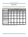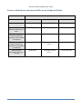
1
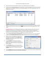
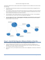
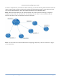
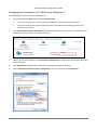
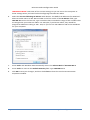
Ethernet Radio Configuration Guide for Gateway, Endpoint, and Repeater Radio Units April 20, 2015 Customer Service 1-866-294-5847 Baseline Inc. www.baselinesystems.com Phone 208-323-1634 FAX 208-323-1834 Toll Free 866-294-5847 ©2014 Baseline Inc. All Rights Reserved. Table of Contents Section 1 Configuring the Radios ................................................................................. 1 Before You Begin ...................................................................................................................... 1 Overview of the Steps .............................................................................................................. 1 Step 1 – Ask Your Network Administrator for LAN Network Settings ............................................ 2 Step 2 – Complete the Ethernet Radio Configuration Worksheet ................................................. 2 Step 3 – Install the Radio Equipment and Antennas ...................................................................... 2 Step 4 – Verify Radio Communication over the Stand-Alone Network .......................................... 3 Step 5 – Download the Discovery Server Executable to the Laptop Computer ............................. 3 Step 6 – Configure the Settings on the Ethernet Radios ................................................................ 3 Change the Default IP Address to the Static IP Address for the LAN ........................................ 3 Change Additional Radio Settings ............................................................................................ 5 Step 7 – Verify that the Controllers Are Connected to BaseManager............................................ 6 Section 2 Adding a Repeater ........................................................................................ 7 Overview of the Steps .............................................................................................................. 7 Step 1 – Map Out the Subnet IDs for the Network ........................................................................ 7 Step 2 – Install the Repeater Ethernet Radio at the Site................................................................ 8 Step 3 – Find the IP Addresses for the Radios ............................................................................... 9 Stand-Alone Network Instructions ........................................................................................... 9 Find the IP Address of the Repeater Ethernet Radio........................................................... 9 Change the Computer’s IP Address to Connect to the Stand-Alone Network ................... 10 Step 4 – Configure the Settings for the Endpoint that is Called through the Repeater................ 10 Step 5 – Configure the Settings for All Other Endpoints in the Network ..................................... 11 Step 6 – Configure the Settings for the Repeater ........................................................................ 12 Step 7 – Configure the Settings for the Gateway ......................................................................... 12 Step 8 – Verify that the Controllers Are Connected to BaseManager.......................................... 13 Section 3 Using the Configuration Web Server ...........................................................15 Connecting to the Configuration Web Server .............................................................................. 15 Ethernet Radio Settings Reference .............................................................................................. 16 IP Setup Settings .................................................................................................................... 16 IP Address / Subnet Mask / Default Gateway Fields ......................................................... 16 Page i Web Page Port .................................................................................................................. 16 Spanning Tree ................................................................................................................... 16 Save Your Changes............................................................................................................ 17 Radio Setup Settings .............................................................................................................. 17 Network Type ................................................................................................................... 17 Modem Mode ................................................................................................................... 17 Frequency Key .................................................................................................................. 18 Frequency Zones ............................................................................................................... 18 Network ID........................................................................................................................ 18 Repeaters.......................................................................................................................... 18 Subnet ID .......................................................................................................................... 18 Save Your Changes............................................................................................................ 20 Changing the Computer’s IP Address in Windows ....................................................................... 21 Changing the Computer’s IP Address in Windows XP............................................................. 21 Changing the Computer’s IP Address in Windows 7............................................................... 23 Appendix ....................................................................................................................25 Point-to-Multipoint Operation LEDs on Gateway and Repeater Radios ................................. 25 Point-to-Multipoint Operation LEDs on an Endpoint Radio ................................................... 26 Page ii FCC Compliance Information This equipment has been tested and found to comply with the limits for a Class B digital device, pursuant to part 15 of the FCC Rules. These limits are designed to provide reasonable protection against harmful interference in a residential installation. This equipment generates, uses and can radiate radio frequency energy, and if not installed and used in accordance with the instructions, may cause harmful interference to radio communications. However, there is no guarantee that interference will not occur in a particular installation. If this equipment does cause harmful interference to radio or television reception, which can be determined by turning the equipment off and on, the user is encouraged to try to correct the interference by one or more of the following measures: • • • • Reorient or relocate the receiving antenna. Increase the separation between the equipment and receiver. Connect the equipment into an outlet on a circuit different from that to which the receiver is connected. Consult the dealer or an experienced radio/TV technician for help. Page iii Ethernet Radio Configuration Guide Section 1 – Configuring the Radios Ethernet radios are a good solution for wireless communication at a large site with multiple controllers that do not have access to another type of Internet connection. Ethernet radios establish a wireless network across a large site, and all Baseline controllers can use this network to send and receive data. The typical configuration for a large site is one Gateway radio in its own enclosure and an Endpoint radio in each BaseStation controller. In cases where a controller does not have adequate signal strength to connect to the rest of the network, an additional Gateway radio can be configured as a Repeater to boost the signal to the outlying controller. Keep in mind, however, that using a Repeater will reduce the data speed on the network by 50 percent or more. After the network for the radios is set up and communicating, the Gateway radio unit is connected via Ethernet to the site’s local area network (LAN). Then, the radio network can send and receive data over the Internet. Before You Begin Baseline strongly recommends that a site survey is done before you order Ethernet radio equipment or install the components. Contact your Baseline representative to arrange a site survey. Overview of the Steps for Configuring the Radios To establish communication through your Ethernet radio network, you need to perform the following steps: Step 1 – Ask your network administrator for LAN network settings. Step 2 – Complete the Ethernet Radio Configuration Worksheet. Step 3 – Install the radio equipment and antennas. Step 4 – Verify that the radios are communicating with each other over the stand-alone network. Step 5 – Download the Discovery Server executable to the laptop computer. Step 6 – Configure the settings on the Ethernet radios. Step 7 – Verify that the controllers are connected to BaseManager. Section 1 – Configuring the Radios Page 1 Ethernet Radio Configuration Guide Step 1 – Ask Your Network Administrator for LAN Network Settings In order for Ethernet radios to communicate with each other, each radio unit must have a unique static IP (internet protocol) address assigned to it. Like the street address for your home, an IP address identifies the radios within a network. It helps traffic flow between the radios because each one has its own IP address. An IP address is formatted as a series of four values separated by periods. Example: 192.168.111.100 All Ethernet radio units shipped from Baseline are assigned default IP addresses. These default IP addresses allow the radios to communicate with each other over a stand-alone network during installation and setup. However, the radios cannot send and receive data over the Internet until you change the default IP addresses to IP addresses that are compatible with your local area network (LAN). Ask your network administrator to assign a range of static IP addresses for the Ethernet radios so that each radio will have a unique static IP address. Your network administrator needs to know how many radios need static IP addresses. However, you don’t need to identify the specific radios for the administrator because any IP address can be assigned to any radio unit. Also ask your network administrator for the Subnet Mask and Default Gateway (also known as the router IP address) for the LAN. Step 2 – Complete the Ethernet Radio Configuration Worksheet Use the information that you requested from your network administrator to complete the Ethernet Radio Configuration Worksheet (found in the Appendix of this document) for all of the radio equipment that will be used at your site. You will use the information from this worksheet to configure the radio settings in Step 6 of this section. Having this information available will make radio configuration quick and easy. Step 3 – Install the Radio Equipment and Antennas If the radios are ordered with the BaseStation controllers, the radios will be factory-installed in the BaseStation enclosures. If you ordered separate radio equipment, install the equipment according to the instructions in the installation guide. Make sure all antennas are properly installed. IMPORTANT! Make sure the antenna cable remains securely attached to the connector on the Ethernet radio. If the radio is powered up with a loose or disconnected antenna, damage may occur to the circuitry. This damage is not covered by warranty. Page 2 Section 1 – Configuring the Radios Ethernet Radio Configuration Guide Step 4 – Verify Radio Communication over the Stand-Alone Network All Ethernet radio units shipped from Baseline are assigned default IP addresses that will establish a stand-alone network during installation and setup. The stand-alone network enables you to verify that the radio units are communicating with each other before you connect them to the local area network (LAN) at the site. After all radio units have been installed and powered up, review the Status LEDs on the units. When the Endpoint has not linked with the Gateway, the ERR LED is solid bright red. Refer to the tables in the Appendix for a description of the LEDs. Step 5 – Download the Discovery Server Executable to the Laptop Computer To set up the Ethernet radios, you will need a laptop computer and an Ethernet cable. The laptop must have the Discovery Server executable file saved on it. If the laptop that you will be using to set up the radios is capable of being connected to the Internet, you can download the Discovery Server executable file from the Baseline web site and save the file to the laptop. If the laptop does not have Internet access, you will need to use another Internet-connected computer to save the executable file to a USB flash drive and then copy the file onto the laptop from the USB flash drive. URL for the Discovery Server Executable File http://baselinesystems.com/public_documents/Discovery_Server_v1.5.exe Save the Discovery Server executable file on the desktop or in a folder where it will be easy to find. Step 6 – Configure the Settings on the Ethernet Radios You will need the laptop computer that has the Discovery Server executable file and an Ethernet cable to perform this step. You will also need the information from the Ethernet Radio Configuration Worksheet (found in the Appendix of this document). The procedure below describes how to configure all the radios in your network while connected to the Gateway radio. Change the Default IP Address to the Static IP Address for the LAN 1. Go to the Gateway radio unit. Make sure that it is powered up. 2. Power up the laptop. 3. Open the enclosure door and plug one end of the Ethernet cable into the Ethernet port on the Gateway radio module. Section 1 – Configuring the Radios Page 3 Ethernet Radio Configuration Guide 4. Plug the other end of the Ethernet cable into an Ethernet port on the laptop. 5. Double-click the Discovery Server executable file, and then click Run in the Security Warning dialog box. The FreeWave Discovery Tool window displays a list of the radios that are on the stand-alone network. Note: The FreeWave Discovery Tool finds all radios that are connected to the radio network. Check the serial number before you select a radio to ensure that you configure the correct radio. IMPORTANT! When you change the IP address for a radio, it will drop from the list in the Discovery Tool because it is no longer part of the stand-alone network. Change the IP addresses for all of the Endpoint radios first in order to keep the Gateway radio in the list until you have finished changing the IP addresses for all other radio units. 6. Using the Ethernet Radio Setup Worksheet, find the serial number for one of the Endpoint radios in the FreeWave Discovery Tool window, and then click on the row to highlight it. 7. Right-click on the highlighted row and from the menu that displays, click Change Basic Settings. The Change Serial Number xxxxxxx dialog box displays. 8. In the IP Address field, type the static IP address that you recorded on the Ethernet Radio Setup Worksheet for the selected radio serial number. 9. In the Netmask field, type the LAN subnet mask that you recorded on the Ethernet Radio Setup Worksheet if it is different from the default. 10. In the Gateway field, type the LAN default Gateway (also known as the router IP address) that you recorded on the Ethernet Radio Setup Worksheet. Page 4 Section 1 – Configuring the Radios Ethernet Radio Configuration Guide Note: This Gateway field is the IP address of the gateway of the site network (typically the IP address of the router for the site network), not the IP address of the Gateway radio. All radio units, including the Gateway radio, must point to the gateway address for proper operation. 11. Leave the default entry in the Web Port field. 12. In the Password field, type admin, and then click the Change button. 13. Repeat steps 6 – 12 for each radio listed in the FreeWave Discovery Tool window. 14. After you have changed the IP address for the Gateway radio, click the Search button to find the radios based on their new configuration. Check the list to verify that all radios in your network show up with the correct configuration. 15. Click the Exit button to close the FreeWave Discovery Tool. 16. Disconnect the Ethernet cable from the laptop, and then plug the Ethernet cable from the Gateway radio into a live Ethernet jack for the LAN at the site. Change Additional Radio Settings You can change additional settings on the Ethernet radio using the FreeWave configuration web server. In the Radio Setup option on the configuration web server, you can set the radio’s mode to Gateway, Repeater, or Endpoint. You can also enable the Repeaters setting if you need to add a Repeater to your radio network. When you add a Repeater, you’ll need to configure the Subnet ID settings for all your radios in the configuration web server. Refer to Section 3 on page 15 of this document to find out how to log into the configuration web server and to learn about the settings. Only those fields that you need to verify and/or change are mentioned in Section 3. We recommend leaving the default settings in all other fields. If you need more information about the fields and settings, refer to the FreeWave Ethernet Radio User Manual found on Baseline’s web site: http://www.baselinesystems.com/mediafiles//pdf/Freewave_Ethernet_Radio_User_Manual.pdf Section 1 – Configuring the Radios Page 5 Ethernet Radio Configuration Guide Step 7 – Verify that the Controllers Are Connected to BaseManager Depending on how the network is configured at the site, the network administrator may need to set up port forwarding in a router and/or change firewall settings in order to allow the radio network to send and receive data over the Internet. 1. Go to one of the Baseline controllers that has a radio Endpoint installed. 2. Go into the network settings on the controller to ensure that it is using an Ethernet connection. Even though the radio in the controller is set to a static IP address, the controller itself should continue to use DHCP to obtain an IP address from the server. Note: In some cases, a network administrator may want the controller to have a static IP address. If you need to configure this, refer to Setting Up a Static IP Address in the controller’s user manual. 3. The controller displays an activation PIN. Write down the PIN. 4. You can add these controllers to your BaseManager account using the Admin tool in BaseManager. If you do not have a BaseManager account, call Baseline to set one up. (Baseline Support 866.294.5847) Page 6 Section 1 – Configuring the Radios Ethernet Radio Configuration Guide Section 2 – Adding a Repeater This section describes the configuration changes required to add a Repeater radio unit to an Ethernet radio network. It assumes that you have already installed your Gateway radio unit and your Endpoint radio units. Overview of the Steps for Adding a Repeater To add a Repeater to your Ethernet radio network, you need to perform the following steps: Step 1 – Map out the subnet IDs for the network. Step 2 – Install the Repeater Ethernet radio at the site. Step 3 – Find the IP addresses for the radios. Step 4 – Configure the settings for the Endpoint that is called through the repeater. Step 5 – Configure the settings for all other Endpoints in the network. Step 6 – Configure the settings for the Repeater. Step 7 – Configure the settings for the Gateway. Step 8 – Verify that the controllers are connected to BaseManager. Step 1 – Map Out the Subnet IDs for the Network When you add a Repeater to an Ethernet radio network, you need to assign the RX (receive) and TX (transmit) Subnet IDs to each of the radios to force the communications to follow a specific path. You will assign the Subnet IDs in a later step of this process, but it’s best to have a mental image of how the network is laid out and how the Subnet IDs need to be assigned before you start configuring the radios. You might even want to sketch a map of the network and define the Subnet IDs, so you’ll be able to easily configure them in the radios. We recommend that you record the serial numbers and IP addresses for all radios on your map so you are certain to make changes to the correct radio in the configuration server. The valid values for the Subnet IDs are any number between 0 and 9 or any letter between A and F. While these values don’t have intrinsic meanings, it might be helpful to think of 0 as the identifier for the Gateway and F as “final,” which indicates that the device is final in the line. Section 2 – Adding a Repeater Page 7 Ethernet Radio Configuration Guide The example below shows a radio network where a Repeater has been added to one branch. Note the following: • The values for the RX and TX Subnet IDs on the Gateway radio have been changed from the default of F to 0. • On all Endpoint radios that receive and transmit directly to the Gateway have their RX Subnet IDs set to 0, which tells them to “listen” to the Gateway, and their TX Subnet IDs are set to F, which indicates that the device is the final in the line. • On the Repeater radio, the RX Subnet ID is set to 0, which tells it to “listen” to the Gateway. The TX Subnet ID is set to 1, which serves to identify the Repeater. • On the Endpoint radio that is called through the Repeater, the RX Subnet ID is set to 1, which tells that Endpoint to “listen” to the Repeater. The TX Subnet ID is set to F, which indicates that the device is final in the line. Step 2 – Install the Repeater Ethernet Radio at the Site There are two options for adding a Repeater to an existing Ethernet radio network: • Install a Gateway Ethernet radio unit in its own enclosure, and then reconfigure it as a Repeater. In this case, install the enclosure according to the instructions that came with the unit, and then continue to Step 3 in this section. • Reconfigure one of your Endpoint Ethernet radio units as a Repeater. In this case, continue to Step 3. Page 8 Section 2 – Adding a Repeater Ethernet Radio Configuration Guide Step 3 – Find the IP Addresses for the Radios First, determine what network the Ethernet radios are connected to: • Newly installed Ethernet radios might still be configured for the default stand-alone network (based on the IP addresses that were assigned at the factory). Find the IP addresses for your radios by following the instructions in the Stand-Alone Network section below. • Ethernet radios might be configured to connect to the local area network (LAN) at the site (based on the IP addresses that were assigned by the site network administrator). If your Ethernet radio network is connected to the LAN, use the information recorded on the Ethernet Radio Configuration Worksheet to find the static IP addresses for all of the radio equipment. Stand-Alone Network Instructions To configure the radio settings, you will need a laptop computer with the Discovery Server executable and an Ethernet cable. If you need to download the Discovery Server executable onto the laptop, refer to Step 5 of Configuring the Radios on page 3 of this document. Find the IP Address of the Repeater Ethernet Radio 1. Go to the Repeater radio unit. Make sure that it is powered up. 2. Write down the serial number of the Repeater radio unit. You’ll find the number on a sticker affixed to the radio hardware. 3. Power up the laptop. 4. Open the enclosure door and plug one end of the Ethernet cable into the Ethernet port on the Repeater radio module. 5. Plug the other end of the Ethernet cable into an Ethernet port on the laptop. 6. Double-click the Discovery Server executable file, and then click Run in the Security Warning dialog box. The FreeWave Discovery Tool window displays a list of the radios that are on the stand-alone network. Section 2 – Adding a Repeater Page 9 Ethernet Radio Configuration Guide Note: The FreeWave Discovery Tool finds all radios that are connected to the radio network. Check the serial number before you select a radio to ensure that you configure the correct radio. 7. Find the serial number of the Repeater radio unit in the list and then write down the IP address that is assigned to it. Change the Computer’s IP Address to Connect to the Stand-Alone Network Refer to “Changing the Computer’s IP Address in Windows” on page 21 of this document for instructions. Be sure to follow the instructions for version of Windows that is running on the laptop. Step 4 – Configure the Settings for the Endpoint that is Called through the Repeater Configure the settings on the radio units in the order given in the following sections. If you configure in another order, the radios may stop communicating with each other and you won’t be able to find them in the configuration server. If this happens, you will need to connect the laptop to the radio with an Ethernet cable and use the direct connection to configure the radio. 1. Start the web browser software (Internet Explorer, Firefox, or Chrome) on the computer. 2. In the Address Bar at the top of the web browser window, type the IP address for the Endpoint radio that is called through the Endpoint radio unit, and then press Enter. If the browser indicates that it is switching to a secure connection, you may need to click in a message box to continue. 3. In the security dialog box, type admin in both the Username and Password fields, and then click OK. The FreeWave configuration web server displays. 4. Verify that the serial number at the top of the page matches the serial number of the Endpoint radio that is called through the Repeater. If it does not, make sure that the IP address in the Address Bar at the top of the web browser window is accurate for that radio. If necessary, type a different IP address in the Address Bar, and then press Enter. 5. In the menu on the left, click the Radio Setup option. 6. Make sure that the Network Type field is set to Multi-Point. 7. Click the drop-down arrow in the Modem Mode field, and select Endpoint from the list. Note: When configuring an Endpoint, leave the Repeaters field set to Disabled. You only need to enable this setting in the Gateway radio’s configuration. 8. Scroll to the bottom of the Radio Setup page, and then click the drop-down arrow in the Subnet ID (RX) field. Select an option from the list. Note: Refer to the network map that you made and use the settings that you assigned. 9. Click the drop-down arrow in the Subnet ID (TX) field. Select an option from the list. 10. Click the Save/Apply button. Page 10 Section 2 – Adding a Repeater Ethernet Radio Configuration Guide 11. Click the Reboot button. Note: If your changes don’t show up in the configuration pages after clicking the Save/Apply button and rebooting the Ethernet radio, you might need to power cycle the radio. Unplug the power connector from the control board. Wait a few seconds and then plug the power connector back in. Step 5 – Configure the Settings for All Other Endpoints in the Network 1. Start the web browser software (Internet Explorer, Firefox, or Chrome) on the computer. 2. In the Address Bar at the top of the web browser window, type the IP address for one of the Endpoint radios that is NOT called through the Repeater radio unit, and then press Enter. If the browser indicates that it is switching to a secure connection, you may need to click in a message box to continue. 3. In the security dialog box, type admin in both the Username and Password fields, and then click OK. The FreeWave configuration web server displays. 4. Verify that the serial number at the top of the page matches the serial number of the Endpoint radio. If it does not, make sure that the IP address in the Address Bar at the top of the web browser window is accurate for that radio. If necessary, type a different IP address in the Address Bar, and then press Enter. 5. In the menu on the left, click the Radio Setup option. 6. Make sure that the Network Type field is set to Multi-Point. 7. Click the drop-down arrow in the Modem Mode field, and select Endpoint from the list. Note: When configuring an Endpoint, leave the Repeaters field set to Disabled. You only need to enable this setting in the Gateway radio’s configuration. 8. Scroll to the bottom of the Radio Setup page, and then click the drop-down arrow in the Subnet ID (RX) field. Select an option from the list. Note: Refer to the network map that you made and use the settings that you assigned. 9. Click the drop-down arrow in the Subnet ID (TX) field. Select an option from the list. 10. Click the Save/Apply button. 11. Click the Reboot button. Note: If your changes don’t show up in the configuration pages after clicking the Save/Apply button and rebooting the Ethernet radio, you might need to power cycle the radio. Unplug the power connector from the control board. Wait a few seconds and then plug the power connector back in. 12. Repeat the steps in this task for all Endpoint radios in the network. Section 2 – Adding a Repeater Page 11 Ethernet Radio Configuration Guide Step 6 – Configure the Settings for the Repeater 1. Start the web browser software (Internet Explorer, Firefox, or Chrome) on the computer. 2. Type the IP address for the Repeater radio unit in the Address Bar at the top of the web browser window, and then press Enter. If the browser indicates that it is switching to a secure connection, you may need to click in a message box to continue. 3. In the security dialog box, type admin in both the Username and Password fields, and then click OK. The FreeWave configuration web server displays. 4. Verify that the serial number at the top of the page matches the serial number of the Repeater radio. If it does not, make sure that the IP address in the Address Bar at the top of the web browser window is accurate for that radio. If necessary, type a different IP address in the Address Bar, and then press Enter. 5. In the menu on the left, click the Radio Setup option. 6. Make sure that the Network Type field is set to Multi-Point. 7. Click the drop-down arrow in the Modem Mode field, and select Repeater from the list. Note: When configuring the Repeater, leave the Repeaters field set to Disabled. You only need to enable this setting in the Gateway radio’s configuration. 8. Scroll to the bottom of the Radio Setup page, and then click the drop-down arrow in the Subnet ID (RX) field. Select an option from the list. Note: Refer to the network map that you made and use the settings that you assigned. 9. Click the drop-down arrow in the Subnet ID (TX) field. Select an option from the list. 10. Click the Save/Apply button. 11. Click the Reboot button. Note: If your changes don’t show up in the configuration pages after clicking the Save/Apply button and rebooting the Ethernet radio, you might need to power cycle the radio. Unplug the power connector from the control board. Wait a few seconds and then plug the power connector back in. Step 7 – Configure the Settings for the Gateway 1. Start the web browser software (Internet Explorer, Firefox, or Chrome) on the computer. 2. Type the IP address for the Gateway radio unit in the Address Bar at the top of the web browser window, and then press Enter. If the browser indicates that it is switching to a secure connection, you may need to click in a message box to continue. 3. In the security dialog box, type admin in both the Username and Password fields, and then click OK. The FreeWave configuration web server displays. Page 12 Section 2 – Adding a Repeater Ethernet Radio Configuration Guide 4. Verify that the serial number at the top of the page matches the serial number of the Gateway radio. If it does not, make sure that the IP address in the Address Bar at the top of the web browser window is accurate for that radio. If necessary, type a different IP address in the Address Bar, and then press Enter. 5. In the menu on the left, click the Radio Setup option. 6. Make sure that the Network Type field is set to Multi-Point. 7. Click the drop-down arrow in the Modem Mode field, and select Gateway from the list. 8. Scroll to the bottom of the Radio Setup page, and then click the drop-down arrow in the Repeaters field. Select Enabled. 9. Click the drop-down arrow in the Subnet ID (RX) field. Select an option from the list. Note: Refer to the network map that you made and use the settings that you assigned. 10. Click the drop-down arrow in the Subnet ID (TX) field. Select an option from the list. 11. Click the Save/Apply button. 12. Click the Reboot button. Note: If your changes don’t show up in the configuration pages after clicking the Save/Apply button and rebooting the Ethernet radio, you might need to power cycle the radio. Unplug the power connector from the control board. Wait a few seconds and then plug the power connector back in. 13. Close the browser window to close the configuration web server. 14. If your laptop is directly connected to one of the radios, unplug the Ethernet cable. Reconnect the cross-over cable between the Ethernet radio and the controller if necessary. 15. If you configured the laptop’s IP address to connect to the Ethernet radio network, return the laptop to the original settings. Step 8 – Verify that the Controllers Are Connected to BaseManager Depending on how the network is configured at the site, the network administrator may need to set up port forwarding in a router and/or change firewall settings in order to allow the radio network to send and receive data over the Internet. 1. Go to one of the Baseline controllers that has a radio Endpoint installed. 2. Go into the network settings on the controller to ensure that it is using an Ethernet connection. Even though the radio in the controller is set to a static IP address, the controller itself should continue to use DHCP to obtain an IP address from the server. Note: In some cases, a network administrator may want the controller to have a static IP address. If you need to configure this, refer to Setting Up a Static IP Address in the controller’s user manual. Section 2 – Adding a Repeater Page 13 Ethernet Radio Configuration Guide 3. The controller displays an activation PIN. Write down the PIN. 4. You can add these controllers to your BaseManager account using the Admin tool in BaseManager. If you do not have a BaseManager account, call Baseline to set one up. (Baseline Support 866.294.5847) Page 14 Section 2 – Adding a Repeater Ethernet Radio Configuration Guide Section 3 – Using the Configuration Web Server After you have installed your Ethernet Radio network and completed the basic configuration steps outlined in Configuring the Radios, you can use the FreeWave configuration web server to change the settings on Baseline’s Ethernet radios. IMPORTANT! Before you use the instructions in this section, you must have the following information: • The IP addresses of the Ethernet radios that you want to change the settings for – refer to the Ethernet Radio Setup Worksheet. • Know whether your Ethernet radios are using the default stand-alone network settings or they are connected to a local network. For Ethernet radios that are using the default stand-alone network settings, you must change the IP setting on your computer to connect to the same network. Refer to the following sections in this document depending on which Microsoft Windows operating system is running on your computer: Changing the Computer’s IP Address in Windows XP on page 21 Changing the Computer’s IP Address in Windows 7 on page 23 For Ethernet radio networks that are connected to a local network, make sure that your computer is also connected to the same network. Connecting to the Configuration Web Server 1. Using a computer that is connected to the same network as the radios, start the web browser software (Internet Explorer, Firefox, or Chrome). 2. Using the Ethernet Radio Setup Worksheet, find the static IP address that is assigned to the radio unit that you want to change the settings for. Type that IP address in the Address Bar at the top of the web browser window, and then press Enter. If the browser indicates that it is switching to a secure connection, you may need to click in a message box to continue. 3. In the security dialog box, type admin in both the Username and Password fields, and then click OK. The FreeWave configuration web server displays. 4. Verify that the serial number at the top of the page matches the serial number of the Ethernet radio that you want to change settings for. If it does not, make sure that the IP address in the Address Bar at the top of the web browser window is accurate for that radio. If necessary, type a different IP address in the Address Bar, and then press Enter. Section 3 – Using the Configuration Web Server Page 15 Ethernet Radio Configuration Guide Ethernet Radio Settings Reference Only those fields that you need to verify and/or change are mentioned in this reference. We recommend leaving the default settings in all other fields. If you need more information about the fields and settings, refer to the FreeWave User Manual found on Baseline’s web site at the following URL: http://www.baselinesystems.com/mediafiles/pdf/Freewave_Ethernet_Radio_User_Manual.pdf IP Setup Settings In the FreeWave configuration web server, click the IP Setup option in the left navigation pane to modify the IP settings that allow the Ethernet radio to connect to the LAN at the installation site. These settings are the same as those that can be configured through the FreeWave Discovery Tool. If you have already configured the IP settings for your Ethernet radios in the FreeWave Discovery Tool, you probably don’t need to make changes on this page in the configuration web server. However, the fields on the IP Setup page are described below for reference. Remember that the IP settings allow the Ethernet radio to connect to the Internet, so use care when making changes to these settings. IP Address / Subnet Mask / Default Gateway Fields Each Ethernet radio unit must be assigned a unique IP address. The IP addresses must be in the proper subnet. Ask your network administrator for a range of IP addresses for the radios. Your network administrator also needs to provide the Subnet Mask and Default Gateway. Note: Putting multiple devices on the network with the same IP address can cause the whole network to crash. Web Page Port Use the Web Page Port setting to change the assigned port for the Web interface setup pages. The default setting is port 80, which is the standard Web page port. If you change this setting from port 80, you must include the proper port number when accessing the setup pages. For example: http://<IP address>:<Port> Where <IP address> is the IP address of the Ethernet radio unit, and <Port> is the port number assigned in the IP Setup page. Any valid TCP port can be entered from 1 to 65535. If an invalid TCP port is entered, the Ethernet radio unit will default the Web Page Port setting to 80. Spanning Tree Checking the Enable box will cause a Gateway radio to use Spanning Tree Protocol (IEEE 802.1D). This will eliminate the possibility of the radios creating a network loop, which can cause networkwide problems. Spanning Tree Protocol does use radio bandwidth because any Spanning Tree radios are constantly communicating their network “location.” FreeWave Technologies recommends leaving Spanning Tree unchecked, unless Spanning Tree Protocol is required by your application. Page 16 Section 3 – Using the Configuration Web Server Ethernet Radio Configuration Guide Save Your Changes Click the Save/Apply button at the bottom of the web page. In some cases, the radio may need to be rebooted in order for the changes to take effect. When the reboot is necessary, the web page displays a message and a link to send the reboot command to the radio. Note: If your changes don’t show up in the configuration pages after clicking the Save/Apply button and rebooting the Ethernet radio, you might need to power cycle the radio. Unplug the power connector from the control board. Wait a few seconds and then plug the power connector back in. When you have finished making changes to the Ethernet radio configuration, close the browser window for the FreeWave configuration web site. Radio Setup Settings In the FreeWave configuration web server, click the Radio Setup option in the left navigation pane to configure the general settings on the Ethernet radio. Network Type Configure the Network Type to Multi-Point for all Baseline Ethernet Radio units in your network. Modem Mode In the Modem Mode field, configure the setting for each radio according to its function within the network. For example, make sure the Modem Mode field for the Gateway radio is set to Gateway. When you are setting up Repeaters or Endpoints, make sure this field matches the function of the unit. Section 3 – Using the Configuration Web Server Page 17 Ethernet Radio Configuration Guide Frequency Key By default, the Frequency Key field is set to B. Only change this setting if you need to minimize the interference with other FreeWave transceivers operating in the area. Keep in mind that all radios in a network need to be set to the same Frequency Key. IMPORTANT! Radios with mismatched Frequency Key settings will connect to each other, but will not reliably transfer data. Frequency Zones The idea of frequency zoning is to divide the available band (902 MHz to 928 MHz) into smaller bands—in this case 16 smaller bands each consisting of 7 or 8 frequency channels. These 16 Zones are listed in the Frequency Zones section of the Radio Setup page. A checkmark indicates that zone will be used by the radio. A blank box indicates the radio will not use those frequencies. The zones listed are in MHz. The radio requires at least one zone active to operate. If all Frequency Zones are de-selected, the radio will operate as if all zones were selected. Any Endpoint or Endpoint/Repeater radios will take their Frequency Zone settings from the Gateway radio, regardless of Network Type. Therefore, this setting can only be changed on the Gateway radio. Network ID By default, the Network ID field is set to 1634. You can change this setting if you want your Network ID to be different from other Baseline-supplied FreeWave radio networks operating in the area. Keep in mind that all radios in a network need to be set to the same Network ID. Repeaters In a Multi-Point network, it is critical to transmission timing to configure this parameter correctly. Be sure to keep this field disabled when there are no Repeaters in your network because when the field is selected, it can impact your network speed. If there is a Repeater in your radio network, set the Repeaters field to Enabled in the Gateway radio only. Subnet ID In a Multi-Point network with a Subnet ID of RX=F and TX=F, an Endpoint or Repeater will connect with the first Repeater or Gateway that it hears with the same Network ID. There are scenarios, however, where communications need to be forced to follow a specific path. The valid values for these fields are any number between 0 and 9 or any letter between A and F. If your Ethernet radio network consists of a Gateway and an Endpoint (or any number of Endpoints), and you do not have a Repeater, leave the Subnet ID (RX) and the Subnet ID (TX) fields set to the default of F. • Subnet ID (RX): (Receive) This setting identifies which transceiver a Repeater or Endpoint will listen to. • Subnet ID (TX): (Transmit) This setting identifies the ID on which this device transmits, and, in turn, which devices will listen to it. The Subnet ID (TX) parameter is relevant for Multi-Point Gateways and Repeaters only. Page 18 Section 3 – Using the Configuration Web Server Ethernet Radio Configuration Guide If there is a Repeater in your Ethernet radio network, you need to identify how the devices talk and listen to each other and then configure the Subnet ID fields appropriately for each Ethernet radio unit. In the example below, notice the Subnet ID values for the individual radios. Note: While the valid values for the Subnet ID fields don’t have intrinsic meanings, it might be helpful to think of 0 as the identifier for the Gateway and F as “final,” which indicates that the device is the final in the line and does not use a subnet ID. Note: For help with the tasks associated with configuring a Repeater, refer to Section 2 on page 7 of this document. Section 3 – Using the Configuration Web Server Page 19 Ethernet Radio Configuration Guide Save Your Changes Click the Save/Apply button at the bottom of the web page. In some cases, the radio may need to be rebooted in order for the changes to take effect. When the reboot is necessary, the web page displays a message and a link to send the reboot command to the radio. Note: If your changes don’t show up in the configuration pages, after clicking the Save/Apply button and rebooting the Ethernet radio, you might need to power cycle the radio. Unplug the power connector from the control board. Wait a few seconds and then plug the power connector back in. When you have finished making changes to the Ethernet radio configuration, close the browser window for the FreeWave configuration web page. Page 20 Section 3 – Using the Configuration Web Server Ethernet Radio Configuration Guide Changing the Computer’s IP Address in Windows The following information explains how to change the IP address of your computer in Windows XP and in Windows 7.0. Changing the Computer’s IP Address in Windows XP The following instructions are for Windows XP. 1. From the Windows Start menu, click Control Panel or Settings > Control Panel. 2. Double-click the Network Connections icon. 3. Right-click Local Area Connection and select Properties to display the Local Area Connection Properties window. Note: Depending on the Network setup, different icons may appear here. Contact your IT Department if you cannot find the proper icon. Section 3 – Using the Configuration Web Server Page 21 Ethernet Radio Configuration Guide 5. Click Internet Protocol (TCP/IP) to highlight it, and then click Properties to display the Internet Protocol (TCP/IP) Properties window. IMPORTANT NOTE! Take note of the current settings so you can return the computer to those settings when you have finished configuring the Ethernet radios. 6. Click the Use the following IP address radio button. The default IP addresses for Baseline’s Ethernet radios starts at 192.168.111.100. In the first 3 cells of the IP address field, type 192.168.111 and in the last cell, type a number that is outside the range of the default IP addresses that are assigned to your Ethernet radios. For example, if you have 4 radios, they would be assigned IP addresses ending in 100 - 104, so you can use 192.168.111.105 as the IP address for your computer. 7. Press <Tab> and Windows XP automatically enters the Subnet Mask of 255.255.255.0. 8. Press <Tab> to move to the Default Gateway field. Type 192.168.111.1 9. Click OK to save your changes, and then click Close to close the Local Area Connection Properties window. Page 22 Section 3 – Using the Configuration Web Server Ethernet Radio Configuration Guide Changing the Computer’s IP Address in Windows 7 The following instructions are for Windows 7.0. 1. From the Windows Start menu, select Control Panel. If you are viewing the Control Panel by Categories, click Network and Internet. If you are viewing the Control Panel by icons, click Network and Sharing Center and continue with step 2. 2. Click View network status and tasks in the Network Sharing Center group. The middle of the displayed screens shows your active networks. 3. Within your active networks, click Local Area Connection to display the Local Area Connection Status window. 4. Click Properties to display the Local Area Connection Properties window. 5. Select Internet Protocol Version 4 (TCP/IPv4) in the list, and then click Properties. Section 3 – Using the Configuration Web Server Page 23 Ethernet Radio Configuration Guide IMPORTANT NOTE! Take note of the current settings so you can return the computer to those settings when you have finished configuring the Ethernet radios. 6. Select the Use the following IP address radio button. The default IP addresses for Baseline’s Ethernet radios starts at 192.168.111.100. In the first 3 cells of the IP address field, type 192.168.111 and in the last cell, type a number that is outside the range of the numbers that are assigned to your Ethernet radios. For example, if you have 4 radios, they would be assigned IP addresses ending in 100 - 104, so you can use 192.168.111.105 as the IP address for your computer. 7. Press <Tab> and Windows XP automatically enters the Subnet Mask of 255.255.255.0. 8. Press <Tab> to move to the Default Gateway field. Type 192.168.111.1 9. Click OK to save your changes, and then click Close to close the Local Area Connection Properties window. Page 24 Section 3 – Using the Configuration Web Server Ethernet Radio Configuration Guide Appendix Point-to-Multipoint Operation LEDs on Gateway and Repeater Radios Radio Operation LEDs Gateway Condition Transmit (TX) Solid red dim* Clear to Carrier Transmit Send (CTS) Detect (CD) (TX) Off * Solid red Off * bright* Clear to Send (CTS) Blinking red Θ Repeater and Endpoint Solid red linked to Gateway, no bright* data Solid red dim* Off * Solid green* Solid red dim* * Solid red bright* Repeater and Endpoint Solid red linked to Gateway, bright* Gateway sending data to Endpoint Solid red dim* Off * Solid green* Solid red dim* * Solid red bright* Repeater and Endpoint Solid Solid red linked to Gateway, green* RCV dim* Endpoint sending data data to Gateway or Solid red bright* Intermittent Solid flash green* red »o« Solid red bright* * Solid red bright* Gateway with diagnostics program running Intermittent Solid flash green* red »o« Solid red bright* * Solid red bright* Powered, not linked Carrier Detect (CD) Solid red bright* Repeater Solid red bright* Solid red dim* * The Clear to Send (CTS) LED will be solid red* with a solid link. As the link weakens, the Clear to Send LED light on the Repeater and Endpoint will begin to flash Θ. Appendix Page 25 Ethernet Radio Configuration Guide Point-to-Multipoint Operation LEDs on an Endpoint Radio Radio Operation LEDs Condition Carrier Detect (CD) Transmit (TX) Clear to Send (CTS) Powered, not linked Solid red bright* Off * Blinking red Repeater and Endpoint linked to Gateway, no data Solid green* Off * * Solid red bright* Repeater and Endpoint linked to Gateway, Gateway sending data to Endpoint Solid green* Off * * Solid red bright* Repeater and Endpoint linked to Gateway, Endpoint sending data to Gateway Solid green* Intermittent flash red »o« * Solid red bright* Gateway with diagnostics program running Solid green* Intermittent flash red »o« * Solid red bright* Page 26 Appendix Ethernet Radio Configuration Guide Ethernet Radio Installation and Configuration Notes Appendix Page 27 Ethernet Radio Configuration Guide Radio Serial Number Description Static IP Address Gateway ____ . ____ . ____ . ____ Endpoint 1 ____ . ____ . ____ . ____ Endpoint 2 ____ . ____ . ____ . ____ Endpoint 3 ____ . ____ . ____ . ____ Endpoint 4 ____ . ____ . ____ . ____ Endpoint 5 ____ . ____ . ____ . ____ Endpoint 6 ____ . ____ . ____ . ____ Endpoint 7 ____ . ____ . ____ . ____ Endpoint 8 ____ . ____ . ____ . ____ Endpoint 9 ____ . ____ . ____ . ____ Endpoint 10 ____ . ____ . ____ . ____ Endpoint 11 ____ . ____ . ____ . ____ Endpoint 12 ____ . ____ . ____ . ____ Endpoint 13 ____ . ____ . ____ . ____ Endpoint 14 ____ . ____ . ____ . ____ Endpoint 15 ____ . ____ . ____ . ____ Endpoint 16 ____ . ____ . ____ . ____ Endpoint 17 ____ . ____ . ____ . ____ Endpoint 18 ____ . ____ . ____ . ____ Endpoint 19 ____ . ____ . ____ . ____ Endpoint 20 ____ . ____ . ____ . ____ Repeater ____ . ____ . ____ . ____ Page 28 Appendix Ethernet Radio Configuration Guide Netmask (Subnet Mask) Gateway (Router IP Address) ____ . ____ . ____ . ____ ____ . ____ . ____ . ____ ____ . ____ . ____ . ____ ____ . ____ . ____ . ____ ____ . ____ . ____ . ____ ____ . ____ . ____ . ____ ____ . ____ . ____ . ____ ____ . ____ . ____ . ____ ____ . ____ . ____ . ____ ____ . ____ . ____ . ____ ____ . ____ . ____ . ____ ____ . ____ . ____ . ____ ____ . ____ . ____ . ____ ____ . ____ . ____ . ____ ____ . ____ . ____ . ____ ____ . ____ . ____ . ____ ____ . ____ . ____ . ____ ____ . ____ . ____ . ____ ____ . ____ . ____ . ____ ____ . ____ . ____ . ____ ____ . ____ . ____ . ____ ____ . ____ . ____ . ____ ____ . ____ . ____ . ____ ____ . ____ . ____ . ____ ____ . ____ . ____ . ____ ____ . ____ . ____ . ____ ____ . ____ . ____ . ____ ____ . ____ . ____ . ____ ____ . ____ . ____ . ____ ____ . ____ . ____ . ____ ____ . ____ . ____ . ____ ____ . ____ . ____ . ____ ____ . ____ . ____ . ____ ____ . ____ . ____ . ____ ____ . ____ . ____ . ____ ____ . ____ . ____ . ____ ____ . ____ . ____ . ____ ____ . ____ . ____ . ____ ____ . ____ . ____ . ____ ____ . ____ . ____ . ____ ____ . ____ . ____ . ____ ____ . ____ . ____ . ____ ____ . ____ . ____ . ____ ____ . ____ . ____ . ____ Appendix Network ID Page 29