1
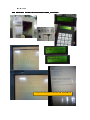
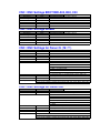
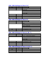
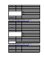
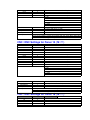
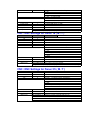
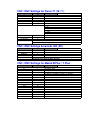
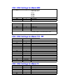
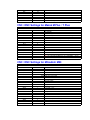
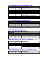
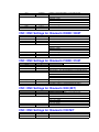
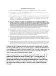
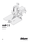
USB Reader Link Ⓡ Introduce & Manual
USB Reader Link
Ⓡ Kit easy down/upload data transmission between USB Reader LinkⓇ Kt
1) USB Reader Link can be set 5 remote for 5 controller system
2) USB Reader Link
Ⓡ Kit 5 remote SETUP are separate setting
3) USB Reader Link can be set separate setting by user for each machine, one for Brother, one for Fanuc
one for Mazak, one for Mitsubishi or etc.
4) USB Reader Link
5) USB Reader Link
Ⓡ can be set for data transmission PLC etc.
Ⓡ DNC or TAPE run
6) USB Reader Linnk
Ⓡ
available for Brother Tapping Center all data down/Upload to easy for maintenance team
5 Remote switch available
USB Reader LinkⓇ unit has the following feature :
- Work with just about any USB flash drive up to 4GB (1 GB include)
- Battery opeated (4AA NiMh rechargeable battery include)
- Full charged unit can continueusly operate 8+ hour
- For permanent hookup use charge only (include)
- User friendly interface with 2 line LCD display and 20 key keypad. Keypad symbols can be "rotated' for full
character set.
- Baud rate values : 300 to 115.2k
- Xon/Xoff, CTS/RTS, MZK protocols
- Up to 5 user defined and named setups, easily selectable before sending.receiving
- Real time clock stamps received files with current date on the USB flash drive
- File size and last modified date display before sending
- User can also 'peek' into start of the file before sending to see the program number/comment
- Drip deef if control is capable via RS232 port
- Include :
- USB Reader Link
- AA NiMh rechargeable batteries (4pcs)
- 110vac wall-plug charge
- USB 1GB flash memory
- RJ45 TO DB25M connector
- 6 feet cable
USB Reader KitⓇ with Brother Tapping Center TC-S2A, A00 Control
Ⓡ and open file
Compare after download to USB Reader Kit
USB Reader Link Ⓡ Introduce & Manual
USB Reader Link ® Quick Start Guide
1)
There is a User Manual in PDF format on the enclosed USB memory stick - please, read that first.
2)
Insert a USB memory stick into the USB Reader Link ® unit. Remove the small pink plastic stop from the
USB Reader Link ® unit On/Off switch and turn the unit on.
3)
After a couple of seconds the USB Reader Link ® will di
splay its main menu. Press 4 for SETUP. Follow the
instructions in the User Manual to set and name the first machine. Hint: make sure to match the machine’s baud
rate. For 90% of the controls ISO code, LF only and XON/XOFF handshake will work fine. At the
end press the ENT key to get back to the Main Menu.
4)
Select 2 for a Machine to USB transfer. Select the single dot, press ENT and name the incoming file for
simplicity 123 and press ENT (read the User Manual how to ‘rotate’ for letters) at the end press ENT again.
The USB Reader Link ® unit is now ready to
receive a file. Now perform a ‘Send’ or ‘Punch’ operation at the
machine tool. As the G code program is being sent, the second line of the USB Reader Link ® unit’s LCD
display shows the incoming lines. Once the transfer ends, the LCD display will show the last received
characters (LF signals line feed and CR signals carriage return characters.). Press ESC key to display the
name and number of characters of the just received program then press ESC again.
5) Now at the CNC control rename the just punched program and set the control to receive. Once ready, on
the USB Reader Link ® unit at the Main Menu select ite
m 1), arrow down to the just received 123 program
and press ENT key. The second line of the LCD display will show the outgoing lines. Once done your CNC
control should have and display the just received program. You can also take program 123 on the USB
memory stick to your computer and view/edit it for example with Notepad.
6)
Based on this experience now you can set up the rest of the machines. The similar machines can use the
same setup of the USB Reader Link ® unit. You can name a setup in the unit (Brother, FANUC, MAZAK, etc…) up
to 8 characters long. Before sending/receiving while at the Main Menu you can select a different setup using
the LIST and the arrow keys.
7)
The USB Reader Link ® can also drip
feed a CNC control if the control itself is capable of doing that. For
that application an USB Reader Link ® per machine is recommended with a permanent hookup. For a
permanent hookup you may remove the 4 AA batteries and connect the USB Reader Link ® to its charger all
the time.
While in the SETUP menu normally the setup is for viewing only. To enable
the change of BAUD rate, etc.. you need to type in - while in the SETUP menu
- the numbers 147 blindly. This code ‘unlocks’ the ‘view only’ mode. Once you leave the SETUP
menu and re-enter it you need t
This is to prevent accidental parameter change.
If the rechargeable battery is completely depleted, the LCD screen will show
nothing after turning the unit on. In such a case: 1) Turn the unit OFF.
Connect the charger for about 5 minutes.
2)
3) Turn the unit ON - display
should come back and the red charge light should turn on. Charge the unit
like that before using it for at least 10 minutes - after done using it connect
the charger back having the unit ON but the USB key removed until fully
charged.
Communicating with a G-code control (BROTHER, FANUC, MAZAK, MITSUBISHI or similar)
A) From USB memory stick CNC control
1)
Plug the USB Reader Link ® serial cable into the control RS232 port, make sure that the correct USB
2)
Press the LIST key on the USB Reader Link
memory stick is inserted into the unit and turn the unit on.
® to make sure that the correct setup is selected - press ENT if
the correct setup name is displayed else right/left arrow to the correct name and then press ENT. (You can
do a fast parameter check pressing the HOME key instead the LIST, but that shows only while the key is
pressed and won’t let to change the setup).
3)
At the CNC control set the control to receive. Once ready, on the USB Reader Link
® unit at the Main Menu
select item 1), arrow down to the program to be sent and press ENT key. The second line of the LCD
display will show the outgoing lines. Once done your CNC control should have and display the just
received program. (If there are too many programs on the USB key, you can do a ‘directory search’–
please read the User Manual how to do that).
B) From Control to USB memory stick
1)
Plug the USB Reader Link ® serial cable into the control RS232 port, make sure that the correct USB
2)
Press the LIST key on the USB Reader Link
memory stick is inserted into the unit and turn the unit on.
® to make sure that the correct setup is selected - press ENT if
the correct setup name is displayed else right/left arrow to the correct name and then press ENT. (You can
do a fast parameter check pressing the HOME key instead the LIST, but that shows only while the key is
pressed and won’t let to change the setup).
3)
Select 2) for a Machine to USB transfer. Select the single dot, press ENT and name the incoming file (for
numbers just press the key, read the User Manual how to ‘rotate’ for letters). Once the name is done, press
ENT again. (You can also key down and press the ENT over an existing program to overwrite it). The
USB Reader Link ® unit is now ready to receive a file. Now perform a ‘Send’ or ‘Punch’ operation at the
machine tool. As the G code program is being sent, the second line of the USB Reader Link ® unit’s LCD
display shows the incoming lines. Once the transfer ends, the LCD display will show the last received
characters (LF signals line feed and CR signals carriage return characters.). Press ESC key to display the
name and number of characters of the just received program then press ESC again to go back to the Main
menu.
USB Reader Link can be set 5 remote for 5 controller system
USB Reader Link can be set separate setting by user for each machine, one for Brother, one for Fanuc
one for Mazak, one for Mitsubishi or etc.
Brother Tapping Center
USB Reader Link can be set with RS232C connecting of all Brother Tapping Center from older than
A00, B00, C00 It very easy for download and upload program from machine to USB
and easy for download and upload " All DATA BANK " for maintenance
A) From Control to USB memory stick
1)
Step 1) Connect RS232C Cable to TC Brother
2)
Step 2) DATA BANK => User parameter => Commucation setting (follow recommended sheet)
3)
Step 3) On Brother machine select the " Directory diplay " and input program number provised
4)
On the USB Reader Link ® unit at the Main Menu select item 1), arrow down to the program to be sent and
Remark : if program it same number Yes (1) at USB Reader Link
Ⓡ
press ENT key. The unit will say ‘Sending’ but nothing else will happen yet. Now at the control go into the
CMT menu, press ‘LIST CMT CONTENT’ followed by START. After few seconds the control will list the
available work numbers. Now you can select CMT->NC (LOAD) operation followed by START and the
control will read the listed work number(s). Note here, that you can also execute a COMPARE operation
Ⓡ
using the same steps as for LOAD.
5)
After USB Reader Link
6)
At Brother machine input that program we need to download then EDIT START on panel to press
show on screed "Sending"
B) From Control to USB memory stick
1)
Step 1) Connect RS232C Cable to TC Brother
2)
Step 2) DATA BANK => User parameter => Commucation setting (follow recommended sheet)
3)
Step 3) On Brother machine select the " Directory diplay " and input program number provised
3)
Select 2) for a Machine to USB transfer. Select the single dot, press ENT and name the incoming file (for
Remark : if program or Parameter it same number Yes (F0) or "Input all remaining" at Brother machine
numbers just press the key, read the User Manual how to ‘rotate’ for letters). Once the name is done, press
ENT again. (You can also key down and press the ENT over an existing program to overwrite it). The
USB Reader Link ® unit is now ready to receive a file. Now go to the CMT menu at the control, INPUT the
work number(s), press the NC->CMT (SEND) operation and press START. As the conversational program
is sent, the second line of the USB Reader Link ® unit’s LCD display shows the incoming lines. Once the
transfer ends, the USB Reader Link ® unit will display ‘Receiving done’ message. Press ESC key to display
the name and number of characters of the just received program then press ESC again to go back to the
Main menu.
Ⓡ
4)
After USB Reader Link
5)
At Brother machine input that program we need to download then EDIT START on panel to press
show on screed "Receiving"
Communicating with a Mazak control/conversational program
A) From USB memory stick CNC control
1)
Step 1) is same as for FANUC
2)
Step 2) is same as for FANUC, just make sure that a setup with MZK code is selected.
3)
On the USN Reader Link ® unit at the Main Menu select item 1), arrow down to the program to be sent and
press ENT key. The unit will say ‘Sending’ but nothing else will happen yet. Now at the control go into the
CMT menu, press ‘LIST CMT CONTENT’ followed by START. After few seconds the control will list the
available work numbers. Now you can select CMT->NC (LOAD) operation followed by START and the
control will read the listed work number(s). Note here, that you can also execute a COMPARE operation
using the same steps as for LOAD.
B) From Control to USB memory stick
1)
Step 1) is same as for FANUC
2)
Step 2) is same as for FANUC, just make sure that a setup with MZK code is selected.
3)
Select 2) for a Machine to USB transfer. Select the single dot, press ENT and name the incoming file (for
numbers just press the key, read the User Manual how to ‘rotate’ for letters). Once the name is done, press
ENT again. (You can also key down and press the ENT over an existing program to overwrite it). The
USB Reader Link ® unit is now ready to receive a file. Now go to the CMT menu at the control, INPUT the
work number(s), press the NC->CMT (SEND) operation and press START. As the conversational program
is sent, the second line of the USB Reader Link ® unit’s LCD display shows the incoming lines. Once the
transfer ends, the USB Reader Link ® unit will display ‘Receiving done’ message. Press ESC key to display
the name and number of characters of the just received program then press ESC again to go back to the
Main menu.
USB Reader Link Ⓡ Manual
The USB Reader Link ® unit is used to send and receive CNC program files between
a CNC control and a USB memory stick. The USB Reader Link ® unit connects to the CNC
control via RS232 port. It can also ‘drip feed’ the CNC control - providing that the CNC
control is capable of receiving and executing a G code program via its RS232 port.
The USB Reader Link ®
kit contains the following items:
-
USB Reader Link ®
unit
-
1G USB memory stick (with User Manual installed in PDF format)
-
Charger with 110VAC wall plug connection
-
6’ cable with DB25 male connector for CNC connection
-
4 NiMh AA battery installed
The USB Reader Link ®
unit has an On/Off switch at the top right side, a charger
connection with a ‘charge’ red led on its right side, a USB and an RS232 connector on its
top side, a 2x16 character LCD display and a 20 key keypad.
Turning the USB Reader Link ® unit ON and OFF
Flip the slide switch on the top right side of the unit to the UP position to turn it
ON, and the DOWN position to turn it OFF. After turning the unit ON, its LCD display appears with a serial number,
then a Version number, also reporting if the charger is
detected or not and finally reporting if it detected a USB memory stick or not. Note here
that the USB memory stick is referred to by the CNC LINKS ®
unit as ‘USB key’. The
unit will also beep few times during the ‘boot’ procedure.
Recommendations to maximize battery life
The battery charging is managed by the USB Reader Link ®
units processor.
Therefore the unit needs to be turned ON for the charger to operate. If the unit’s power
switch is turned OFF and the charger is connected, only the so called ‘trickle charge’
takes place, which is a small charge current and can’t really fully charge a battery.
The USB Reader Link ® unit will ‘complain’ if its battery voltage is getting too low
(message on the LED plus beeping once every 2 seconds). That is when the user needs to do the following
a)
Remove the USB memory stick (if connected)
b) Plug in the battery charger
c) Turn the unit ON
As the unit is charging the small red LED light by the charger connector will be on. Once
the charging is done, the light will turn off and the unit will issue a short beeping sound
once about every 2 second as a reminder that charging is done and now its time to
remove the charger and to turn the unit off. Note here, that if this charging process is interrupted
(the user needs to up/down load a program), plugging the charger back will continue the charging process.
Also note here, that the user can manually start or stop a charging process in the 5) BATTERY CHECK menu.
General keypad operation
The USB Reader Link ®
unit has a very user friendly menu system. The user has a
20 key keypad available to make a selection, enter into a menu or type in a filename. The
keypad has a few dedicated keys available to speed up certain operations. The rest of the keys are alphanumeric
keys to enter numbers and letters.
Dedicated keys
HOME –
when listing a directory, pressing the HOME key will take the user to
the very beginning of the directory list. Also, pressing the HOME key while at the MAIN
menu will show the current BAUD rate, EOB character, code type and handshaking
method.
END -
when listing a directory, pressing the END key will take the user to the
very end of the directory list. Also, pressing the END key while at the MAIN menu will show the connection
status of the Rx and CTS signals. If the USB Reader link ®
unit is
connected to a CNC control, and the CNC control is not sending or receiving, both
signals should show OK.
LIST - when listing a directory, pressing the LIST key on a file name will toggle
between showing the file size/last modified date and showing the first 16 characters of
the file on the second line. Pressing the LIST key on a directory name has no effect.
Also, pressing the LIST key while at the MAIN menu will show the currently selected
SETUP name. At this point the user can press the UP/DOWN or LEFT/RIGHT arrow
keys to select a different SETUP name. As the SETUP name is changed, of course the
associated BAUD RATE, CODE, EOB and HANDSHAKE method changes as well.
Pressing any other key will take the user back to the MAIN menu. This change of SETUP
name is in effect as long as the power is ON. After power OFF/ON cycle the default
SETUP name will be in effect.
ESC –
normally the ESC key is used to abort an operation and it usually returns to
the Main Menu. The ESC key is also used to sow/hide the current date/time while a Main Menu item is displayed.
ENT –
normally the ENT key is used to enter into the selected directory, finish a
user entry or initiate the selected operation.
ARROW keys - the arrow keys accomplish selection and/or rotation. When the
user is asked to type in a program name, any of the number keys can be used. Once a
number is
typed in, the user can leave it as a number or select a letter, which appears on
the same number key by ‘rotating’ the character with the up or down arrow key.
The left arrow serves as a backspace key.
The right arrow is used as a selection key is SETUP mode.
Navigating the Directory
When the USB Reader Link ®
unit is listing the directory of the inserted USB key,
the following rules apply:
Directory names are shown on the first line. The symbol <DIR> is shown on the second line.
File names are shown on the first line. File length and last modified date is shown
on the second line. The user can toggle the second line info with the LIST key to show
the first 16 characters of the file.
Up or Down arrow keys will show the next/previous directory/file name in the
current directory. Note here, that the first name in any directory is a single dot ‘.’ with the
<DIR> attribute. If the current directory is a sub-directory, than the second item in the
directory list is a double dot ‘..’ with the <DIR> attribute. Then the rest of the
directory/file names which reside in the ‘current’ directory follow.
If the ENT key is pressed on a Directory name, the user executes an ‘entry’ into
that directory, and a new directory listing appears, and this directory becomes now the ‘current’ directory.
If the ENT key is pressed on a single dot ( . <DIR>) normally it has no effect.
However if the operation is a ‘MCH - USB key’ operation, the user is asked to type in
the name of the file to be received - see ‘General keypad operation’ about typing in a
name.
If the ENT key is pressed on a double dot (.. <DIR>), the user will move ‘up’ one
directory level, the new ‘upper’ directory will be listed and becomes now the ‘current’
directory.
If the ENT key is pressed on a file name, than the user makes a selection for that
file (upload, down load, delete..).
Speed search - if the directory list is long, it may take a long time to get to the
particular file name just by using the up/down arrow (or END) keys. The user can speed
up this file search by start typing in the beginning of the file name using the General
keypad operation rules (see above). Once the user typed in a few starting characters, than
the user may press the ENT key. A new directory listing will appear for the current
directory, with all the file/directory names which will match the just typed in characters.
This search is the equivalent of listing a DOS directory using the XYZ*.* format, where
‘XYZ’ would be the typed characters by the user. Now the user can select the
file/directory name from a significantly shorter list with the up/down arrow keys.
Note Note
here, here,
that that
for simple
for simple
directory
directory
operation
operation
all CNC
all CNC
files can
filesbe
can
placed
be placed
in thein the
root directory this way all directory navigations can be avoided. Also note here that the
USB Reader Link ®
unit can read the long file names (longer that 8.3 DOS style), however
it will show them in the abbreviated format.
Example: SAMPLEPRG.TXT will be shown as SAMPLE~1.TXT (not 8.3 format)
PROGRAM1.TXT will be shown as PROGRAM1.TXT (8.3 format)
As a file name is displayed the user may press the LIST key which will list the first 16
characters of the file, which may help to identify a file further in case of a long file name.
This also may help to determine the exact program number for the CNC control. Some
CNC controls are ‘picky’ about entering the exact program number to be received.
When the unit is turned on or a new USB memory stick is inserted, the
USB Reader Link ® unit will show the root directory of the USB stick, (which is also the ‘current’ directory).
Main Menu
At the top of the menu system is the Main Menu. The Main Menu is shown by a
number (1 through 6), followed by a description. After turning the power on, the
USB Reader Links ®
unit will end up at the Main Menu. Also, by pressing the ESC key will
normally take the user back to the Main Menu. Always one Main Menu item is shown
(on the first line). On the second line the user can toggle with the LIST key showing
nothing or the current date/time. The user can navigate the Main Menu items with the
up/down arrow key. Pressing the ENT key on the shown item will initiate that operation.
Also, the operation can be initiated by pressing the number key associated with the menu item.
Example: pressing 3 at the Main Menu will initiate the DELETE operation.
The Main Menu of the USB Reader Link ®
unit has the following items:
1) USB key - MCH
2) MCH - USB key
3) DELETE
4) SETUP
5) BATTERY CHECK
6) UPDATE
1) USB key - MCH menu
First, the user needs to connect the USB Reader Link ®
unit to the CNC control’s
RS232 port with the provided cable/connector, and get the CNC control ready to receive.
Next the user needs to navigate through the directory system to select the file to be sent to
the machine tool (see Navigating the Directory). Once the correct file name is displayed,
the user needs to press the ENT key. The USB Reader Link ®
unit now will send the
selected file to the CNC control. ‘Sending..’ is displayed on the first line, and the content
of the file being sent is displayed on the second line. Once sending is finished, the ‘Done
sending..’ message is displayed. Note here, that this procedure requires that the file to be
sent starts normal (usually with a % sign). If it is not the case (upon loading the control
will miss the first line), the user has the option to send out a % sign EOB character
combination by executing the following procedure: once the proper file name is selected
the user should press the LIST key - this will show the beginning of the file. If it looks
OK, the user can press the ENT key and the unit will transfer the file as normal. If at the
beginning of the file the % sign line appears to be missing, the user can now press the
(*%) key (the unit will beep) and then the ENT key - this will transfer % EOB first, then
the rest of the file. Note that if the end of file also requires special character, END string
may be set - see SETUP menu.
2) MCH - USB key menu
First, the user needs to connect the USB Reader Link ®
unit to the CNC control’s
RS232 port with the provided cable/connector. Next the user needs to navigate through
the directory system, and either to select the file to be received to, or select the single dot
(. <DIR>) item. Selecting the single dot item will ask the user to type in a file name (see
General keypad operations). If an existing file name was selected or a matching existing
file name was typed in, the user will be asked whether to overwrite the existing file or
not. Selecting NO will abort the operation and the unit will return to the Main Menu.
Selecting YES will enter into receive mode. ‘Receiving..’ is displayed on the first line.
The user now needs to perform the operation necessary on the machine tool to ‘send’ or ‘punch’
the required program out. As the program is being sent, the USB Reader Link ®
unit
will show the incoming characters on the second line. Once the sending is done, the user
needs to press the ESC key on the unit. The program name on the first line, the program length/date
will be shown on the second line.
3) DELETE
menu
Upon selecting this item the user needs to navigate through the directory system
to select the file to be deleted. Once the correct file name is displayed, the user needs to
press the ENT key. The USB Reader Link ®
unit will ask the user to acknowledge the
deletion of the selected file.
4) SETUP
menu
The user can set various items here, mainly regarding to the CNC RS232
interface. Since - most likely - the user will have to deal with various CNC controls,
there is a possibility to define up 5 different SETUP names with different BAUD rates, CODES, etc.
If the user does not need this feature of using varying setups, the unit can be
used only with the default SETUP-1 name.
Normally the user can just ‘view’ the set items here by using the up/down arrow keys. If the user type
in the code 147 from the keypad, then it is possible to change the selected item with the left/right arrow keys.
Note here that the Date/Time setting and SETUP name are not ‘code’ protected therefore
it can be changed by someone who does not know the code.
SETUP name
As mentioned above, the user can define up to 5 different setups. If the SETUP
name item is selected the user can use the RIGHT/LEFT arrow keys to select a different
SETUP name. By pressing the LIST key on the SETUP name item, the user can edit the
name of the SETUP, and give some meaningful description up to 8 characters long, such
as FANUC or MAZAK, etc. Pressing ENT while editing the name will accept the name
and associate it with the current SETUP. The last SETUP name selected upon exiting the
SETUP menu becomes the default SETUP name upon power ON. To switch to a
different SETUP name while the unit is powered press the LIST key at the MAIN menu
(see LIST key description above). Again, if the user does not need to use different setups,
the default SETUP-1 can be left in place and there is no need to touch the SETUP name
item.
BAUD rate
The user settable baud rate values are: 300, 600, 1200, 2400, 4800, 9600, 19.2k,
38.4k, 57.6k, 76.8k and 115.2k. Note here, that the BAUD rate setting of the USB Reader Link ® unit
has to match of the CNC control baud rate.
CODE
The user can set here ISO (most common, 95% of machine tools), BIN (binary,
vary rare), MZK (Mazak conversational, saved as text file) or MAZ-SW (Mazak
conversation, saved as Solutionware compatible file). Note here, that the CNC LINKS
® unit can also recognize a Griffo compatible file upon sending beside the above two
type of files.
HANDSHAKE
The choices are XON/XOFF (software handshaking, most common), RTS/CTS
(hardware handshaking, less common), both Xon/Xoff and RTS/CTS and NONE.
EOB character
The choices are LF (linefeed only, most common), CR/LF (carriage
return/linefeed - also works most of the time, on some controls may result extra empty lines), CR only (vary rare).
END string
The choices are (empty), %<LF>, ^D<LF>, ^C<LF> and END<LF>. The user
needs to set this only if generally the file to be sent does not contain a normal end of file character.
If the file is terminated normally, the END string can be left empty (default
setting). Otherwise the % sign will work with almost any control,
with the exception of CINCINNATI (^D), SIEMENS (^C) or ANILAM (END).
MC - USB .EXT
This is an optional extension which can be specified different for each of the 5
setups. When on the item, press the right arrow key to be able to enter an extension.
(assuming that the ‘enable’ code 147 was entered before). For example setting it to .TXT
every time the user types in the file name for a MCH àUSB transfer, the USB Reader Link
Ⓡ
® unit will automatically add the .TXT extension to the typed in name. If the user types
in 123 the actual file name will be 123.TXT. If this setup item it is left blank, nothing will
be added to the end of the file name. Also, if the user chooses to scroll on the name of an
existing file to overwrite it, the extension specified in SETUP (if any) will not be added.
The user may also want to utilize this feature to differentiate which setup is used to
perform the MCH àUSB operation, since the extension is setup (or machine) specific.
Date/Time
To change the current date and time setting in the USB Reader Link ® unit, first
To change the current date and time setting in the USB Reader Link ® unit, first
this format. Leading zeroes also need to be type in (Example: 01 for January). The last
two characters are AM/PM, where the A and P can be toggled with the up/down arrow
keys. If a date/time value at the current cursor position is correct, it can be re-typed
or by using the right arrow key the cursor can be moved to the next item. The left arrow key
can also be used to move back to the previous item. If the battery is removed for more
than 10 seconds, the date/time setting most likely will be lost.
Once the setting is correct press ENT to save changes or ESC to disregard them to return
to the Main Menu.
5) BATTERY CHECK menu
This menu will let the user to check battery voltages or start/stop charging. It is
not necessary for the user to be familiar with these items they are implemented only for
troubleshooting purposes. The battery maintenance is quiet automatic - the user needs to
follow only a couple of recommendations to maximize the battery life (see above).
In this menu the user can use the up/down arrow key to view various items. ESC key
will take the user back to the Main Menu.
5V line[V]: this item shows the internal power supply voltage.The normal operating voltage is between 4.8V and 5.0V.
Battery [V]: this item shows the actual battery voltage. A fully charged battery would be
about 6V while it is being charged and about 5.8V when not being charged. However it is
quiet normal that the battery voltage would drop down to about 4.8V before the user
would be prompted to start re-charging the battery. For NiMh (and NiCad) batteries the
longest life cycle can be accomplished if the batteries are fully charged, then almost fully discharged,
charged again, etc..
Using the down arrow key the top line will report whether the batteries are being charged
or not (this corresponds to the red LED status on the side). The second line shows the Charger[V],
which is normally between 11V and 12V.
Scrolling down again the user can force to START (providing the charger is connected)
and STOP the battery charging. This is not a recommended operation, although there
might be situations that the user needs to be able to force to unit to START charging.
6) UPDATE
menu
The user can update the firmware from a USB key. Updates can provide bug fixes
and can also add new features. The update steps below strictly need to be followed for it
to be successful:
ALTHOUGH THE CHARGER MAY BE CONNECTED DURING
UPDATE, PLEASE MAKE SURE THAT YOU HAVE BATTERIES IN THE
UNIT! THE UPDATE WILL FAIL IF THE UNIT RUNNING ONLY FROM THE CHARGER!
a)
The battery voltage has to be 5.1V or higher. This is automatically checked if the battery voltage is too low the user is prompted and may need to apply
the ‘START charge’ operation - see above. WARNING: Once an update
started, DO NOT TURN THE USB Reader Link ®
UNIT OFF. The actual
update takes only few seconds, and while the USB Reader Link ®
unit displays
‘Updating..’, during this time the loss of power can corrupt the firmware.
b) Copy the update file named ‘XLTXFR.UPD’ onto a USB key, and insert the
USB key into the USB Reader Link ®
unit. Select UPDATE menu, and through
file navigation have the above filename displayed on the screen.
c) Press ENT key. Next, you will be asked to enter a code. Type in 147 followed
by the ENT key. Now the update process will take place for few seconds.
d) If any error happened during the above update process, the user will be shown
an error message and update will be aborted. Also, if the USB Reader Link ®
unit is up to date, that status will be shown to the user. If the update is
successful, the unit will re-boot on its own and the new firmware version will
be displayed.
CNC / DNC Settings BROTHER A00, B00, C00
Parameter
Baud Rate
Parity
Databits
Value
2400
Even
7
Stop Bits
2
Punch Code
1
Dec Inp
0
Comments
Also set these values in the DNC software
1=ISO (Do not use 0 EIA)
CNC / DNC Settings Amada
Parameter
Baud Rate
Parity
Databits
Value
2400
Even
7
Stop Bits
2
Punch Code
1
Dec Inp
0
Comments
Also set these values in the DNC software
1=ISO (Do not use 0 EIA)
CNC / DNC Settings for Fanuc Oi ( M / T )
Parameter
0
20
100
101
102
103
TV Check
Punch Code
I/O Channel
Drip Feed ?
Value
10
0
100000
10000001
0
9
Comments
Baud rate - see table below for valid options.
6 = 300
7 = 600
8 = 1200
9 = 2400 * (recommended)
10 = 4800
11 = 9600
0 = TV Check OFF (1= TV Check ON - Never enable TV
1 = ISO (0=EIA Never use EIA)
0
1
0
Select Auto (DNC) mode on the control - Press Cycle Start.
Then go to the computer, prepare the program and click 'Send'. When data begins
CNC / DNC Settings for Fanuc OM
Parameter
2
552
Value
1
9
TV On/Off
ISO
I/O
0
1
0
Drip Feed ?
Comments
Baud rate - see table below for valid options.
6 = 300
7 = 600
8 = 1200
9 = 2400 * (recommended)
10 = 4800
11 = 9600
0 = TV Check OFF (1= TV Check ON - Never enable TV
1 = ISO (0=EIA Never use EIA)
To drip feed enable para G127.5
Select Auto (DNC) mode on the control - Press Cycle Start.
Then go to the computer, prepare the program and click 'Send'. When data begins
CNC / DNC Settings for Fanuc O-P
Parameter
340
341
311
Value
2
2
111000
TV Check
Punch Code
Input Unit
0
1
0
Input Device 1
1
Input Device 2
1
Comments
Baud rate - see table below for valid options.
00110110 = 600
00110111 = 1200
00111000 = 2400 * (recommended)
00111001 = 4800
00111010 = 9600
0 = TV Check OFF (1= TV Check ON - Never enable TV
1 = ISO (0=EIA Never use EIA)
CNC / DNC Settings for Fanuc OT
Parameter
2
552
Value
1
9
TV On/Off
ISO
I/O
0
1
0
Comments
Baud rate - see table below for valid options.
6 = 300
7 = 600
8 = 1200
9 = 2400 * (recommended)
10 = 4800
11 = 9600
0 = TV Check OFF (1= TV Check ON - Never enable TV
1 = ISO (0=EIA Never use EIA)
CNC / DNC Settings for Fanuc 6 ( M / T )
Parameter
340
341
311
Value
2
2
11000
TV Check
Punch Code
Input Unit
0
1
0
Input Device 1
1
Input Device 2
1
Comments
Baud rate - see table below for valid options.
00010110 = 600
00010111 = 1200
00011000 = 2400 * (recommended)
00011001 = 4800
00011010 = 9600
0 = TV Check OFF (1= TV Check ON - Never enable TV
1 = ISO (0=EIA Never use EIA)
CNC / DNC Settings for Fanuc 10 ( M / T )
Parameter
5001
5002
5003
5110
5111
Value
1
2
3
4
2
Comments
5112
5120
5121
5122
5130
5131
5132
9
4
2
9
4
2
9
TV Check
ISO
Input Device
Output Device
0
0
1
1
* Baud rate - see table below for valid options.
* Baud rate - see table below for valid options.
* Baud rate - see table below for valid options.
6 = 300
7 = 600
8 = 1200
9 = 2400 * (recommended)
10 = 4800
11 = 9600
0 = TV Check OFF (1= TV Check ON - Never enable TV
0 = ISO (1=EIA Never use EIA)
CNC / DNC Settings for Fanuc 11 ( M / T )
Parameter
5001
5002
5003
5110
5111
5112
5120
5121
5122
5130
5131
5132
Value
1
2
3
4
2
9
4
2
9
4
2
9
TV Check
ISO
Input Device
Output Device
0
0
1
1
Drip Feed ?
Comments
* Baud rate - see table below for valid options.
* Baud rate - see table below for valid options.
* Baud rate - see table below for valid options.
6 = 300
7 = 600
8 = 1200
9 = 2400 * (recommended)
10 = 4800
11 = 9600
0 = TV Check OFF (1= TV Check ON - Never enable TV
0 = ISO (1=EIA Never use EIA)
Select Tape mode on the control - Press Cycle Start.
Then go to the computer, prepare the program and click 'Send'. When data begins
Note: Not all fanuc of this type can drip feed - must be enabled in the control.
CNC / DNC Settings for Fanuc 12 ( M / T )
Parameter
5001
5002
5003
5110
5111
5112
5120
5121
Value
1
2
3
4
2
9
4
2
Comments
* Baud rate - see table below for valid options.
5122
5130
5131
5132
TV Check
ISO
Input Device
Output Device
Drip Feed ?
9
4
2
9
* Baud rate - see table below for valid options.
* Baud rate - see table below for valid options.
6 = 300
7 = 600
8 = 1200
9 = 2400 * (recommended)
10 = 4800
11 = 9600
0 = TV Check OFF (1= TV Check ON - Never enable TV
0 = ISO (1=EIA Never use EIA)
0
0
1
1
Select Tape mode on the control - Press Cycle Start.
Then go to the computer, prepare the program and click 'Send'. When data begins
Note: Not all fanuc of this type can drip feed - must be enabled in the control.
CNC / DNC Settings for Fanuc 15 ( M / T )
Parameter
5001
5002
5003
5110
5111
5112
5120
5121
5122
5130
5131
5132
TV Check
ISO
Input Device
Output Device
Drip Feed ?
Value
1
2
3
4
2
9
4
2
9
4
2
9
Comments
* Baud rate - see table below for valid options.
* Baud rate - see table below for valid options.
* Baud rate - see table below for valid options.
6 = 300
7 = 600
8 = 1200
9 = 2400 * (recommended)
10 = 4800
11 = 9600
0 = TV Check OFF (1= TV Check ON - Never enable TV
0
0 = ISO (1=EIA Never use EIA)
0
1
1
Select Tape mode on the control - Press Cycle Start.
Then go to the computer, prepare the program and click 'Send'. When data begins
Note: Not all fanuc of this type can drip feed - must be enabled in the control.
CNC / DNC Settings for Fanuc 16 ( M / T )
Parameter
0
20
100
101
102
Value
10
0
0
10000001
0
Comments
103
9
103
9
TV Check
Punch Code
I/O Channel
Tape Format
Drip Feed ?
0
1
Baud rate - see table below for valid options.
6 = 300
7 = 600
8 = 1200
9 = 2400 * (recommended)
10 = 4800
11 = 9600
0 = TV Check OFF (1= TV Check ON - Never enable TV
1 = ISO (0=EIA Never use EIA)
0
0
Select TAPE mode on the control - Press Cycle Start.
Then go to the computer, prepare the program and click 'Send'. When data begins
CNC / DNC Settings for Fanuc 18 ( M / T )
Parameter
0
20
100
101
102
103
Value
10
0
0
10000001
0
9
TV Check
Punch Code
I/O Channel
Drip Feed ?
0
1
Comments
Baud rate - see table below for valid options.
6 = 300
7 = 600
8 = 1200
9 = 2400 * (recommended)
10 = 4800
11 = 9600
0 = TV Check OFF (1= TV Check ON - Never enable TV
0
Select TAPE mode on the control - Press Cycle Start.
Then go to the computer, prepare the program and click 'Send'. When data begins
CNC / DNC Settings for Fanuc 21i ( M / T )
Parameter
20
101
102
103
TV Check
ISO
I/O Channel
Drip Feed ?
Value
0
10000001
0
9
Comments
Baud rate - see table below for valid options.
6 = 300
7 = 600
8 = 1200
9 = 2400 * (recommended)
10 = 4800
11 = 9600
0 = TV Check OFF (1= TV Check ON - Never enable TV
0
1
0
Para 0135 Bit 0 = 1 (xxxxxxx1) (x means leave bit value as it is)
Para 1803 Bit 5 = 0 (xx0xxxxx)
Select TAPE mode on the control - Press Cycle Start.
Then go to the computer, prepare the program and click 'Send'. When data begins
CNC / DNC Settings for Fanuc 21 ( M / T )
Parameter
0
20
100
101
102
103
Value
10
0
0
10000001
0
9
TV Check
Punch Code
I/O Channel
Drip Feed ?
0
1
Comments
Baud rate - see table below for valid options.
6 = 300
7 = 600
8 = 1200
9 = 2400 * (recommended)
10 = 4800
11 = 9600
0 = TV Check OFF (1= TV Check ON - Never enable TV
0
Select TAPE mode on the control - Press Cycle Start.
Then go to the computer, prepare the program and click 'Send'. When data begins
CNC / DNC Settings Acramatic 850 (SX)
Parameter
Baud Rate
Parity
Databits
Stop Bits
Drip Feed ?
Value
Comments
Also set these values in the DNC software
2400
N
8
1
We do not believe drip feed is possible with this controller
See bottom of this page for Cable diagrams
CNC / DNC Settings for Mazak M Plus / T Plus
Parameter
Value
G1
G2
G3
G5
G6
G10
G12
G13
G17
G31
G33
G34
G39
G40
G48
1
3
0
3
1
3
0
50
0
0
50
10
100
0
0
Comments
User Parameter #5
= Baud Rate 9600
= 2 Stop Bits
= Even Parity
= 8 Data Bits (Set DNC to software to 7 Databits)
Use xOn/xOff flow control (DC1 and DC3)
Do not use DC2 and DC4)
Note: Even though the Mazak is set to 8 Databits - ensure
In the DNC software select xOn/xOff flow control
CNC / DNC Settings for Mazak M32
Parameter
G19
Value
3
Comments
3 = Baud rate 2400
5 = 600
4 = 1200
3 = 2400
2 = 4800
G20
G22
G23
3
0
3
G24
G25
G26
G27
G28
G29
1
0
0
0
0
3
= 2 Stop Bits
= Even Parity
= 8 Data Bits (Set DNC to software to 7 Databits)
Use ISO code
Note: Even though the Mazak is set to 8 Databits - ensure
In the DNC software select xOn/xOff flow control
CNC / DNC Settings for Mazak T32 - M2
Parameter
I1
I2
I3
I4
I5
I6
I7
I8
I9
I 10
I 11
I 12
Value
2
3
0
0
3
3
1
5
0
1
1
0
I 13
0
I 14
0
I 15
30
I 16
0
I 24
0
I 58
0000 0000
Comments
Note: Even though the Mazak may be set to 8 Databits No
CNC / DNC Settings for Mazak T2
Parameter
A15
A16
A17
A18
A19
A20
A21
Value
206
1
6
6
0
1
1
Comments
= No Parity (But in the DNC software select Even Parity)
= Baud rate 4800
Use ISO
A22
A23
A24
A30
A31
A32
10
10
0
3
109
70
TV Check Off
Note: Even though the Mazak is set to 8 Databits No Parity -
CNC / DNC Settings for Mazak M Plus / T Plus
Parameter
Value
G1
G2
G3
G5
G6
G10
G12
G13
G17
G31
G33
G34
G39
G40
G48
1
3
0
3
1
3
0
50
0
0
50
10
100
0
0
Comments
User Parameter #5
= Baud Rate 9600
= 2 Stop Bits
= Even Parity
= 8 Data Bits (Set DNC to software to 7 Databits)
Use xOn/xOff flow control (DC1 and DC3)
Do not use DC2 and DC4)
Note: Even though the Mazak is set to 8 Databits - ensure
In the DNC software select xOn/xOff flow control
CNC / DNC Settings for Mitsubish M50
Parameter
Value
9001
9001
9003
9004
9005
2
1
2
0
2
9101
9201
9102
9202
9103
9203
9104
9204
9105
9205
9106
9206
9108
9208
9109
9209
Out/In
Out/In
2
2
1
1
1
1
1
1
2
2
3
3
1
1
Comments
I/O Parameters Screen 1/6
Input Port
Input Device
Out Port
Out device
Tape Mode
I/O Parameters Screen 2/6
Baud rate 4800
1 Stop Bit
Use Parity = Yes
Parity = Even
7 Databits
Use xOnx/Off (DC1 and DC3)
CNC / DNC Settings for Okuma 5000 / 7000
Parameter
1
34
39
44
45
46
54
57
Function
Punch
Read
Value
0
10
4800
0
0
0
1
90
0000 1011
1010 1010
1010 0010
Comments
number of spaces/ bytes of tape leader
Baud Rate
Optional parameter bits #1
Okuma 7000 Opt Para #8
Optional parameter bits #12
(ISO Code)
(Stop Bits/Parity)
Go to the 'Edit mode' [F3] (PIP), [F2] (Punch), type file name, then [Return]
Go to the 'Edit mode' [F3] (PIP), [F1] (Read), [Return]
CNC / DNC Settings for Yasnac LX MX
Parameter
6000
6001
6003
6021
6022
6026 / 6028
Value
1xxx xxxx
1xxx xxxx
xxx1 xxx1
x111 xx1x
xxxx xx11
0001 1000
Comments
x = don't change
(Maybe only required on MX-2)
(Maybe only required on LX/MX-1)
Baud rate - 2400
CNC / DNC Settings Fagor 80xx
Parameter
Value
Comments
In the control settings select
9 (Special Modes)
1 (General Parameters)
P000
P001
7
Valid Baud Rates 2400, 4800 (Same as the DNC Software)
7 Databits
P002
2
Even Parity
P003
2
Stop Bits
After making changes - reset the controller
CNC / DNC Settings for Heidenhain TNC 145
Parameter
Baud rate
Parity
Databits
Stop Bits
Value
2400
Even
7
2
Comments
In the DNC software select RTS/CTS flow control
DNC Software should insert STX and ETX codes into the
ASCII Start Code = STX (02)
ASCII End Code = ETX (03)
CNC / DNC Settings for Hinumerik 2000M / 2000T
Parameter
5010
5012
Value
0
0
Comments
5011
5013
11000101
11000101
5016
RTS
xx10xxxx
Line 1
= 2400 For other Baud Rates see the table below
Same as 5011 - For other Baud Rates see the table below
11000011 = 600
11000100 = 1200
11000101 = 2400
11000110 = 4800
x = do not change
In the DNC software select RTS/CTS flow control
CNC / DNC Settings for Hinumerik 2000M / 2000T
Parameter
5010
5012
5011
5013
Value
0
0
11000101
11000101
5016
RTS
xx10xxxx
Line 1
Comments
= 2400 For other Baud Rates see the table below
Same as 5011 - For other Baud Rates see the table below
11000011 = 600
11000100 = 1200
11000101 = 2400
11000110 = 4800
x = do not change
In the DNC software select RTS/CTS flow control
CNC / DNC Settings for Hinumerik 2100M / 2100T
Parameter
5010
5012
5011
5013
Value
0
0
11000101
11000101
5016
RTS
xx10xxxx
Line 1
Comments
= 2400 For other Baud Rates see the table below
Same as 5011 - For other Baud Rates see the table below
11000011 = 600
11000100 = 1200
11000101 = 2400
11000110 = 4800
x = do not change
In the DNC software select RTS/CTS flow control
CNC / DNC Settings for Hinumerik 3000 (M/T)
Parameter
411
412
Value
1110 1101
1110 1101
416
1xxxxxx1
Comments
= 2400 For other Baud Rates see the table below
Same as 5011 - For other Baud Rates see the table below
1110 1011 = 600
1110 1100 = 1200
1110 1101 = 2400
1110 1110 = 4800
x = do not change
In the DNC software select RTS/CTS flow control
CNC / DNC Settings for Hinumerik 3100 M/T
Parameter
411
412
Value
1110 1101
1110 1101
Comments
= 2400 For other Baud Rates see the table below
412
1110 1101
416
1xxx xxx1
1110 1011 = 600
1110 1100 = 1200
1110 1101 = 2400
1110 1110 = 4800
x = do not change
In the DNC software select RTS/CTS flow control
CNC / DNC Settings Anilam Crusader
Parameter
Group 1
Group 2
Group 3
Group 4
Group 5
Value
AUX 2767
AUX 2772
AUX 2784
AUX 2790
AUX 2700
AUX 2701
Comments
7 Data bits
Even Parity
Baud Rate 1200
No Flow Control
Send from Crusader to PC
Receive data in Crusdare (From PC)
CNC / DNC Settings Bosch CC220 and CC320
Parameter
Device
DCR
Status
DFS
Time Out
Value
Port
9600
SW Control
Comments
(V240,1)
Baud Rate
RECOGNISE WITH LEADER WITH TRAILER
10 SEC
CNC / DNC Settings for Bridgeport Boss
Parameter
Baud Rate
Parity
Databits
Stop Bits
Value
4800
Even
7
1
Comments
USE DNC Port B
See Cable diagrams below
CNC / DNC Settings for Delta Dynapath
Parameter
Baud Rate
Databits
Parity
Stop bits
Value
Any
7
Even
1
Comments
Suggest 2400 but not higher than 9600)
Support :
SERVICES TECHNO
97/40 Jantharin T. Bangraknoi
A. Meaung Nonthaburi 11000, Thailand
Web :
Technic support :
www.machinetalkforum.com
[email protected]
Phone support :
+6689-8903519
Fax :
+662-9221606