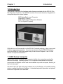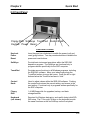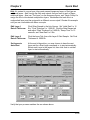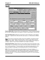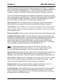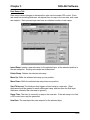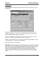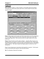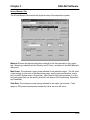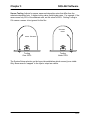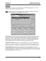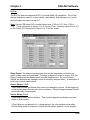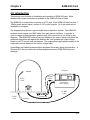
1
SID-242 Thin Film Deposition Controller SQS-242 Deposition Control Software SQM-242 Deposition Control Card Version 3.25 User’s Guide © Copyright Sigma Instruments, Inc. 1998-2005 Σ Sigma instruments Safety Information Read this manual before installing, operating, or servicing equipment. Do not install substitute parts, or perform any unauthorized modification of the product. Return the product to Sigma Instruments for service and repair to ensure that safety features are maintained. Safety Symbols WARNING: Calls attention to a procedure, practice, or condition that could possibly cause bodily injury or death. CAUTION: Calls attention to a procedure, practice, or condition that could possibly cause damage to equipment or permanent loss of data. Refer to all manual Warning or Caution information before using this product to avoid personal injury or equipment damage. Hazardous voltages may be present. Earth ground symbol. Chassis ground symbol. Equipotential ground symbol. Warranty Information Hardware Warranty: This Sigma Instruments product is warranted against defects in material and workmanship for a period of 2 years from the date of shipment, when used in accordance with the instructions in this manual. During the warranty period, Sigma will, at its option, either repair or replace products that prove to be defective. Software Warranty: Sigma Instruments warrants that the media on which this software is supplied will be free from defects for a period of 90 days from the date of shipment. Sigma Instruments does not warrant that 1) the software and any updates will be free from defects, 2) the software will satisfy all of your requirements, 3) the use of the software will be uninterrupted or error free. Limitation of Warranty Defects from, or repairs necessitated by, misuse or alteration of the product, or any cause other than defective materials or workmanship are not covered by this warranty. NO OTHER WARRANTIES ARE EXPRESSED OR IMPLIED, INCLUDING BUT NOT LIMITED TO THE IMPLIED WARRANTIES OF MERCHANTABILITY AND FITNESS FOR A PARTICULAR PURPOSE. UNDER NO CIRCUMSTANCES SHALL SIGMA INSTRUMENTS BE LIABLE FOR CONSEQUENTIAL OR OTHER DAMAGES RESULTING FROM A BREACH OF THIS LIMITED WARRANTY, OR OTHERWISE. Return Policy The purchaser may return this product in new condition within 30 days after shipment for any reason. In case of return, purchaser is liable and responsible for all freight charges in both directions. Sigma Instruments 120 Commerce Drive, Unit 1 Fort Collins, CO 80524 USA 970-416-9660 970-416-9330 (fax) Software License Agreement Sigma Instruments grants to you, the Licensee, a non-exclusive license to use this software on any computer, as long as only one copy is used at a time. Sigma Instruments retains ownership of the software. Licensee may transfer the software to another party, so long as the party agrees to accept the terms of this agreement. Licensee may terminate this license by destroying all copies of the software. Table of Contents Chapter 1 1.0 1.1 1.2 1.3 1.4 Chapter 2 2.0 2.1 2.2 2.3 2.4 2.5 2.6 2.7 2.8 Introduction SID-242 Introduction........................................................................................ 1-1 SRC Series Computer ..................................................................................... 1-1 SQM-242 Deposition Control Card .................................................................. 1-2 SQS-242 CoDeposition Control Software........................................................ 1-2 Digital I/O......................................................................................................... 1-3 Quick Start Introduction...................................................................................................... 2-1 Installation ....................................................................................................... 2-1 Front Panel...................................................................................................... 2-2 Program Startup .............................................................................................. 2-3 Single Layer Process Setup ............................................................................ 2-5 Single Layer Process Simulation ..................................................................... 2-9 SoftKey Functions ........................................................................................... 2-12 Multi-Layer CoDeposition Process .................................................................. 2-13 Conclusion....................................................................................................... 2-16 Chapter 3 SQS-242 Software 3.0 Introduction...................................................................................................... 3-1 3.1 Installation and Registration ............................................................................ 3-2 3.2 Operation......................................................................................................... 3-3 3.3 File Menu......................................................................................................... 3-5 3.3.1 Process Select............................................................................................ 3-5 3.3.2 Open/Save Database ................................................................................. 3-5 3.3.3 Data Logging .............................................................................................. 3-6 3.3.4 Printing ....................................................................................................... 3-7 3.3.5 User Login .................................................................................................. 3-7 3.3.6 Exit.............................................................................................................. 3-7 3.4 Edit Menu ........................................................................................................ 3-8 3.4.1 Processes................................................................................................... 3-8 Layers..................................................................................................... 3-10 Rate Ramps............................................................................................ 3-12 Deposition............................................................................................... 3-13 Conditioning............................................................................................ 3-15 Sources and Sensors ............................................................................. 3-16 Errors...................................................................................................... 3-18 Analog Inputs.......................................................................................... 3-20 3.4.2 Films ........................................................................................................... 3-21 3.4.3 Materials ..................................................................................................... 3-22 Chapter 3 SQS-242 Software (continued) 3.4.4 System........................................................................................................ 3-23 Outputs ................................................................................................... 3-24 Sensors .................................................................................................. 3-25 Analog .................................................................................................... 3-26 Indexers.................................................................................................. 3-27 I/O Events............................................................................................... 3-28 Card and Display Setup......................................................................... 3-32 Comm Setup........................................................................................... 3-33 3.4.5 Security....................................................................................................... 3-35 3.5 View Menu....................................................................................................... 3-37 3.6 Specifications .................................................................................................. 3-39 Chapter 4 4.0 4.1 4.2 4.3 4.4 Introduction...................................................................................................... 4-1 Installation ....................................................................................................... 4-2 Sensor Connections ........................................................................................ 4-2 Power Supply Connection ............................................................................... 4-2 TroubleShooting .............................................................................................. 4-3 Chapter 5 5.0 5.1 5.2 5.2 Digital I/O Introduction...................................................................................................... 5-1 PLC Installation ............................................................................................... 5-1 PLC Setup and Test ........................................................................................ 5-3 PLC Programming ........................................................................................... 5-4 Chapter 6 6.0 6.1 6.2 6.3 6.4 6.5 6.6 SQM-242 PC Card Computer Interface Introduction...................................................................................................... 6-1 Serial Interface ................................................................................................ 6-1 Ethernet Interface ............................................................................................ 6-1 ActiveX (COM) Interface.................................................................................. 6-1 SQS-242 Comm Program................................................................................ 6-2 Protocol ........................................................................................................... 6-3 Command Summary........................................................................................ 6-6 Appendix A. Material Parameters B. Loop Tuning Chapter 1 Introduction 1.0 Introduction This manual covers both the hardware and software associated with the SID-242 Thin Film Deposition Controller. The SID-242 consists of four main elements, integrated into a complete deposition control system: SRC Series Rack-mount Computer SQM-242 PC Card(s) SQS-242 Windows CoDeposition Software PLC for Digital I/O (option) While the focus of this manual is on the SID-242 Controller package, it also covers each of these components separately. If you have purchased only the SQS-242 Software and/or the SQM-242 Card, we suggest that you also review Chapters 1 and 2 of this manual for important information. 1.1 SRC Series Computer Sigma’s SRC Series computers are Celeron (or better) class computers running the Microsoft Windows operating system. SRC computers use standard off-the-shelf components and Sigma’s custom rack-mount chassis to provide a compact, flexible, yet low cost instrument. Included in the 5.25” high rack-mount chassis are an LCD Display, a TouchPad pointing device, a setting Knob, and six SoftKeys. A standard keyboard is provided; an optional rack-mount keyboard is also available. 1-1 Chapter 1 Introduction 1.2 SQM-242 Deposition Control Card Sigma’s SQM-242 is a PCI expansion card for use in computers running the Microsoft Windows operating system. Each card measures up to four quartz sensors via BNC inputs, and supplies the control signal for two evaporation sources via a ¼” stereo phone plug. Up to six SQM-242 cards can be installed in a computer. A single SAM-242 piggyback card with four analog inputs and two control outputs can also be installed. Consult the separate SQM-242 card User’s Guide for detailed information on installing SQM-242 and SAM-242 cards. 1.3 SQS-242 CoDeposition Control Software Included with the SID-242 is Sigma’s SQS-242 software, a Windows-based program that provides all of the functions required for an eight sensor, six output, CoDeposition controller. It is optimized for use with the Setting Knob and six SoftKeys of our SID-242 controller. However, it will run on any Win98 or later system with our SQM-242 and SAM-242 cards installed. 1-2 Chapter 1 Introduction The six SoftKeys provide easy access to the common operating functions. A single tabbed dialog box provides all of the settings required for a thin film process. Material parameters, sensor/source setup, pre/post conditioning, and error conditions are all visible on a single screen. Process settings, numeric data, and graphical displays are displayed during all phases of deposition. The SQS-242 software stores process parameters in a Microsoft Access compatible database. This provides virtually unlimited access to desktop tools for building and analyzing thin film processes. The SQS-242 software can be controlled from another computer using the RS-232 or Ethernet command protocol. 1.4 Digital I/O Digital I/O for the SID-242 is provided through an inexpensive, external, programmable logic controller (PLC). This allows the PLC, and the associated I/O wiring, to be placed in a convenient location in a wiring cabinet. A single, serial communications cable runs to the SID-242 computer. The PLC provides electrical isolation, fail-safe operation, and extensive I/O processing capabilities through its ladder logic programming. See Chapter 5 for more information on digital I/O capabilities. 1-3 Chapter 1 Introduction 1-4 Chapter 2 Quick Start 2.0 Introduction This section covers the minimum system connections and initial setup required to run the SID-242 Deposition Controller. Consult later chapters of this manual for more detailed setup and operational instructions. 2.1 Installation WARNING: Care should be exercised to route SID-242 cables as far as practical from other cables that carry high voltages or generate noise. This includes other line voltage cables, wires to heaters that are SCR-controlled, and cables to source power supplies that may conduct high transient currents during arc down conditions. Rack Installation The SID-242 occupies a 5.25” high (4U) rack space. Install the unit in a 19” rack with the supplied hardware. Power Connection WARNING: Verify that the 120/240 Voltage Selector Switch, next to the power switch, matches your mains supply voltage. WARNING: Verify that the power cable provided is connected to a properly grounded mains receptacle. Sensor Input Connections Connect the BNC cables and oscillators from your vacuum chamber feedthrough to the desired SQM-242 Card Input(s). Refer to Chapter 4 for detailed instructions on system hookup to the SQM-242 card(s). Source Output Connections Connect the dual phone plug from the SQM-242 output jack to your evaporation supply control input. Refer to Chapter 4 for detailed instructions on wiring the SQM-242 output phone plug. Digital I/O Connections Digital I/O is not required for initial operation of the SID-242. Perform initial setup and checkout of the SID-242 before connecting your digital I/O. Refer to Chapter 5 for detailed information on wiring the SID-242 for digital I/O. Keyboard Connection A keyboard is supplied for initial user setup of Windows. Attach the keyboard to the keyboard input jack on the rear of the SID-242. 2-1 Chapter 2 Quick Start 2.2 Front Panel Floppy Disk SoftKeys TouchPad Control Knob Keylock Power Reset Front Panel Controls KeyLock Power Reset Insert key and turn clockwise to enable the power (red) and reset (gray) buttons. Turn key counterclockwise to disable the power and reset buttons. SoftKeys Provide basic instrument operations within the SQS-242 deposition program. The SoftKeys are functional only in programs written specifically for the SRC computer. TouchPad Provides mouse functions in all Windows programs, including the SQS-242 software. Move your index finger along the TouchPad surface to move the cursor. Press the left or right buttons below the TouchPad surface to “click.” Control Knob Used to adjust values within the SQS-242 software. Pushing the control knob stores the current setting, and moves to the next setting. Functional only in programs written specifically for the SRC computer. Floppy Disk 1.44 MB floppy disk for upgrades, backup, and data storage/transfer. Keyboard (not shown) Required for Windows data entry, and useful during initial SID242 setup. The F1 through F6 keys on the keyboard provide the same functions as the six SoftKeys on the front panel. 2-2 Chapter 2 Quick Start 2.3 Program Startup This section will start the SID-242 and run the SQS-242 deposition control program. Power On the Computer Insert the and turn clockwise to enable the power and reset buttons. Push the power button to start the computer. Start the Program The SID-242 will boot Windows from the internal disk and start the SQS-242 deposition program. If the SQS-242 program does not start automatically, use the TouchPad to double-click the desktop icon. Note: If you are prompted to register the software, just click Cancel for now. The SID-242 ships with one pre-assigned user. The user name is Super, with no Password. User Login Screen The SID-242 displays a progress bar during program startup, then a User Login screen. Select a User Name from the drop down box, enter the Password, then click OK. See Chapter 3 for more information on users, passwords, access levels, and registration. Process Database The SID-242 normally starts with the last active process displayed. If that process is not found, a Database Open dialog is displayed. Use the TouchPad to select the SQS242 database. Main Display As you operate the SID-242, the six SoftKey labels along the left of the screen will change to display appropriate functions. Along the top of the display is a menu of less commonly used functions. This menu is available only when the SID-242 is stopped (i.e. not running a deposition process). Simulate Mode Simulate mode allows you to familiarize yourself with SID-242 operation, and test process recipes. Simulate Mode will be used for the remainder of this chapter. If the first SoftKey is labeled “START SIMULATE” then the Simulate mode is active. Otherwise, click the “Edit” menu selection along the top of the display, then click “System.” On the Card tab, click the Simulate button. Select the “Close” SoftKey to activate Simulate mode. 2-3 Chapter 2 Quick Start 2.4 Single-Layer Process Setup We will build a simple single-layer process as an introduction. Create a New Process Click the “Edit” menu selection along the top of the display, then click “Process.” The Process Edit dialog will display the setup data for the active process. To create a new process, click the “New” button at the top of the Process Edit dialog box. Type a new process name using your keyboard, or the touchpad and on-screen keyboard. Click “Enter” to save the new process name. 2-4 Chapter 2 Edit Layer Parameters Quick Start ]Click the “Layer” tab to display the layer parameters. A Film is basically a material, plus the settings that will control its deposition. Select “Gold Sample” in the Film dropdown box. We will be simulating a quartz sensor input that is controlling the deposition rate of Output 1. Select Output 1 in the Output dropdown and Sensor(s) in the Input dropdown. Click the SetPt setting, and then use the Control Knob or your keyboard to adjust the rate setpoint to 10 Å/s. Adjust the “Final Thickness” to 1.000 kÅ. Time and Thickness Endpoints won’t be used for this example. System Setup determines the physical inputs and outputs that are used and displayed on the screen. For now use the Default system setup. Manual Start causes this layer to wait for user input before beginning. An optional user prompt is possible. We won’t use any indexers for this example, so select None. A thin-film deposition process consists of one or more layers of material evaporated onto a substrate The diagram below illustrates a complete deposition cycle for a single layer. Refer to this diagram as we set the remaining parameters. 2-5 Chapter 2 Edit Rate Ramps Quick Start It may be desirable to vary the deposition rate during a layer. For example, to deposit slowly at first, then more quickly once the initial material is deposited. Click the “Rate Ramps” tab, then click “Insert Ramp.” Adjust the “Start Thickness” to 0.400 kÅ, “Ramp Time” to 5 seconds, and “New Rate” to 15 Å/s. Note: Settings on the Layer and Rate Ramp tabs must be set for each layer in a process. Settings on the remaining four tabs (Deposit, Condition, Source/Sensor, and Errors) correspond to the Film that was selected on the Layers tab. This allows a Film’s settings to be used in a number of layers, without the need to individually adjust each layer. Edit Deposition Select the “Deposit” tab. This tab establishes the gain (P Term), time constant (I Term), and dead time (D Term) for your process. Set these values to 55, .7, and 0 respectively. Be sure Shutter Delay Enabled is not selected. Select Continuous for Rate Sampling. 2-6 Chapter 2 Quick Start Edit Pre/Post Conditioning Before deposition begins, the source material is often brought to a ready state by slowly raising the evaporation source power. Select the “Condition” tab and set each parameter to the values shown below. Edit Source/Sensor Select the “Source/Sensor” tab. Select the proper material for this film, “Gold.” Set the maximum power and slew rate that should be used for the selected material. Sensor Tooling adjusts for differences in the substrate deposition and that measured by each sensor. Select 100% for now. 2-7 Chapter 2 Edit Errors Quick Start Select the “Errors” tab to control the actions taken when a sensor or deposition control error occurs. You can elect to ignore errors (unlikely), stop deposition for this layer, or continue deposition at a fixed power level. Select Stop Layer for this example. Until a process is well established, it is best to enable only the Crystal Fail error checking. Uncheck the remaining error conditions. Save Edits Select the “Close Form” SoftKey to save this one-layer process. If you are prompted “Do you want to change….,” answer Yes to make this the current process. Your new single-layer process is now the active process in the main window. Notice the process, layer, and time information above the graph. 2-8 Chapter 2 Quick Start 2.5 Single-Layer Process Simulation If you have followed this chapter, you are ready to simulate a deposition process. First, take a look at the information provided on the main screen. Process Name, Elapsed Time, Run Number Layer Number Elapsed Time Operating SoftKeys Phase Name Time Elapsed/Remain Percent Complete Film Measurements Film(s) Film Settings Setup Displays Click the “View” menu and assure that these options are selected: Film Settings, Film Readings, and Automatic. Note that the settings “ribbon” along the right side of the screen displays the pre-conditioning parameters you entered in the previous section. Start Process Verify that the top SoftKey label displays “START SIMULATE.” If “START PROCESS” is displayed, follow the instructions at the end of Section 2.3 to enable simulate mode. Press the “START SIMULATE” SoftKey to start the process. 2-9 Chapter 2 Quick Start The process will start with preconditioning (i.e. Ramp1, Soak1, Ramp2, Soak2) as shown below. Once preconditioning is complete, the process will enter the Deposit phase. You may want to select “ABORT SIMULATE,” then “START SIMULATE” several times to familiarize yourself with the on-screen displays during preconditioning. You may also want to use the settings ribbon to adjust parameters while the process is running. Preconditioning Phases Because we selected “Automatic” in the View menu, the graph displays Output Power during preconditioning, then switches to Rate during the deposition phase. 2-10 Chapter 2 Quick Start As shown below, the initial deposition rate was 10 Å/s until a thickness of .400 kÅ. Then the deposition rate was ramped up to 15 Å/s, and held until the desired final thickness of 1.000 kÅ was achieved. At this point, this single-layer process is finished. Deposition Phase with one Rate Ramp You should adjust the PID parameters on the setting ribbon, then Start/Stop the process several times to become familiar with their effect on control loop response. Note: In Simulate Mode, a deposition rate is not “measured” until the output power exceeds 50%. 2-11 Chapter 2 Quick Start 2.6 SoftKey Functions As you have seen, the SoftKey functions remain constant during deposition. Spend a few minutes to become familiar with each of these SoftKey functions. START PROCESS Starts the first layer of a process when START is pushed. If AUTO->MAN is shown on the third SoftKey (AUTO mode) the process starts PreConditioning. If MAN->AUTO is shown on the third SoftKey (MANUAL mode) the process immediately starts in the Deposition phase. ABORT PROCESS Aborts the process. The process can only restart at the first layer. START LAYER Starts a stopped layer, or a layer that has been designated “Manual Start” in the process database. Starts the layer based on the state of the AUTO->MAN SoftKey as described above. STOP LAYER Stops the current layer. Also changes the function of the first SoftKey to NEXT LAYER. NEXT LAYER Abandons the current layer and moves to the next layer in the process. If it is the last layer of a process, the same as pushing ABORT PROCESS. AUTO->MAN When AUTO->MAN is pushed, the source output is set to manual control. You may adjust the output using the settings ribbon. Because the PID loop is not running, you can manually set the output power to different levels and observe the associated deposition rate. MAN->AUTO Returns the output to PID loop control. If the process is running (ABORT PROCESS and STOP LAYER shown on the first two SoftKeys) deposition continues. If the process is stopped, sets the output to zero and awaits a start command. ZERO Resets the thickness reading to zero. NEXT FILM Sequences the setting ribbon through each Film in a codeposition layer. NEXT SETTING When the settings ribbon is shown, sequences the setting knob action through each of the displayed parameters. 2-12 Chapter 2 Quick Start 2.7 Multi-Layer CoDeposition Process Our final example builds on the previous sections. If you have modified the setup of your process, return to Section 2.4 and adjust the process to those values. When your single-layer process matches Section 2.4, complete these steps: Duplicate a Layer Open the Edit Process dialog. Click on Layer 1, click the “Layer” tab, then click “Copy Layer.” Now click “Paste Layer.” A duplicate Gold Sample film will be added as Layer 2. Click “Paste Layer” again to add a third Gold Sample layer. Select a CoDep Film Select Layer 3 in the layers list. Now select “Silver Sample” in the Films dropdown and Output 2 in the Output dropdown. The layers list will update to show the new Silver Sample film assigned to Layer 3. Add a CoDep Layer Select Layer 3 in the layers list, then click “Cut Layer.” Now select Layer 1. Click “Paste CoDep.” The Silver Sample film will be added below Gold Sample as a codeposition layer. (Your setup should match the picture below.) We now have two layers in our process. Layer 1 has Gold being deposited from source Output 1 and Silver is being codeposited on Output 2. Layer 2 is Gold alone. 2-13 Chapter 2 Quick Start Hint: It’s easiest to copy a layer, then paste several temporary layers of that type as additional layers. Next, assign the films and outputs that you want to each of these additional layers. Now use “Cut Layer” on the temporary layers, and “Paste CoDep” to assign the film to the desired codeposition layers. Remember that each film in a codeposited layer must be assigned to a different source output! Review this example until you are comfortable with these concepts. Edit Layer 1 Rate & Thickness Click Silver Sample in the list of layers. Set “Initial Rate” to 15 Å/s, “Final Thickness” to 1.500 kÅ. Click the Rate Ramps tab and adjust “Start Thickness” to 0.400 kÅ, “Ramp Time” to 15 seconds, and “New Rate” to 0 Å/s. Edit Layer 2 Rate & Thickness Click the Layer Tab, then click Layer 2 Gold Sample. Set Final Thickness to .5000 kÅ. Set Layers to Auto Start At the end of deposition, you may choose to have the next layer wait for a Start Layer command, or to start automatically. Select each Layer in the layers list, then click Auto to set that layer to start automatically. Verify that your process matches the one shown above. 2-14 Chapter 2 Quick Start Edit Silver Conditioning Select the “Condition” tab and the Silver Sample layer. Set each parameter to the values shown below. Save Edits Click “Close Form” or press the first SoftKey to save this twolayer codeposition process. Answer Yes if it displays the “Do you want to change….” message box to make this the current process. Press the “START SIMULATE” SoftKey to start the first layer preconditioning phases. Note that two outputs are displayed for this codeposition layer. Start Process Preconditioning of the two materials is entirely independent. If the preconditioning of one layer takes longer than the other, the start times are adjusted so that the end times coincide. When preconditioning ends, codeposition of the two materials begins. 2-15 Chapter 2 Quick Start Your response should be similar to the graph shown below (your vertical scale may be slightly different). The slight ringing on the waveforms indicates some further tuning may be desired. However, this is an example of a reasonably well tuned loop. At .400kÅ thickness, the Silver Sample deposition rate ramps down from 15Å/s to 0. Similarly, at .400 kÅ thickness the Gold Sample film ramps to a higher deposition rate of 15Å/s. Because the initial rate for Gold was set lower than the initial rate for Silver, Gold reached its .400 kÅ thickness rate ramp trigger later in the deposition cycle. Try a P Term in the 25-30 range (less gain) for both Gold and Silver to decrease the loop susceptibility to noise. Increasing the I Term a little, say toward 1.0, will lessen overshoot during rate changes. The D term can be thought of as a “dead band” term. Most systems require little or no D term. 2.8 Conclusion Once again, spend some time with this process to become familiar with its setup, and the effect of changes on deposition performance. Because we selected Simulate Mode at the beginning of this Quick Start session, the SQM-242 card is “faking” an actual process. You can use the Simulate feature at any time to become familiar with SID-242 operation, and the effect of various settings on process performance. It is also a very useful feature for pre-testing your process setups. Return to the Edit menu, then select System and set the Mode to Normal to begin running your process with the SID-242 controller. 2-16 Chapter 2 Quick Start 2-17 Chapter 3 SQS-242 Software 3.0 Introduction The SQS-242 Deposition Control Software works with Sigma Instrument’s SQM-242 Card to provide a powerful, PC based Thin Film Deposition Controller that can: • • • • • • Measure up to eight quartz crystal sensors simultaneously Control up to six deposition source supplies simultaneously (CoDeposition) Provide PreConditioning, multiple rate ramps, and feed/idle phases Graph deposition rate, rate deviation, or power output Store process, film and material parameters in Microsoft Access® database Provide flexible and reliable digital I/O using an inexpensive PLC A typical deposition cycle for a thin film is shown below. The cycle can be broken into three distinct phases: pre-conditioning (ramp/soak), deposition, and post-conditioning (feed/idle). During pre-conditioning, power is applied to prepare the source material for deposition. The first ramp/soak preconditioning phase is used to bring the material to a uniform molten state. The second ramp/soak phase is typically set to a power that is near the desired deposition rate. When pre-conditioning ends, PID rate control of deposition begins. Initially, the substrate material may remain shuttered until the desired deposition rate is achieved (shutter delay). Once the control loop achieves the desired rate, the shutter opens and deposition begins. Multiple deposition rates (rate ramps) can be programmed. When the desired thickness is reached, the evaporation source is set to feed or idle power. At this point the process may be complete, or deposition of another film layer may begin. Up to six separate films can be codeposited within a single layer. There is no practical limit to the total number of processes, layers, or materials that can be stored in the process database. 3-1 Chapter 3 SQS-242 Software 3.1 Installation and Registration The SQM-242 card can be installed before or after the SQS-242 software. Consult the separate SQM-242 card User’s Guide for installation information. Note: CD-ROM installation on the SID-242 rack mount computer can be accomplished with an external USB CDROM, or by copying the CD-ROM “Disk” folder to 3 ½" diskettes. It is also possible to use the SID-242 Ethernet connection to install the software over a network. To install the program, insert the disk or CD-ROM. Click Start, then Run, then type <d>:Setup (where <d> is the drive you are using). Click OK to begin installation, and follow the on-screen prompts. When installation is complete, you may be prompted to restart the computer. To start the SQS-242 program, click Start, Programs, Sigma Instruments, then SQS242. Until the software is registered, this Registration "nag" screen will appear. Note: You may select Cancel for a maximum of 30 unregistered runs. After 30 runs you must contact Sigma Instruments to start the program. There is no work-around! Press OK to show the unlock screen. Unlock codes are in the SQS-242 CDROM sleeve. If a valid User ID and Unlock Code are entered, the program will start normally. Otherwise, after three tries the program will start in unregistered mode. Note: If you enter a name of DEMO and Unlock Code of 5A8CAC8E5586268 the software will be placed in Demo mode. All features of the software are permanently available, except that readings from the SQM-242 card are only simulated. The Demo mode can be disabled later by entering a valid User ID and Unlock Code. 3-2 Chapter 3 SQS-242 Software 3.2 Operation The SID-242 displays a progress bar during startup, then a User Login screen. Note: The SQS-242 software ships with one pre-assigned user. The user name is Super, with no Password. Do not confuse this with the registration Name and Unlock Code discussed in the previous section. Select a User Name from the drop down box, type in the Password, then click OK to start the program. If your software is configured for keyboardless operation, an on-screen keyboard will appear as shown below. You can use your normal keyboard or mouse/TouchPad to “type” the password, then click Enter. See System Setup, SQM-242 Setup later in this chapter to enable or disable the on-screen keyboard. An Access Level is associated with each User Name. The Access Level controls which software functions are available to each user. For example, only users with an Access Level of Supervisor can add new users. See the Security section of this chapter for information on setting up users. 3-3 Chapter 3 SQS-242 Software The remainder of this chapter covers the purpose and operation of each software function, arranged by menu selections. For a more “operational” approach, consult the previous Quick Start chapter. Menus: The menus along the top of the main screen provide access to functions for building deposition processes, configuring the hardware for your vacuum system, and data display. SoftKeys: The six switches to the left of the display are used for the normal operation of the instrument, and to navigate the setup programs (see below for the individual switch functions). Normally, you press the button that is adjacent to the labels on the SID-242 screen, but you can also use the mouse. Just move the cursor over the key label on screen and single click the mouse. You can also use the keyboard F1 to F6 function keys to simulate the front panel function switches. The SoftKeys change during operation to address different user input requirements. Setting Knob: The knob to the right of the display is used by the SID-242 to set numeric data. The keyboard +/- keys, or the on-screen up/down arrows can also be used. TouchPad: On the SID-242, a TouchPad is located below the setting knob. The TouchPad serves the same function as a normal mouse. Use the TouchPad or mouse to access the menus, and for functions not available from the six function keys. 3-4 Chapter 3 SQS-242 Software 3.3 File Menu Note: The current process must be stopped for the File menu to be available. 3.3.1 File: Process Used to select a process from a list of all processes in the current database. If the process selected is different than the current process, you are prompted to confirm the change. 3.3.2 File: Open and Save Database Open Database: Selects a process database to be used for deposition. Remember, a single process database may contain an unlimited number of processes, films, and materials. Note: A read-only demo database (VER_DEMO.MDB) is included with each release. To use this database, use Windows Explorer to make a copy, then right click the new file and uncheck the read only property. Save Database As: Saves the current process database to disk under a different name. This is useful for saving the process database to floppy disk (for backup!), or for making trial changes without affecting your working database. Process databases are saved in Microsoft Access format. Once again, a pop-up keyboard may appear. If you want to browse, just select Cancel from the pop-up keyboard. 3-5 Chapter 3 SQS-242 Software 3.3.3 File: Data Logging Logs data from a deposition process to a disk .LOG file. There are four options for file naming and logging. Log File: Select "None" to disable data logging. If “Overwrite” is selected, the last run of the process is saved as FileName.LOG (where FileName is the name shown in the FileName text box). Subsequent runs overwrite the log file. If “Append” is selected, each run is appended to FileName.LOG. If “Run#” is selected, each run of the process is saved as a separate file under the format FileName_Run#.LOG. Changing Run# on this screen will also change the Run# displayed at the top of the main program screen. Normally, the log file is saved to the folder where the program is installed. If desired, you can click Select and navigate to a different folder. Log files can be viewed in Notepad by clicking the View button. Note: To avoid delays in data acquisition DO NOT log data to a floppy disk file. Instead, save to the hard disk, and transfer the files to a floppy disk later. Events to Log: A number of “events” can trigger a data entry in the log file. “End Deposit Phase” records process data (rate, thickness, time, etc.) at the end of each layer’s deposit phase. Similarly, “End Each Phase” logs data at the end of each phase (conditioning, depositing, etc.). “I/O Events” logs data each time an external digital input or output changes. “Timed” logging records data at the selected time intervals throughout the process. 3-6 Chapter 3 SQS-242 Software Click the Sensors box to include individual sensor data in addition to the normal film based data. Click Analog Inputs to also log that data. Finally, click “Readings” to log every reading from the SQM-242 card(s). The file will be saved in the application directory with a name in yymmdd.log format. That is, readings logged on January 15, 2004 will be saved as 040115.log. Note: This file can grow quite large and cause Windows to slow significantly. Typically, the “Timed” option is a better choice unless you must record every reading. When “Readings” is selected, a reminder screen appears each time the SQS-242 program is started. Format: There are two formats for writing data. If “Spreadsheet” is selected, each entry is a comma-delimited line of data. If “Text” is selected, the data is formatted for easy reading. The first few lines of the LOG file is a heading that illustrates the file format and content. Note: If you wish to use a different delimiter than a comma, change the SQS242.INI file so that under the [DataLog] section, the LogDelimit= entry shows the character you wish to use. To use a <TAB> character, type the word Tab. 3.3.4 File: Print Print Process: Prints the parameters for the current process to the system printer. Select “Print to File” in the Printer Setup Menu to print the data to a file. Print Setup: Selects and modifies the current system printer. 3.3.5 File: User Login Displays the User Login screen so that a different user may log in. The existing user is logged off automatically. The user Access Level changes immediately to that of the new user. See the Edit, Security section for more information on Users, Passwords, and Access levels. 3.3.6 File: Exit Exits the SQS-242 deposition control program and saves the current data. 3-7 Chapter 3 SQS-242 Software 3.4 Edit Menu 3.4.1 Edit: Process A process is a sequence of thin film layers. Multiple films deposited in the same layer are known as CoDeposition. The Edit Process dialog provides the functions needed to develop a thin film deposition process from the database of existing films and materials. Controls along the top of the Process Edit dialog box apply to the entire process: Process: A dropdown box that selects the process to be edited. Defaults to the current process. Below the process dropdown, a listing of each layer assigned to the Process. CoDeposition layers are listed with the same layer number, but a different output. Rename: Edits the name of the selected process. New: Creates a new process. Since every process must have at least one film, the first film of the currently selected process is used. Delete: Deletes the selected process from the database. There is no undelete! Copy: Creates a duplicate of the currently selected process. Layers List: To select a process layer, click on it in the Layers list. 3-8 Chapter 3 SQS-242 Software Cut/Copy/Paste the selected layer as described below: Cut Layer: Removes the selected layer from the process and places the layer on the clipboard. Copy Layer: Places the layer selected in the Layers list box on the clipboard, without removing it from the process. Paste Layer: Inserts the clipboard layer above the currently selected layer in the Layers list box. Existing layers are shifted down. Paste CoDep: Pastes the clipboard layer as a CoDeposition layer at the currently selected layer number. Attempting to paste a layer that uses an output already assigned to the selected layer generates an error message. Hint: To add layers to a process, it is easiest to select an existing layer in the layers list, then click Copy. Click Paste repeatedly to insert several temporary layers. Next, assign the proper film and layers parameters to each of these temporary layers. To change one of the temporary layers to a CoDep layer, highlight the temporary layer and click “Cut Layer.” Next click the layer desired for CoDep and click “Paste CoDep” to assign the selected layer. The Multi-Layer CoDeposition Process section of Chapter 2 illustrates this concept. Controls in the tabbed control apply to the layer selected above, in the Layers list. The Layer and Rate Ramp tabs assign layer-specific parameters to the selected layer. Note that captions on the Layer tab may change, depending on the input and output selections. The remaining tabs provide access to the film assigned to the selected layer. Note: Edits to the Deposition, Condition, Source/Sensor, and Error tabs will affect all processes and layers that use the selected film! 3-9 Chapter 3 SQS-242 Software Layer Tab Film DropDown Box: Assigns a film to the selected layer. A film is basically a Material, plus the other settings shown on the Deposit, Condition, Source/Sensor, and Error tabs. Output DropDown Box: Selects the output that is used for deposition of the selected layer’s film. A particular film often uses the same output (i.e. a thermal boat or EBeam pocket). Note: Due to the way outputs are stored in the process database, the physical output number (not its name) is listed in the layers listing. Outputs 1 and 2 refer to the first SQM-242 card outputs. Outputs 3 and 4 refer to the second SQM-242 card outputs (if installed). Outputs 13 and 14 are the SAM 242 card outputs (if installed). Input DropDown Box: Selects the input used to measure and control deposition of the selected layer. The combination of an output and its input defines the deposition “control loop” for the selected layer. The Input selection can significantly alter operation of the deposition phase, as described in the following discussion on the SetPt parameter. SetPt: The function of the setpoint parameter depends on the Input dropdown. If Sensor(s) are used as the input, the setpoint is Rate (in A/s). This sets the initial Rate setpoint for the selected layer. Rate is controlled by the PID parameters for the film assigned to the layer. If no rate ramps are defined for the layer, this is the rate setpoint for the entire layer. 3-10 Chapter 3 SQS-242 Software If the Input selected is Timed Power, the setpoint is shown as % Power. This sets a fixed % output Power during deposition. In Timed Power the Time Endpoint establishes the length of time for the deposition cycle. The layer will end when either the time endpoint is reached, or when the Final Thickness is reached, whichever occurs first. If one of the SAM-242 analog inputs are selected, the setpoint is in volts (or the analog input’s corresponding user-defined units). The layer will end when either Time Endpoint or Final Thickness is reached, whichever occurs first. See the Analog Inputs section later in this chapter for a discussion of programming for analog inputs. Final Thickness: Sets the endpoint thickness for the layer. When final thickness is reached, deposition is stopped for that layer and the feed/hold phase is entered. Time EndPoint: Sets an arbitrary time, after deposition begins, when the time setpoint relay is activated. During % Power and Analog Input deposition, it also sets the length of the deposition cycle. Thickness EndPoint: Sets an arbitrary thickness that activates the thickness limit relay. Auto/Manual/Continuous Start: Auto Start begins the next layer automatically upon completion of the previous layer. Continuous ignores Conditioning phases and controls continuously at rate setpoint (see Analog Inputs). If Manual Start is selected, the previous layer ends at its idle power and waits for the user to push the Start Layer switch. An optional User prompt can be entered for Manual Start layers. (This feature can be disabled by editing ShowPrompts in the SQS242.INI file). Note: The following parameters are common to all of the films in a layer. In the previous screen shot for this section, both layer 1.1 and 1.2 would share common values for the following parameters. Layer 2.1 could have different values. System Setup: System setup assigns outputs to their controlling sensors (called sensor mapping). It also determines which physical sensor and output connections are displayed on the main screen. See Edit, System for detailed System Setup information. Source Index: Assigns each film to a specific source indexer pocket (one of 16 values). Each of the six possible outputs is associated with a unique source indexer. These values are sent to the digital I/O (PLC) at the beginning of each layer. Substrate Index: If using a substrate indexer, assigns the substrate to one of 16 possible values. These values are set at the beginning of each layer. User1/User2 Index: These additional values are output to the PLC for use as needed. Common applications are to select external equipment configurations. (The Index names, the range of values (0 to 15, or 1 to 16), and the first entry can be customized by editing entries in the SQS242.INI file). 3-11 Chapter 3 SQS-242 Software Rate Ramps Tab Rate ramps cause changes to the deposition rate over time under PID control. Each rate ramp has a starting thickness, an elapsed time to ramp to the new rate, and a new rate setpoint. Each process layer can have an unlimited number of rate ramps. Insert Ramp: Inserts a new rate ramp for the selected layer, at the selected position in the rate ramps list. Existing rate ramps are shifted down. Delete Ramp: Deletes the selected rate ramp. Move Up: Shifts the selected rate ramp up one position. Move Down: Shifts the selected rate ramp down one position. Start Thickness: The thickness that triggers a timed ramp to a new rate. (Start thickness should be greater for each subsequent ramp, and less than the final layer thickness, otherwise the rate ramp is ignored.) Ramp Time: The time (in seconds) to ramp to the new rate. If the rate ramp is too fast, a PID control error may be generated. New Rate: The new deposition rate setpoint for the selected layer. 3-12 Chapter 3 SQS-242 Software Deposition Tab The deposition tab contains parameters that directly affect the deposition phase of the process cycle. P Term: Sets the gain of the control loop. High gains yield more responsive, but potentially unstable loops. Try a value of 25, then gradually increase/decrease the value to respond to step changes in rate setpoint. I Term: The integral term controls the time constant of the loop response. A small I term, say 1 to 3 seconds, will smooth the response of most loops. D Term: The differential term causes the loop to respond quickly to changes. Use 0 or a very small value (.1 x I Term) to avoid oscillations. See the Appendix B for loop tuning tips. Shutter Delay: It is often desirable to assure stable process control before the substrate shutter opens. Enabling shutter delay requires that the system reach the programmed shutter delay Accuracy, and maintain that accuracy before deposition begins. If the accuracy is not reached within Wait seconds, the process halts. If accuracy is achieved, and maintained for Hold seconds, then the substrate shutter opens and deposition begins. The Thickness reading is zeroed at the end of the shutter delay period. 3-13 Chapter 3 SQS-242 Software Rate Sampling: Rate sampling can extend the life of crystals. With rate sampling, the deposition rate is sampled for a period of time, then the sensor shutter is closed. Power is then held at the same level as the final power setting during the sample period. Continuous selects no sampling; the sensor shutter remains open during deposition. Accuracy Based sampling opens the shutter until the desired accuracy is reached, leaves the shutter open for Sample time, then closes the shutter and holds power constant for Hold time. Time Based sampling opens the shutter for a fixed period of time then closes it for a fixed time. 3-14 Chapter 3 SQS-242 Software Condition Tab Before deposition begins, it is often necessary to PreCondition the source material. This places the system at the proper power level to achieve rapid PID control when deposition begins. Ramp 1: Ramp power sets the power level that is desired at the end of the ramp phase, in % of full scale. Ramp time sets the time to ramp with a linear rate from the initial power to the Ramp power. Soak time sets the time the output remains at the ramp power level. Ramp 2: Ramp 2 functions are the same as Ramp 1. Typically, Ramp 2 power is set near the power level required to match the desired initial deposition rate. Selecting the Ramp2 Power Auto checkbox stores the power over the last few seconds of the deposit phase for this film. That value is used as the Ramp2 power for the next run of the selected film. Feed: The feed phase begins immediately after deposition is complete. It holds output power at the level and time required to wire feed new material. Idle: The Idle phase follows the Feed phase. 3-15 Chapter 3 SQS-242 Software Source/Sensor Tab The Source/Sensor tab controls the physical setup of the deposition system. Material: Selects the physical deposition material for the film selected on the Layers tab. Selecting a material sets the Density and Z Factor, as defined in the Edit Materials dialog box. Max Power: The maximum output power allowed for the selected output. The full scale output voltage is a function of the deposition power supply input specifications, and is set in the Edit System menu, Outputs tab. Max Power controls the maximum % of the full scale power that can be used by this film in all phases (PreConditioning, Deposition, and Feed/Idle). Slew Rate: The maximum power change allowed on an output, per second. If rate ramps or PID power requirements exceed this value, an error will occur. 3-16 Chapter 3 SQS-242 Software Sensor Tooling: Adjusts for sensor measured deposition rates that differ from the substrate deposition rate. A higher tooling value yields higher rates. For example, if the sensor sees only 50% of the substrate rate, set the value to 200%. Setting Tooling to 0% causes a sensor to be ignored for this film. Substrate Substrate Tooling Over 100% Tooling Under 100% The System Setup selection on the Layer tab establishes which sensor(s) are visible. Only those sensors “mapped” to the layer’s output are visible. 3-17 Chapter 3 SQS-242 Software Errors Tab Several source or sensor error conditions are possible during deposition. This tab establishes the program's response to errors. Note: It is best to leave all error settings, except Crystal Fail, disabled until you are confident of the stability and repeatability of your process. Control Error: If the control loop cannot maintain the desired deposition rate (due to loss of source material, excessively high rate ramps, or equipment malfunction) a control error occurs. Control error % is the accuracy that must be exceeded for the specified time (in seconds) to trigger a control error. Use shutter delay accuracy to assure adequate process control before entering the deposition phase. Crystal Fail: Establishes the number of bad readings (i.e. 0 Hz) from a sensor that generates a Crystal Fail condition. If a crystal fails, the PID loop will send the source supply to max power. Therefore, it is unlikely you will ever want to disable this error. Crystal Quality: Each time the rate deviation for this film exceeds the % value, a counter is incremented. Each time the rate deviation is within the % value, the counter is decremented (to zero minimum). If the counter exceeds the Counts value during the entire layer deposition, an error occurs. 3-18 Chapter 3 SQS-242 Software Crystal Stability: When material is being deposited, a crystal's frequency normally drops. At the end of crystal life, sensor frequency may briefly "mode hop" to higher frequencies. Single Hz is the largest single positive frequency shift allowed. Total Hz is the sum of positive shifts allowed during a film's deposition. On Error: When an error condition occurs, three actions are possible. Ignore the error and let the PID loop attempt to maintain rate control. Stop the layer and allow the user to fix or manually control deposition. The last choice, Timed Power, uses the last good Rate/Power settings to "estimate" rate and thickness. In Timed Power, the output is set to the power level that last yielded a rate reading within the Control Error % deviation setting (10% deviation if Control Error is disabled). The program then calculates the estimated thickness based on that rate and the deposition elapsed time. When the calculated thickness reaches thickness setpoint, deposition stops. 3-19 Chapter 3 SQS-242 Software Analog Inputs Normally the SQS-242 software uses SQM-242 card quartz sensor inputs to measure or control rate and thickness. The SAM-242 Analog Input Card extends this capability to allow measurement and control on DC voltage-based process variables such as temperature transmitters, pressure/flow controllers. Analog input based control is treated, for the most part, identically to quartz sensor based control. Considerations for using an analog input are discussed below. Layers Tab: In the Inputs dropdown, select one of the Analog inputs. In the Outputs dropdown, select the output that is to be controlled. Enter the desired setpoint. Normally this setpoint is in Volts, but can be converted to other units (e.g. degrees or PSI) in the Edit, System, Analog screen. Use Time Endpoint to stop the analog layer after a set time. Otherwise, a Sensor input, programmed as a Codep layer, can control the layer endpoint. Final Thickness and Thickness Endpoint settings have no effect for an analog input. If Continuous Start is selected the analog input controls to its programmed Layer Setpoint through all of the Ramp/Soak/Feed phases. This allows temperature or pressure control (for example) to be maintained through all phases of the layer. If Stop Layer is selected, control is still maintained at setpoint. Pressing Abort Process will set the output to zero. Rate Ramps Tab: Setpoint ramps can also be programmed for an analog signal. Deposition Tab: The PID and Shutter Delay controls operate the same as a Sensor input. Rate sampling is not possible for analog inputs. Condition Tab: Conditioning is identical to that of a Sensor input with one significant exception. Source/Sensor Tab: Only Max Power and Slew Rate are functional. Errors: Only Control Error applies. The Analog Input’s measured value (converted to the defined units) and deviation from setpoint are shown below the graph. The analog input values are NOT shown on the normal Rate graph (the values could lead to poor rate resolution on the graph). Instead the analog input voltages are shown on the View, Analog graph. Volts are displayed on this graph, rather than the scaled units (again, to maintain adequate graph resolution). 3-20 Chapter 3 SQS-242 Software 3.4.2 Edit: Films The Edit Films dialog box allows you to rename, delete, and copy films. The functions in the tabbed control are identical to those for this film on the Edit Processes dialog. Note: Edits to a Film will affect all processes and layers that use that film! Film: A dropdown box that selects the film parameters displayed in the edit film dialog box. Rename: Edits the name of the selected film. New: Creates a new film. Delete: Deletes the currently selected film from the database. A film cannot be deleted if it is used in ANY process! To delete a film, you must first delete the film from each process where it is used. Copy: Creates a duplicate of the currently selected film. The function of each Edit Films tab, and its associated controls, are identical to those detailed in the Edit Processes section. Please consult Section 3.4.1 for that information. 3-21 Chapter 3 SQS-242 Software 3.4.3 Edit: Materials The Edit Material dialog box provides the functions needed to build a materials database. In addition to the functions listed below, the main screen SoftKeys provide capabilities to add/edit/delete materials. Note: See the Appendix for a list of standard Material Density and Z-Factor. Rename: Edits the name of the selected material. New: Creates a new material. Delete: Deletes the currently selected material from the database. A material cannot be deleted if it is used in ANY process! To delete a material, you must first delete each film where it is used. Material: Selects a material to edit. Density: Sets the density for this material. Material density has a significant impact on deposition calculations. Z-Factor: Sets the Z-factor, a measure of a material’s effect on quartz crystal frequency change. Z factor has no effect on measurements when using a new crystal. If the Z Factor for your material is not known, using crystals with >80% life will eliminate the effect of the Z Factor term. 3-22 Chapter 3 SQS-242 Software 3.4.4 Edit: System The System Setup dialog box configures the SQS-242 software to the physical setup of your deposition system. Several settings that control the overall operation of the program are also accessed in System Setup. The combination of sensor input and control output assignments, known as a System Setup, are stored in the SQS-242 database. Most systems will have a single setup that applies to all processes. However, complex systems may use several different system setups within a single process. Note: Settings on the Outputs, Sensors, Analog, and Cards tabs are unique for each System Setup. Settings on the Indexers, I/O, and Comm tabs apply to all System Setups. Output colors are also common to all setups. Controls along the top of the System Setup dialog box apply to the selected system setup: System Setup: A dropdown box that selects the setup to be edited. Defaults to the current setup. Rename: Edits the name of the selected setup. New: Creates a new system setup, based on the existing default setup. Delete: Deletes the currently selected setup from the database. If the setup is used in a process, an error message is displayed. Copy: Creates a duplicate of the currently selected system setup. 3-23 Chapter 3 SQS-242 Software Outputs Tab Name: Assigns a name to each displayed output. For clear display, keep the name to less than 8 characters. Physical Output: Up to six SQM-242 cards (physical outputs 1 to 12) and a single SAM-242 card (physical outputs 13 and 14) may be installed in a computer. However, the SQS-242 software can display and control a maximum of 6 outputs simultaneously. Use this dropdown to assign a “physical” output to a “display” output. FS Out: The input voltage required by the deposition source power supply to produce 100% output power. Positive or negative full scale values are possible. Color: Selects the color used to graph and display output data. Test Output: Useful for testing output wiring and Full Scale voltage settings. Select an output, then click Full Scale to set the SQM-242 card output to its Full Scale voltage. Click Zero to return the selected output to 0 volts. 3-24 Chapter 3 SQS-242 Software Sensors Tab Name: A meaningful name assigned to each sensor. For clear display, keep the name to less than 8 characters. Physical Sensor: Up to six SQM-242 cards (physical sensors 1 to 24) may be installed in a computer. However, the SQS-242 software can display a maximum of 8 sensors simultaneously. Use this dropdown to assign a “physical” sensor to a “display” sensor. Dual: Indicates that a pair of sensors is set up as primary/secondary duals. When a primary sensor fails, the SQS-242 switches to the secondary sensor. Monitor Output: Select the output that each sensor is positioned to measure. The rate and thickness displayed by the sensor will be calculated based on the material assigned to the selected output. Control Checkboxes: Click Rate to assign the sensor to the PID rate control loop for the assigned output during deposition. Click Thk to use the sensor for Thickness endpoint detection. Typically you will check both boxes so that the sensor controls to rate setpoint and detects the thickness endpoint. If multiple sensors are assigned to control the same output, the sensor readings are averaged when calculating rate and thickness. Uncheck both boxes to have a sensor monitor an output, without controlling deposition rate or stopping when final thickness is reached. 3-25 Chapter 3 SQS-242 Software Analog Tab The SAM-242 analog input card measures DC voltages in the +/-10 volt range. These voltages may represent temperature, flow, or any other process variable. The analog tab allows you to modify the display to show values in the desired units, using a linear (y = mx + b) transformation. For example, assume you have a temperature transmitter that sends 0V at 0°C and 1V at 100°C. To display temperature in °F, set the Gain to 180, Offset to 32, and Units to DegF. The SQM-242 will display setpoints and measurements associated with the analog input in degrees F. To leave the analog input display in Volts, set Gain = 1 and Offset = 0. Name: A meaningful name assigned to each analog input. For clear display, keep the name to less than 8 characters. Gain: The gain term for transforming voltage to measured units. This is the m term in y = mx + b. Offset: The offset term for transforming voltage to measured units. This is the b term in y = mx + b. Units: The units that you wish to display for the analog input. 3-26 Chapter 3 SQS-242 Software Indexers Tab Source Indexers: A unique source indexer (pocket rotator) is available for each output used. The source indexer moves at the beginning of each layer. Layer Indexers: Three “layer indexers” are also available. Layer indexers also move at the beginning of each layer. Layer indexer values are useful for control of substrate indexers or other external process equipment. Note: The Layer Indexer names, the range of values, and the first entry can be customized by editing entries in the SQS242.INI file. Complete Signal: Check this box if your indexer sends a signal indicating that the move is complete. Timeout: If Complete Signal is checked, the process will halt if a move complete signal is not received within this timeout period. If Complete Signal is not checked, the process waits for this fixed time period before starting a layer. Move: Useful for testing indexer functions manually. Select an indexer, then an index (pocket). Click Move to move to the selected index. Layer indexers are typically named Substrate, User 1, and User 2. Layer indexer names can be edited in the SQS242.INI file. 3-27 Chapter 3 SQS-242 Software I/O Tab The SID-242 uses an inexpensive PLC to provide digital I/O capabilities. The I/O tab assigns deposition events (i.e. open shutter, start deposit, final thickness, etc.) to the physical relays and inputs on the PLC. Note: Omron CPM series PLCs number relays from 10.00 to 10.07, then 11.00 to 11.07. These correspond to Relays 1 to 16 on the I/O tab. Similarly, inputs 0.00 to 0.11 on the Omron PLC correspond to inputs 1 to 12 on this screen. Relay Events: The relay events dropdown box lists the deposition events that can cause a relay output to be activated. To assign a deposition event to a relay, click the Relay #, then select the desired event from the dropdown box. As you click each Relay#, the dropdown will change to show its currently assigned event. A description of each relay (output) event follows: Source Shutter 1 to 6 These relays control the Shutter that covers your deposition source. At the beginning of the deposit phase the relay will close its contacts. When the deposit phase finishes the shutter relay contacts open. Sensor Relays 1 to 8 These relays control sensor shutters. Their function depends on whether you have single or dual sensors. If Dual Sensor is not selected (i.e. a single sensor), the relay contacts close when Shutter Delay phase is entered on a layer with the sensor enabled. As an example, 3-28 Chapter 3 SQS-242 Software let’s say you have sensors 1 and 3 enabled for Film 1 and sensors 2 and 4 enabled for Film 2. When you start Film 1 Shutter Delay phase, the contacts for Sensor Relays 1 and 3 will close. When you start Film 2, these contacts open and the contacts for Sensor Relays 2 and 4 will close when Shutter Delay is entered. If the software is configured for dual sensors, the relay operation is considerably different. Dual sensors use pairs of sensors, i.e. Sensor 1 and 2, or Sensor 3 and 4. With Sensors 1 or 3 selected, the associated relay contacts are open. If a Crystal Fail is detected, the relay contacts for the failed sensor will close to select the second sensor in the Dual Sensor assembly for the duration of the film. Xtal All Good and Xtal All Fail Relays These two relays provide an indication of the general health of your sensors. If the Xtal All Good Relay is closed, then all enabled sensors are returning a valid reading. If the Xtal All Fail Relay is closed, none of the enabled sensors are returning a valid reading. Process Stopped and Running Relays These relays indicate the overall status of the process. The Process Running relay closes as soon as Start Process is selected (by front panel or digital input), and opens when Abort Process is selected. Even if a layer is stopped within a process, the Process Running relay remains closed until the last film of a process has finished. The Process Stopped relay contacts behave in the inverse manner. Layer Stopped and Running Relays The Layer Running relay closes as soon as Start Layer is selected (by front panel or digital input), and opens when Stop Process is selected. The Layer Stopped relay contacts behave in the inverse manner. Deposit Phase Relay This relay indicates that you are in the deposit phase of a film. It is like having the two Source Shutter Relays connected in parallel. If you have shutter delay enabled, this relay will wait until the end of the shutter delay before going active. Pre-Cond Phase Relay This relay closes for the preconditioning phases (Ramp1, Soak1, Ramp2, Soak2) of a film. Soak Hold Phase Relay This relay closes for the Soak and Hold phases after deposition. Process Active Relay This relay action is similar to the Process Running relay, except it will open if the process is temporarily halted for any reason, e.g. a Manual Start layer. Manual Mode Relay Closes when the program is placed in Manual mode. 3-29 Chapter 3 SQS-242 Software Max Power Relay Closes when any control voltage output is at the programmed maximum power level. Thickness Setpoint Relay This relay will become active when the Thickness Setpoint is reached. This is a programmable process parameter. Time Setpoint Relay This relay will become active when the Time Setpoint has been reached. This is measured from the beginning of the deposit phase, and is a programmable parameter. Test: The Test section provides a simple means of testing I/O wiring. To close a relay, select the desired relay button, then click Set. Click Clear to open the relay contacts. Input Events: The input events dropdown box lists the deposition events that can be caused by an external digital input. To assign a deposition event to an input, click the Input #, then select the desired event from the dropdown box. As you click each Input #, the dropdown will change to show its currently assigned event. A brief description of each input event follows: Start Process Input Triggering this input is the same as pushing the Start Process button. Abort Process Input Triggering this input will abort the process. Start Layer Input Triggering this input will start or restart the current layer. Stop Layer Input Triggering this input will stop the current layer. Start Next Layer Input Triggering this input will skip the current layer and start the next layer. Zero Thickness Input This will zero the thickness. It is identical to pressing the Zero button. Force Final Thickness Input Triggering this input has the same effect as reaching Final Thickness setpoint. Comm Port: Selects the serial port used to communicate with the PLC. The Comm Port dropdown lists available ports. However, some ports may be used by other devices (modem, mouse, etc.). Select Disabled to prevent I/O from using the PLC. 3-30 Chapter 3 SQS-242 Software The communications paramaters (baud, parity, bits, stop) are shown below the Comm Port dropdown. The baud rate can be changed in the SQS242.INI file. Address: Several PLCs can be controlled from a single computer Comm Port by connecting their expansion ports. The slave address of each such PLC is usually set by a rotary or dip switch, and must be unique. Single PLC systems usually use Address 0. Consult your PLC User Manual. If the PLC is found at the selected Comm Port and Address, the COMM LED on the PLC will flash continuously. The PLC model is displayed below the address. 3-31 Chapter 3 SQS-242 Software Cards Tab Mode: In Normal mode, the SQS-242 gets readings from the SQM-242 card(s). In Simulate mode, the SQS-242 generates simulated readings even if a card is not installed. This is useful for testing new processes and learning the software. The firmware revisions of the installed SQM-242 cards are listed below the mode buttons. A value of 0 indicates the card is not installed. Analog Rev refers to the revision of an SAM-242,card if installed. DLL Return is the status of the SQM-242 card’s Windows drivers. DLL return values of 9XX indicate a card installation error (see the SQM-242 Card Manual for card installation instructions). Front Panel Enabled: When used with the SRC series computer, enables/disables the SQS-242 software to read the SoftKeys and setting knob. Period: Sets the measurement period between .2 seconds (5 readings per second) and 2 seconds. A longer period gives higher reading accuracy, especially at low rates. Max/Init/Min Frequency: The frequency values for the quartz crystal sensors used as inputs to the SQM-242. Typical values are Max=6.1, Init=6.0, Min=5.0. Sensor readings outside the min/max values cause a Sensor Fail error. Filter: Sets the number of readings used in the reading filter. A low setting gives rapid response to process changes, high settings give smoother graphs. Last Output: Limits the maximum number of outputs shown on the main screen. 3-32 Chapter 3 SQS-242 Software Continuous: Check this box to have the graph continuously display data for each phase of the deposition cycle. Uncheck this box to clear the graph at the end of the preconditioning, deposition, and post conditioning phases. Graph X Axis: Sets the width of the X axis during deposition, normally 100 seconds. Whatever width is selected, the graph automatically scrolls the X axis as required. Due to screen resolution, setting a width of more than 10 minutes (600 seconds) may cause some data points to not be plotted. Graph Y Axis: Sets the Y axis Rate graph maximum value during deposition. Setting the value to 0 causes the Y axis to automatically scale to the highest rate displayed. 3-33 Chapter 3 SQS-242 Software Comm Tab The SQS-242 software can be controlled by another computer through an RS-232 or Ethernet connection. See Chapter 6 for a complete discussion. RS-232 Port: Selects the comm port used for serial communications with another computer. The Comm Port dropdown box lists available ports. Baud Rate: Sets the baud rate used for serial communications. Ethernet Ports: Local Port sets the TCP/IP port used by the SQS-242 software for Ethernet communications (1001 is a typical value, -1 for no Ethernet). When communications is established, Remote Port displays theTCP/IP port of the remote computer communicating with the SQS-242 software. Ethernet Name: Displays the name of the local and remote computers, as set in their Windows, My Computer dialog box. Ethernet IP Address: Displays the IP address (xxx.xxx.xxx.xxx) of the local and remote computers. Receive Data: Displays the Query and Update requests received from the Comm and Ethernet port. See Appendix B for a description of the serial communications protocol. Transmit Data: Displays the response to Query and Update requests received from the Comm and Ethernet port. Note: The Comm tab does not monitor communications with the PLC. 3-34 Chapter 3 SQS-242 Software 3.4.5 Edit: Security The Security menu assigns Users, their Password, and their Access Level. It also provides a flexible way to assign program functions to different Access Levels. Note: The Security dialog box is available only to users with Supervisor Access. Users Tab User: Dropdown box used to select an existing user, to edit their Access or Password. It is not possible to edit or add a user name in the User dropdown. Use the New SoftKey to create a new User. Use the Delete SoftKey to delete the selected user. Access: Assigns a program access level to the selected user. Generally speaking, Supervisor (SUPV) provides access to all program functions. Technicians (TECH) have access to a subset of functions. While User level access (USER) has access to only those functions needed to run deposition processes. See the Access Tab section to assign SUPV, TECH, and USER program capabilities. Password: Each user will typically have his/her own password. When a password is entered, a second box will appear for password confirmation. If the Password box is left blank, no Password is needed for that user to login. Note: User names and passwords are limited to A-Z, 0-9, _, -, and space. Passwords are a maximum of 8 characters. 3-35 Chapter 3 SQS-242 Software Access Tab The Access tab allows Supervisors to assign which program functions are available to each of the three Access Levels. When a program function is assigned to a particular access level, it is automatically available to higher access levels. In the example below, every user has access to the File Process menu and the File Exit menu. Only Supervisors have access to the Edit System and Edit Security menus. The remaining menus are assigned TECH access. They will be available to TECH and SUPV users, but not to USER access users. The settings along the right side of the Main Form can be viewed by any user, but values can only be edited by TECH or higher access. Those who login with USER access can select and run processes, but they cannot edit process parameters. TECHs can also select and run processes (because those functions are assigned to a lower level access). However, TECHs can also edit process parameters. Only Supervisors can change System Setup or Security assignments. 3-36 Chapter 3 SQS-242 Software 3.5 View Menu The View menu controls the appearance of the main display. Film Settings: Displays/hides a ribbon of commonly accessed process settings along the right of the screen. Additional process parameters are available in the Edit menu. When displayed, the settings ribbon allows the user to easily modify process settings during deposition without leaving the main screen. Changes are made to the current process and the process database immediately. In CoDeposition, first click on the desired film to display its parameters. Film Readings: Displays/hides film deposition readings along the bottom of the screen. Readouts of Film, Rate, Deviation, Thickness, and Power are displayed simultaneously for each of the active outputs. The rate, deviation, and thickness readings displayed represent an average of the quartz sensors assigned to each film. Sensor Readings: Displays/hides a pop-up window of sensor rate, thickness, remaining life, and frequency readings. Unlike the main screen’s Film Readings, this display is the raw data coming from each sensor. In addition, the output (i.e. PID control loop) that each sensor is assigned to is displayed. Sensor assignments are established on the Sensor tab of System dialog box. A (P) in the Control column indicates the sensor is the primary sensor of a dual sensor pair. (S) indicates a secondary sensor. An (R) in the Control column indicates that the sensor is being used only for rate control. A (T) indicates the sensor is used only for Final Thickness endpoint detection. An (M) indicates the sensor is being used to monitor, but not control, the output. These options are selected on the Sensor tab of System dialog box Note: The Sensor Readings dialog box can be sized to also show SAM-242 card analog input readings and digital I/O information. The digital I/O information is useful for troubleshooting I/O problems during setup. Rate Graph: Fixes the main graph to deposition rate. Deposition rate is useful during the shutter delay, rate ramp, and deposition phases. During other phases, the power output graph is usually more useful. Deviation Graph: Fixes the main graph to display percent deviation from the rate setpoint. Rate deviation is useful for fine tuning the PID control loop. Power Graph: Fixes the main graph to output power. Output power is directly adjusted during the PreConditioning, feed, and hold phases. Output power is also useful during the deposition phases to detect error conditions, which cause oscillations. Be sure the Full Scale voltage is set properly in the SQM-242 Setup menu. Sensors Graph: Normally the graph displays output, or film-based information. The Sensors Graph selection displays the rate readings from each individual sensor 3-37 Chapter 3 SQS-242 Software assigned to a system setup. It is a graphical display of the Rate column of the Sensor Readings screen. Analog Graph: If an SAM-242 analog input card is installed, this graph shows the voltage readings from each analog input assigned to a system setup. Automatic: Changes the main graph to display the most pertinent information for each deposition phase. During preconditioning, output power is displayed. During shutter delay, rate ramps, and deposition, the main graph displays deposition rate. During feed and hold phases, the graph reverts to output power. Note: The appearance of each of the graphs has been pre-set for best viewing on the Color LCD display of Sigma’s SID-142 rack mount computer. To alter the appearance of a graph, right-click anywhere on the graph. Use the Graph Property Page dialog box to alter the graph to your preferences. To permanently save the changes, click the Control tab, the General tab, then the Save button. Save the graph setup to the appropriate .OC2 file for the graph you are modifying. High Resolution: When this option is checked, rate is displayed to .01 A/s, and thickness to .1kA. This can be useful for low rate applications, but annoying for moderate rates. The SQM-242 card resolution for PID control is unchanged. 3-38 Chapter 3 SQS-242 Software 3.6 Software Specifications Display Graphs.................................................................................. Rate, Deviation, Power Readouts .............................................................................. Rate,Dev,Thick,Power Process Parameters Name .................................................................................... 12 characters # Processes.......................................................................... Unlimited # Layers................................................................................ Unlimited # Films .................................................................................. Unlimited # Rate Ramps....................................................................... Unlimited # Sensors (Dual)................................................................... 1 to 8 (4 Dual) # Sources ............................................................................. 1 to 6 Layer Parameters Film....................................................................................... Any defined Output................................................................................... 1 to 6 Input ..................................................................................... Sensor(s) Timed Power Analog Input SetPoint ................................................................................ 0.00 to 999.99 Å/sec. 0.00 to 100.00% Power 0.00 to10.00 VDC Final Thickness..................................................................... 0.0 to 999.9 kÅ Time EndPoint ...................................................................... 0 to 30000 sec. Thickness EndPoint.............................................................. 0.0 to 999.9 kÅ Start Mode ............................................................................ Auto/Manual Source Indexers ................................................................... 6, Index 1-16 Layer Indexers...................................................................... 3, Index 1-16 Rate Ramp Start ................................................................... 0.0 to 999.9 kÅ Rate Ramp Time................................................................... 0 to 1000 sec. New Rate.............................................................................. 0.00 to 999.99 Å/sec. Film Parameters Name .................................................................................... 12 characters Ramp Time (1,2)................................................................... 0 to 30000 sec. Soak Power (1,2).................................................................. 0.0 to 100.0 % Soak Time (1,2) .................................................................... 0 to 30000 sec. Shutter Delay Time ............................................................... 0 to 200 sec. Shutter Delay Error............................................................... 0.0 to 30.0 % P Term.................................................................................. 1 to 9999 I Term ................................................................................... 0 to 999.9 sec. D Term.................................................................................. 0 to 99.9 sec. Control Error ......................................................................... Ignore/Stop/Hold 3-39 Chapter 3 SQS-242 Software Control Error Set................................................................... 0 to 30.0 % Feed Ramp Time .................................................................. 0 to 30000 sec. Feed Power .......................................................................... 0.0 to 100.0 % Feed Time ............................................................................ 0 to 30000 sec. Idle Ramp Time .................................................................... 0 to 30000 sec. Idle Power............................................................................. 0.0 to 100.0 % Tooling (Sensor 1 to 8) ......................................................... 10.0 to 999.0 Max Power............................................................................ 0.0 to 100.0 % Slew Rate ............................................................................. 0.0 to 100.0 %/sec. Source Index (Pocket) .......................................................... 0 to 15 Material Parameters Name .................................................................................... 12 characters Density.................................................................................. .0.40 to 99.99 gm/cm3 Z-Factor ................................................................................ 0.100 to 9.900 Digital Inputs (available only with PLC option) Start Process ........................................................................ Stop Process ........................................................................ Start Layer ............................................................................ Stop Layer Start Next Layer.................................................................... Zero Thickness ..................................................................... Force Final Thickness ......................................................... Substrate Index Complete .................................................... Source Index Complete ........................................................ Relay Outputs (available only with PLC option) Source Shutter...................................................................... 1 to 6 Sensor Shutter...................................................................... 1 to 8 All Crystal Fail....................................................................... All Crystal Good.................................................................... Process Running .................................................................. Process Stopped .................................................................. Process Active...................................................................... Deposit Phase ...................................................................... Pre-Cond Phase ................................................................... Feed/Idle Phase ................................................................... Manual Mode........................................................................ Max Power............................................................................ Thickness Setpoint ............................................................... Time Setpoint ....................................................................... Final Thickness..................................................................... Substrate Index Select ......................................................... 0 to 15 Source Index (Pocket) Select ............................................... 0 to 15 3-40 Chapter 3 SQS-242 Software Security User Name ........................................................................... 16 characters Password.............................................................................. 8 characters Access .................................................................................. 3 levels Computer Interface Type ..................................................................................... RS-232, Ethernet, ActiveX 3-41 Chapter 3 SQS-242 Software 3-42 Chapter 4 SQM-242 Card 4.0 Introduction This section is an overview of installation and operation of SQM-242 card. More detailed and current information is available in the SQM-242 User’s Guide. The SQM-242 is a deposition controller on a PC card. Each SQM-242 card has four 110MHz quartz sensor inputs, and two 0-10V control outputs. Up to six cards can be installed in a computer. The diagram below shows a typical single-sensor deposition system. The SQM-242 receives sensor inputs via a BNC cable from each sensor oscillator. It supplies a control voltage to the evaporation power supply (this connection is not shown in this diagram). The SQM-242’s internal circuitry measures the sensor inputs, calculates the measured deposition rate against the desired rate, and updates the output voltage based on its PID control loop calculations. The evaporation supply adjusts power to the evaporation source based on the control voltage input. Visual Basic and LabView demonstration programs allow easy setup and operation. A Windows DLL also provides user-written programs access to SQM-242 setup and readings. Computer Ground Cables In-Vac Cable Evaporation Power Supply 10’ BNC Cable 6” BNC Cable System Gnd Oscillator 4-1 Chapter 4 SQM-242 Card 4.1 Installation Consult the SQM-242 Card User’s Guide for driver installation and card jumper instructions. 4.2 Sensor Connections Once the SQM-242 is installed in the PC, connect the cable from the sensor oscillator to the BNC jack on the SQM-242 card. Refer to the drawing in Section 4.0. Avoid running the sensor wires near high voltage or noisy lines. Control Outputs Sensor 1 Sensor 2 Sensor 3 Sensor 4 4.3 Power Supply Connection The connection to your evaporation power supply is done through a 1/4” Stereo Phone Jack on the SQM-242 card. There are 2 control voltages on this connector, as shown in the figure below. The ground is common to both channels. Power supply input connectors vary. Consult your power supply manual. Ground Chan 1 (Ring) (Sleeve) Chan 2 (Tip) 4-2 Chapter 4 SQM-242 Card 4.4 Troubleshooting Defective crystals or improper software setup causes most SQM-242 problems. Follow the procedures below to identify and correct common problems. 4.4.1 No Readings, or Erratic Readings from Sensors: Disconnect the deposition source supply. This eliminates the possibility that a noisy source, or poor loop tuning, are causing an unstable PID loop. Verify that the sensors, oscillator and cabling are connected as shown in Section 4.0. Replace the quartz crystal. Crystals sometimes fail unexpectedly, or exhibit erratic frequency shifts before total failure. Depending on the material, crystals may fail well before the typical 5MHz value. If you find that crystals consistently fail early, you may want to set Min Frequency (see below) to a value higher then 5 MHz. In the SQS-242 software Edit, System menu, assure that Simulate Mode is OFF, and Frequency Min/Max are set properly for your crystals (typically Min=5.0 MHz, Max=6.0 MHz). Some manufacturer's crystals exceed 6MHz when new. Setting Frequency Max to 6.1 Hz will correct that problem, with no effect on measurement accuracy. Assure that the proper sensors are enabled, and assigned to the desired output. Close the Edit, System menu and select View, Sensors to show sensor frequency and % Life. While not depositing, observe the % Life display for each active sensor. The value should be stable, between 20% and 100%. If the % Life reading is zero or unstable: Recheck the wiring from the sensor to the SQM-242, and verify that the system is properly grounded. Also check that the crystal is seated properly in the sensor head. Move the sensor to another SQM-242 input. If both SQM-242 inputs show zero or unstable readings, the problem is almost certainly a wiring or sensor problem. If the % Life is less than 50%: Replace the crystal and assure that % Life is near 100%, very stable. If % Life is not near 100%, check the Frequency Min/Max limits. If the problem is not corrected: Referring to Section 4.0, disconnect the 6” M/F BNC cable from the feedthrough. A test crystal and BNC barrel adapter is supplied with each Sigma oscillator. Attach the test crystal to the 6” BNC cable as shown below. 4-3 Chapter 4 SQM-242 Card The Sensor Readings display should show 5.5 MHz, very stable. If not, contact Sigma Instruments technical support. When a stable frequency reading is achieved with the test oscillator, reconnect the sensor and verify a stable reading. When stable sensor readings are achieved without deposition, reconnect the source supply. Start the deposition process in Manual mode with 0% output. The % Life readings should remain stable. Slowly raise the % Output until a rate reading is displayed in Sensor Readings. As material is deposited on the crystal, the % Life reading should remain stable, or drop slowly and consistently. If not, check your source supply for erratic output. Also assure that the sensor is not too close to the source (particularly in sputtering). 4.4.2 Incorrect Rate or Thickness Measurement: First, complete the procedures in Section 4.4.1 to assure reliable sensor operation. Set Tooling as described in the Edit Process section of Chapter 3. Incorrect Tooling values will cause consistently low or high rate/thickness values for a material. Verify that the Material Density and Z-Factor values match those in the Materials Parameters Appendix. If the material is not listed, check a materials handbook. Density has a significant effect on rate/thickness calculations. Z-Factor corrects for stresses as a crystal is coated. If readings are initially accurate, but deteriorate as crystal life drops below 60-70%, you need to adjust the Z-Factor or replace crystals more frequently. The relationship between Z-Factor and Acoustic Impedance is discussed in the Materials Appendix. 4.4.3 Poor Rate Stability: First, be sure that a stable rate can be achieved in Manual mode, as explained in Section 4.4.1. Once a stable rate is achieved in Manual mode, follow the Loop Tuning procedures of Section 4.5. 4-4 Chapter 4 SQM-242 Card 4-5 Chapter 5 Digital I/O 5.0 Introduction Digital I/O for the SQS-242 software is handled by an inexpensive Omron CPM2 series PLC. It is not necessary, however, to use external I/O with the SQS-242 software. There are several benefits to using an inexpensive external PLC for I/O. First, noisy high voltage wiring can be placed near the control sources, rather than routed into the controller’s equipment rack. Only a single serial cable runs from the PLC to the controller. The PLC also provides electrical isolation for the process controller. And finally, the PLC’s ladder logic programming provides fail-safe process protection and allows I/O to be easily tailored to each end user’s installation. 5.1 PLC Installation CAUTION: The Omron PLC uses a special RS-232 cable as shown below. Do not use a standard serial cable. Damage to the SID-242 or the PLC could result. Mount the PLC controller near the devices it is controlling and sensing. Connect the PLC to a properly grounded power source. See the PLC User Manual on the SQS-242 CD-ROM for detailed PLC mounting and connection information. Connect the serial cable supplied from the PLC serial port to your computer serial port. 5-1 Chapter 5 Digital I/O Input Wiring: The 0.0 to 0.11 inputs on Omron PLCs correspond to Inputs 1 to 12 in the SQS-242 software. Omron PLC input wiring is shown below. Output Wiring: The PLC output relays are mapped to output events using the SQS242 software’s Edit, System dialog, I/O Events tab. Note: Relays 1 to 8 in the SQS-242 software correspond to relays 10.00 to 10.07 on the PLC. Relays 9 to 12 correspond to Omron relays 11.00 to 11.03. Omron PLC output wiring is illustrated above. Notice that some relays (i.e. 02/03 and 04/05/06/07 share a common terminal). Note: The internal 24VDC, .3A supply of the Omron PLC is NOT adequate to serve as the supply shown in the diagram above. 5-2 Chapter 5 Digital I/O Indexer I/O: Indexers from different manufacturers use a variety pocket decoding schemes. The PLC monitor program adapts information from the SQS-242 program to a specific indexer. The two most common indexer decoding schemes are illustrated below. Binary Pocket Select: Each pocket requires a dedicated relay. That is 8 pockets require 8 relays. The CPM2A-Basic PLC monitor program assigns relays 11.00 to 11.03 to operate a 4 pocket indexer of this type. Binary Coded Pocket Select: Pockets are selected by a value that is the binary representation of the pocket. That way fewer relays are required. For example, 16 pockets can be selected with only four relays. The CPM2A-BCD monitor program assigns relays 11.00 to 11.03 to this function. Please contact Sigma Instruments for information on your indexer. Other Digital I/O: Depending on the PLC model used, additional relay and input pins are available for other functions (i.e. source indexer operation). Please contact Sigma Instruments. 5.2 PLC Setup and Test In the SQS-242 software select Edit, System, then the I/O tab. Set the Address to match the PLC Address (usually 0). Set the Comm Port to the serial port you are using. The COMM LED on the PLC should flash several times a second when the Address and Comm Port are set properly. The Test section of the I/O tab provides a means of testing your PLC communications and digital I/O wiring. To set a relay on the PLC, go to the Digital I/O tab and find which I/O event is assigned to that relay. On the PLC tab, select the same event in the test dropdown, then click Set. The assigned Relay# should close. Click Clear to open the relay. The Indexers tab of the Edit System dialog box allows you to move a source or substrate indexer. Select the index (i.e. pocket) to activate, then click the appropriate move button. 5-3 Chapter 5 Digital I/O 5.3 PLC Programming The PLC runs a small ladder logic program that communicates with the SQS-242 software. This program transfers external relay and input states from the PLC connecting block to internal PLC registers. The SQS-242 software reads/writes to those registers. The preset functions of the SQS-242 software will be adequate for most applications. If you need to perform additional logic functions, they can be programmed using Omron’s CX-Programmer software. Contact Sigma Instruments for more information on programming your PLC. The functions of the internal PLC registers used by the standard SQS-242 program are shown below. PLC Register SQS-242 Function 200 Layer/Phase Register Bits 0-9 are BCD layer number running Bits 10-15 are BCD Phase# as shown below 00 Application Startup 09 ShutterDelay Phase 01 Program Initializing 10 Deposit Phase 02 Not Used 11 Layer Stopped 03 Not Used 12 Layer Starting 04 Process Stopped 13 Not Used 05 Ramp1 Phase 14 Feed Ramp Phase 06 Soak1 Phase 15 Feed Hold Phase 07 Ramp2 Phase 16 Idle Ramp Phase 08 Soak2 Phase 17 Idle Phase 18 Continuous Phase 201 Sensors/Outputs 1-4 Register (updated each layer) Bits 0-7 are sensors used (1=used, 0=unused) Bits 12-15 are outputs used, 12 is Out1, 13 is Out2, etc. 202 Analog/Outputs 5-6 Register (updated each layer) Bits 0-3 are analog inputs used (1=used, 0=unused) Bits 4-5 outputs used, 4 is Out5, 5 is Out6 Bits 8-11 are BCD of Output source index Bits 12-15 are BCD of Output 6 source index 220 Source Index Register (updated each layer) Bits 0-3 are BCD of Output 1 source index Bits 4-7 are BCD of Output 2 source index Bits 8-11 are BCD of Output 3 source index Bits 12-15 are BCD of Output 4 source index 5-4 Chapter 5 Digital I/O 221 Source Indexer Done Flag Bit 0 is Source Indexer 1 (1= Indexer Done, 0=Not Done) Bit 1 is Source Indexer 2 Bit 2 is Source Indexer 3 Bit 3 is Source Indexer 4 Bit 4 is Source Indexer 5 Bit 6 is Source Indexer 6 222 Relays 1-16 Bit 0 is Relay 1, etc. 224 Inputs 1-12 Bit 0 is Input 1, etc. 225 Layer Index Register Bits 0-3 are BCD of Layer Indexer 1 Bits 4-7 are BCD of Layer Indexer 2 Bits 8-15 are BCD of Layer Indexer 3 226 Layer Indexer Done Flag Bit 0 is Layer Indexer 1 (1= Indexer Done, 0=Not Done) Bit 1 is Layer Indexer 2 Bit 2 is Layer Indexer 3 5-5 Chapter 5 Digital I/O 5-6 Chapter 6 Computer Interface 6.0 Introduction The computer interface capabilities of the SQS-242 program allow operation from an external computer via Ethernet or RS-232 serial communications and a simple ASCII command set. Programs running on the same computer, can also control the SQS-242 program using ActiveX and the same ASCII command set. Parameters may be read (Query commands) while the process is running, but can only be changed (Update commands) while the process is stopped. Changes to the “structure” of a process (e.g. add or delete layers) are not allowed from the computer interface. 6.1 Serial Interface Connect a serial cable from the SID-242 serial port to a computer serial port. The cable required is a DB9 female to female with pins 2 and 3 crossed, commonly referred to as a null modem cable. In the SQS-242 program select the Edit, System menu, then the Comm tab. Set the Comm Port to match the serial port the cable is connected to on the SID-242. Set the baud rate to match the baud rate of the host computer that will be connected to the SID-242. Communications format is No Parity, 8 bits, 1 stop bit. 6.2 Ethernet Interface Connect a cable from the Ethernet card to your Ethernet network. In the SQS-242 program select the Edit, System menu, then the Comm tab. Set the Ethernet Port to 1001, and the Ethernet name to the Network name, or IP Address of the computer you wish to communicate with. Enter a –1 for the Ethernet Port to disable the Ethernet functions. 6.3 ActiveX (COM) Interface Any program that supports Microsoft’s COM (Active X) interface (i.e. LabView, Wonderware, etc.) can communicate with the SQS-242 program. A small ActiveX interface program, SQS242X.EXE, provides receive data and transmit data entry points to the global cComm242 class. Contact Sigma Instruments for examples in other languages, and detailed technical information. The SQS242 Comm demo program discussed in the next section provides a Visual Basic example of using another program to control the SQS-242 program. 6-1 Chapter 6 Computer Interface 6.4 SQS-242 Comm Program SQS-242 Comm, found on the SQS-242 CDROM, is a simple Windows program to demonstrate SQS-242 communications concepts. With SQS-242 Comm you can easily send commands to, and read the responses returned by the SQS-242 program. SQS242 Comm is written in Visual Basic, and the source code is included as an example of programming concepts for computer interfacing. Setup for RS-232 or Ethernet: In the SQS-242 program, select Edit, System and set the RS-232 or Ethernet settings as detailed in the previous sections. Load the Comm program on a computer (the host), and connect an Ethernet or RS-232 cable between the host and the computer running the SQS-242 program. Start the Comm program on the host computer, then select the Utility tab. Set the Comm Port and Baud Rate for the host computer, or select Ethernet and set the Ethernet Port (typically 1001). Setup for Active X Control: Load the Comm program on the same computer that is running the SQS-242 program. Start the Comm program, then select Active X on the Utility tab. Start the SQS-242 program but minimize it, or bring the Comm program to the foreground. Communicating with the SQS-242 Program: In the Comm program, Utility tab, click the Version button under the SID-242 Controller heading. Click Send to send the query to the computer running the SQS-242 program. The response from the SQS-242 program should show in the Comm program Response window. A typical response is @QU;ACK;3.0.2;32, which indicates software version 3.02. The next section describes the Query/Update and Response strings in detail. The transmissions to and from the Comm program will also show in the SQS-242 Edit, System, Comm, Receive Data and Transmit Data windows. 6-2 Chapter 6 Computer Interface 6.5 Protocol SQS-242 commands fall into two categories: Query commands request data from the SQS-242 program. Update commands update a setting or instruct the program to take an action. The SQS-242 responds to both Query and Update commands with a response that indicates the results of the command request. The SQS-242 program never initiates communications. It only responds to commands from the host. Query Command Format: @<command>;<param1>;…;<paramn>;<Chksum><CR> Example: Software Version Query @QU;11;44<CR> where: @ ; QU ; 11 ; 44 <CR> Message start character Separator Query Utility command Separator Parameter 11 (SID242 Software Version) Separator Checksum (see section that follows on checksums) Carriage Return (ASCII 13) Example: Response to Software Version Query @QU;<ACQ>;2.1.6;??<CR> where: @;QU;<ACQ>; 2.1.6 ; 0C <CR> (Response to Software Version query) Query Acknowledged (ASCII 06) Message (Software Version) Separator Checksum (actual checksum varies with different versions) Carriage Return (ASCII 13) 6-3 Chapter 6 Computer Interface Update Command Format: @<command>;<param1>;...;<paramn>;<data>;<Chksum><CR> Example: Set Process Update @UP;11;MyProcess;44<CR> where: @;UP; ; 01 ; MyProcess ; ?? <CR> Update Process command Separator Parameter 01 (Set Process) Separator Data Separator Checksum Carriage Return (ASCII 13) Example Response: Set Process Update Succeeded @UP;<ACQ>;??<CR> Example Response: Set Process Update Failed @UP;<NAK>;<ERR>;??<CR> Where: 01 02 03 04 05 06 Illegal Command Illegal Parameter Illegal Format Checksum Error Request Denied Unknown Error 6-4 Chapter 6 Computer Interface Checksum Calculation The sample code below calculates the FCS checksum of a string of characters. In the code, Message is a string that has been stripped of terminator and checksum characters before being passed to this routine. ' XOR ASCII codes For i = 1 To Len(Message) FCS = Asc(Mid$(Message, i, 1)) Xor FCS Next i ' Convert FCS to two character hex string If Len(Hex$(FCS)) = 1 Then CalcChkSum = "0" & Hex$(FCS) Else CalcChkSum = Hex$(FCS) Note: While checksums “may” be useful for RS-232 communications, they are not needed for Ethernet or ActiveX. If you don’t want to use a checksum, replace the checksum in each command with “00” (two ASCII zero (Hex 30) characters). The program response will contain two checksum characters, which you can just ignore. 6-5 Chapter 6 Computer Interface 6.6 Command Summary Note: Update commands (except UP02-UP10) are only valid in Stop Mode. Query Process: 01 02 03 04 05 06 07 08 1n 2n 30 3n 39 4n @QP;<param1> where <param1> is: Process Name Example Query: @QP;01 Example Response: @QP;06;MyProc (Process is MyProc) Process Time (mm:ss) Active Layer # Layer Time (mm:ss) Phase # (where phase numbers returned are) 00 Application Startup 09 ShutterDelay Phase 01 Program Initializing 10 Deposit Phase 02 Not Used 11 Layer Stopped 03 Not Used 12 Layer Starting 04 Process Stopped 13 Not Used 05 Ramp1 Phase 14 Feed Ramp Phase 06 Soak1 Phase 15 Feed Hold Phase 07 Ramp2 Phase 16 Idle Ramp Phase 08 Soak2 Phase 17 Idle Phase Phase Time (mm:ss) Run # All Process Names (comma delimited list) Source Shutter Status, n=1 to 6 (0=Open, 1=Close) Sensor Shutter Status , n=1 to 8 (0=Open, 1=Close) All Crystal Good Status (0=False, 1=True) Crystal n Good, n=1 to 8 (0=False, 1=True) All Crystal Fail (0=False, 1=True) Sensor to Output Map, n=1 to 8 6-6 Chapter 6 Update Process: 01 02 03 04 05 06 07 08 09 10 11 2n 4n Computer Interface @UP;<param1>;<data> where <param1> is: Set Process Example Update @UP;01;MyProc Example Response: @UP;06; (Select MyProc) Start Process Stop Process Start Layer Stop Layer Start Next Layer Auto Mode (all films in layer) Manual Mode (all films in layer) Zero Thickness (all films in layer) Set Run # Set Active Layer # Output n (1 to 6) Power (Manual Mode Only) Map Sensor n to Output # 6-7 Chapter 6 Query/Update Layer: Computer Interface @QL;<param1>;<layer>;<output> @UL<param1>;<layer>;<output> Note: A <layer> value of zero sets/returns data on the current layer. where <param1> is: 01 02 03 04 05 06 07 08 09 10 1n 2n 3n 41 42 43 44 45 46 47 48 49 50 Film Name Example: @UL;01;1MyFilm,New Film (set Layer 1, MyFilm to NewFilm) Setpoint A/s, V, or % Power Start Thickness kA Time SP mm:ss Thickness SP kA Start Mode 0/1 Substrate Index (obsolete) 0 to 15 # Layers in Process (query) Start Prompt 250 characters or less Phase of the requested output (query) Ramp n Start Thickness, n=1 to 9 kA Ramp n Ramp Time, n=1 to 9 mm:ss Ramp n New Rate, n=1 to 9 A/s Layer Indexer 1 Index 0 to 15 Layer Indexer 2 Index 0 to 15 Layer Indexer 3 Index 0 to 15 Source Indexer Index 0 to 15 Input Type (Sensors=0, TimedPower=1, Analog1-4 = 2-5) System Configuration Source Indexer Done 0/1 Layer Indexer 1 Done 0/1 Layer Indexer 2 Done 0/1 Layer Indexer 3 Done 0/1 6-8 Chapter 6 Computer Interface Query/Update Film: @QF;<param1>;<layer>;<output> @UF;<param1>;<layer>;<output>;<value> Note: <layer>=0 is active layer where <param1> is: 01 02 03 04 05 06 07 08 09 10 11 12 13 14 15 16 17 18 19 20 21 22 23 24 25 26 27 28 3n 40 P Term I Term D Term Shutter Delay Status (0/1) Shutter Timeout Shutter Accuracy Control Error Status (0/1/2) Control Error Accuracy Rate Sampling Status (0/1/2) Sample Accuracy Sample Time Sample Hold Ramp 1 Power Ramp 1 Time Soak 1 Time Ramp 2 Power Ramp 2 Time Soak 2 Time Feed Power Feed Ramp Time Feed Time Idle Power Idle Ramp Time Output (1-6) Source Index (obsolete) Max Power Slew Rate Material Tooling n (n=1 to 8) AutoSoak2 (0/1) 6-9 Chapter 6 Computer Interface Query Utility: @QU;<param1> 01 SQM242 DLL Version 02 SQM242 Mode (0/1) 03 SQM242 Period 04 SQM242 Filter 05 SQM242 Number of Cards Installed 06 Front Panel Enabled (0/1) 07 Application Visible (0/1) 11 SID242 Software Version 12 SID242 Operating System 13 SID-242 Computer Name Update Utility: @QU;<param1>;<Index> 02 SQM242 Mode (0/1) 03 SQM242 Period 04 SQM242 Filter 06 Front Panel Enabled (0/1) 07 Application Visible (0/1) 08 Full Scale Output (Index=1 to 6) 14 Application On Top (0/1) Query Measurement: @QM;<param1> 1n Output n Power (n=1 to 6) 2n Output n Rate 3n Output n Thickness 4n Output n Deviation 5n Sensor n Rate (n=1 to 8) 6n Sensor n Thickness 7n Sensor n Frequency 8n Sensor n % Life 9n Analog Input n Voltage Query Register: @QR;<param1> 0 Layer/Phase Register 1 Sensor/Output Register 2 Analog/Output Register 20 Source Index Register 21 Source Index Done Register 22 Relay Register 24 Input Register 25 Layer Index Register 26 Layer Index Done Register 6-10 Chapter 6 Computer Interface 6-11 Appendix A. Material Parameters Material Aluminum Aluminum Oxide Antimony Arsenic Barium Beryllium Bismuth Bismuth Oxide Boron Cadmium Cadmium Selenium Cadmium Sulfide Cadmium Teluridium Calcium Calcium Fluoride Carbon Diamond Carbon Graphite Cerium Fluoride Cerium Oxide Chromium Chromium Oxide Cobalt Copper Copper Sulfide Copper Sulfide B Copper Sulfide A Dysprosium Erbium Gadolinium Gallium Gallium Arsenide Germanium Gold Hafnium Hafnium Oxide Holnium Indium Indium Intimnide Indium Oxide Iridium Iron Lanthanum Lanthanum Fluoride Lanthanum Oxide Lead Lead Sulfide Lithium Lithium Fluoride Magnesium Density 2.73 3.97 6.62 5.73 3.5 1.85 9.8 8.9 2.54 8.64 5.81 4.83 5.85 1.55 3.18 3.52 2.25 6.16 7.13 7.2 5.21 8.71 8.93 4.6 5.8 5.6 8.54 9.05 7.89 5.93 5.31 5.35 19.3 13.1 9.63 8.8 7.3 5.76 7.18 22.4 7.86 6.17 5.94 6.51 11.3 7.5 0.53 2.64 1.74 ZFactor 1.08 1 0.768 0.966 2.1 0.543 0.79 1 0.389 0.682 1 1.02 0.98 2.62 0.775 0.22 3.26 1 1 0.305 1 0.343 0.437 0.82 0.67 0.69 0.6 0.74 0.67 0.593 1.59 0.516 .381 0.36 1 0.58 0.841 0.769 1 0.129 0.349 0.92 1 1 1.13 0.566 5.9 0.774 1.61 Material Magnesium Fluoride Manganese Manganese Sulfide Mercury Molybdenum Neodymium Fluoride Neodymium Oxide Nickel Niobium Niobium Oxide Palladium Platinum Potassium Chloride Rhenium Rhodium Samarium Scandium Selenium Silicon Silicon Dioxide Silicon Oxide Silver Silver Bromide Silver Chloride Sodium Sodium Chloride Sulfur Tantalum Tantalum Oxide Tellurium Terbium Thallium Thorium Fluoride Tin Titanium Titanium Oxide Titanium Oxide IV Tungsten Tungsten Carbide Uranium Vanadium Ytterbium Yttrium Yttrium Oxide Zinc Zinc Oxide Zinc Selenide Zinc Sulfide Zirconium Oxide Density 3 7.2 3.99 13.46 10.2 6.506 7.24 8.91 8.57 4.47 12 21.4 1.98 21.04 12.41 7.54 3 4.82 2.32 2.2 2.13 10.5 6.47 5.56 0.97 2.17 2.07 16.6 8.2 6.25 8.27 11.85 6.32 7.3 4.5 4.9 4.26 19.3 15.6 18.7 5.96 6.98 4.34 5.01 7.04 5.61 5.26 4.09 5.6 ZFactor 1 0.377 0.94 0.74 0.257 1 1 0.331 0.493 1 0.357 0.245 2.05 0.15 0.21 0.89 0.91 0.864 0.712 1.07 0.87 0.529 1.18 1.32 4.8 1.57 2.29 0.262 0.3 0.9 0.66 1.55 1 0.724 0.628 1 0.4 0.163 0.151 0.238 0.53 1.13 0.835 1 0.514 0.556 0.722 0.775 1.001 Appendix The equation governing all quartz crystal thin film monitors and controllers is: Tf N q. D q π . D m. F c. Z . atan Z. tan π. F q F c Fq where the constant terms for the quartz crystal are: AT crystal constant: Nq 13 Hz 1.668. 10 . 10 m Density of Quartz: Dq gm 2.648. 3 cm For example, a material and sensor frequency change of: Density of material: Dm 2.700. gm 3 cm Z-Factor of material: Z Starting Frequency: Fq 6000000. Hz Ending Frequency: Fc 5999995. Hz Yields a Thickness (in Angstroms) of: 1.00 10 T f. m = 2.272 Z-Factor is used to match the acoustic impedance of the deposited material (Zm) to that of the base quartz material (Zq=8.83) of the sensor crystal: Z-Factor = Zq / Zm For example, the acoustic impedance of gold is Z=23.18, so: Gold Z-Factor = 8.83 / 23.18 = .381 Finally, Z Factor can be calculated using the Shear Modulus of quartz (Uq) and the deposited material (Um): Z : = ((Dq * Uq)/(Dm * Um))1/2 where Uq ~ 32GPa Appendix B. Loop Tuning This section will help you adjust your control loop PID parameters to achieve a stable deposition process. Keep in mind that there is no “best” way to determine PID parameters, and no one set of settings that are “best.” Setup System Parameters: Be sure that the output Full Scale voltage and crystal Min/Max Frequency parameters are accurate for your system. All Tooling parameters are best set to 100% for now. A Period of .25 seconds is also a good starting point. Simulate should be OFF. Create a One-Layer Test Process: Create a new process that has a single film as its only layer, and select it as the current process. Set the film's Initial Rate to your desired rate and Final Thickness to a large value, say 10X your desired Final Thickness. Select the proper Sensor(s), Output, and Material. Set Max Power to 100% and Slew rate to 100%. Disable all errors except Crystal Fail. Set On Error to Stop Layer. Test the Setup: Press Auto/Manual to start the layer in Manual mode. Slowly turn the control knob to a power of 10%, and verify that your power supply output is about 10% of full scale. Continue to turn the control knob until a Rate(A/s) above 0 is shown. Again, verify that the power supply output agrees with the SID-242 Power(%) reading. If the readings don’t agree, check your wiring and process setup. In particular, verify that the System, Outputs, Full Scale voltage agrees with your power supply input specifications. Determine Open Loop Gain: Slowly adjust the control knob until the Rate(A/s) reading approximately matches your Initial Rate setting. Record the Power(%) reading as PWRDR (power @ desired rate). Slowly lower the power until the Rate(A/s) reading is just at (or near) zero. Record the zero rate Power(%) reading as PWR0R. Determine Open Loop Response Time: Calculate 1/3 of your desired rate (RATE1/3), and 2/3 of the desired rate (RATE2/3) for this layer. Slowly increase the power until Rate(A/s) matches RATE1/3. Get ready to record the loop’s response to an input change. Quickly adjust Power(%) to PWRDR. Measure the time for the Rate (A/s) reading to reach RATE2/3. You may want to do this several times to get an average response time reading. Displaying the Rate graph will also help. Twice the measured time is the step response time, TIMESR. TIMESR is typically .7 to 1.5 seconds for EBeam evaporation, 5 to 20 seconds for thermal evaporation. Press Abort Process, then Manual/Auto to return to Auto mode. Follow these steps to set the loop PID parameters: Set PID Values: In the Edit Process, Deposition tab set P=25, I= TIMESR, D=0. Assure that all Conditioning values are set to zero. Save the values and close the Edit Process dialog. Press Start Process and observe the Power graph. The power should rise from 0%, and stabilize near PWRDR with little ringing or overshoot. If there is more than about 10% overshoot, lower the P Term. If the time to reach PWRDR is very slow, Appendix increase the P Term. A lower I Term will increase response time, a higher value will eliminate ringing and setpoint deviations. It is unlikely you will need any D Term. Continue to Start the process and adjust PID until steady-state response is smooth and the step response is reasonably controlled. You don’t need to totally eliminate ringing during the step if the steady-state response is smooth. Preconditioning will minimize step changes. Set Preconditioning: The power level you recorded as PWR0R is the power where deposition just begins. That’s a good value for Ramp 1 power. PWRDR, or slightly less, is a good value for Ramp 2 Power. This will eliminate a large step change when entering the deposition phase. Once PID terms are established for a material, they will typically be similar for other materials. Only the P Term and preconditioning power levels may need adjustment. Appendix C. INI File Parameters Parameters that control operation of the SQS-242 program are stored in the SQS242.INI file. Most of these are easily altered within the program and updated automatically. However, a few of the parameters cannot be changed within the program. Use a text editor to alter the parameters listed below. Note: Always make a backup of the INI file before editing! MDISize = Left, Top, Width, Height Debug = True or False Show = True or False KillErrLog = True or False NumberFormat = 0 or 1 BackColor = Color ForeColor = Color HighLightColor = Color Screen size and location (in pixels) Show SQM-242 card error messages True loops continuously through a process True clears error log each time application 0 uses Windows setting for number format 1 uses the U.S. format (i.e. 1,000.00) Default is BLACK Default is LIGHTGRAY Default is WHITE The next four parameters control setup of the 4 indexer values where Name is the Indexer label on the Process form Start is the first index number, typically 0 or 1 End is the last index number, typically 15 or 16 First is the text displayed for the Start index number SourceIndex = Name, Start, End, First LayerIndex1= Name, Start, End, First LayerIndex2= Name, Start, End, First LayerIndex3= Name, Start, End, First