1
Chapter 6
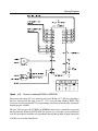
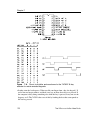
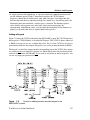
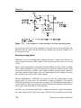
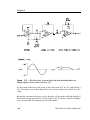
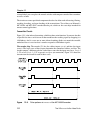
the newly latched data. The falling edge of RD brings INTR low again as the CPU reads the
data.
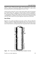
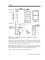
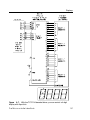
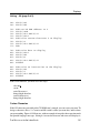
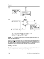
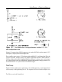
Output Control. For output ports in Mode 1, there is a complementary set of signals:
OBF (output buffer full output) goes low to indicate that the CPU has written data to U12.
OBF can signal a peripheral device (a display, for example) that it’s time to read data that the
8255 is holding for it.
ACK (acknowledge input) strobes low to tell the 8255 that the peripheral device has read the
data. ACK’s falling edge brings OBF high.
INTE (interrupt enable) is set to enable INTR. Its function is similar to its function for Mode
1’s inputs, except that Group A uses bit 6 of Port C, and Group B uses bit 2 of Port C.
INTR (interrupt request output) goes high to signal that a peripheral has accepted the data
written to U12. The falling edge of WR brings INTR low, and INTR goes high again when
ACK and OBF are both high and INTE is set, to signal that the peripheral has read and
acknowledged the data.
For both inputs and outputs, connecting INTR is optional.
Mode 1 leaves two bits of Port C unused. If Port A is input, the unused bits are 6 and 7. If
Port A is output, the bits are 4 and 5. You can use these as general-purpose inputs or outputs.
Bit 3 of the mode-select control word selects an input or output function for both bits.
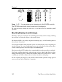
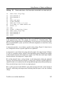
Mode 2 (Strobed Bidirectional Bus I/O) is similar to Mode 1, except that data can flow both
ways. Mode 2 can use all of the control signals used by Mode 1’s input and output modes,
and is available only for Port A. With Port A in Mode 2, Port B can be Mode 0 or 1, input
or output. The remaining three bits of Port C (0-2) can also be input or output, selected with
the control word.
108
The Microcontroller Idea Book