1
Displays
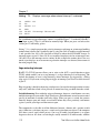
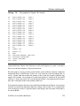
Each character in the CG ROM and CG RAM has an 8-bit address, or character code.
Conveniently, the codes for the upper and lower-case Roman alphabet and common
punctuation are same as the ASCII codes for those characters (21h through 7Dh). For
example, the pattern for A is stored at address 41h, B is stored at at 42h, and so on.
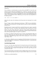
An 8-bit instruction register (IR) stores instruction codes and addresses, and an 8-bit data
register (DR) stores character codes. When you read or write to the chip, you must select
the appropriate register.
The DD RAM stores up to eighty 8-bit character codes. Each character position on the
display corresponds to an address in the DD RAM, and the character codes stored in the DD
RAM determine what is displayed at each position.
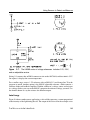
On power up, on a 2-line display, the leftmost position on the top line has an address of 0,
with the rest of the positions in the line addressed in sequence. The second line begins at
40h, even if the top line has fewer than 40h positions.
The instructions allow you to configure a module so that the DD RAM’s address increments
each time a character is written to the display. This way, the characters automatically appear
in sequence on the display without your having to specify an address each time.
Because the second line begins at 40h, however, the display will not wrap around automatically to this line. For example, on a 2-line, 16-position display, line 1 ends at 0Fh and line
2 begins at 40h. To move from the rightmost position of line 1 to the leftmost position of
line 2, you have to change the address counter to 40h. In addition, some displays with a
single physical line of characters have two logical lines. In a 16-character display of this
type, the first 8 characters are addressed from 0 to 7, and the second 8 are addressed from
40h to 47h. With this type of display, you must set the address counter to 40h before you
write to the second half of the line.
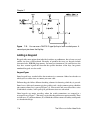
On a small display where all 80 bytes of DD RAM aren’t needed, you can use the spare DD
RAM as general-purpose RAM.
Reading and Writing
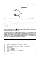
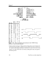
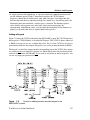
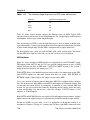
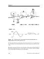
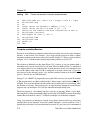
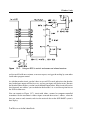
Writing to the LCD module involves the following steps:
Bring RS high to write data, or low to write an instruction.
Bring R/W low.
Bring D0-D7 to their desired states.
Wait at least 140 nanoseconds.
Bring E high for at least 450 nanoseconds.
Bring E low.
The Microcontroller Idea Book
143