1
Chapter 4
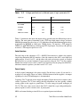
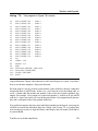
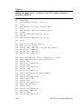
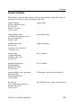
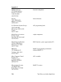
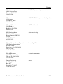
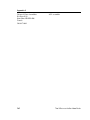
Table
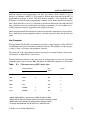
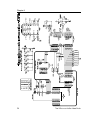
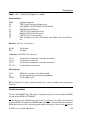
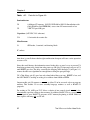
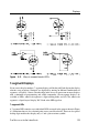
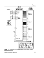
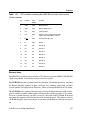
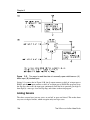
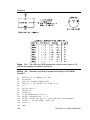
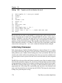
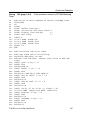
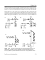
4-2. Parts list for Figure 4-5.
Semiconductors
D2,D3
Q1,Q2
U10
1N270 or similar germanium diode
PN2907 or similar PNP general-purpose transistor
75453 dual peripheral OR driver
Resistors (1/4-watt, 5% tolerance)
R11,R14
R12,R13
R15,R16
4,700-ohm
10,000-ohm
10,000-ohm
Capacitors(16WVDC, 20% tolerance)
C15
0.1-microfarad ceramic disc
Miscellaneous
J5-J6
SIP header, 3-terminal, and shorting block
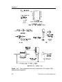
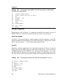
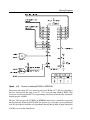
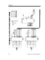
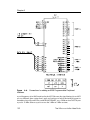
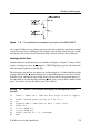
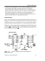
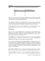
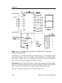
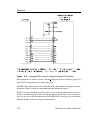
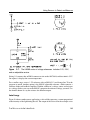
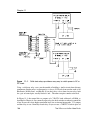
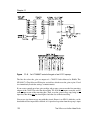
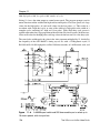
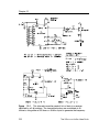
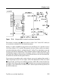
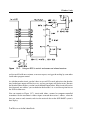
When BASIC-52 executes a programming command, PGM EN goes low, pin 3 of U10 goes
low, and Q1 switches on. This brings VPP to 12.5 volts. Diode D2 prevents current from
flowing into the 5V supply. When programming is finished, PGM EN goes high again, and
VPP returns to +4.7V.
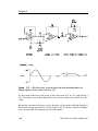
Resistor R10 limits U10A’s output current, and R11 ensures that pin 3 of U10 pulls up to
12.5V. Capacitor C14 provides power-supply decoupling.
If you happen to have an older 21V EPROM, the circuit should also work with a +21V
supply in place of +12.5V.
FPROG Circuits
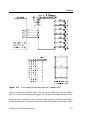
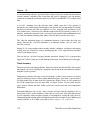
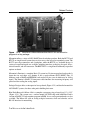
If you want to use the FPROG commands for faster EPROM programming, additional
circuits are required. These are identical to the circuits that switch VPP, except that they
instead switch VCC to +6V during programming.
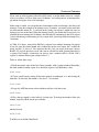
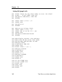
With the FPROG circuits shown in Figure 4-5, during normal (non-programming) operation,
VCC is actually slightly less than +5V, due to D3’s voltage drop. This should cause no
60
The Microcontroller Idea Book